EP2942260A2 - Behälter - Google Patents
Behälter Download PDFInfo
- Publication number
- EP2942260A2 EP2942260A2 EP15166736.7A EP15166736A EP2942260A2 EP 2942260 A2 EP2942260 A2 EP 2942260A2 EP 15166736 A EP15166736 A EP 15166736A EP 2942260 A2 EP2942260 A2 EP 2942260A2
- Authority
- EP
- European Patent Office
- Prior art keywords
- panel element
- container
- side frame
- frame section
- door
- Prior art date
- Legal status (The legal status is an assumption and is not a legal conclusion. Google has not performed a legal analysis and makes no representation as to the accuracy of the status listed.)
- Withdrawn
Links
- 235000004443 Ricinus communis Nutrition 0.000 description 3
- 230000032258 transport Effects 0.000 description 3
- 240000000528 Ricinus communis Species 0.000 description 1
- 230000008878 coupling Effects 0.000 description 1
- 238000010168 coupling process Methods 0.000 description 1
- 238000005859 coupling reaction Methods 0.000 description 1
- 238000006073 displacement reaction Methods 0.000 description 1
- 230000007246 mechanism Effects 0.000 description 1
- 239000002184 metal Substances 0.000 description 1
- 230000002093 peripheral effect Effects 0.000 description 1
- 238000009877 rendering Methods 0.000 description 1
- 239000007787 solid Substances 0.000 description 1
Images





Classifications
-
- B—PERFORMING OPERATIONS; TRANSPORTING
- B65—CONVEYING; PACKING; STORING; HANDLING THIN OR FILAMENTARY MATERIAL
- B65D—CONTAINERS FOR STORAGE OR TRANSPORT OF ARTICLES OR MATERIALS, e.g. BAGS, BARRELS, BOTTLES, BOXES, CANS, CARTONS, CRATES, DRUMS, JARS, TANKS, HOPPERS, FORWARDING CONTAINERS; ACCESSORIES, CLOSURES, OR FITTINGS THEREFOR; PACKAGING ELEMENTS; PACKAGES
- B65D88/00—Large containers
- B65D88/52—Large containers collapsible, i.e. with walls hinged together or detachably connected
- B65D88/522—Large containers collapsible, i.e. with walls hinged together or detachably connected all side walls hingedly connected to each other or to another component of the container
- B65D88/524—Large containers collapsible, i.e. with walls hinged together or detachably connected all side walls hingedly connected to each other or to another component of the container and one or more side walls being foldable along an additional median line
-
- B—PERFORMING OPERATIONS; TRANSPORTING
- B62—LAND VEHICLES FOR TRAVELLING OTHERWISE THAN ON RAILS
- B62B—HAND-PROPELLED VEHICLES, e.g. HAND CARTS OR PERAMBULATORS; SLEDGES
- B62B3/00—Hand carts having more than one axis carrying transport wheels; Steering devices therefor; Equipment therefor
- B62B3/002—Hand carts having more than one axis carrying transport wheels; Steering devices therefor; Equipment therefor characterised by a rectangular shape, involving sidewalls or racks
- B62B3/004—Details of doors or cover lids
-
- B—PERFORMING OPERATIONS; TRANSPORTING
- B65—CONVEYING; PACKING; STORING; HANDLING THIN OR FILAMENTARY MATERIAL
- B65D—CONTAINERS FOR STORAGE OR TRANSPORT OF ARTICLES OR MATERIALS, e.g. BAGS, BARRELS, BOTTLES, BOXES, CANS, CARTONS, CRATES, DRUMS, JARS, TANKS, HOPPERS, FORWARDING CONTAINERS; ACCESSORIES, CLOSURES, OR FITTINGS THEREFOR; PACKAGING ELEMENTS; PACKAGES
- B65D19/00—Pallets or like platforms, with or without side walls, for supporting loads to be lifted or lowered
- B65D19/02—Rigid pallets with side walls, e.g. box pallets
-
- B—PERFORMING OPERATIONS; TRANSPORTING
- B65—CONVEYING; PACKING; STORING; HANDLING THIN OR FILAMENTARY MATERIAL
- B65D—CONTAINERS FOR STORAGE OR TRANSPORT OF ARTICLES OR MATERIALS, e.g. BAGS, BARRELS, BOTTLES, BOXES, CANS, CARTONS, CRATES, DRUMS, JARS, TANKS, HOPPERS, FORWARDING CONTAINERS; ACCESSORIES, CLOSURES, OR FITTINGS THEREFOR; PACKAGING ELEMENTS; PACKAGES
- B65D25/00—Details of other kinds or types of rigid or semi-rigid containers
- B65D25/005—Side walls formed with an aperture or a movable portion arranged to allow removal or insertion of contents
-
- B—PERFORMING OPERATIONS; TRANSPORTING
- B65—CONVEYING; PACKING; STORING; HANDLING THIN OR FILAMENTARY MATERIAL
- B65D—CONTAINERS FOR STORAGE OR TRANSPORT OF ARTICLES OR MATERIALS, e.g. BAGS, BARRELS, BOTTLES, BOXES, CANS, CARTONS, CRATES, DRUMS, JARS, TANKS, HOPPERS, FORWARDING CONTAINERS; ACCESSORIES, CLOSURES, OR FITTINGS THEREFOR; PACKAGING ELEMENTS; PACKAGES
- B65D7/00—Containers having bodies formed by interconnecting or uniting two or more rigid, or substantially rigid, components made wholly or mainly of metal
- B65D7/12—Containers having bodies formed by interconnecting or uniting two or more rigid, or substantially rigid, components made wholly or mainly of metal characterised by wall construction or by connections between walls
-
- B—PERFORMING OPERATIONS; TRANSPORTING
- B62—LAND VEHICLES FOR TRAVELLING OTHERWISE THAN ON RAILS
- B62B—HAND-PROPELLED VEHICLES, e.g. HAND CARTS OR PERAMBULATORS; SLEDGES
- B62B2202/00—Indexing codes relating to type or characteristics of transported articles
- B62B2202/64—Documents, files or paper sheets
-
- B—PERFORMING OPERATIONS; TRANSPORTING
- B65—CONVEYING; PACKING; STORING; HANDLING THIN OR FILAMENTARY MATERIAL
- B65D—CONTAINERS FOR STORAGE OR TRANSPORT OF ARTICLES OR MATERIALS, e.g. BAGS, BARRELS, BOTTLES, BOXES, CANS, CARTONS, CRATES, DRUMS, JARS, TANKS, HOPPERS, FORWARDING CONTAINERS; ACCESSORIES, CLOSURES, OR FITTINGS THEREFOR; PACKAGING ELEMENTS; PACKAGES
- B65D2313/00—Connecting or fastening means
- B65D2313/04—Connecting or fastening means of magnetic type
Definitions
- the present invention relates to logistics equipment.
- the invention relates to containers for transporting divided goods, such as letters and small boxes sent by mail. More specifically, the invention relates to a container according to the preamble portion of claim 1.
- Conventional containers include three fixed wall sections and a door, which covers the fourth lateral side of the container. Both the fixed wall sections and the door feature a peripheral frame surrounding a mesh tight enough to safely keep all contents within the container.
- a problem associated with conventional roll containers is that when the door is opened, the contents of the container tend to fall out in an uncontrolled manner.
- the problem is most prominent in mail transport, wherein the letters are stacked on top of each other such that they can easily slide off the container thus creating a large spill.
- roll containers have been developed with two independent doors, which are arranged in a superposed configuration. Both doors are vertically hinged to the front edge of the same side frame section such that the hinges enable also vertical displacement for locking the door to the opposing frame section.
- the top door may therefore be opened independently of the lower door.
- the aim of the present invention is achieved with aid of a novel container including a side frame section and a hinge, which pivots a door in respect to the side frame section about a vertical axis for turning the door between a closed and open configuration.
- the door features a first and second panel element, which both include a rectangular frame including a horizontal beam.
- the first panel element is attached to the side frame section through the hinge.
- a pivoting member is arranged to connect the horizontal beams of the first and second panel element and configured to provide a horizontal axis of revolution between the panel elements.
- the container according to the present invention is characterized by the characterizing portion of claim 1.
- the door is made of panel elements, which are hinged together by using their hollow beams, the door may be opened sequentially about the horizontal axis and there is no gap between the panel elements.
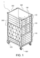
- a container 1 includes a fixed first and second side frame section 200, 400 and a rear frame section 300 connecting the two.
- Each frame section 200, 300, 400 includes a rectangular frame and a mesh for covering the side.
- the door 100 has three portions, namely a bottom, center and top portions, which are herein referred to as the first, second and third panel elements 110, 120, 130, respectively.
- a panel element is meant to refer to an enclosing element of the container, which extends over at least a portion of a side of the container such to prevent items inside the container from exiting the container.
- the panel need not be solid, wherein a mere frame with a mesh may fulfill the above requirements.
- the panel elements include a rectangular frame of interconnected beams and a mesh delimited by said frame.
- the panel elements 110, 120, 130 are hinged together horizontally, which is described with greater detail hereafter.
- the door 100 is hinged vertically to the first side frame section 200 and constructed to lock on to the third side frame section 300 opposing the first side frame section 200.
- Fig. 1 also shows that the container 1 is preferably equipped with fixed and swivel castors 510, 520, which known in the field per se, thus rendering the container a roll container.
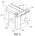
- the top portion of the door 100 i.e. the third panel element 130
- the extension 131a extending from the top horizontal beam 130 of the third panel element 130 is shaped to be vertically inserted to a receptive bracket 204 provided to the front vertical beam 202 of the first side frame section 200.
- a similar attachment is provided at the other end of the third panel element 130.
- the vertical beam 132 of the third panel element 130 makes contact or at least closely flanks the vertical beam 202 of the adjacent side frame section 200.
- the mesh 133, 203 on both the third panel element 130 and the side frame section 200 is dimensioned to prevent any content, particularly letters, of the container from falling out.
- a releaser 134 which includes a slanted slide (not shown) inside the top horizontal beam 131.
- the slide is biased to the beam 131 by means of a spring such to bias the slide towards the locked position shown in Fig. 2 .
- a protrusion extending through an opening in the top horizontal beam 131 and to a receptive opening (not shown) in the bracket 204.
- the second and third panel element 120, 130 are horizontally hinged together through a pivoting member 140 ( Fig. 3 ).
- the pivoting member 140 includes to elongated pieces that run in the hollow bottom horizontal beam 135 of the third panel element 130 and in the adjacent and parallel hollow top horizontal beam 121 of the second panel element 120. The elongated pieces are joined together outside the hollow beams 121, 135. The elongated pieces of the pivoting member 140 are spaced apart by a distance such that the third panel element 130 may be elevated from the second panel element 120 by a height corresponding to said distance without excreting any lifting force to the second panel element 120.
- the pivoting member 140 is attached to the second and third panel element 120, 130 such that the horizontal beams 121, 135 may be pivoted in respect to each other and in respect to the pivoting member 140, whereby the panel elements 120, 130 may be pivoted in respect to each other about a horizontal rotation axis.
- Fig. 3 also shows how the second and third panel elements 120, 130 are suspended to the first side frame section 200.
- the vertical beam 202 of the side frame section 200 has brackets 204 arranged at suitable heights to receive the anchors 126, 136 of the second and third panel element 120, 130, respectively.
- the anchors 126, 135 have a vertical extension, which has been dimensioned with the pivoting member 140 such that the clearance between the elongated pieces of the pivoting member 140 is no shorter than the vertical extension of the anchor 126, 136.
- the vertical extension of the anchor 136 escapes the bracket 204, whereby the pivoting member 140 is similarly elevated by the bottom horizontal beam 135 of the third panel element 130.
- the second panel element 120 Due to the vertical clearance between the elongated pieces of the pivoting element 140 and to the vertical extent of the inner cavity of the top horizontal beam 121 of the second panel element 120, the second panel element 120 is not elevated. Thus, the third panel element 130 may be freely elevated and rotated in respect to the second panel element 120.
- the front vertical beam 202 of the first side frame section 200 has been provided with a limiter 205 for limiting the vertical movement of the third panel element 130.
- the limiter 205 is a projection from the front vertical beam 202 of the first side frame section 200 arranged at a distance from the bracket 204. The distance is dimensioned to be no greater than the vertical extent of the inner cavity of the top horizontal beam 121 of the second panel element 120. The limiter 205 therefore prevents the third panel element 130 to be lifted high enough that the pivoting member 140 would begin to lift the second panel element 120.
- the third panel element 130 when the third panel element 130 is opened, it is firstly released from the side frame panels 200, 300 by moving the releaser, where after the panel element 130 is elevated to release the anchor 136 and the extension 131a of the top horizontal beam 131 from the brackets 204.
- the panel element 130 is secondly rotated about the horizontal rotation axis created by the pivoting member 140 in respect to the second panel element 120.
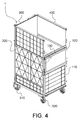
- Fig. 4 shows the container with the third panel element 130 opened.
- Fig. 5 shows, how the third panel element 130 is suspended by from the second panel element 120 by the pivoting member 140 there between. While not shown in the Figs., it is to be pointed out that the third panel element 130 is releasably locked to flank the second panel element 120 by virtue of the magnet 137 disposed to the top horizontal beam of the third panel element 130.
- the second panel element 120 features similar locking and pivoting mechanisms in respect to the side frame sections 200, 300 and the first panel element 110.
- the second panel element 120 does not, however, include an extended top horizontal beam.
- the second panel element 120 may therefore be similarly opened by folding it down about the horizontal rotation axis created by the pivoting member connecting the hollow top horizontal beams of the second and first panel elements 120, 110.
- the third panel element 130 is attached to the second panel element 120 by means of the magnet 137, the third panel element 130 is also pivoted in respect to the first panel element 110 carried by the second panel element 120.
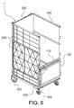
- Fig. 6 shows the roll container opened two thirds such that both the third and second panel elements are folded open.
- Fig. 7 shows the relationship between the panel elements 110, 120, 130 in a folded configuration.
- the pivoting member 140 connects the top horizontal beams 111, 125 similarly as described above between the second and third panel elements 120, 130.
- Fig. 7 further illustrates how the door 100, namely the first panel element 110 is hinged to the first side frame section 200.
- the rear surface of the front vertical beam 202 of the first side frame section 200 has been provided with frame sleeves 601 with a main sleeve 603 hinged there between via a pin 602.
- the main sleeve 603 is attached to a door sleeve 605 via a leaf 604.
- the first panel element 110 also has a second door sleeve 605 connected to the first door sleeve 605 with a pin (shown at 606 in Fig. 11 ).
- the first panel element 110 may therefore be pivoted about a vertical axis along the door sleeves 605 and a second vertical axis along the frame sleeves 601, with the two vertical axes being horizontally separated by the leaf 604.
- Figs. 3 , 5 and 7 illustrate an embodiment for constructing the pivoting member 140 from two parallel pins joined together at one end.
- Figs. 9 to 11 show an alternative embodiment to the example shown in Figs. 3 , 5 and 7 , respectively.
- Fig. 9 presents the pivoting member 140 in an upright orientation between the second and third panel element 120, 130.
- the pivoting member 140 includes two pins that run parallel and that are joined together at one end. Instead of being shaped to merge at the end facing the hinge of the door 100, the pivoting member 140 includes a separate bond piece.
- the bond piece is in the illustrated example equipped with a horizontal extension 141 for making contact with a limiter 205 provided to the front vertical beam 202 of the first side frame section 200 similarly to the limiter arrangement shown in connection with Figs. 3 , 5 and 7 .
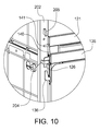
- Fig. 10 shows the pivoting member 140 according to the second embodiment in an angled orientation between the second and third panel element 120, 130, when the third panel element 130 is opened and flanking the second panel element 120.
- Fig. 11 shows the pivoting member 140 according to the second embodiment in an angled orientation between the first and second panel element 110, 120, when the second panel element 120 is opened and flanking the first panel element 110.
- the door 100 may be completely opened by lifting the first panel element 110 to release it from the brackets 204 and pivoting the stack of folded panel elements 110, 120, 130 about the pins 602 to turn the door 100 to flank the first frame section 200, as shown in Fig. 8 .
- the anchors used to suspend the door 100 - namely the first panel element 110 thereof - to the brackets 204 of the second side frame section 300 may be used to suspend the door 100 to the first side frame section 200, which may be equipped with receptive brackets (not shown).
- the rear surface of a horizontal beam 121, 125 of the second panel element 120 which is the outermost panel element in the folded configuration, may be provided with a magnetic coupling (not shown) for releasably attaching the door 100 to the first side frame section 200.
- the door 100 is closed in a reversed order. First, the door 100 is turned about the pins 602 back to connect the first and second side frame section 200, 300. The door is simultaneously lifted, where after the free end of the first panel element 110 is aligned with the brackets 204 provided to the vertical front beams of the first and second side frame section 200, 300 ( Fig. 6 ). The door 100 is suspended to the side frame sections 200, 300 by dropping the anchors into the receptive brackets.
- the second panel element 120 is pivoted in respect to the first panel element 110 about the pivoting member 140 from the flanking parallel position into the superposed aligned position, where after the second panel element 120 is dropped for inserting the anchors 126 into the receptive brackets 204 for locking the second panel element 120 to the side frame sections 200, 300 ( Fig. 4 ).
- the bottom horizontal beam 125 of the second panel element 120 rests against the top horizontal beam 111 of first panel element 110.
- the third panel element 130 is released from the flanking position by exceeding the holding force between the magnet 137 and the metal structure of the second panel element 120.
- the first panel element 110 Being detached from the second panel element 120, the first panel element 110 is pivoted in respect to the second panel element 120 about the pivoting member 140 from the flanking parallel position into the superposed aligned position, where after the third panel element 130 is dropped for inserting the anchors 126 into the receptive brackets 204 for locking the third panel element 130 to the side frame sections 200, 300 ( Fig. 1 ). Simultaneously the extension 131a of the top horizontal beam 131 of the third panel element 130 is inserted into the receptive bracket 204. In such a configuration the bottom horizontal beam 135 of the third panel element 130 rests against the top horizontal beam 121 of second panel element 120. TABLE 1: LIST OF REFERENCE NUMBERS.
Landscapes
- Engineering & Computer Science (AREA)
- Mechanical Engineering (AREA)
- Chemical & Material Sciences (AREA)
- Combustion & Propulsion (AREA)
- Transportation (AREA)
- Closures For Containers (AREA)
- Hinges (AREA)
- Pallets (AREA)
- Rigid Containers With Two Or More Constituent Elements (AREA)
Applications Claiming Priority (1)
| Application Number | Priority Date | Filing Date | Title |
|---|---|---|---|
| GB1408162.4A GB2525909A (en) | 2014-05-08 | 2014-05-08 | Container |
Publications (2)
| Publication Number | Publication Date |
|---|---|
| EP2942260A2 true EP2942260A2 (de) | 2015-11-11 |
| EP2942260A3 EP2942260A3 (de) | 2016-01-06 |
Family
ID=51032442
Family Applications (2)
| Application Number | Title | Priority Date | Filing Date |
|---|---|---|---|
| EP15166736.7A Withdrawn EP2942260A3 (de) | 2014-05-08 | 2015-05-07 | Behälter |
| EP15166876.1A Withdrawn EP2942262A3 (de) | 2014-05-08 | 2015-05-08 | Behälter |
Family Applications After (1)
| Application Number | Title | Priority Date | Filing Date |
|---|---|---|---|
| EP15166876.1A Withdrawn EP2942262A3 (de) | 2014-05-08 | 2015-05-08 | Behälter |
Country Status (2)
| Country | Link |
|---|---|
| EP (2) | EP2942260A3 (de) |
| GB (1) | GB2525909A (de) |
Cited By (2)
| Publication number | Priority date | Publication date | Assignee | Title |
|---|---|---|---|---|
| EP3461718A1 (de) * | 2017-09-22 | 2019-04-03 | K. Hartwall Oy AB | Behälter |
| CN110884875A (zh) * | 2019-10-24 | 2020-03-17 | 安徽神力运输机械有限公司 | 一种多层出料口带式输送机末端用的防物体掉落运输架 |
Families Citing this family (1)
| Publication number | Priority date | Publication date | Assignee | Title |
|---|---|---|---|---|
| JP7297029B2 (ja) * | 2021-07-02 | 2023-06-23 | グリーン プラス カンパニー,リミテッド | 折り畳み式軽量ロールコンテナー |
Family Cites Families (8)
| Publication number | Priority date | Publication date | Assignee | Title |
|---|---|---|---|---|
| FR2128154B2 (de) * | 1971-03-08 | 1974-02-15 | Semico | |
| DE2339197A1 (de) * | 1973-08-02 | 1975-02-13 | Werner Cordes | Kaefigfoermiger, faltbarer transportwagen |
| US4222579A (en) * | 1976-08-31 | 1980-09-16 | Elopak A/S | Nestable trolley with volume regulation |
| DE3323564A1 (de) * | 1983-06-30 | 1985-01-10 | Freimuth Gmbh, 5948 Schmallenberg | Mehrwege-kunststoffpalette mit aufsetzrahmen |
| FR2627142A1 (fr) * | 1988-02-12 | 1989-08-18 | Siekierski Bernard | Chariot transporteur et convoyeur plus particulierement pour des petits colis |
| CH678842A5 (en) * | 1989-05-18 | 1991-11-15 | Stoecklin Ag Walter | Pallet-extension cage - has end walls permanently hinging on rear wall with positioning stops at bottom |
| FR2743706B1 (fr) * | 1996-01-18 | 1998-04-10 | Pepinieres Desmartis | Container pour le transport de vegetaux |
| GB2506396B (en) * | 2012-09-28 | 2015-03-04 | Hartwall K Oy Ab | Roll container |
-
2014
- 2014-05-08 GB GB1408162.4A patent/GB2525909A/en not_active Withdrawn
-
2015
- 2015-05-07 EP EP15166736.7A patent/EP2942260A3/de not_active Withdrawn
- 2015-05-08 EP EP15166876.1A patent/EP2942262A3/de not_active Withdrawn
Non-Patent Citations (1)
| Title |
|---|
| None * |
Cited By (3)
| Publication number | Priority date | Publication date | Assignee | Title |
|---|---|---|---|---|
| EP3461718A1 (de) * | 2017-09-22 | 2019-04-03 | K. Hartwall Oy AB | Behälter |
| CN110884875A (zh) * | 2019-10-24 | 2020-03-17 | 安徽神力运输机械有限公司 | 一种多层出料口带式输送机末端用的防物体掉落运输架 |
| CN110884875B (zh) * | 2019-10-24 | 2021-07-20 | 安徽神力运输机械有限公司 | 一种多层出料口带式输送机末端用的防物体掉落运输架 |
Also Published As
| Publication number | Publication date |
|---|---|
| GB201408162D0 (en) | 2014-06-25 |
| EP2942262A2 (de) | 2015-11-11 |
| EP2942260A3 (de) | 2016-01-06 |
| EP2942262A3 (de) | 2016-01-06 |
| GB2525909A (en) | 2015-11-11 |
Similar Documents
| Publication | Publication Date | Title |
|---|---|---|
| US9050986B2 (en) | Roll container | |
| US6305566B1 (en) | Container for fragile articles | |
| US10251503B1 (en) | Secure delivery/drop box for parcels and products | |
| US5660291A (en) | Collapsible cage | |
| US8590714B1 (en) | Cash box holding apparatus | |
| US11503936B2 (en) | Mailbox for storing packages | |
| US10646062B1 (en) | Security mailbox | |
| US8286562B2 (en) | Transportable load carrying platform | |
| EP2942260A2 (de) | Behälter | |
| CN113460518A (zh) | 折叠式集装箱用铰链装置及折叠式集装箱 | |
| US20040140305A1 (en) | Storage box | |
| US10647239B2 (en) | Door prop assembly | |
| CN202529249U (zh) | 由塑性材料制成的运输容器、特别是运输箱 | |
| US20220297883A1 (en) | Stackable container having hinged walls | |
| US10351295B2 (en) | Display container | |
| CN115676079B (zh) | 可折叠容器 | |
| CN105078179B (zh) | 具有可拆装邮箱的邮箱系统 | |
| US20110127259A1 (en) | Freight container with doors | |
| JP4805405B1 (ja) | 折りたたみ貨物架台 | |
| FI129687B (en) | A gripper and an attachment interface for an automated storage system as well as an automated storage system comprising the same | |
| GB2368336A (en) | A freight container | |
| JPH09323786A (ja) | パネル式コンテナ | |
| CN218623876U (zh) | 可用作安全围栏的翻转门 | |
| US20240417162A1 (en) | Container with rampwall | |
| GB2292306A (en) | Support for pivoting shelves |
Legal Events
| Date | Code | Title | Description |
|---|---|---|---|
| PUAI | Public reference made under article 153(3) epc to a published international application that has entered the european phase |
Free format text: ORIGINAL CODE: 0009012 |
|
| AK | Designated contracting states |
Kind code of ref document: A2 Designated state(s): AL AT BE BG CH CY CZ DE DK EE ES FI FR GB GR HR HU IE IS IT LI LT LU LV MC MK MT NL NO PL PT RO RS SE SI SK SM TR |
|
| AX | Request for extension of the european patent |
Extension state: BA ME |
|
| PUAL | Search report despatched |
Free format text: ORIGINAL CODE: 0009013 |
|
| AK | Designated contracting states |
Kind code of ref document: A3 Designated state(s): AL AT BE BG CH CY CZ DE DK EE ES FI FR GB GR HR HU IE IS IT LI LT LU LV MC MK MT NL NO PL PT RO RS SE SI SK SM TR |
|
| AX | Request for extension of the european patent |
Extension state: BA ME |
|
| RIC1 | Information provided on ipc code assigned before grant |
Ipc: B62B 3/00 20060101AFI20151130BHEP Ipc: B65D 25/00 20060101ALI20151130BHEP |
|
| 17P | Request for examination filed |
Effective date: 20160630 |
|
| RBV | Designated contracting states (corrected) |
Designated state(s): AL AT BE BG CH CY CZ DE DK EE ES FI FR GB GR HR HU IE IS IT LI LT LU LV MC MK MT NL NO PL PT RO RS SE SI SK SM TR |
|
| 17Q | First examination report despatched |
Effective date: 20170519 |
|
| STAA | Information on the status of an ep patent application or granted ep patent |
Free format text: STATUS: THE APPLICATION IS DEEMED TO BE WITHDRAWN |
|
| 18D | Application deemed to be withdrawn |
Effective date: 20180126 |