EP2942262A2 - Behälter - Google Patents
Behälter Download PDFInfo
- Publication number
- EP2942262A2 EP2942262A2 EP15166876.1A EP15166876A EP2942262A2 EP 2942262 A2 EP2942262 A2 EP 2942262A2 EP 15166876 A EP15166876 A EP 15166876A EP 2942262 A2 EP2942262 A2 EP 2942262A2
- Authority
- EP
- European Patent Office
- Prior art keywords
- panel
- door
- container
- side frame
- frame section
- Prior art date
- Legal status (The legal status is an assumption and is not a legal conclusion. Google has not performed a legal analysis and makes no representation as to the accuracy of the status listed.)
- Withdrawn
Links
- 230000007246 mechanism Effects 0.000 claims description 26
- 210000000078 claw Anatomy 0.000 claims description 3
- 239000000463 material Substances 0.000 description 6
- 230000032258 transport Effects 0.000 description 4
- 230000008901 benefit Effects 0.000 description 3
- 238000010276 construction Methods 0.000 description 3
- 239000002184 metal Substances 0.000 description 2
- 238000000034 method Methods 0.000 description 2
- 230000004048 modification Effects 0.000 description 2
- 238000012986 modification Methods 0.000 description 2
- 230000000717 retained effect Effects 0.000 description 2
- 239000002131 composite material Substances 0.000 description 1
- 230000001419 dependent effect Effects 0.000 description 1
- 238000006073 displacement reaction Methods 0.000 description 1
- 239000013013 elastic material Substances 0.000 description 1
- 230000002093 peripheral effect Effects 0.000 description 1
- 239000011120 plywood Substances 0.000 description 1
- 239000012779 reinforcing material Substances 0.000 description 1
- 239000000725 suspension Substances 0.000 description 1
Images



Classifications
-
- B—PERFORMING OPERATIONS; TRANSPORTING
- B62—LAND VEHICLES FOR TRAVELLING OTHERWISE THAN ON RAILS
- B62B—HAND-PROPELLED VEHICLES, e.g. HAND CARTS OR PERAMBULATORS; SLEDGES
- B62B3/00—Hand carts having more than one axis carrying transport wheels; Steering devices therefor; Equipment therefor
- B62B3/002—Hand carts having more than one axis carrying transport wheels; Steering devices therefor; Equipment therefor characterised by a rectangular shape, involving sidewalls or racks
- B62B3/004—Details of doors or cover lids
-
- B—PERFORMING OPERATIONS; TRANSPORTING
- B65—CONVEYING; PACKING; STORING; HANDLING THIN OR FILAMENTARY MATERIAL
- B65D—CONTAINERS FOR STORAGE OR TRANSPORT OF ARTICLES OR MATERIALS, e.g. BAGS, BARRELS, BOTTLES, BOXES, CANS, CARTONS, CRATES, DRUMS, JARS, TANKS, HOPPERS, FORWARDING CONTAINERS; ACCESSORIES, CLOSURES, OR FITTINGS THEREFOR; PACKAGING ELEMENTS; PACKAGES
- B65D25/00—Details of other kinds or types of rigid or semi-rigid containers
- B65D25/005—Side walls formed with an aperture or a movable portion arranged to allow removal or insertion of contents
-
- B—PERFORMING OPERATIONS; TRANSPORTING
- B65—CONVEYING; PACKING; STORING; HANDLING THIN OR FILAMENTARY MATERIAL
- B65D—CONTAINERS FOR STORAGE OR TRANSPORT OF ARTICLES OR MATERIALS, e.g. BAGS, BARRELS, BOTTLES, BOXES, CANS, CARTONS, CRATES, DRUMS, JARS, TANKS, HOPPERS, FORWARDING CONTAINERS; ACCESSORIES, CLOSURES, OR FITTINGS THEREFOR; PACKAGING ELEMENTS; PACKAGES
- B65D7/00—Containers having bodies formed by interconnecting or uniting two or more rigid, or substantially rigid, components made wholly or mainly of metal
- B65D7/12—Containers having bodies formed by interconnecting or uniting two or more rigid, or substantially rigid, components made wholly or mainly of metal characterised by wall construction or by connections between walls
-
- B—PERFORMING OPERATIONS; TRANSPORTING
- B62—LAND VEHICLES FOR TRAVELLING OTHERWISE THAN ON RAILS
- B62B—HAND-PROPELLED VEHICLES, e.g. HAND CARTS OR PERAMBULATORS; SLEDGES
- B62B2202/00—Indexing codes relating to type or characteristics of transported articles
- B62B2202/64—Documents, files or paper sheets
-
- B—PERFORMING OPERATIONS; TRANSPORTING
- B65—CONVEYING; PACKING; STORING; HANDLING THIN OR FILAMENTARY MATERIAL
- B65D—CONTAINERS FOR STORAGE OR TRANSPORT OF ARTICLES OR MATERIALS, e.g. BAGS, BARRELS, BOTTLES, BOXES, CANS, CARTONS, CRATES, DRUMS, JARS, TANKS, HOPPERS, FORWARDING CONTAINERS; ACCESSORIES, CLOSURES, OR FITTINGS THEREFOR; PACKAGING ELEMENTS; PACKAGES
- B65D2313/00—Connecting or fastening means
- B65D2313/04—Connecting or fastening means of magnetic type
Definitions
- the present invention relates to logistics equipment.
- the invention relates to containers for transporting divided goods, such as letters and small boxes sent by mail. More specifically, the invention relates to a container according to the preamble portion of claim 1.
- Conventional containers include three fixed wall sections and a door, which covers the fourth lateral side of the container. Both the fixed wall sections and the door feature a peripheral frame surrounding a mesh tight enough to safely keep all contents within the container.
- a problem associated with conventional roll containers is that when the door is opened, the contents of the container tend to fall out in an uncontrolled manner.
- the problem is most prominent in mail transport, wherein the letters are stacked on top of each other such that they can easily slide off the container thus creating a large spill.
- roll containers have been developed with two independent doors, which are arranged in a superposed configuration. Both doors are vertically hinged to the front edge of the same side frame section such that the hinges enable also vertical displacement for locking the door to the opposing frame section.
- the top door may therefore be opened independently of the lower door.
- a novel container including a first side frame section, a door and a hinge, which is configured to pivot the door in respect to the side frame section about a vertical axis for turning the door between a closed state and an open state.
- the door includes a door frame, which is connected to the side frame section of the container through the hinge.
- the door has a first panel, which is fixed to the door frame, and a second panel, which is pivotably connected to the first panel and configured to be articulated about a horizontal rotation axis between a closed orientation and an open orientation.
- embodiments are based on the idea of providing a container door with a frame having a fixed bottom panel and one movable panel hinged to the top edge of the bottom panel.
- the door may include additional movable panels, each hinged to the top edge of the panel below.
- the panels of the door are fitted to the door frame, which is hinged to a side frame section of the container. Accordingly, small items are less likely to pour out of the roll container upon unloading as the door may be opened sequentially from top to bottom.
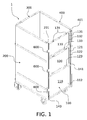
- a container 1 takes the form of a roll container. While the features of the container 1 are herein described in connection with a roll container, the novel door arrangement would be equally applicable to any container without any modification to the underside of the container.
- the container 1 includes four major components: a first side frame section 200, a second side frame section 400 on the opposite side of the container 1 to the first side frame sections 200, a back frame section 300 connecting the first and second side frame sections 200, 400 at the back of the container 1 and a door 100 provided to the front of the container 1 and connecting the first and second side frame sections 200, 400 in the closed state.
- the door 100 is connected to the first side frame section 200 via a hinge 600, which pivots the door 100 in respect to the side frame section 200 about a vertical axis for turning the door 100 between a closed state and an open state through intermediate positions there between. More specifically, the door 100 includes a door frame 140, which is connected to the side frame section 200 of the container 1 through the hinge 600.
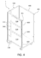
- the hinge 600 particularly connects the door frame 140 to the front profile 201 of the first side frame section 200 ( FIGURE 4 ).
- the door 100 In the closed state, the door 100 extends between the first and second side frame section 200, 400 ( FIGURES 1 to 3 ).
- the door frame 140 is then connected to the front profiles 201, 401 of the side frame sections 200, 400 so as to sufficiently seal the door 100 for preventing the items in the container from escaping through gaps between the door 100 and the surrounding side frame sections 200, 400.
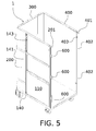
- the door 100 In the opened state, the door 100 is turned to extend parallel to the first side frame section 200, i.e. to flank the first side frame section 200 ( FIGURES 4 and 5 ).
- the door 100 has three panels 110, 120, 130.
- the first panel 110 is fixed to the door frame 140, which delimits the first panel 110 from both sides and from below.
- the first panel 110 includes a cover 112, which extends between the lateral and bottom portions of the door frame 140.
- the cover 112 may be a plywood, metal mesh, composite, plastic or similar panel for closing the bottom section of the door 100.
- the cover is preferably self-supporting.
- the first panel 110 also preferably includes a top frame portion for the purpose of acting as a hinge point for a superposed second panel 120.
- the top frame portion may be of reinforcing material, such as metal.
- FIGURE 1 illustrates a closed first panel 110 in the closed state of the door 100
- FIGURE 5 shows a closed first panel 110 in the opened state of the door 100.
- the door 100 also includes a second panel 120, which is pivotably connected to the first panel 110 ( FIGURE 1 ).
- the second panel 120 has a frame 121, which is dimensioned to fit between the lateral sections of the door frame 140.
- the frame 121 also surrounds a cover 122.
- the cover 122 of the second panel 120 may be similar to that of the first panel 110.
- the second panel 120 is articulated in respect to the first panel 100 about a horizontal rotation axis between a closed orientation and an open orientation. The articulation is established through a hinge 123 connecting the frame 121 of the second panel, namely the bottom section of the frame 121, to the first panel 110, preferably to the top frame portion thereof.
- FIGURE 1 shows the second panel 120 in a closed state, in which the second panel 120 extends upwardly from the first panel 110. In the closed state, the second panel 120 thus extends in the same plane as the first panel 110. Indeed, all panels of the roll container 1 are delimited by the door frame 140 in the closed orientation of the panels.
- the frame 121 of the second panel 120 also includes a panel release mechanism, which releasably engages with the door frame 140 for securing the second panel 120 to and releasing it from the closed orientation.
- the panel release mechanism is preferably arranged to inside the hollow top section of the frame 121 of the second panel.
- FIGURE 1 shows release latches 135 visible through openings provided to the top section of the frame 121. The operating principle and construction of the panel release mechanism is described hereafter in connection with the discussion of the third panel 130.
- the first and second panel 110, 120 may be provided with detachable and cooperating connectors, such as magnetic couplers, Velcro fasteners, or similar, for securing two hinged panels in respect to each other in the open position, in which mutually parallel panels maintain their respective position. More specifically, the front surface of the panels may include for example magnets, which are aligned when the second panel 120 is opened to flank the first panel 110. The releasable connection between the panels benefits the maneuverability of the door 100 in the different states.
- the container 1 shown in the FIGURES contains an additional and optional third panel 130.
- the third panel 130 is pivotably connected to the second panel 120.
- the pivoted connection is established with a hinge 133, which connects the bottom section of the frame 131 of the third panel 130 to the top section of the frame 121 of the second panel 120.
- the third panel 130 may be constructed similarly to the second panel 120. Accordingly, the third panel 130 may be pivoted in respect to the second panel 120 about a horizontal rotation axis between a closed orientation, in which the third panel 130 extends in the same plane as the second panel 120, and an open orientation, in which the third panel 130 is turned to flank the second panel 120.
- the hinge 133 allowing the third panel 130 to be rotated between the closed and open orientation preferably forces the third panel 130 to turn outward, i.e. away from the back frame section 300.
- the hinge 133 between the second and third panel 120, 130 is also preferably configured to have minimal offset between the panels 120, 130.
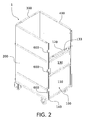
- FIGURE 1 shows a flat hinge as one exemplary configuration. The minimal offset brings the third panel 130 close to the second panel 120 in the open orientation ( FIGURE 2 ).
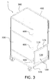
- the hinge 123 between the first and second panel 120 is configured to include more offset than the afore-mentioned hinge 133. The increased offset provides clearance to pivot the second and third panel 120, 130 together about the hinge 123 ( FIGURES 2 and 3 ). In the state of FIGURE 3 , the third panel is folded between the first panel and second panel 120, which is thus visible from the outside.
- the door 100 has two primary states (open and closed) both having three sub-states dictated by the orientation of the second and third panel 120, 130.
- FIGURE 2 shows the container 1 with the door 100 closed and only the third panel 130 opened, i.e. folded down.
- FIGURE 3 shows the container 1 with the door 100 closed and both movable panels 120, 130 opened, i.e. folded down.
- FIGURE 4 shows the container 1 with the door 100 opened and all panels 110, 120, 130 closed.
- FIGURE 5 shows the container 1 with the door 100 opened and both movable panels 120, 130 opened, i.e. folded down.
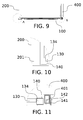
- FIGURES 9 to 11 show the operating principle of the panel release mechanism in greater detail. While the panel release mechanism is described in connection with the third panel 130, a similar mechanism is applicable to and preferably also used on the second panel 120.
- the release latch shown 135 in FIGURE 1 runs in the hollow top profile of the frame 131 of the third panel 130 and terminates to the affixer 134 shown in FIGURES 10 and 11 .
- the affixer 134 is a claw-like member, which may be moved along the profile of the frame 131 by moving the release latch 135 in the same direction.
- the door frame 140 includes an opening for releasably receiving and holding the affixer 134 of the third panel 130 for securing the panel to and releasing it from the closed orientation.
- FIGURES 10 and 11 show the third panel 130 in closed orientation, wherein the affixers 134 are held in the receptive opening on the door frame 140.
- the panel release mechanism preferably includes a biasing member, such as a spring with suitable retainers, for biasing the affixers 134 laterally such that the panel is released from the closed orientation by moving the release latches 135 enough to exceed the holding threshold of the biasing member to disengage the affixer 134 from the corresponding opening.
- a biasing member such as a spring with suitable retainers
- the door 100 also includes a door release mechanism 700 for locking the door 100 into and releasing from the closed state.
- the locking mechanism 700 is arranged to the front frame profile 401 of the second side frame section 400 such to be manipulated between a locking position and a releasing position for locking the door into the closed state and releasing it, respectively.
- the door frame 140 has a locking member 142 and the door release mechanism 700 has a counterpart member 701.
- the counterpart member 701 is set to engage with the locking member 142 of the door frame 140 in the locking position of the door release mechanism 700 and to release the locking member 142 in the releasing position of the door release mechanism 700.
- the counterpart member 701 is specifically a slide, which is set to run in and along the main extending direction of the front frame profile 401 of the second frame section 400.
- the counterpart member 701 takes the form of a slide.
- the slide 701 is visible through an opening 402 on the front profile 401 of the second side frame section 400.
- the slide 701 also has a corresponding opening 703, which aligns with the opening 402 of the front frame profile 401 in the releasing position and which is deviated from the opening 402 of the front frame profile 401 in the locking position of the slide 701.
- FIGURE 6 shows the slide 701 in the locking position.
- the opening 703 of the slide 701 is not aligned with the opening 402 of the profile 401.
- the edge of the opening 703 of slide 701 rests against the locking member 142 of the door 100.
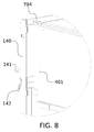
- the edge of the opening 703 of slide 701 is detached from the locking member 142, whereby the openings 703, 402 are aligned and the locking member 142 is free to be retracted through the aligned openings 703, 402 for opening the door 100 ( FIGURES 7 and 8 ).
- the locking member 142 is a protrusion that terminates to a claw, such as shown in FIGURE 6 .
- the door frame 140 includes a laterally extending locking plate 141, from which the locking member 142 extends towards the second side frame section 400 in the closed state of the door 100.
- the locking plate 141 provides a lateral offset for the locking member 142 from the profile of the door frame 140.
- the slide 701 is operated with a know 704, which is visible to the user and set to move the slide 701 inside the front frame profile 401 along its main extending direction.
- the knob is understood to be a gripping member suitable for manual grabbing.
- the knob 704 is connected to the slide 701 via a connecting rod 702.
- the connecting rod 702 which is preferably suspended in respect to the front frame profile 401 such to bias the slide 701 toward the locking position, i.e. downward.
- the suspension may be established by arranging a tension spring 706 around the connecting rod 702 such that the bottom end is retained by the edge of the slide 701 and the top end is retained by a spring limiter 705.
- the spring limiter 705 is fixed to the profile 401 and hollow to allow the connecting rod 702 to reciprocate through.
- the bottom end of the slide 701 is connected to another connecting rod 708, which terminates to a stopper (not shown) that limits the movement of the slide 701 along the profile 401, i.e. vertically.
- the door release mechanism 700 is therefore adapted to only allow the door 100 to open, when the operator pulls the knob 704 upward, which has the benefit of preventing unintentional opening.
- the door frame 140 may be provided with an additional safety catch 143.
- the safety catch (not shown in entirety) includes an elongated body portion having at both ends a blade extending in a deviated angle in respect to the body portion.
- the safety catch is a biased latch inside the door frame such that the blades are visible through openings provided to the side of the door profile 140 as shown in FIGURE 5 and FIGURE 12 , which shows a detail view of the relationship between a partially opened door with a partially opened top panel.
- the safety catch 143 is rotatably connected to the door frame 140 and biased such to protrude out of the openings provided to both lateral sides of the vertical section of the door frame.
- the safety catch 143 is configured to toggle between:
- the safety catch 143 therefore prevents the door 100 from opening, if the third panel 130 is in the opened orientation, i.e. the safety catch 143 prevents the situation depicted in FIGURE 12 .
- This additional safety measure prevents the door frame 140, which may not include a top frame section connecting the vertically extending side, i.e. lateral, sections, to be bent when operating the door.
- FIGURE 12 shows a further safety feature for protecting the door frame 140 from being bent during handling of the door 100 in the open sate.
- An anchor 144 is provided to the door frame 140 to extend toward and engage with a corresponding slot 136 provided to the frame 131 of the third panel 130.
- the anchor 144 includes a section, which extends in the opening direction of the third panel 130 such to prevent the door frame 140 from being detached from the third panel 130 in the closed state.
- a similar function could be achieved with a different panel release mechanism design (not shown). It is also to be understood that also the second panel 120 may have a similar anchor mechanism.
- the container may be provided with any plurality of such panels depicted above and arranged to the door frame. It is especially foreseeable to provide four, five or six such panels, for example, in a superposed and chained arrangement.
Landscapes
- Engineering & Computer Science (AREA)
- Mechanical Engineering (AREA)
- Chemical & Material Sciences (AREA)
- Combustion & Propulsion (AREA)
- Transportation (AREA)
- Closures For Containers (AREA)
- Hinges (AREA)
- Pallets (AREA)
- Rigid Containers With Two Or More Constituent Elements (AREA)
Applications Claiming Priority (1)
| Application Number | Priority Date | Filing Date | Title |
|---|---|---|---|
| GB1408162.4A GB2525909A (en) | 2014-05-08 | 2014-05-08 | Container |
Publications (2)
| Publication Number | Publication Date |
|---|---|
| EP2942262A2 true EP2942262A2 (de) | 2015-11-11 |
| EP2942262A3 EP2942262A3 (de) | 2016-01-06 |
Family
ID=51032442
Family Applications (2)
| Application Number | Title | Priority Date | Filing Date |
|---|---|---|---|
| EP15166736.7A Withdrawn EP2942260A3 (de) | 2014-05-08 | 2015-05-07 | Behälter |
| EP15166876.1A Withdrawn EP2942262A3 (de) | 2014-05-08 | 2015-05-08 | Behälter |
Family Applications Before (1)
| Application Number | Title | Priority Date | Filing Date |
|---|---|---|---|
| EP15166736.7A Withdrawn EP2942260A3 (de) | 2014-05-08 | 2015-05-07 | Behälter |
Country Status (2)
| Country | Link |
|---|---|
| EP (2) | EP2942260A3 (de) |
| GB (1) | GB2525909A (de) |
Cited By (1)
| Publication number | Priority date | Publication date | Assignee | Title |
|---|---|---|---|---|
| US20230020451A1 (en) * | 2021-07-02 | 2023-01-19 | Yeong Hwan PARK | Foldable lightweight roll container |
Families Citing this family (2)
| Publication number | Priority date | Publication date | Assignee | Title |
|---|---|---|---|---|
| FI127832B (en) * | 2017-09-22 | 2019-03-29 | Hartwall K Oy Ab | Container |
| CN110884875B (zh) * | 2019-10-24 | 2021-07-20 | 安徽神力运输机械有限公司 | 一种多层出料口带式输送机末端用的防物体掉落运输架 |
Family Cites Families (8)
| Publication number | Priority date | Publication date | Assignee | Title |
|---|---|---|---|---|
| FR2128154B2 (de) * | 1971-03-08 | 1974-02-15 | Semico | |
| DE2339197A1 (de) * | 1973-08-02 | 1975-02-13 | Werner Cordes | Kaefigfoermiger, faltbarer transportwagen |
| US4222579A (en) * | 1976-08-31 | 1980-09-16 | Elopak A/S | Nestable trolley with volume regulation |
| DE3323564A1 (de) * | 1983-06-30 | 1985-01-10 | Freimuth Gmbh, 5948 Schmallenberg | Mehrwege-kunststoffpalette mit aufsetzrahmen |
| FR2627142A1 (fr) * | 1988-02-12 | 1989-08-18 | Siekierski Bernard | Chariot transporteur et convoyeur plus particulierement pour des petits colis |
| CH678842A5 (en) * | 1989-05-18 | 1991-11-15 | Stoecklin Ag Walter | Pallet-extension cage - has end walls permanently hinging on rear wall with positioning stops at bottom |
| FR2743706B1 (fr) * | 1996-01-18 | 1998-04-10 | Pepinieres Desmartis | Container pour le transport de vegetaux |
| GB2506396B (en) * | 2012-09-28 | 2015-03-04 | Hartwall K Oy Ab | Roll container |
-
2014
- 2014-05-08 GB GB1408162.4A patent/GB2525909A/en not_active Withdrawn
-
2015
- 2015-05-07 EP EP15166736.7A patent/EP2942260A3/de not_active Withdrawn
- 2015-05-08 EP EP15166876.1A patent/EP2942262A3/de not_active Withdrawn
Cited By (2)
| Publication number | Priority date | Publication date | Assignee | Title |
|---|---|---|---|---|
| US20230020451A1 (en) * | 2021-07-02 | 2023-01-19 | Yeong Hwan PARK | Foldable lightweight roll container |
| US11891100B2 (en) * | 2021-07-02 | 2024-02-06 | Green Plus Co., Ltd. | Foldable lightweight roll container |
Also Published As
| Publication number | Publication date |
|---|---|
| GB201408162D0 (en) | 2014-06-25 |
| EP2942260A2 (de) | 2015-11-11 |
| EP2942260A3 (de) | 2016-01-06 |
| EP2942262A3 (de) | 2016-01-06 |
| GB2525909A (en) | 2015-11-11 |
Similar Documents
| Publication | Publication Date | Title |
|---|---|---|
| US11235921B2 (en) | Collapsible intermodal container | |
| US5660291A (en) | Collapsible cage | |
| CZ283859B6 (cs) | Skladatelná přepravní skříň nebo kontejner | |
| US12330840B2 (en) | Collapsible crate with retractable wall | |
| EP2942262A2 (de) | Behälter | |
| US11161686B2 (en) | Collapsible intermodal container and a collapsible intermodal container assembly | |
| US20160137407A1 (en) | Locker | |
| US5873204A (en) | Cart with multi-position doors | |
| EP3461718B1 (de) | Behälter | |
| EP3318705B1 (de) | Tür, schliesssystem und logistikbehälter | |
| WO2003043911A1 (en) | Hinge and container | |
| JP5402227B2 (ja) | 航空機用コンテナ | |
| US20240391694A1 (en) | Gripper and automated storage system | |
| US12471707B2 (en) | Attachment interface, automated storage system, and gripper | |
| KR101185981B1 (ko) | 빌렛 운반용 컨테이너 | |
| FI128927B (en) | Container | |
| US735105A (en) | Bucket or conveyer. | |
| US10759596B2 (en) | Cargo container with dual mode doors | |
| EP3305709B1 (de) | System zum transportieren und entladen von containern für güter, insbesondere für schüttgut, container und containergreifer | |
| CN101287656A (zh) | 存放、运输、堆叠以及按单拣货的容器 | |
| CN110182246A (zh) | 一种大块板状结构搬运车及搬运方法 | |
| ITTV20090060A1 (it) | Container pieghevole e metodi per la sua chiusura e apertura |
Legal Events
| Date | Code | Title | Description |
|---|---|---|---|
| PUAI | Public reference made under article 153(3) epc to a published international application that has entered the european phase |
Free format text: ORIGINAL CODE: 0009012 |
|
| AK | Designated contracting states |
Kind code of ref document: A2 Designated state(s): AL AT BE BG CH CY CZ DE DK EE ES FI FR GB GR HR HU IE IS IT LI LT LU LV MC MK MT NL NO PL PT RO RS SE SI SK SM TR |
|
| AX | Request for extension of the european patent |
Extension state: BA ME |
|
| PUAL | Search report despatched |
Free format text: ORIGINAL CODE: 0009013 |
|
| AK | Designated contracting states |
Kind code of ref document: A3 Designated state(s): AL AT BE BG CH CY CZ DE DK EE ES FI FR GB GR HR HU IE IS IT LI LT LU LV MC MK MT NL NO PL PT RO RS SE SI SK SM TR |
|
| AX | Request for extension of the european patent |
Extension state: BA ME |
|
| RIC1 | Information provided on ipc code assigned before grant |
Ipc: B62B 3/00 20060101AFI20151201BHEP Ipc: B65D 25/00 20060101ALI20151201BHEP |
|
| STAA | Information on the status of an ep patent application or granted ep patent |
Free format text: STATUS: THE APPLICATION IS DEEMED TO BE WITHDRAWN |
|
| 18D | Application deemed to be withdrawn |
Effective date: 20160707 |