EP2942876B1 - Apport de puissance sans fil et liaison de données - Google Patents
Apport de puissance sans fil et liaison de données Download PDFInfo
- Publication number
- EP2942876B1 EP2942876B1 EP15164621.3A EP15164621A EP2942876B1 EP 2942876 B1 EP2942876 B1 EP 2942876B1 EP 15164621 A EP15164621 A EP 15164621A EP 2942876 B1 EP2942876 B1 EP 2942876B1
- Authority
- EP
- European Patent Office
- Prior art keywords
- electromagnetic induction
- wireless transceiver
- field
- induction wireless
- antenna
- Prior art date
- Legal status (The legal status is an assumption and is not a legal conclusion. Google has not performed a legal analysis and makes no representation as to the accuracy of the status listed.)
- Active
Links
Images


Classifications
-
- H—ELECTRICITY
- H04—ELECTRIC COMMUNICATION TECHNIQUE
- H04B—TRANSMISSION
- H04B5/00—Near-field transmission systems, e.g. inductive or capacitive transmission systems
- H04B5/70—Near-field transmission systems, e.g. inductive or capacitive transmission systems specially adapted for specific purposes
- H04B5/79—Near-field transmission systems, e.g. inductive or capacitive transmission systems specially adapted for specific purposes for data transfer in combination with power transfer
-
- G—PHYSICS
- G08—SIGNALLING
- G08C—TRANSMISSION SYSTEMS FOR MEASURED VALUES, CONTROL OR SIMILAR SIGNALS
- G08C17/00—Arrangements for transmitting signals characterised by the use of a wireless electrical link
- G08C17/02—Arrangements for transmitting signals characterised by the use of a wireless electrical link using a radio link
-
- G—PHYSICS
- G08—SIGNALLING
- G08C—TRANSMISSION SYSTEMS FOR MEASURED VALUES, CONTROL OR SIMILAR SIGNALS
- G08C17/00—Arrangements for transmitting signals characterised by the use of a wireless electrical link
- G08C17/04—Arrangements for transmitting signals characterised by the use of a wireless electrical link using magnetically coupled devices
-
- H—ELECTRICITY
- H02—GENERATION; CONVERSION OR DISTRIBUTION OF ELECTRIC POWER
- H02J—ELECTRIC POWER NETWORKS; CIRCUIT ARRANGEMENTS OR SYSTEMS FOR SUPPLYING OR DISTRIBUTING ELECTRIC POWER; SYSTEMS FOR STORING ELECTRIC ENERGY
- H02J50/00—Circuit arrangements or systems for wireless supply or distribution of electric power
- H02J50/10—Circuit arrangements or systems for wireless supply or distribution of electric power using inductive coupling
- H02J50/12—Circuit arrangements or systems for wireless supply or distribution of electric power using inductive coupling of the resonant type
-
- H—ELECTRICITY
- H02—GENERATION; CONVERSION OR DISTRIBUTION OF ELECTRIC POWER
- H02J—ELECTRIC POWER NETWORKS; CIRCUIT ARRANGEMENTS OR SYSTEMS FOR SUPPLYING OR DISTRIBUTING ELECTRIC POWER; SYSTEMS FOR STORING ELECTRIC ENERGY
- H02J7/00—Circuit arrangements for charging or discharging batteries or for supplying loads from batteries
- H02J7/40—Circuit arrangements for charging or discharging batteries or for supplying loads from batteries characterised by the exchange of charge or discharge related data
- H02J7/42—Circuit arrangements for charging or discharging batteries or for supplying loads from batteries characterised by the exchange of charge or discharge related data with electronic devices having internal batteries, e.g. mobile phones
-
- H—ELECTRICITY
- H04—ELECTRIC COMMUNICATION TECHNIQUE
- H04B—TRANSMISSION
- H04B13/00—Transmission systems characterised by the medium used for transmission, not provided for in groups H04B3/00 - H04B11/00
- H04B13/005—Transmission systems in which the medium consists of the human body
-
- H—ELECTRICITY
- H04—ELECTRIC COMMUNICATION TECHNIQUE
- H04B—TRANSMISSION
- H04B5/00—Near-field transmission systems, e.g. inductive or capacitive transmission systems
- H04B5/20—Near-field transmission systems, e.g. inductive or capacitive transmission systems characterised by the transmission technique; characterised by the transmission medium
- H04B5/22—Capacitive coupling
-
- H—ELECTRICITY
- H04—ELECTRIC COMMUNICATION TECHNIQUE
- H04B—TRANSMISSION
- H04B5/00—Near-field transmission systems, e.g. inductive or capacitive transmission systems
- H04B5/20—Near-field transmission systems, e.g. inductive or capacitive transmission systems characterised by the transmission technique; characterised by the transmission medium
- H04B5/24—Inductive coupling
- H04B5/26—Inductive coupling using coils
-
- H—ELECTRICITY
- H04—ELECTRIC COMMUNICATION TECHNIQUE
- H04B—TRANSMISSION
- H04B5/00—Near-field transmission systems, e.g. inductive or capacitive transmission systems
- H04B5/20—Near-field transmission systems, e.g. inductive or capacitive transmission systems characterised by the transmission technique; characterised by the transmission medium
- H04B5/24—Inductive coupling
- H04B5/26—Inductive coupling using coils
- H04B5/266—One coil at each side, e.g. with primary and secondary coils
-
- H—ELECTRICITY
- H04—ELECTRIC COMMUNICATION TECHNIQUE
- H04B—TRANSMISSION
- H04B5/00—Near-field transmission systems, e.g. inductive or capacitive transmission systems
- H04B5/40—Near-field transmission systems, e.g. inductive or capacitive transmission systems characterised by components specially adapted for near-field transmission
- H04B5/48—Transceivers
-
- A—HUMAN NECESSITIES
- A61—MEDICAL OR VETERINARY SCIENCE; HYGIENE
- A61B—DIAGNOSIS; SURGERY; IDENTIFICATION
- A61B5/00—Measuring for diagnostic purposes; Identification of persons
- A61B5/0002—Remote monitoring of patients using telemetry, e.g. transmission of vital signals via a communication network
- A61B5/0015—Remote monitoring of patients using telemetry, e.g. transmission of vital signals via a communication network characterised by features of the telemetry system
- A61B5/002—Monitoring the patient using a local or closed circuit, e.g. in a room or building
-
- H—ELECTRICITY
- H02—GENERATION; CONVERSION OR DISTRIBUTION OF ELECTRIC POWER
- H02J—ELECTRIC POWER NETWORKS; CIRCUIT ARRANGEMENTS OR SYSTEMS FOR SUPPLYING OR DISTRIBUTING ELECTRIC POWER; SYSTEMS FOR STORING ELECTRIC ENERGY
- H02J2105/00—Networks for supplying or distributing electric power characterised by their spatial reach or by the load
- H02J2105/40—Networks for supplying or distributing electric power characterised by their spatial reach or by the load characterised by the loads connecting to the networks or being supplied by the networks
- H02J2105/46—Medical devices, medical implants or life supporting devices
Definitions
- Various example embodiments disclosed herein relate generally to wireless power and data delivery in close proximity to a living body.
- a wireless power transmitter usually operates at low frequencies in the sub MHz range. The transmitter generates an electrostatic field between the body and the environment that is referenced to the ground. A receiver at another position of the body can convert the electrostatic field to a voltage and power. Other applications around the human body operate at higher frequencies. For example, currently RF based hearing aids are considered for wireless communication. Often such hearing aid systems operate in the 2.5 GHz ISM band. Such systems feature propagation by means of transverse waves, the magnetic and electric fields being in phase and covering a relatively large range of perhaps 30 meters.
- the large range may cause problems in terms of security of the communication content and may cause interference. Furthermore, because of their relatively high frequency of operation, such systems are heavily influenced by the human body; for example, the delivery of sufficient power is very dependent on movements of the human body and allocation of the device.
- a planar antenna is known from NAMJUN CHO et al. 'A Planar MICS Band Antenna Combined with a Body Channel Communication Electrode for Body Sensor Network', IEEE TRANSACTIONS ON MICROWAVE THEORY AND TECHNIQUES, IEEE Service Centre, Piscataway, NJ, US, vol. 57, no. 10, 1 October 2009 (2009-10-01), pages 2515-2522, XP011277442, ISSN: 0018-9480, DOI 10.1109/TMTT.2009.2029952 .
- a controller can communicate using 'body channel communication'.
- the communication may be with wearable health monitoring sensors.
- the controller may communicate stored data gathered from multiple devices that have been implanted into a body.
- the controller provides a voltage to an electrode attached to the skin, in order to implement the body channel communication. The communication thus relies on a change of electric field that can be sensed elsewhere on the body.
- an electromagnetic induction wireless transceiver including a magnetic antenna comprising a coil; an electric antenna comprising a capacitor connected in parallel with the coil, the capacitor comprising first and second plates, the first plate being couplable to a living body; and a power driver configured to produce a modulating signal according to data to be transmitted, the modulating signal used to drive the magnetic antenna to produce a near-field magnetic field, and to drive the electric antenna to produce a near-field electric field, the near-field electric field being couplable to the living body and having a direction normal to the surface of the living body, where the transceiver, when coupled to the living body in a first location, is configured to transmit via the near-field magnetic field and the near-field electric field, the modulating signal that simultaneously conveys the data and power to a second electromagnetic induction wireless transceiver, the second electromagnetic induction wireless transceiver couplable to a second location of the living body a distance from the first location.
- the first and second locations are connected both through magnetic near-field coupling from the magnetic antenna and electric near-field coupling from the electric antenna.
- the modulating signal is received by the second electromagnetic induction wireless transceiver and is converted to direct current power, to operate the second electromagnetic induction wireless transceiver.
- Other embodiments further include an energy source connected to the power driver.
- the energy source includes one of a battery, a solar energy collector, or a kinetic energy collector.
- Some embodiments further include an adaptable matching unit connected to the power driver.
- the adaptable matching unit includes an interface to the antennas.
- the adaptable matching unit conjugate matches the power driver and the antennas.
- Some embodiments further include a radio unit connected to the electric antenna and the magnetic antenna.
- Other embodiments further include a music source device including the electromagnetic induction wireless transceiver.
- Further embodiments include a wireless speaker device including the second electromagnetic induction wireless transceiver. In some embodiments, the wireless speaker device includes earbuds.
- an electromagnetic induction wireless transceiver including a magnetic antenna comprising a coil, configured to receive a near-field magnetic field; an electric antenna comprising a capacitor connected in parallel with the coil and configured to receive a near-field electric field, the capacitor comprising first and second plates, the first plate being couplable to a living body; and a receiver configured to receive a modulating signal carried by the near-field magnetic field and the near-field electric field, the modulating signal having been modulated according to data to be transmitted.
- the transceiver when connected to the living body in a first location, is configured to receive data and power from a second electromagnetic induction wireless transceiver couplable to a second location of the living body a distance from the first location, the data and power being conveyed to the electromagnetic induction wireless transceiver by the modulating signal, via the near-field magnetic field and the near-field electric field, from the second electromagnetic induction wireless transceiver.
- the first and second locations of the living body are connected through both magnetic near-field coupling from the magnetic antenna and electric near-field coupling from the electric antenna.
- the modulating signal is received by the electromagnetic induction wireless transceiver and is converted to direct current power, to operate the electromagnetic induction wireless transceiver.
- Further embodiments include a tuning circuit configured to tune an antenna combination, where the antenna combination includes the magnetic antenna and the electric antenna. Further embodiments include a controller including a data processing unit and signal processing unit, where the controller controls the operation of the receiver. Some embodiments include a wireless speaker device coupled to the transceiver. In some embodiments the wireless speaker device includes earbuds. Some embodiments further include a music source device coupled to the second electromagnetic induction wireless transceiver.
- Transferring data and power between devices near bodies includes producing a communication signal; producing a modified communication signal, where the modified communication signal has one of an amplitude difference, phase difference, and an amplitude and phase difference from the communication signal; applying the communication signal to one of a magnetic antenna and an electric antenna; and applying the modified communication signal to the other of the magnetic antenna and the electric antenna.
- the magnetic field is generated by a current through a first coil.
- the electric field may be generated by a first coupling capacitor, having a first conducting plate coupled to the body and a second conducting plate coupled to the environment.
- the wireless communication system is not galvanically connected to the ground.
- the magnetic and electric field may be received by a receiver at another place near the body by means of a second coil and a second coupling capacitor, the second capacitor having a first conducting plate coupled to the body and a second conducting plate coupled to the environment.
- FIG. 1 illustrates a block diagram of a wireless communication system.
- FIG. 2 illustrates a diagram of electrical and magnetic field lines during operation of a wireless communication and power transfer system.
- the wireless communication system of FIG. 1 includes a transmitter XMTR and receiver RCVR. Communication between transmitter XMTR and receiver RCVR is accomplished via a combination of an electric field and a magnetic field as will be further described.
- the transmitter XMTR and receiver RCVR are spaced apart from the human body HB by an exaggerated distance so that the electric field may be shown.
- the human body may be replaced by any other living body in FIG. 1 and FIG. 2 .
- Magnetic field H1 is generated by current through coil L1.
- An electric field E1 is generated by a voltage on coupling capacitor CE1.
- Coupling capacitor CE1 has a first conducting plate coupled to the human body HB and a second conducting plate coupled to the environment as will be further illustrated below.
- Capacitors C1 and C2 are provided to resonate their respective circuits at the
- Magnetic field H1 and electric field E1 may be generated by the same voltage using sources S1 and S2. Accordingly, the sources S1 and S2 produce the communication signal to be transmitted.
- the sources S1 and S2 may generate a balanced voltage across the coil L1. However the voltage across the coil L1 may also be unbalanced and in this case only one source is required.
- Magnetic field H2 and electric field E2 may be received at a receiver RCVR positioned at another place near the human body (perhaps in the other ear) by means of a coil L2 and a coupling capacitor CE2.
- Coupling capacitor CE2 has a first conducting plate coupled to the human body HB and a second conducting plate coupled to the environment. Further, coils L1 and L2 may have a mutual inductance M.
- FIG. 1 shows an illustrative embodiment of a transmitter XMTR and receiver RCVR that allows uni-directional communication.
- both XMTR and RCVR may be also transceivers and bi-directional communication is thus made possible.
- driving circuitry signal processing circuitry, microphones, control circuitry, etc ., although such items may be viewed as embodied in blocks denoted by CX or CR in FIG. 1 .
- This wireless communication system communicates using a wireless electromagnetic field communication method near a human body.
- the electromagnetic induction fields are a combination of a magnetic field H1 and electric field E1 with no intention to form transversal radiating waves.
- the magnetic field H1 is generated by a magnetic antenna, a coil L1, while the electric field E1 is generated by a voltage on a coupling capacitor CE1.
- magnetic and electric induction fields may be transmitted close to the human body that can be received at another place at the body.
- the signals from both antennas may be combined in an efficient way to establish a communication link budget that is superior to those of prior art magnetic induction (MI) methods.
- MI magnetic induction
- the coil L1 may be positioned close to the human body HB and may make skin contact or not.
- the coil L1 that generates magnetic field H2 also generates an electric field.
- the wireless system including the transmitter XMTR and receiver RCVR, is not galvanically connected to the ground. It will be noted that the electric field lines E1 and E2 extend down the length of the human body HB.
- a combination of magnetic field and electric field is created, and the electric field is present between the living body and the environment.
- the magnetic induction field decreases with 60db per decade distance from the source in air, however the electric induction field decreases with less than 60db per decade distance from the source.
- the magnetic field H2 and electric field E2 can be received by a receiver at another place near the human body by means of a coil L2 and a coupling capacitor CE2.
- An electric source drives a current through antenna coil L1, generating a magnetic field that is passed through the body HB with the same attenuation as in air because the magnetic permeability, ⁇ , is the same for the bio material in human body as it is for air.
- the magnetic field will be attenuated with the 3rd power of the distance.
- the human body HB may be positioned on a floor F which may be conductive or not.
- the orientation of the electric field E1 may be normal to the human body skin.
- the electric field E1 may be measured on the whole body and is strongest near the capacitor CE1.
- the electric field may be attenuated with less than 60db per decade distance from the capacitor CE1.
- the irregular shape of the body along a transmission path may give extra attenuation. This is different compared with a transmission path in air where the electric field is attenuated with the 3th power of the distance (an attenuation of 60db per decade distance from the antenna).
- the coils and coupling capacitors are so small (i.e. less than about 5% of the wavelength of the electric E1 and E2 and magnetic H1 and H2 fields), that there is not significant generation of undesired transverse radiating waves.
- coils L1 and L2 are unscreened and smaller (ideally much smaller) than the chosen wavelength of operation.
- FIG. 3 illustrates a block diagram 300 of an embodiment of a transceiver 302 and a transceiver 304 that wirelessly transmit and receive simultaneous power and data.
- Transceiver 302 and transceiver 304 may be attached to a human body HB.
- Transceiver 302 transmits data by modulating a carrier from which power is derived. Any modulation scheme may be used. In some embodiments, other methods of communication may be used.
- transceiver 302 and/or transceiver 304 may be physically displaced from the human body such as body HB, provided that both transceivers are close enough to the human body to be coupled so that power and data are transmitted through a combination of electric and magnetic fields.
- Transceiver 302 contains a unit B3a to convert power from an external source to a low frequency power signal.
- the external source may include one or more sources such as for example a battery, a solar energy collector, or a vibrational device that collects kinetic energy; these energy sources may be driven by a wearer's own movement or energy.
- Unit B3a includes a power driver.
- Unit B3a may drive unit C3a.
- Unit C3a may include an adaptable matching unit and interface to an antenna A3a.
- Unit C3a may include matching components to conjugate match the output impedance of unit B3a with the antenna A3a input impedance so that maximum power may be delivered to the antenna A3a.
- Unit C3a also transmits data by modulating the power signal.
- Antenna A3a generates a combined electric and magnetic field around the human body as described above.
- Transceiver 302 may also include an additional Unit D3a with additional functions to perform as a complete radio as known in the art
- Transceiver 304 may be placed at a position apart from transceiver 302 on a human body such as body HB.
- Transceiver 304 includes an antenna A3b capable of receiving a combination of electric and magnetic fields and converting it to an electric signal.
- Unit C3b may contain an interface to antenna A3b and an adaptable matching network to conjugate match the antenna impedance.
- a received signal is converted to DC power in unit B3b.
- an electrically signal sensitive switch may start powering the transceiver 304. Such a mechanism may save power when transceiver 304 is inactive.
- Transceiver 304 is powered by the received signal from another transceiver such as transceiver 302.
- unit D3b demodulates data received from the powering transceiver such as transceiver 302.
- Unit D3b may also include additional functions to function as a radio as known in the art. Although two transceivers are discussed, in some embodiments more than two transceivers may be configured in a network across a body such as body HB.
- Antennas A3a and/or A3b may measure 2 cm 2 .
- a frequency of 10 MHz may be used for power and/or data transmission between a transceiver such as transceiver 302 and another transceiver such as transceiver 304.
- the transmission frequency of 10 MHz has a wavelength of 30 meters, much larger compared to the size of antennas A3a and A3b. Power and data are transferred along a human body, by using the body as a medium for signal propagation.
- the combination of electric and magnetic induction fields significantly improves power transmission across a human body when compared to electrostatic induction.
- Power loss as a function of the distance from the transmission point to the receiver when wirelessly transmitted across a human body such as human body HB depends on a combination of the electrical and magnetic fields, where the rate of energy transfer per unit area (power density) is the product of the electric field strength (E) times the magnetic field strength (H).
- E/H ratio is not constant but varies with a specific distance from the generating device. Further, the E/H ratio is a function of the transmitter antenna and applied power.
- FIG. 4 illustrates an example power attenuation 400 simulated on a human body model including 3 layers, a 2 mm skin layer, a 2mm fat layer, and a 8 mm muscle layer, taken from the Bio-tissue database of a 3-dimentional electromagnetic field simulator of CST Microwave Studio.
- the simulation has an E/H ratio of -67db measured at 20 cm distance from the source antenna.
- the transmitter and receiver antennas may include a ferrite coil 9mm long with a diameter of 2mm, combined with a coupling capacitor including 20 by 20 mm conducting plates separated by 5mm of air.
- the results shown in the example of FIG. 4 may be achieved by an antenna positioned 2 mm from the simulated human body.
- power loss is 5.5 db less when electric and magnetic fields are used in combination to create electromagnetic induction, than when electric induction using only an electrostatic field is used.
- a power transmitting node with a transmitter antenna which may generate an electric and magnetic induction field at 10.6 MHz may be configured with a planar coil of 5 windings, 50mm by 35mm, combined with a coupling capacitor including 45 by 30 mm conducting plates separated by 1mm of air and may be positioned close to a human body with the antenna 2 mm from the wrist.
- a receiver may be positioned 2mm from the body near the chest, and may include a ferrite coil 9mm long with a diameter of 2mm, combined with a coupling capacitor including 15 by 10 mm conducting plates separated by 4mm of air.
- the power loss between a transmitter at the wrist position and a second receiving node at the chest as described above may be 41db, an improvement of 8db over electrostatic induction.
- the electromagnetic power transmitting node is placed 2mm from a foot
- the power loss between the foot position and a second receiving node at the chest of a human is 37.8db, an improvement over electrostatic transmission of 5.7db in power.
- intra-body power distribution may be used in a body area network of passive patches that are powered remotely by a central device such as a watch.
- devices may be displaced from the body but still coupled enough to the body's electromagnetic field to be powered or to power other passive devices.
- electromagnetic induction between a transmitter such as transmitter 302 and a receiver such as receiver 304 may be used to transmit data and power between two or three devices.
- an electromagnetic induction (EMI) transmission may transfer both communication and power between a music source device, for example, a mobile device or mp3 player and wireless speakers, for example, earbuds, as opposed to transferring audio but not power.
- a music source device for example, a mobile device or mp3 player
- wireless speakers for example, earbuds
- remote speakers may require relatively little power; for example only a few mW or lower may be required for audio processing and a speaker driver - thus even 1% efficiency in power transmission from the source device would be acceptable where the external device has substantial battery capacity relative to the needs of the speaker.
- the remote speakers may not include a battery because all processing and speaker driver functionality may be powered by transferring the power from the remote device to the remote speakers.
- the remote speakers may be smaller, lighter and include less expensive components; further, the need to periodically recharge the remote speakers may be eliminated.
- electromagnetic induction may provide a link budget up to -30dB for on-body communication, ensuring successful audio reception at both ears, provided the source device is worn on or close to the body; for instance, electromagnetic induction may only provide good link budget when both devices are on or close to the body, such that electromagnetic induction based audio streaming may not be feasible from a device that is, for example, a meter away from the user.
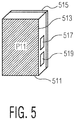
- FIG. 5 depicts a control and/or display unit 511.
- Control and/or display unit 511 has two plates 513 and 515 on opposite sides that function as the coupling capacitor CE1.
- Control and/or display unit 511 may be held in the hand of a user.
- One of the plates, 513 or 515 will be held more securely in the hand than the other and will therefore be more strongly coupled to the user's body, while the other plate will have a somewhat stronger coupling to the environment.
- Control and/or display unit 511 is capable of communicating with transmitter XMTR or receiver RCVR.
- control and/or display unit may, in combination, or individually, provide: volume control; noise reduction control; human body parameters such as heart rate, and other items such as physical parameters monitored around the body. Operation of the control and/or display unit is facilitated by the electromagnetic induction fields.
- dimensioning and parallelism of the plates 513 and 515 of coupling capacitor CE1 are similar to that described above.
- Control and/or display unit may have a display 517, and internal circuitry, 519, similar to either transmitter XMTR or receiver RCVR (or may have internal circuitry which is a transceiver as previously described).
Landscapes
- Engineering & Computer Science (AREA)
- Computer Networks & Wireless Communication (AREA)
- Signal Processing (AREA)
- Physics & Mathematics (AREA)
- General Physics & Mathematics (AREA)
- Power Engineering (AREA)
- Near-Field Transmission Systems (AREA)
Claims (14)
- Système d'émetteur-récepteur sans fil à induction électromagnétique (300) comprenant :
un émetteur-récepteur (302) comprenant :une antenne magnétique comprenant une bobine, L1 ;une antenne électrique, CE1, comprenant un condensateur connecté en parallèle à la bobine, le condensateur comprenant des première et seconde plaques, la première plaque pouvant être couplée à un corps vivant ; etun pilote de puissance, B3a, configuré pour produire un signal de modulation conformément à des données à transmettre, le signal de modulation servant à :(i) commander l'antenne magnétique, L1, pour produire un champ magnétique en champ proche, et(ii) commander l'antenne électrique, CE1, pour produire un champ électrique en champ proche, le champ électrique en champ proche pouvant être couplé au corps vivant et présentant une direction normale à la surface du corps vivant ;le système d'émetteur-récepteur sans fil à induction électromagnétique (300) comprenant en outre un second émetteur-récepteur sans fil à induction électromagnétique (304) ;dans lequel l'émetteur-récepteur (302), quand il est couplé au corps vivant à un premier emplacement du corps vivant, est configuré pour émettre par l'intermédiaire du champ magnétique en champ proche et du champ électrique en champ proche, le signal de modulation qui achemine simultanément les données et une puissance jusqu'à un second émetteur-récepteur sans fil à induction électromagnétique (304), le second émetteur-récepteur sans fil à induction électromagnétique (304) pouvant être couplé à un second emplacement du corps vivant à une distance du premier emplacement ;dans lequel, en fonctionnement, les premier et second emplacements sont connectés par à la fois un couplage en champ proche magnétique à partir de l'antenne magnétique, L1, et un couplage en champ proche électrique à partir de l'antenne électrique, CE1 ; etdans lequel en fonctionnement, le second émetteur-récepteur sans fil à induction électromagnétique (304) est configuré pour recevoir le signal de modulation et le convertir en une puissance de courant continu, afin d'actionner le second émetteur-récepteur sans fil à induction électromagnétique (304). - Système d'émetteur-récepteur sans fil à induction électromagnétique (300) selon la revendication 1, comprenant en outre une source d'énergie connectée au pilote de puissance, B3a.
- Système d'émetteur-récepteur sans fil à induction électromagnétique (300) selon la revendication 2, dans lequel la source d'énergie comprend un d'une batterie, d'un collecteur d'énergie solaire, ou d'un collecteur d'énergie cinétique.
- Système d'émetteur-récepteur sans fil à induction électromagnétique (300) selon n'importe quelle revendication précédente, comprenant en outre une unité d'adaptation adaptable, C3a, connectée au pilote de puissance, B3a.
- Système d'émetteur-récepteur sans fil à induction électromagnétique (300) selon la revendication 4, dans lequel l'unité d'adaptation adaptable, C3a, comprend une interface avec les antennes.
- Système d'émetteur-récepteur sans fil à induction électromagnétique (300) selon l'une ou l'autre des revendications 4 ou 5, dans lequel l'unité d'adaptation adaptable, C3a, réalise une adaptation conjuguée du pilote de puissance, B3a, et des antennes.
- Système d'émetteur-récepteur sans fil à induction électromagnétique (300) selon n'importe quelle revendication précédente, comprenant en outre une unité radio connectée à l'antenne électrique et à l'antenne magnétique.
- Système d'émetteur-récepteur sans fil à induction électromagnétique (300) selon n'importe quelle revendication précédente, comprenant en outre un dispositif de source de musique comprenant l'émetteur-récepteur sans fil à induction électromagnétique.
- Système d'émetteur-récepteur sans fil à induction électromagnétique (300) selon la revendication 8, comprenant en outre un dispositif de haut-parleur sans fil comprenant le second émetteur-récepteur sans fil à induction électromagnétique (304).
- Système d'émetteur-récepteur sans fil à induction électromagnétique (300) selon la revendication 9, dans lequel le dispositif de haut-parleur sans fil comprend des écouteurs boutons.
- Emetteur-récepteur sans fil à induction électromagnétique (304) comprenant :une antenne magnétique comprenant une bobine, L1, configurée pour recevoir un champ magnétique en champ proche ;une antenne électrique, CE2, comprenant un condensateur connecté en parallèle à la bobine et configuré pour recevoir un champ électrique en champ proche, le condensateur comprenant des première et seconde plaques, la première plaque pouvant être couplée à un corps vivant ; etun récepteur configuré pour recevoir un signal de modulation acheminé par le champ magnétique en champ proche et le champ électrique en champ proche, le signal de modulation ayant été modulé conformément à des données à transmettre ;dans lequel l'émetteur-récepteur sans fil à induction électromagnétique (304), lorsqu'il est couplé au corps vivant à un premier emplacement du corps vivant, est configuré pour recevoir des données et une puissance à partir d'un second émetteur-récepteur sans fil à induction électromagnétique (302) pouvant être couplé à un second emplacement du corps vivant à une distance du premier emplacement, les données et la puissance étant acheminées vers l'émetteur-récepteur sans fil à induction électromagnétique (304) par le signal de modulation, par l'intermédiaire du champ magnétique en champ proche et du champ électrique en champ proche, à partir du second émetteur-récepteur sans fil à induction électromagnétique (302) ; etdans lequel, en fonctionnement, les premier et second emplacements sont connectés par à la fois un couplage en champ proche magnétique à partir de l'antenne magnétique et un couplage en champ proche électrique à partir de l'antenne électrique, CE2 ; etdans lequel en fonctionnement, le second émetteur-récepteur sans fil à induction électromagnétique (304) est configurée pour recevoir le signal de modulation et le convertir en une puissance de courant continu, afin d'actionner l'émetteur-récepteur sans fil à induction électromagnétique (304).
- Emetteur-récepteur sans fil à induction électromagnétique (304) selon la revendication 11, comprenant en outre un circuit d'accord configuré pour accorder une combinaison d'antennes, la combinaison d'antennes comprenant l'antenne magnétique et l'antenne électrique, CE2.
- Emetteur-récepteur sans fil à induction électromagnétique (304) selon l'une ou l'autre des revendications 11 ou 12, comprenant en outre un contrôleur (511) comprenant une unité de traitement de données et une unité de traitement de signaux, le contrôleur (511) commandant le fonctionnement du récepteur.
- Emetteur-récepteur sans fil à induction électromagnétique (304) selon l'une quelconque des revendications 11 à 13, comprenant en outre un dispositif de haut-parleur sans fil couplé à l'émetteur récepteur.
Applications Claiming Priority (3)
| Application Number | Priority Date | Filing Date | Title |
|---|---|---|---|
| US14/270,013 US10015604B2 (en) | 2014-05-05 | 2014-05-05 | Electromagnetic induction field communication |
| US14/302,791 US9197986B1 (en) | 2014-06-12 | 2014-06-12 | Electromagnetic induction radio |
| US14/569,024 US10009069B2 (en) | 2014-05-05 | 2014-12-12 | Wireless power delivery and data link |
Publications (2)
| Publication Number | Publication Date |
|---|---|
| EP2942876A1 EP2942876A1 (fr) | 2015-11-11 |
| EP2942876B1 true EP2942876B1 (fr) | 2020-11-11 |
Family
ID=52991640
Family Applications (1)
| Application Number | Title | Priority Date | Filing Date |
|---|---|---|---|
| EP15164621.3A Active EP2942876B1 (fr) | 2014-05-05 | 2015-04-22 | Apport de puissance sans fil et liaison de données |
Country Status (2)
| Country | Link |
|---|---|
| US (1) | US10009069B2 (fr) |
| EP (1) | EP2942876B1 (fr) |
Families Citing this family (31)
| Publication number | Priority date | Publication date | Assignee | Title |
|---|---|---|---|---|
| US20120203620A1 (en) | 2010-11-08 | 2012-08-09 | Douglas Howard Dobyns | Techniques For Wireless Communication Of Proximity Based Marketing |
| US8929809B2 (en) | 2011-03-22 | 2015-01-06 | Radeum, Inc. | Techniques for wireless communication of proximity based content |
| US8880100B2 (en) | 2011-03-23 | 2014-11-04 | Radium, Inc. | Proximity based social networking |
| US10014578B2 (en) | 2014-05-05 | 2018-07-03 | Nxp B.V. | Body antenna system |
| US9819075B2 (en) | 2014-05-05 | 2017-11-14 | Nxp B.V. | Body communication antenna |
| US9812788B2 (en) | 2014-11-24 | 2017-11-07 | Nxp B.V. | Electromagnetic field induction for inter-body and transverse body communication |
| US10015604B2 (en) | 2014-05-05 | 2018-07-03 | Nxp B.V. | Electromagnetic induction field communication |
| US9819395B2 (en) | 2014-05-05 | 2017-11-14 | Nxp B.V. | Apparatus and method for wireless body communication |
| US10502865B2 (en) * | 2014-07-29 | 2019-12-10 | GroGuru, Inc. | Sensing system and method for use in electromagnetic-absorbing material |
| US9705564B2 (en) | 2014-08-29 | 2017-07-11 | Freelinc Technologies | Spatially enabled secure communications |
| US10164685B2 (en) | 2014-12-31 | 2018-12-25 | Freelinc Technologies Inc. | Spatially aware wireless network |
| KR102496942B1 (ko) * | 2015-08-24 | 2023-02-06 | 더 리젠츠 오브 더 유니버시티 오브 캘리포니아 | 저전력 자기장 신체 영역 네트워크 |
| US9819097B2 (en) | 2015-08-26 | 2017-11-14 | Nxp B.V. | Antenna system |
| JP2017184091A (ja) * | 2016-03-31 | 2017-10-05 | ソニー株式会社 | 通信装置、および通信システム |
| US10320086B2 (en) | 2016-05-04 | 2019-06-11 | Nxp B.V. | Near-field electromagnetic induction (NFEMI) antenna |
| US10530177B2 (en) * | 2017-03-09 | 2020-01-07 | Cochlear Limited | Multi-loop implant charger |
| US10622729B2 (en) * | 2018-05-25 | 2020-04-14 | Nxp B.V. | Near-field antenna |
| DE102018212957B3 (de) | 2018-08-02 | 2020-01-02 | Fraunhofer-Gesellschaft zur Förderung der angewandten Forschung e.V. | Übertragung von daten von einem benutzerendgerät zu einem anderen gerät |
| DE102018214716A1 (de) | 2018-08-30 | 2020-03-05 | Fraunhofer-Gesellschaft zur Förderung der angewandten Forschung e.V. | Übertragung von daten zwischen einem benutzerendgerät und einem anderen gerät |
| US10992392B2 (en) * | 2018-09-06 | 2021-04-27 | Nxp B.V. | Near-field electromagnetic induction (NFEMI) ratio control |
| DE102019201152B3 (de) | 2019-01-30 | 2020-06-18 | Fraunhofer-Gesellschaft zur Förderung der angewandten Forschung e.V. | Bidirektionale Konfiguration von Sensorknoten mit Mobiltelefon ohne Erweiterung |
| CN109891761A (zh) * | 2019-01-31 | 2019-06-14 | 深圳市汇顶科技股份有限公司 | 传输信息的方法、通信装置、便携式设备和通信系统 |
| US12573882B2 (en) * | 2019-03-12 | 2026-03-10 | Daanaa Resolution Inc. | Power transfer system and methods |
| TW202527420A (zh) | 2019-03-12 | 2025-07-01 | 加拿大商達納解析公司 | 功率轉移系統及方法 |
| CN109941128B (zh) * | 2019-04-25 | 2020-12-01 | 西南交通大学 | 一种电场耦合式的电动汽车无线充电技术电压优化方法 |
| DE102019206836A1 (de) | 2019-05-10 | 2020-11-12 | Fraunhofer-Gesellschaft zur Förderung der angewandten Forschung e.V. | Effiziente Kommunikation zur Konfiguration von Sensorknoten |
| EP3766717B1 (fr) | 2019-07-19 | 2023-09-06 | Nxp B.V. | Dispositif audible mobile et système de commande de véhicule |
| US11296750B2 (en) * | 2020-05-12 | 2022-04-05 | Nxp B.V. | Near-field wireless device including a first near-field antenna and a second near-field antenna |
| US11418235B2 (en) * | 2020-11-10 | 2022-08-16 | Nxp B.V. | Variable ratio near field wireless device |
| CN116745993A (zh) | 2021-02-26 | 2023-09-12 | 华为技术有限公司 | 天线装置和通信方法 |
| FR3146245B1 (fr) * | 2023-02-24 | 2025-01-10 | Continental Automotive Tech Gmbh | Procede de detection d’un objet a charger sur un dispositif de charge et dispositif de charge associe |
Citations (2)
| Publication number | Priority date | Publication date | Assignee | Title |
|---|---|---|---|---|
| US6992565B1 (en) * | 1998-09-14 | 2006-01-31 | Koninklijke Philips Electronics N.V. | Electronic communications system |
| EP2019993A1 (fr) * | 2006-05-04 | 2009-02-04 | Nxp B.V. | Dispositif de communication et circuit électrique pour un dispositif de communication |
Family Cites Families (123)
| Publication number | Priority date | Publication date | Assignee | Title |
|---|---|---|---|---|
| US3766476A (en) | 1971-05-21 | 1973-10-16 | United Communications Ind Inc | Highway radio communication system |
| JPS5850078B2 (ja) * | 1979-05-04 | 1983-11-08 | 株式会社 弦エンジニアリング | 振動ピックアップ型イヤ−マイクロホンの送信装置および送受信装置 |
| US4692743A (en) | 1984-04-06 | 1987-09-08 | Holden Harold C | Alarm system |
| US5673054A (en) | 1991-05-09 | 1997-09-30 | Seiko Epson Corporation | Antenna and miniature portable wireless transceiver |
| CA2220294C (fr) | 1995-05-08 | 2002-07-09 | Massachusetts Institute Of Technology | Dispositif de detection sans contact et de signalisation par courants intra-corporels induits par une source exterieure |
| US5737019A (en) | 1996-01-29 | 1998-04-07 | Matsushita Electric Corporation Of America | Method and apparatus for changing resolution by direct DCT mapping |
| US5708732A (en) | 1996-03-06 | 1998-01-13 | Hewlett-Packard Company | Fast DCT domain downsampling and inverse motion compensation |
| FR2748360B1 (fr) * | 1996-05-03 | 1998-06-26 | Ebauchesfabrik Eta Ag | Dispositif de reception et/ou d'emission de messages radio-diffuses portatif comportant une antenne inductive et capacitive |
| US6223018B1 (en) | 1996-12-12 | 2001-04-24 | Nippon Telegraph And Telephone Corporation | Intra-body information transfer device |
| US6211799B1 (en) * | 1997-11-06 | 2001-04-03 | Massachusetts Institute Of Technology | Method and apparatus for transbody transmission of power and information |
| US6104913A (en) | 1998-03-11 | 2000-08-15 | Bell Atlantic Network Services, Inc. | Personal area network for personal telephone services |
| US6275737B1 (en) * | 1998-10-14 | 2001-08-14 | Advanced Bionics Corporation | Transcutaneous transmission pouch |
| US5948006A (en) * | 1998-10-14 | 1999-09-07 | Advanced Bionics Corporation | Transcutaneous transmission patch |
| US6424820B1 (en) | 1999-04-02 | 2002-07-23 | Interval Research Corporation | Inductively coupled wireless system and method |
| DK1247423T3 (da) | 2000-01-13 | 2003-11-03 | Phonak Ag | Høreapparatfjernregulering og høreapparat med en fjernregulering af denne type |
| US6754472B1 (en) | 2000-04-27 | 2004-06-22 | Microsoft Corporation | Method and apparatus for transmitting power and data using the human body |
| US7206423B1 (en) | 2000-05-10 | 2007-04-17 | Board Of Trustees Of University Of Illinois | Intrabody communication for a hearing aid |
| US6529169B2 (en) | 2000-07-06 | 2003-03-04 | C. Crane Company, Inc. | Twin coil antenna |
| US7254246B2 (en) | 2001-03-13 | 2007-08-07 | Phonak Ag | Method for establishing a binaural communication link and binaural hearing devices |
| US7170932B2 (en) | 2001-05-11 | 2007-01-30 | Mitsubishi Electric Research Laboratories, Inc. | Video transcoder with spatial resolution reduction and drift compensation |
| US7295872B2 (en) | 2001-10-10 | 2007-11-13 | Massachusetts Institute Of Technology | System for and method of power efficient electrical tissue stimulation |
| CN101448162B (zh) | 2001-12-17 | 2013-01-02 | 微软公司 | 处理视频图像的方法 |
| US6890719B2 (en) | 2002-05-10 | 2005-05-10 | The Board Of Trustess Of The University Of Illinois | Fluorescence based biosensor |
| US6781551B2 (en) | 2002-08-06 | 2004-08-24 | Phonak Ag | Hand-held transmitter and/or receiver unit |
| US7512448B2 (en) | 2003-01-10 | 2009-03-31 | Phonak Ag | Electrode placement for wireless intrabody communication between components of a hearing system |
| DE10305830B3 (de) | 2003-02-12 | 2004-10-21 | Siemens Audiologische Technik Gmbh | Vorrichtung und Verfahren zum Fernbedienen eines Hörgeräts |
| US7203237B2 (en) | 2003-09-17 | 2007-04-10 | Texas Instruments Incorporated | Transcoders and methods |
| US20050075696A1 (en) * | 2003-10-02 | 2005-04-07 | Medtronic, Inc. | Inductively rechargeable external energy source, charger, system and method for a transcutaneous inductive charger for an implantable medical device |
| US8442108B2 (en) | 2004-07-12 | 2013-05-14 | Microsoft Corporation | Adaptive updates in motion-compensated temporal filtering |
| US8374238B2 (en) | 2004-07-13 | 2013-02-12 | Microsoft Corporation | Spatial scalability in 3D sub-band decoding of SDMCTF-encoded video |
| KR100727817B1 (ko) | 2004-09-07 | 2007-06-13 | 한국전자통신연구원 | 인체를 매질로 이용한 통신장치 및 그 방법 |
| US7449372B2 (en) | 2004-12-17 | 2008-11-11 | Semiconductor Energy Laboratory Co., Ltd. | Manufacturing method of substrate having conductive layer and manufacturing method of semiconductor device |
| US20060233258A1 (en) | 2005-04-15 | 2006-10-19 | Microsoft Corporation | Scalable motion estimation |
| JP4586618B2 (ja) | 2005-04-18 | 2010-11-24 | ソニー株式会社 | 人体通信システム及び通信装置 |
| JP4257611B2 (ja) | 2005-05-17 | 2009-04-22 | ソニー株式会社 | 通信装置および方法、並びにプログラム |
| JP2006350990A (ja) | 2005-05-17 | 2006-12-28 | Sony Corp | 情報処理システム、および情報処理方法 |
| US7783067B1 (en) | 2005-08-11 | 2010-08-24 | At&T Mobility Ii Llc | System and method for enhancing the inductive coupling between a hearing aid operating in telecoil mode and a communication device |
| US20070058713A1 (en) | 2005-09-14 | 2007-03-15 | Microsoft Corporation | Arbitrary resolution change downsizing decoder |
| US7773943B2 (en) | 2005-11-04 | 2010-08-10 | Motorola, Inc. | Hearing aid compatibility mode switching for a mobile station |
| KR100725228B1 (ko) | 2005-12-16 | 2007-06-04 | 한국과학기술원 | 인체를 이용한 데이터 통신 장치 및 모듈 |
| JP4997250B2 (ja) | 2005-12-19 | 2012-08-08 | エヌエックスピー ビー ヴィ | 無線レシーバ、無線トランスミッタおよび補聴器 |
| KR101227678B1 (ko) | 2006-02-10 | 2013-01-30 | 삼성전자주식회사 | 인체 통신 시스템 및 방법 |
| US8358785B2 (en) | 2006-05-30 | 2013-01-22 | Siemens Audiologische Technik Gmbh | Hearing system with wideband pulse transmitter |
| KR100799571B1 (ko) | 2006-06-20 | 2008-01-30 | 한국전자통신연구원 | 인체를 이용한 통신장치 및 그 방법 |
| EP2047714A1 (fr) * | 2006-07-28 | 2009-04-15 | Siemens Audiologische Technik GmbH | Système d'antenne pour applications de dispositif auditif |
| US8605924B2 (en) | 2006-12-11 | 2013-12-10 | Siemens Audiologische Technik Gmbh | Hearing apparatus including transponder detection and corresponding control method |
| US8237622B2 (en) | 2006-12-28 | 2012-08-07 | Philtech Inc. | Base sheet |
| CA2576615C (fr) | 2007-02-01 | 2012-01-03 | Emma Mixed Signal C.V. | Rayonnement et conductivite corporels en communication rf |
| US7796943B2 (en) | 2007-03-28 | 2010-09-14 | Lockheed Martin Corporation | Sub-surface communications system and method |
| EP1981176A1 (fr) * | 2007-04-11 | 2008-10-15 | Oticon A/S | Dispositif de communication sans fil pour couplage inductif sur un autre dispositif |
| US20080262376A1 (en) | 2007-04-17 | 2008-10-23 | Proactive Health Devices, Inc. | Wireless sensor system for monitoring skin condition using the body as communication conduit |
| KR100871842B1 (ko) | 2007-05-02 | 2008-12-03 | 한국전자통신연구원 | 인체통신에서 접지전극의 인체접촉 제어 장치 및 그방법과, 그를 이용한 인체통신 시스템 |
| EP2171860B1 (fr) | 2007-06-27 | 2011-08-10 | Nxp B.V. | Émetteur à niveau d'émission réglable pour liaison magnétique |
| US8175306B2 (en) | 2007-07-06 | 2012-05-08 | Cochlear Limited | Wireless communication between devices of a hearing prosthesis |
| WO2009021220A1 (fr) * | 2007-08-08 | 2009-02-12 | Radeum, Inc. | Système de communication en champ proche à sécurité améliorée |
| US9002263B2 (en) | 2007-12-20 | 2015-04-07 | Koninklijke Philips N.V. | Switching between multiple coupling modes |
| DE102008008898B3 (de) | 2008-02-13 | 2009-05-20 | Siemens Medical Instruments Pte. Ltd. | Verfahren und Vorrichtung zum Überwachen einer Hörhilfe |
| US8415777B2 (en) | 2008-02-29 | 2013-04-09 | Broadcom Corporation | Integrated circuit with millimeter wave and inductive coupling and methods for use therewith |
| JP5267463B2 (ja) | 2008-03-03 | 2013-08-21 | 株式会社村田製作所 | 無線icデバイス及び無線通信システム |
| US8711948B2 (en) | 2008-03-21 | 2014-04-29 | Microsoft Corporation | Motion-compensated prediction of inter-layer residuals |
| WO2009124045A1 (fr) | 2008-03-31 | 2009-10-08 | Cochlear Americas | Système de microphone implantable |
| JP5290633B2 (ja) | 2008-06-13 | 2013-09-18 | セミコンダクター・コンポーネンツ・インダストリーズ・リミテッド・ライアビリティ・カンパニー | 通信システム及びそれに用いられる受信装置 |
| US8773269B2 (en) | 2008-06-27 | 2014-07-08 | Neal T. RICHARDSON | Autonomous fall monitor |
| US8111042B2 (en) | 2008-08-05 | 2012-02-07 | Broadcom Corporation | Integrated wireless resonant power charging and communication channel |
| US8421274B2 (en) * | 2008-09-12 | 2013-04-16 | University Of Pittsburgh-Of The Commonwealth System Of Higher Education | Wireless energy transfer system |
| WO2010042020A1 (fr) * | 2008-10-10 | 2010-04-15 | Milux Holding Sa | Procédé et appareil permettant de fournir de l'énergie à un implant |
| KR20100075353A (ko) | 2008-12-24 | 2010-07-02 | 한국전자통신연구원 | 인체영역 네트워크에서 인체의 일부를 안테나로 이용하는 통신 시스템 및 방법 |
| US9083391B2 (en) | 2011-01-20 | 2015-07-14 | Triune Systems, LLC | Wireless power transceiver system |
| EP2568417B1 (fr) | 2009-04-21 | 2018-07-04 | Murata Manufacturing Co., Ltd. | Dispositif d'antenne et procédé de réglage de fréquence de résonance du dispositif d'antenne |
| KR101590043B1 (ko) | 2009-05-18 | 2016-02-01 | 삼성전자주식회사 | 인체 통신을 이용한 기능 수행 방법 및 그를 수행하는 단말기 |
| US8571486B2 (en) | 2009-05-28 | 2013-10-29 | Rockwell Automation Technologies, Inc. | Wireless user interface system performance monitoring |
| JP5271183B2 (ja) | 2009-07-22 | 2013-08-21 | アルプス電気株式会社 | 通信装置及び通信方法 |
| DE102009035386B4 (de) | 2009-07-30 | 2011-12-15 | Cochlear Ltd. | Hörhilfeimplantat |
| EP2476266B1 (fr) * | 2009-09-08 | 2016-07-06 | Sivantos Pte. Ltd. | Prothèse auditive à capacité de charger de manière sans fil une batterie |
| WO2011055703A1 (fr) | 2009-11-04 | 2011-05-12 | 株式会社村田製作所 | Terminal de communication et système de traitement de l'information |
| DK2352312T3 (da) | 2009-12-03 | 2013-10-21 | Oticon As | Fremgangsmåde til dynamisk undertrykkelse af omgivende akustisk støj, når der lyttes til elektriske input |
| CN102195366B (zh) * | 2010-03-19 | 2014-03-12 | Tdk株式会社 | 无线馈电装置以及无线电力传输系统 |
| US8909966B2 (en) * | 2010-03-26 | 2014-12-09 | Advantest Corporation | Wireless power supply apparatus |
| EP2375534A1 (fr) * | 2010-04-09 | 2011-10-12 | Nxp B.V. | Appareil de transfert d'énergie vers un accumulateur et système pour charger un accumulateur électrique |
| KR101306897B1 (ko) | 2010-04-12 | 2013-09-10 | 가부시키가이샤 무라타 세이사쿠쇼 | 안테나 장치 및 통신 단말장치 |
| EP2381700B1 (fr) | 2010-04-20 | 2015-03-11 | Oticon A/S | Déréverbération de signal utilisant les informations d'environnement |
| EP2393215B1 (fr) * | 2010-06-03 | 2015-10-21 | Nxp B.V. | Circuits de réception et d'émission radio, et procédés correspondants |
| JP2012039370A (ja) | 2010-08-06 | 2012-02-23 | Sony Corp | 通信システム並びに通信装置 |
| EP2628210B1 (fr) * | 2010-10-12 | 2019-01-09 | GN Hearing A/S | Prothese auditive comprenant un dispositif d'antenne |
| EP2458674A3 (fr) | 2010-10-12 | 2014-04-09 | GN ReSound A/S | Système d'antenne pour aide auditive |
| DK2630811T3 (en) | 2010-10-19 | 2016-02-08 | Sonova Ag | A hearing instrument, comprising a rechargeable power source |
| CN102013895B (zh) | 2010-12-13 | 2013-06-19 | 惠州硕贝德无线科技股份有限公司 | 一种解决小型终端手机天线的电磁兼容性方法 |
| US8929809B2 (en) | 2011-03-22 | 2015-01-06 | Radeum, Inc. | Techniques for wireless communication of proximity based content |
| US8918197B2 (en) | 2012-06-13 | 2014-12-23 | Avraham Suhami | Audio communication networks |
| WO2012153690A1 (fr) | 2011-05-09 | 2012-11-15 | 株式会社村田製作所 | Circuit de réglage de degré de couplage, antenne et terminal de communication associés |
| FR2977098B1 (fr) | 2011-06-21 | 2016-06-24 | Tekcem | Emetteur pour transmission multivoie puce-a-puce en champ proche |
| US8970446B2 (en) | 2011-07-01 | 2015-03-03 | Apple Inc. | Electronic device with magnetic antenna mounting |
| CA2876622C (fr) | 2011-08-01 | 2018-06-05 | Fred Bergman Healthcare Pty Ltd | Capteur d'humidite capacitif et procede de fabrication associe |
| US9160079B2 (en) | 2011-09-14 | 2015-10-13 | William N. Carr | Compact multi-band antenna |
| US8908894B2 (en) | 2011-12-01 | 2014-12-09 | At&T Intellectual Property I, L.P. | Devices and methods for transferring data through a human body |
| US8831256B2 (en) * | 2011-12-09 | 2014-09-09 | Cochlear Limited | Controlling a link for different load conditions |
| JP5924050B2 (ja) * | 2012-03-16 | 2016-05-25 | ソニー株式会社 | 給電装置、受電装置、給電方法、受電方法、およびプログラム |
| JP5814854B2 (ja) | 2012-04-18 | 2015-11-17 | 株式会社東芝 | 通信装置 |
| US9874615B2 (en) | 2012-04-19 | 2018-01-23 | New York University | Dipole array arrangement |
| EP2662800B1 (fr) * | 2012-05-07 | 2014-11-05 | ST-Ericsson SA | Lecteur NFC avec champ magnétique constant |
| JP5757345B2 (ja) | 2012-06-04 | 2015-07-29 | 株式会社村田製作所 | 無線通信装置 |
| US8878735B2 (en) | 2012-06-25 | 2014-11-04 | Gn Resound A/S | Antenna system for a wearable computing device |
| US20140023216A1 (en) * | 2012-07-17 | 2014-01-23 | Starkey Laboratories, Inc. | Hearing assistance device with wireless communication for on- and off- body accessories |
| JPWO2014030317A1 (ja) | 2012-08-24 | 2016-07-28 | パナソニックヘルスケアホールディングス株式会社 | 人体通信装置、通信機器及び通信方法 |
| CN103024621B (zh) | 2012-11-16 | 2015-08-05 | 青岛歌尔声学科技有限公司 | 一种蓝牙耳机和利用蓝牙耳机通信的方法 |
| US9281118B2 (en) | 2012-12-10 | 2016-03-08 | Intel Corporation | Cascaded coils for multi-surface coverage in near field communication |
| US9276639B2 (en) * | 2013-02-25 | 2016-03-01 | Apple Inc. | Wirelessly charged electronic device with shared inductor circuitry |
| US20140320369A1 (en) | 2013-04-24 | 2014-10-30 | Broadcom Corporation | Shielding layer for a device having a plurality of antennas |
| US9673868B2 (en) * | 2013-05-16 | 2017-06-06 | Microchip Technology Incorporated | Wireless door lock power transfer system having communications capabilities |
| JP6379660B2 (ja) * | 2013-06-27 | 2018-08-29 | Tdk株式会社 | ワイヤレス受電装置、及び、ワイヤレス電力伝送装置 |
| JP2015032928A (ja) | 2013-08-01 | 2015-02-16 | 株式会社東芝 | 生体通信装置 |
| JP2015032927A (ja) | 2013-08-01 | 2015-02-16 | 株式会社東芝 | 生体検出センサ、生体検出センサを備えた装置、金属検出センサ |
| KR20150019252A (ko) | 2013-08-13 | 2015-02-25 | 삼성전기주식회사 | Nfc 안테나 모듈 |
| EP2843846B1 (fr) * | 2013-08-30 | 2020-01-01 | Airbus Operations GmbH | Procédé et dispositif de communication avec un dispositif électronique personnel dans un aéronef |
| GB2519079B (en) * | 2013-10-08 | 2020-11-04 | Nokia Technologies Oy | Method and apparatus for wireless power transfer |
| US9197986B1 (en) | 2014-06-12 | 2015-11-24 | Nxp, B.V. | Electromagnetic induction radio |
| US10014578B2 (en) | 2014-05-05 | 2018-07-03 | Nxp B.V. | Body antenna system |
| US9819395B2 (en) | 2014-05-05 | 2017-11-14 | Nxp B.V. | Apparatus and method for wireless body communication |
| US10015604B2 (en) | 2014-05-05 | 2018-07-03 | Nxp B.V. | Electromagnetic induction field communication |
| US9819075B2 (en) | 2014-05-05 | 2017-11-14 | Nxp B.V. | Body communication antenna |
| US9774087B2 (en) | 2014-05-30 | 2017-09-26 | Apple Inc. | Wireless electronic device with magnetic shielding layer |
| KR101594380B1 (ko) | 2015-03-04 | 2016-02-16 | 엘지전자 주식회사 | 이동 단말기 및 코일 안테나 모듈 |
| TWI558568B (zh) | 2015-11-03 | 2016-11-21 | 行政院原子能委員會核能研究所 | 透氣金屬基板、金屬支撐固態氧化物燃料電池及其製作方法 |
-
2014
- 2014-12-12 US US14/569,024 patent/US10009069B2/en active Active
-
2015
- 2015-04-22 EP EP15164621.3A patent/EP2942876B1/fr active Active
Patent Citations (2)
| Publication number | Priority date | Publication date | Assignee | Title |
|---|---|---|---|---|
| US6992565B1 (en) * | 1998-09-14 | 2006-01-31 | Koninklijke Philips Electronics N.V. | Electronic communications system |
| EP2019993A1 (fr) * | 2006-05-04 | 2009-02-04 | Nxp B.V. | Dispositif de communication et circuit électrique pour un dispositif de communication |
Also Published As
| Publication number | Publication date |
|---|---|
| US20150318896A1 (en) | 2015-11-05 |
| EP2942876A1 (fr) | 2015-11-11 |
| US10009069B2 (en) | 2018-06-26 |
Similar Documents
| Publication | Publication Date | Title |
|---|---|---|
| US10009069B2 (en) | Wireless power delivery and data link | |
| US8634773B2 (en) | Short range communications for body contacting devices | |
| EP3136614B1 (fr) | Système d'antenne en champ proche | |
| EP2942878B1 (fr) | Antenne de communication à travers le corps humain | |
| US9819395B2 (en) | Apparatus and method for wireless body communication | |
| US9847677B1 (en) | Wireless charging and powering of healthcare gadgets and sensors | |
| US20190246222A1 (en) | Acoustic output device with antenna | |
| US10014578B2 (en) | Body antenna system | |
| US20070010295A1 (en) | Power transmission system, apparatus and method with communication | |
| US20130223664A1 (en) | Device with Combined Antenna and Transducer | |
| US20160339257A1 (en) | System and Method for Transmission of Electrical Signals in Imperfectly Conducting Media | |
| CN110087158A (zh) | 一种助听器 | |
| US12413918B2 (en) | Hearing device with decoupler | |
| EP3201785B1 (fr) | Dispositif de communication et système pour effectuer une communication de données à l'aide d'un corps humain ou animal en tant que moyen de transmission | |
| CN114759689B (zh) | 无线供电装置 | |
| Jang et al. | Understanding body channel communication: a review: from history to the future applications | |
| CN103036531A (zh) | 用于电短天线的rf发射器 | |
| CN105099525A (zh) | 躯体通信天线 | |
| Koshiji et al. | Wireless body area communication using electromagnetic resonance coupling | |
| US20250379663A1 (en) | Communication system for data transfer using human body resonance | |
| CN110112553B (zh) | 一种小尺寸的超宽带可植入天线 | |
| EP3139816A1 (fr) | Induction de champ électromagnétique pour communication de corps transversale ou entre corps | |
| Masouleh et al. | Recent advances in wireless systems for simultaneous power and data transfer | |
| Baek et al. | Conductive power transmission for implantable devices | |
| GB2584814A (en) | Multiband wireless charging apparatus |
Legal Events
| Date | Code | Title | Description |
|---|---|---|---|
| PUAI | Public reference made under article 153(3) epc to a published international application that has entered the european phase |
Free format text: ORIGINAL CODE: 0009012 |
|
| AK | Designated contracting states |
Kind code of ref document: A1 Designated state(s): AL AT BE BG CH CY CZ DE DK EE ES FI FR GB GR HR HU IE IS IT LI LT LU LV MC MK MT NL NO PL PT RO RS SE SI SK SM TR |
|
| AX | Request for extension of the european patent |
Extension state: BA ME |
|
| 17P | Request for examination filed |
Effective date: 20160511 |
|
| RBV | Designated contracting states (corrected) |
Designated state(s): AL AT BE BG CH CY CZ DE DK EE ES FI FR GB GR HR HU IE IS IT LI LT LU LV MC MK MT NL NO PL PT RO RS SE SI SK SM TR |
|
| STAA | Information on the status of an ep patent application or granted ep patent |
Free format text: STATUS: REQUEST FOR EXAMINATION WAS MADE |
|
| R17P | Request for examination filed (corrected) |
Effective date: 20160511 |
|
| STAA | Information on the status of an ep patent application or granted ep patent |
Free format text: STATUS: EXAMINATION IS IN PROGRESS |
|
| 17Q | First examination report despatched |
Effective date: 20190125 |
|
| REG | Reference to a national code |
Ref country code: DE Ref legal event code: R079 Ref document number: 602015061770 Country of ref document: DE Free format text: PREVIOUS MAIN CLASS: H04B0005000000 Ipc: H02J0007020000 |
|
| RIC1 | Information provided on ipc code assigned before grant |
Ipc: H02J 5/00 20160101ALI20200429BHEP Ipc: H02J 7/02 20160101AFI20200429BHEP Ipc: H04B 5/00 20060101ALI20200429BHEP |
|
| GRAP | Despatch of communication of intention to grant a patent |
Free format text: ORIGINAL CODE: EPIDOSNIGR1 |
|
| STAA | Information on the status of an ep patent application or granted ep patent |
Free format text: STATUS: GRANT OF PATENT IS INTENDED |
|
| INTG | Intention to grant announced |
Effective date: 20200617 |
|
| GRAS | Grant fee paid |
Free format text: ORIGINAL CODE: EPIDOSNIGR3 |
|
| GRAA | (expected) grant |
Free format text: ORIGINAL CODE: 0009210 |
|
| STAA | Information on the status of an ep patent application or granted ep patent |
Free format text: STATUS: THE PATENT HAS BEEN GRANTED |
|
| AK | Designated contracting states |
Kind code of ref document: B1 Designated state(s): AL AT BE BG CH CY CZ DE DK EE ES FI FR GB GR HR HU IE IS IT LI LT LU LV MC MK MT NL NO PL PT RO RS SE SI SK SM TR |
|
| REG | Reference to a national code |
Ref country code: GB Ref legal event code: FG4D |
|
| REG | Reference to a national code |
Ref country code: CH Ref legal event code: EP |
|
| REG | Reference to a national code |
Ref country code: AT Ref legal event code: REF Ref document number: 1334374 Country of ref document: AT Kind code of ref document: T Effective date: 20201115 |
|
| REG | Reference to a national code |
Ref country code: DE Ref legal event code: R096 Ref document number: 602015061770 Country of ref document: DE |
|
| REG | Reference to a national code |
Ref country code: IE Ref legal event code: FG4D |
|
| REG | Reference to a national code |
Ref country code: NL Ref legal event code: MP Effective date: 20201111 |
|
| REG | Reference to a national code |
Ref country code: AT Ref legal event code: MK05 Ref document number: 1334374 Country of ref document: AT Kind code of ref document: T Effective date: 20201111 |
|
| PG25 | Lapsed in a contracting state [announced via postgrant information from national office to epo] |
Ref country code: GR Free format text: LAPSE BECAUSE OF FAILURE TO SUBMIT A TRANSLATION OF THE DESCRIPTION OR TO PAY THE FEE WITHIN THE PRESCRIBED TIME-LIMIT Effective date: 20210212 Ref country code: RS Free format text: LAPSE BECAUSE OF FAILURE TO SUBMIT A TRANSLATION OF THE DESCRIPTION OR TO PAY THE FEE WITHIN THE PRESCRIBED TIME-LIMIT Effective date: 20201111 Ref country code: FI Free format text: LAPSE BECAUSE OF FAILURE TO SUBMIT A TRANSLATION OF THE DESCRIPTION OR TO PAY THE FEE WITHIN THE PRESCRIBED TIME-LIMIT Effective date: 20201111 Ref country code: NO Free format text: LAPSE BECAUSE OF FAILURE TO SUBMIT A TRANSLATION OF THE DESCRIPTION OR TO PAY THE FEE WITHIN THE PRESCRIBED TIME-LIMIT Effective date: 20210211 Ref country code: PT Free format text: LAPSE BECAUSE OF FAILURE TO SUBMIT A TRANSLATION OF THE DESCRIPTION OR TO PAY THE FEE WITHIN THE PRESCRIBED TIME-LIMIT Effective date: 20210311 |
|
| PG25 | Lapsed in a contracting state [announced via postgrant information from national office to epo] |
Ref country code: AT Free format text: LAPSE BECAUSE OF FAILURE TO SUBMIT A TRANSLATION OF THE DESCRIPTION OR TO PAY THE FEE WITHIN THE PRESCRIBED TIME-LIMIT Effective date: 20201111 Ref country code: BG Free format text: LAPSE BECAUSE OF FAILURE TO SUBMIT A TRANSLATION OF THE DESCRIPTION OR TO PAY THE FEE WITHIN THE PRESCRIBED TIME-LIMIT Effective date: 20210211 Ref country code: PL Free format text: LAPSE BECAUSE OF FAILURE TO SUBMIT A TRANSLATION OF THE DESCRIPTION OR TO PAY THE FEE WITHIN THE PRESCRIBED TIME-LIMIT Effective date: 20201111 Ref country code: SE Free format text: LAPSE BECAUSE OF FAILURE TO SUBMIT A TRANSLATION OF THE DESCRIPTION OR TO PAY THE FEE WITHIN THE PRESCRIBED TIME-LIMIT Effective date: 20201111 Ref country code: LV Free format text: LAPSE BECAUSE OF FAILURE TO SUBMIT A TRANSLATION OF THE DESCRIPTION OR TO PAY THE FEE WITHIN THE PRESCRIBED TIME-LIMIT Effective date: 20201111 Ref country code: IS Free format text: LAPSE BECAUSE OF FAILURE TO SUBMIT A TRANSLATION OF THE DESCRIPTION OR TO PAY THE FEE WITHIN THE PRESCRIBED TIME-LIMIT Effective date: 20210311 |
|
| REG | Reference to a national code |
Ref country code: LT Ref legal event code: MG9D |
|
| PG25 | Lapsed in a contracting state [announced via postgrant information from national office to epo] |
Ref country code: HR Free format text: LAPSE BECAUSE OF FAILURE TO SUBMIT A TRANSLATION OF THE DESCRIPTION OR TO PAY THE FEE WITHIN THE PRESCRIBED TIME-LIMIT Effective date: 20201111 |
|
| PG25 | Lapsed in a contracting state [announced via postgrant information from national office to epo] |
Ref country code: SK Free format text: LAPSE BECAUSE OF FAILURE TO SUBMIT A TRANSLATION OF THE DESCRIPTION OR TO PAY THE FEE WITHIN THE PRESCRIBED TIME-LIMIT Effective date: 20201111 Ref country code: RO Free format text: LAPSE BECAUSE OF FAILURE TO SUBMIT A TRANSLATION OF THE DESCRIPTION OR TO PAY THE FEE WITHIN THE PRESCRIBED TIME-LIMIT Effective date: 20201111 Ref country code: LT Free format text: LAPSE BECAUSE OF FAILURE TO SUBMIT A TRANSLATION OF THE DESCRIPTION OR TO PAY THE FEE WITHIN THE PRESCRIBED TIME-LIMIT Effective date: 20201111 Ref country code: CZ Free format text: LAPSE BECAUSE OF FAILURE TO SUBMIT A TRANSLATION OF THE DESCRIPTION OR TO PAY THE FEE WITHIN THE PRESCRIBED TIME-LIMIT Effective date: 20201111 Ref country code: EE Free format text: LAPSE BECAUSE OF FAILURE TO SUBMIT A TRANSLATION OF THE DESCRIPTION OR TO PAY THE FEE WITHIN THE PRESCRIBED TIME-LIMIT Effective date: 20201111 Ref country code: SM Free format text: LAPSE BECAUSE OF FAILURE TO SUBMIT A TRANSLATION OF THE DESCRIPTION OR TO PAY THE FEE WITHIN THE PRESCRIBED TIME-LIMIT Effective date: 20201111 |
|
| REG | Reference to a national code |
Ref country code: DE Ref legal event code: R097 Ref document number: 602015061770 Country of ref document: DE |
|
| PG25 | Lapsed in a contracting state [announced via postgrant information from national office to epo] |
Ref country code: DK Free format text: LAPSE BECAUSE OF FAILURE TO SUBMIT A TRANSLATION OF THE DESCRIPTION OR TO PAY THE FEE WITHIN THE PRESCRIBED TIME-LIMIT Effective date: 20201111 |
|
| PLBE | No opposition filed within time limit |
Free format text: ORIGINAL CODE: 0009261 |
|
| STAA | Information on the status of an ep patent application or granted ep patent |
Free format text: STATUS: NO OPPOSITION FILED WITHIN TIME LIMIT |
|
| 26N | No opposition filed |
Effective date: 20210812 |
|
| PG25 | Lapsed in a contracting state [announced via postgrant information from national office to epo] |
Ref country code: IT Free format text: LAPSE BECAUSE OF FAILURE TO SUBMIT A TRANSLATION OF THE DESCRIPTION OR TO PAY THE FEE WITHIN THE PRESCRIBED TIME-LIMIT Effective date: 20201111 Ref country code: NL Free format text: LAPSE BECAUSE OF FAILURE TO SUBMIT A TRANSLATION OF THE DESCRIPTION OR TO PAY THE FEE WITHIN THE PRESCRIBED TIME-LIMIT Effective date: 20201111 Ref country code: AL Free format text: LAPSE BECAUSE OF FAILURE TO SUBMIT A TRANSLATION OF THE DESCRIPTION OR TO PAY THE FEE WITHIN THE PRESCRIBED TIME-LIMIT Effective date: 20201111 |
|
| PG25 | Lapsed in a contracting state [announced via postgrant information from national office to epo] |
Ref country code: SI Free format text: LAPSE BECAUSE OF FAILURE TO SUBMIT A TRANSLATION OF THE DESCRIPTION OR TO PAY THE FEE WITHIN THE PRESCRIBED TIME-LIMIT Effective date: 20201111 Ref country code: MC Free format text: LAPSE BECAUSE OF FAILURE TO SUBMIT A TRANSLATION OF THE DESCRIPTION OR TO PAY THE FEE WITHIN THE PRESCRIBED TIME-LIMIT Effective date: 20201111 Ref country code: ES Free format text: LAPSE BECAUSE OF FAILURE TO SUBMIT A TRANSLATION OF THE DESCRIPTION OR TO PAY THE FEE WITHIN THE PRESCRIBED TIME-LIMIT Effective date: 20201111 |
|
| PG25 | Lapsed in a contracting state [announced via postgrant information from national office to epo] |
Ref country code: LU Free format text: LAPSE BECAUSE OF NON-PAYMENT OF DUE FEES Effective date: 20210422 |
|
| REG | Reference to a national code |
Ref country code: BE Ref legal event code: MM Effective date: 20210430 |
|
| PG25 | Lapsed in a contracting state [announced via postgrant information from national office to epo] |
Ref country code: LI Free format text: LAPSE BECAUSE OF NON-PAYMENT OF DUE FEES Effective date: 20210430 Ref country code: CH Free format text: LAPSE BECAUSE OF NON-PAYMENT OF DUE FEES Effective date: 20210430 |
|
| PG25 | Lapsed in a contracting state [announced via postgrant information from national office to epo] |
Ref country code: IE Free format text: LAPSE BECAUSE OF NON-PAYMENT OF DUE FEES Effective date: 20210422 |
|
| PG25 | Lapsed in a contracting state [announced via postgrant information from national office to epo] |
Ref country code: IS Free format text: LAPSE BECAUSE OF FAILURE TO SUBMIT A TRANSLATION OF THE DESCRIPTION OR TO PAY THE FEE WITHIN THE PRESCRIBED TIME-LIMIT Effective date: 20210311 |
|
| PG25 | Lapsed in a contracting state [announced via postgrant information from national office to epo] |
Ref country code: BE Free format text: LAPSE BECAUSE OF NON-PAYMENT OF DUE FEES Effective date: 20210430 |
|
| PG25 | Lapsed in a contracting state [announced via postgrant information from national office to epo] |
Ref country code: HU Free format text: LAPSE BECAUSE OF FAILURE TO SUBMIT A TRANSLATION OF THE DESCRIPTION OR TO PAY THE FEE WITHIN THE PRESCRIBED TIME-LIMIT; INVALID AB INITIO Effective date: 20150422 |
|
| PG25 | Lapsed in a contracting state [announced via postgrant information from national office to epo] |
Ref country code: CY Free format text: LAPSE BECAUSE OF FAILURE TO SUBMIT A TRANSLATION OF THE DESCRIPTION OR TO PAY THE FEE WITHIN THE PRESCRIBED TIME-LIMIT Effective date: 20201111 |
|
| P01 | Opt-out of the competence of the unified patent court (upc) registered |
Effective date: 20230725 |
|
| PG25 | Lapsed in a contracting state [announced via postgrant information from national office to epo] |
Ref country code: MK Free format text: LAPSE BECAUSE OF FAILURE TO SUBMIT A TRANSLATION OF THE DESCRIPTION OR TO PAY THE FEE WITHIN THE PRESCRIBED TIME-LIMIT Effective date: 20201111 |
|
| PG25 | Lapsed in a contracting state [announced via postgrant information from national office to epo] |
Ref country code: MT Free format text: LAPSE BECAUSE OF FAILURE TO SUBMIT A TRANSLATION OF THE DESCRIPTION OR TO PAY THE FEE WITHIN THE PRESCRIBED TIME-LIMIT Effective date: 20201111 |
|
| PG25 | Lapsed in a contracting state [announced via postgrant information from national office to epo] |
Ref country code: TR Free format text: LAPSE BECAUSE OF FAILURE TO SUBMIT A TRANSLATION OF THE DESCRIPTION OR TO PAY THE FEE WITHIN THE PRESCRIBED TIME-LIMIT Effective date: 20201111 |
|
| PGFP | Annual fee paid to national office [announced via postgrant information from national office to epo] |
Ref country code: GB Payment date: 20260319 Year of fee payment: 12 |
|
| PGFP | Annual fee paid to national office [announced via postgrant information from national office to epo] |
Ref country code: FR Payment date: 20260320 Year of fee payment: 12 |
|
| PGFP | Annual fee paid to national office [announced via postgrant information from national office to epo] |
Ref country code: DE Payment date: 20260319 Year of fee payment: 12 |