EP2944280A1 - Elektrochirurgisches hochfrequenzinstrument und elektrochirurgisches hochfrequenzsystem - Google Patents
Elektrochirurgisches hochfrequenzinstrument und elektrochirurgisches hochfrequenzsystem Download PDFInfo
- Publication number
- EP2944280A1 EP2944280A1 EP13870674.2A EP13870674A EP2944280A1 EP 2944280 A1 EP2944280 A1 EP 2944280A1 EP 13870674 A EP13870674 A EP 13870674A EP 2944280 A1 EP2944280 A1 EP 2944280A1
- Authority
- EP
- European Patent Office
- Prior art keywords
- forceps pieces
- forceps
- distal end
- liquid
- manipulation rod
- Prior art date
- Legal status (The legal status is an assumption and is not a legal conclusion. Google has not performed a legal analysis and makes no representation as to the accuracy of the status listed.)
- Granted
Links
Images


Classifications
-
- A—HUMAN NECESSITIES
- A61—MEDICAL OR VETERINARY SCIENCE; HYGIENE
- A61B—DIAGNOSIS; SURGERY; IDENTIFICATION
- A61B18/00—Surgical instruments, devices or methods for transferring non-mechanical forms of energy to or from the body
- A61B18/04—Surgical instruments, devices or methods for transferring non-mechanical forms of energy to or from the body by heating
- A61B18/12—Surgical instruments, devices or methods for transferring non-mechanical forms of energy to or from the body by heating by passing a current through the tissue to be heated, e.g. high-frequency current
- A61B18/14—Probes or electrodes therefor
- A61B18/1442—Probes having pivoting end effectors, e.g. forceps
- A61B18/1445—Probes having pivoting end effectors, e.g. forceps at the distal end of a shaft, e.g. forceps or scissors at the end of a rigid rod
-
- A—HUMAN NECESSITIES
- A61—MEDICAL OR VETERINARY SCIENCE; HYGIENE
- A61B—DIAGNOSIS; SURGERY; IDENTIFICATION
- A61B18/00—Surgical instruments, devices or methods for transferring non-mechanical forms of energy to or from the body
- A61B18/04—Surgical instruments, devices or methods for transferring non-mechanical forms of energy to or from the body by heating
- A61B18/12—Surgical instruments, devices or methods for transferring non-mechanical forms of energy to or from the body by heating by passing a current through the tissue to be heated, e.g. high-frequency current
- A61B18/1206—Generators therefor
-
- A—HUMAN NECESSITIES
- A61—MEDICAL OR VETERINARY SCIENCE; HYGIENE
- A61B—DIAGNOSIS; SURGERY; IDENTIFICATION
- A61B17/00—Surgical instruments, devices or methods
- A61B17/28—Surgical forceps
- A61B17/2812—Surgical forceps with a single pivotal connection
- A61B17/282—Jaws
- A61B2017/2825—Inserts of different material in jaws
-
- A—HUMAN NECESSITIES
- A61—MEDICAL OR VETERINARY SCIENCE; HYGIENE
- A61B—DIAGNOSIS; SURGERY; IDENTIFICATION
- A61B18/00—Surgical instruments, devices or methods for transferring non-mechanical forms of energy to or from the body
- A61B2018/00571—Surgical instruments, devices or methods for transferring non-mechanical forms of energy to or from the body for achieving a particular surgical effect
- A61B2018/00589—Coagulation
-
- A—HUMAN NECESSITIES
- A61—MEDICAL OR VETERINARY SCIENCE; HYGIENE
- A61B—DIAGNOSIS; SURGERY; IDENTIFICATION
- A61B18/00—Surgical instruments, devices or methods for transferring non-mechanical forms of energy to or from the body
- A61B18/04—Surgical instruments, devices or methods for transferring non-mechanical forms of energy to or from the body by heating
- A61B18/12—Surgical instruments, devices or methods for transferring non-mechanical forms of energy to or from the body by heating by passing a current through the tissue to be heated, e.g. high-frequency current
- A61B18/1206—Generators therefor
- A61B2018/1246—Generators therefor characterised by the output polarity
- A61B2018/126—Generators therefor characterised by the output polarity bipolar
-
- A—HUMAN NECESSITIES
- A61—MEDICAL OR VETERINARY SCIENCE; HYGIENE
- A61B—DIAGNOSIS; SURGERY; IDENTIFICATION
- A61B2218/00—Details of surgical instruments, devices or methods for transferring non-mechanical forms of energy to or from the body
- A61B2218/001—Details of surgical instruments, devices or methods for transferring non-mechanical forms of energy to or from the body having means for irrigation and/or aspiration of substances to and/or from the surgical site
- A61B2218/002—Irrigation
Definitions
- the present invention relates to a high-frequency electrosurgical treatment instrument for operations and a high-frequency electrosurgical system for operations, in which liquid is conveyed to an affected area.
- Patent Literature 1 discloses operation equipment for treating tissue.
- This operation equipment is a monopolar high-frequency electrical treatment instrument for the abdominal cavity, and is capable of coagulation by high-frequency power while supplying liquid to an affected area.
- Patent Literature 2 discloses a high-frequency forceps for laparotomy. This high-frequency forceps is bipolar.
- Patent Literature 3 discloses a beak-shaped treatment instrument for an endoscope, which treats an affected area as a source of bleeding immediately after washing off the blood and other substances.
- Patent Literature 4 discloses a high-frequency treatment instrument for an endoscope, in which a nozzle pipe and a water conveyance tube are not disconnected from each other even when the water conveyance operation is performed with the nozzle pipe closed.
- Patent Literature 5 discloses a treatment instrument for an endoscope, which is capable of identifying a bleeding site quickly and reliably and providing necessary treatment promptly and reliably.
- the high-frequency treatment instrument is monopolar. In the high-frequency treatment instrument, therefore, invasion of an affected area in a depth direction is large, and the affected area is not treated easily.
- the high-frequency treatment instrument is not shaped like a forceps and thus cannot grip tissue.
- the high-frequency forceps is bipolar. An invasion of an affected area in a depth direction is therefore small.
- the high-frequency forceps is for laparotomy and is not suitable for the abdominal cavity.
- Patent Literature 3 and Patent Literature 4 the water conveyance tube is arranged on the center axis of the beak-shaped treatment instrument. Because of this, the manipulation wire for opening/closing the forceps interferes with the water conveyance tube, thus the force for opening/closing the forceps is impaired. Since the cross-sectional area of the manipulation wire is limited by the cross-sectional area of the water conveyance tube, the strength of the manipulation wire is reduced. This structure is not suitable for laparoscopic surgery because a forceps grips and strips an organ or a resected piece of a few hundred grams of tissue in laparoscopic surgery.
- Patent Literature 5 an opening through portion which liquid is dripped is disposed at a distance from the forceps.
- Such a structure is suitable for identifying the bleeding site quickly and reliably through water conveyance.
- This structure is not suitable for high frequency heating of the conveyed liquid and treating the tissue near the forceps in this state.
- the present invention therefore aims to provide a bipolar high-frequency electrosurgical treatment instrument for operations and a high-frequency electrosurgical system for operations, which are for use in the abdominal cavity and treat an affected area easily by conveying liquid to the affected area, with a small invasion.
- An aspect of a high-frequency electrosurgical treatment instrument for operations of the present invention includes a pair of forceps pieces including grip surfaces opposed to each other to grip an affected area, the forceps pieces being capable of being opened and closed relative to each other; an insulating member disposed at proximal end portions of the forceps pieces and insulates one of the forceps pieces from the other forceps piece; a transmission member coupled to one of the forceps pieces such that one of the forceps pieces and the other forceps pieces are pivotably coupled to each other; a manipulation rod member including a distal end portion and a proximal end portion, the distal end portion being fixed to the transmission member; a distal end cover member including a fulcrum that pivotably couples one of the pair of forceps pieces; a shaft member into which the manipulation rod member is inserted to cover the manipulation rod member so as to wrap the manipulation rod member from the distal end portion to the proximal end portion, the shaft member being inserted into a body cavity together with the manipulation rod
- An aspect of a high-frequency electrosurgical system for operations of the present invention includes a pair of forceps pieces including grip surfaces opposed to each other to grip an affected area, the forceps pieces being capable of being opened and closed relative to each other; an insulating member disposed at proximal end portions of the forceps pieces and insulates one of the forceps pieces from the other forceps piece; a transmission member coupled to one of the forceps pieces such that one of the forceps pieces and the other forceps pieces are pivotably coupled to each other; a manipulation rod member including a distal end portion and a proximal end portion, the distal end portion being fixed to the transmission member; a distal end cover member including a fulcrum that pivotably couples with one of the forceps pieces; a shaft member into which the manipulation rod member is inserted to cover the manipulation rod member so as to wrap the manipulation rod member from the distal end portion to the proximal end portion, the shaft member being inserted into a body cavity together with the manipulation rod member;
- the present invention provides a bipolar high-frequency electrosurgical treatment instrument for operations and a high-frequency electrosurgical system for operations, which are for use in the abdominal cavity and treat an affected area easily by conveying liquid to the affected area, with a small invasion.
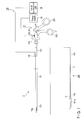
- FIG. 1 Referring to FIG. 1 , FIG. 2 , FIG. 3, FIG. 4 , FIG. 5 , FIG. 6 , FIG. 7 , and FIG. 8 , a first embodiment will be described. In some of the drawings, some members are not shown for clarification of the drawings.
- a treatment system 100 comprises a treatment instrument 1, a power supply 33, and a liquid conveyance unit 35.
- the treatment instrument 1 as shown in FIG. 1 is, for example, a bipolar electrical treatment instrument for use in surgical operations, which is a high-frequency electrosurgical treatment instrument for operations.
- the surgical operations mainly include liver resection, kidney resection, and pancreas resection under a laparoscope.
- the treatment instrument 1 is used, for example, for stripping, gripping, resection, and sampling of living tissue, and electrocoagulation and astriction for bleeding.
- the main applications that is, in resection of parenchymal organs such as the liver, kidneys, and pancreas, oozing bleeding is likely to occur, in which the resected surface bleeds uniformly.
- Electrocoagulation with supply of liquid is effective for such bleeding. This allows the bleeding resected surface to be coagulated uniformly. Moreover, excessive coagulation is prevented and heat damage to living tissue is minimized because the living tissue is heated to temperatures not higher than the boiling point of the liquid.
- the treatment instrument 1 comprises a forceps unit 300 including a pair of forceps pieces 151a, 151b and a manipulation rod member 11, and a shaft member 13 into which the manipulation rod member 11 is inserted so that the shaft member 13 covers (externally covers) the manipulation rod member 11 so as to wrap the manipulation rod member 11 from a distal end portion 11a of the manipulation rod member 11 to a proximal end portion 11b of the manipulation rod member 11 and is inserted into the body cavity together with the manipulation rod member 11.
- the treatment instrument 1 further comprises a manipulation portion 31 including a movable handle 201 removably coupled to the proximal end portion 11b of the manipulation rod member 11 and a fixed handle 202 removably coupled to a proximal end portion 13b of the shaft member 13, the movable handle 201 is opened/closed relative to the fixed handle 202 thereby opening/closing the forceps pieces 151a, 151b.
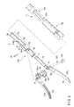
- the forceps unit 300 includes the pair of forceps pieces 151a, 151b, an insulating member 55, a transmission member 51, the elongated manipulation rod member 11 having a sheath member 11d, an insulating tubular member 53, a distal end cover member 12, a fulcrum pin member 501, an action pin member 15d, and an action pin member 502.
- the pair of forceps pieces 151a, 151b have grip surfaces 17a, 17b opposed to each other to grip an affected area.
- the forceps pieces 151a, 151b are capable of being opened/closed relative to each other.
- the grip surfaces 17a, 17b have projections and depressions so as to facilitate gripping of an affected area.
- the forceps pieces 151a, 151b are a pair of bipolar electrodes.
- the insulating member 55 is disposed at the proximal end portions of the forceps pieces 151a, 151b and insulates one forceps piece 151a from the other forceps piece 151b.
- the insulating member 55 is fitted in a proximal end opening portion 152a provided at the proximal end portion of the forceps piece 151a.
- the insulating member 55 is pivotably coupled together with the forceps piece 151a to a proximal end portion 15b of the forceps piece 151b via the action pin member 15d. That is, the action pin member 15d couples the insulating member 55, the forceps piece 151a, and the forceps piece 151b together.
- the insulating member 55 has an opening portion 55f. The proximal end portion of the opening portion 55f is fitted in part of the proximal end portion 15b of the forceps piece 151b.
- the transmission member 51 couples with one of the forceps piece 151a and the forceps piece 151b such that the forceps piece 151a and the forceps piece 151b are pivotably coupled with each other.
- the transmission member 51 is coupled with the proximal end portion 15b of the forceps piece 151b, for example, via the action pin member 502.
- the manipulation rod member 11 has the distal end portion 11a and the proximal end portion 11b. As shown in FIG. 8 and FIG. 9 , the distal end portion 11a is fixed to the transmission member 51.
- the transmission member 51 and the manipulation rod member 11 are fixed by screw fastening, brazing, thermal fitting, or any other means.
- the manipulation rod member 11 is, for example, a metal cylindrical member. As shown in FIG. 3 and FIG. 4 , the manipulation rod member 11 has the sheath member 11d that sheathes the manipulation rod member 11.
- the sheath member 11d is an insulating member that insulates the manipulation rod member 11. Such a sheath member 11d functions as an insulating coating such as PTFE.
- the distal end cover member 12 has a bifurcated distal end portion 12a, a large diameter portion 12b having the shape of a hollow cylinder, and a small diameter portion 12c.
- the small diameter portion 12c is disposed at the proximal end portion of the distal end cover member 12.
- the large diameter portion 12b is sandwiched between the distal end portion 12a and the small diameter portion 12c in the axial direction of the distal end cover member 12.
- the distal end portion 12a is integral with the large diameter portion 12b, and the large diameter portion 12b is integral with the small diameter portion 12c.
- the small diameter portion 12c has projection portions 12e disposed at the proximal end portion of the small diameter portion 12c.
- the projection portions 12e are removably engaged with engagement cuts 313 of the shaft member 13 described later, whereby the shaft member 13 and the distal end cover member 12 are removably fixed.
- the distal end portion 12a accommodates the proximal end opening portion 152a of the forceps piece 151a, the insulating member 55, and the proximal end portion 15b of the forceps piece 151b.
- the distal end portion 12a has the fulcrum pin member 501 that functions as the fulcrum of pivot.
- the distal end portion 12a is coupled with the forceps piece 151a and the insulating member 55 via the fulcrum pin member 501, for example, such that the forceps piece 151a and the insulating member 55 pivot relative to the distal end portion 12a with the fulcrum pin member 501 as a fulcrum.
- the distal end cover member 12 has the fulcrum pin member 501 that functions as a fulcrum for pivotably coupling, for example, the forceps piece 151a to the distal end portion 12a.
- the insulating tubular member 53 having the shape of a hollow cylinder is fixed in the interior of the large diameter portion 12b of the distal end cover member 12.
- the large diameter portion 12b can accommodate the insulating tubular member 53, and the accommodating large diameter portion 12b can be removably fixed to the insulating tubular member 53.
- the fixing is thermal fitting or adhesion, or both.
- the inner diameter of the insulating tubular member 53 and the inner diameter of the small diameter portion 12c have such a size that allows insertion and removal of the transmission member 51 and the manipulation rod member 11.
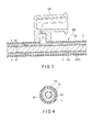
- the shaft member 13 has a cylindrical shape such that the manipulation rod member 11 is inserted into the shaft member 13 and that the shaft member 13 covers the manipulation rod member 11.
- the inner diameter of the shaft member 13 is larger than the outer diameter of the manipulation rod member 11 including the sheath member 11d. Accordingly, when the manipulation rod member 11 is inserted into the shaft member 13, a flow channel portion 43 functioning as a space portion is formed between the manipulation rod member 11 and the shaft member 13 in the radial direction of the shaft member 13.
- This flow channel portion 43 represents the space portion between the exterior of the manipulation rod member 11 and the interior of the shaft member 13, in other words, between the outer peripheral surface of the manipulation rod member 11 (the sheath member 11d) and the inner peripheral surface of the shaft member 13.
- the flow channel portion 43 is also covered with the shaft member 13.
- the flow channel portion 43 is disposed along the longitudinal direction of the shaft member 13 (the manipulation rod member 11).
- Such a flow channel portion 43 is included in a flow channel portion (liquid conveyance portion) 41 through which liquid flows, for example, from the proximal end portion 11b side toward the distal end portion 11a side of the manipulation rod member 11 by means of the liquid conveyance unit 35.
- liquid flows from the proximal end portion side toward the distal end portion side of the flow channel portion 43.
- the flow channel portion 43 is formed between the manipulation rod member 11 and the shaft member 13 in the radial direction of the shaft member 13 and is disposed along the longitudinal direction of the manipulation rod member 11 when the manipulation rod member 11 is inserted into the shaft member 13.
- liquid flows from the proximal end portion side of the flow channel portion 43 toward the distal end portion side of the flow channel portion 43.
- the shaft member 13 contains, for example, a metal such as SUS. Such a shaft member 13 has a sheath member 13d that sheathes the shaft member 13, as shown in FIG. 3 and FIG. 4 .
- the sheath member 13d has an insulating material that insulates the shaft member 13.
- Such a sheath member 13d has an insulating coating such as PTFE.
- the shaft member 13 has an inlet port portion 13f that is disposed on the proximal end portion 13b side of the shaft member 13 and through which liquid from the liquid conveyance unit 35 outside the treatment instrument 1 is fed to the flow channel portion 43.
- the inlet port portion 13f is a supply port that is coupled with the liquid conveyance unit 35 and through which liquid from the liquid conveyance unit 35 is supplied to the flow channel portion 43.
- the inlet port portion 13f passes through the shaft member 13 and the sheath member 13d and communicates with the flow channel portion 43 (the interior of the shaft member 13).
- the liquid supplied from the liquid conveyance unit 35 flows into the flow channel portion 43 through the inlet port portion 13f and is conveyed through from the flow channel portion 43 toward the distal end cover member 12.
- the shaft member 13 has a groove cover member 13g that covers groove portions 45 described later so as to cap the groove portions 45 when the manipulation rod member 11 is inserted into the shaft member 13.
- the groove cover member 13g is formed as a cylindrical member into which a distal end portion 13a of the shaft member 13 and the distal end cover member 12 are inserted. As described above, the groove cover member 13g is disposed at the distal end portion 13a side of the shaft member 13. Such a groove cover member 13g is included in the shaft member 13. The distal end portion of the groove cover member 13g is exposed, and the proximal end portion of the groove cover member 13g is covered by the sheath member 13d.
- the proximal end portion of the groove cover member 13g covers the engagement cuts 313 and proximal end portions 45b of the groove portions 45.
- the distal end portion of the groove cover member 13g is bifurcated into two.
- the distal end portions of the groove cover member 13g are disposed so as to correspond to the arrangement position of distal end portions 45a of the groove portions 45.
- the distal end portions of the groove cover member 13g are therefore disposed 180° apart from each other in the circumferential direction in the longitudinal direction of the shaft member 13 (the manipulation rod member 11).
- the distal end portions of the groove cover member 13g cover the distal end portions 45a of the groove portions 45.
- the groove cover member 13g may be separated from the distal end portion 13a as mentioned above or may be integral with the distal end portion 13a. In the case where the groove cover member 13g is integral with the distal end portion 13a, the groove cover member 13g is part of the bifurcated distal end portion 13a.
- the shaft member 13 has two engagement cuts 313 substantially in the shape of a L that are disposed at the distal end portion 13a of the shaft member 13.
- the engagement cuts 313 are provided axially symmetric with each other.
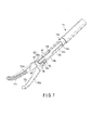
- FIG. 7 shows the distal end portion of the treatment instrument 1 without showing the sheath member 13d and the groove cover member 13g.
- the projection portions 12e enter the engagement cuts 313, and the projection portions 12e are engaged with the proximal end portions of the engagement cuts 313, whereby the distal end cover member 12 is fixed to the shaft member 13.
- the shaft member 13 including the engagement cuts 313 contains a metal such as SUS as described above. Accordingly, the shaft member 13 is engaged with the distal end cover member 12 of a metal such as SUS so that electrical continuity is established between the shaft member 13 and the distal end cover member 12.
- the manipulation rod member 11 When the movable handle 201 is closed relative to the fixed handle 202, the manipulation rod member 11 is pulled toward the manipulation portion 31, and the forceps pieces 151a, 151b are closed. Conversely, when the movable handle is opened relative to the fixed handle, the manipulation rod member 11 is pushed toward the forceps pieces 151a, 151b, and the forceps pieces 151a, 151b are opened.
- the treatment instrument 1 in the present embodiment is a bipolar high-frequency electrical treatment instrument.
- the forceps pieces 151a, 151b, the distal end cover member 12, the manipulation rod member 11, the transmission member 51, and the shaft member 13 including the engagement cuts 313 contain a metal such as SUS.
- the insulating tubular member 53 fitted on the inner surface of the large diameter portion 12b, the sheath member 11d that sheathes the manipulation rod member 11 and the transmission member 51, the insulating member 55, the action pin member 15d, and the action pin member 502 are formed of, for example, an insulating material such as PFA, PTFE, alumina, aluminium nitride, or zirconia.
- the manipulation portion 31 has a connector portion 31a to be connected to the power supply 33.
- the connector portion 31a has an active electrode 31b and a return electrode 31c.
- the active electrode 31b is in electrical conduction with the manipulation rod member 11, the transmission member 51, and the forceps piece 151b.
- the return electrode 31c is in electrical conduction with the shaft member 13, the distal end cover member 12, and the forceps piece 151a.
- the conducting path of the active electrode 31b from the manipulation rod member 11 to the forceps piece 151b through the transmission member 51 and the conducting path of the return electrode 31c from the forceps piece 151a to the shaft member 13 through the distal end cover member 12 are electrically insulated by the sheath member 11d, the insulating tubular member 53, the insulating member 55, the action pin member 15d, and the action pin member 502.
- the power supply 33 is electrically connected with the connector portion 31a to supply power to the forceps pieces 151a, 151b.
- the liquid conveyance unit 35 is coupled to the inlet port portion 13f to convey liquid from the inlet port portion 13f to the flow channel portion 43 and supply the liquid from the opening portion 55f of the insulating member 55 toward an affected area.
- An example of the liquid in the liquid conveyance unit 35 is an isotonic solution having the same osmotic pressure as living tissue in human bodies.
- An example of the isotonic solution is physiological saline solution.
- the flow channel portion 41 includes the inlet port portion 13f described above, the flow channel portion 43 described above, the engagement cuts 313 of the shaft member 13, the groove portions 45 in communication with the engagement cuts 313 at the proximal end portions 45b of the groove portions 45, through hole portions 47 in communication with the groove portions 45, through hole portions 55d in communication with the through hole portions 47, and the opening portion 55f described above in communication with the through hole portions 55d.
- the flow channel portion 43 is formed between the manipulation rod member 11 and the shaft member 13 in the radial direction and is disposed along the longitudinal direction of the shaft member 13 (the manipulation rod member 11).
- the groove portion 45 communicates with the flow channel portion 43 and is disposed along the longitudinal direction of the manipulation rod member 11 on an outer peripheral surface 12d of the distal end cover member 12. Liquid flows into the groove portion 45 from the flow channel portion 43.
- the groove portions 45 are disposed at both of the two bifurcated distal end portions 12a of the distal end cover member 12.
- the groove portion 45 is disposed from the through hole portion 47 provided at the bifurcated distal end portion 12a of the distal end cover member 12 to the large diameter portion 12b, along the longitudinal direction of the shaft member 13 (the manipulation rod member 11).
- the distal end portion 45a of the groove portion 45 is formed in such a manner that the distal end cover member 12 is partially depressed.
- the distal end portion 45a functions as the flow channel portion 41.
- the proximal end portion 45b of the groove portion 45 is disposed at the large diameter portion 12b so as to pass through the large diameter portion 12 in the thickness direction of the large diameter portion 12. That is, the proximal end portion 45b functions as a through hole portion. As shown in FIG.
- the outer peripheral surface of the insulating tubular member 53 inserted into the large diameter portion 12b functions as the bottom surface of the proximal end portion 45b.
- the proximal end portion 45b and the outer peripheral surface of the insulating tubular member 53 function as the flow channel portion 41.
- Such two groove portions 45 are disposed symmetrically with respect to the center axis of the manipulation rod member 11.
- the groove portion 45 is disposed, for example, orthogonally to the forceps pieces 151a, 151b.
- the groove portion 45 is therefore disposed, for example, orthogonally to the opening/closing direction of the forceps pieces 151a, 151b. As shown in FIG.
- the opening direction of the groove portion 45 on the proximal end portion 45b side generally agrees with the opening direction of the engagement cut 313 of the shaft member 13.
- the groove portion 45 is covered (capped) with the groove cover member 13g.
- the distal end portion 45a of the groove portion 45 communicates with the through hole portion 47.
- the through hole portion 47 is disposed at the proximal end portion of the forceps piece 151a so as to pass through the proximal end portion of the forceps piece 151a.
- the liquid flows into the through hole portion 47 from the groove portion 45.
- the through hole portion 47 communicates with the proximal end opening portion 152a.
- the through hole portion 47 is inclined relative to the longitudinal direction of the shaft member 13 (the manipulation rod member 11).
- the through hole portion 47 passes through the proximal end portion 15b at an inclination so as to extend from the outer peripheral surface 12d of the distal end cover member 12 toward the center axis of the manipulation rod member 11, that is, so as to be disposed from the exterior to the interior of the manipulation rod member 11.
- the forceps piece 151a has the through hole portion 47 that is disposed at the proximal end portion of the forceps piece 151a, communicates with the distal end portion 45a of the groove portion 45, and is inclined relative to the longitudinal direction of the shaft member 13 (the manipulation rod member 11) so as to extend from the outer peripheral surface 12d of the distal end cover member 12 toward the center axis of the manipulation rod member 11.
- the through hole portion 47 communicates with the through hole portion 55d that is disposed in the insulating member 55 and communicates with the opening portion 55f.
- the liquid flows into the through hole portion 55d from the groove portion 45 through the through hole portion 47.
- the through hole portion 55d is inclined in the same manner as the through hole portion 47.
- the opening portion 55f is disposed at a distal end portion 55a of the insulating member 55.
- the opening portion 55f communicates with the through hole portion 55d and is disposed in the insulating member 55 along the longitudinal direction of the insulating member 55.
- the liquid flows into the opening portion 55f from the through hole portion 55d.
- the opening portion 55f then supplies the liquid near the proximal end portions of the forceps pieces 151a, 151b.
- the insulating member 55 has the through hole portion 55d that communicates with the through hole portion 47 and is inclined in the same manner as the through hole portion 47, and the opening portion 55f that communicates with the through hole portion 55d and is disposed along the longitudinal direction of the insulating member 55.
- the manipulation rod member 11 is inserted into (put into) the shaft member 13 so that the flow channel portion 43 is formed as shown in FIG. 3 and FIG. 4 .
- the groove cover member 13g covers the groove portion 45.
- the manipulation portion 31 is coupled to the proximal end portion 11b of the manipulation rod member 11 and the proximal end portion 13b of the shaft member 13. The treatment instrument 1 is then inserted into the body cavity.
- the inlet port portion 13f is coupled with the liquid conveyance unit 35. Liquid thus flows from the liquid conveyance unit 35 to the flow channel portion 43 through the inlet port portion 13f. The liquid flowing into the flow channel portion 43 flows into the groove portion formed with the engagement cut 313 of the shaft member 13 and the small diameter portion 12c of the distal end cover member 12. As shown in FIG. 8 , the liquid then flows from the engagement cut 313 in this groove portion into the opening portion 55f through the groove portion 45, the through hole portion 47, and the through hole portion 55d. The liquid further flows out of the opening portion 55f toward an affected area.
- the liquid flows into the opening portion 55f from the inlet port portion 13f without leaking to the outside of the treatment instrument 1.
- the forceps pieces 151a, 151b come into contact with the affected area where blood oozes, for example, the resected surface of the liver parenchyma, and the liquid flows onto the resected surface from the opening portion 55f.
- High-frequency power is then supplied from the power supply 33 to the forceps pieces 151a, 151b.
- the liquid flowing out of the opening portion 55f near the forceps pieces 151a, 151b is boiled by high-frequency power to coagulate the affected area and stop the bleeding.
- the affected area is not excessively heated because the boiling point of the liquid such as physiological saline solution is about 100°C.
- the treatment instrument 1 stops bleeding efficiently and widely when compared with a treatment instrument that treats an affected area only by high-frequency power without using a liquid, because the affected area soaked in the boiled liquid is coagulated uniformly. Since the treatment instrument 1 is bipolar, heat damage to the affected area in the depth direction is not as large as that of the monopolar type, and the affected area is treated easily and more gently.
- the liquid flows out of the opening portion 55f and washes the affected area, thereby allowing identification of the bleeding point.
- the movable handle 201 of the manipulation portion 31 is thereafter closed, so that the forceps pieces 151a, 151b pinch tissue near the bleeding point.
- the forceps pieces 151a, 151b are supplied with high-frequency power from the power supply 33 to coagulate tissue by high-frequency power while pressing the tissue near the bleeding point.
- the forceps pieces 151a, 151b provide high-frequency energy to the bleeding point supplied with the liquid from the opening portion 55f, while pinching and pressing the bleeding point where blood spurts from. The oozing bleeding and the spurting bleeding are thus stopped simultaneously.
- the treatment instrument 1 is a bipolar high-frequency electrical treatment instrument which can reduce an invasion and can treat an affected area easily and gently.
- liquid can be conveyed to an affected area through the flow channel portion 43, the groove portion 45, the through hole portions 47, 55d, and the opening portion 55f.
- the forceps pieces 151a, 151b are high-frequency energized in this state, whereby the affected area can be thermally coagulated with the boiled liquid, and bleeding in a wide range can be stopped quickly and efficiently while preventing excessive heat damage to the affected area.
- the liquid fills up between the forceps pieces 151a, 151b and living tissue in the affected area, thereby preventing adhesion of the living tissue to the forceps pieces 151a, 151b.
- the affected area can be treated easily by conveying liquid to the affected area.
- the forceps pieces 151a, 151b can be opened/closed through manipulation of the manipulation portion 31 to allow stripping, gripping, resection, and sampling of living tissue as well as pressing of the bleeding point.
- the flow channel portion 43 and the groove portion 45 are formed.
- the flow channel portion 43 and the groove portion 45 are formed as part of the flow channel portion 41 that conveys a liquid, thereby eliminating the need for disposing a tubular member such as a tube serving as the flow channel portion 41 in the interior of the shaft member 13. Accordingly, in the present embodiment, the diameter of the shaft member 13 can be reduced.
- the flow channel portion 43 is covered with the shaft member 13, and the groove portion 45 is covered with the groove cover member 13g, thereby preventing liquid from leaking to the outside of the treatment instrument 1.
- the liquid thus can be fed from the inlet port portion 13f to the opening portion 55f without leakage.
- the inlet port portion 13f enables a clean liquid to constantly flow toward the affected area.
- two sets of the groove portion 45 and the through hole portions 47, 55d are provided symmetrically with respect to the center axis of the manipulation rod member 11 to allow liquid to be conveyed stably to the affected area without depending on the orientation of the forceps pieces 151a, 151b.
- FIG. 9 a second embodiment will be described.
- the same parts as in the foregoing first embodiment are denoted with the same reference signs and a detailed description thereof will be omitted. Some parts are omitted in the drawings for the sake of simplification.
- through hole portions 47, 55d in the present embodiment have the shape of a long hole portion so as to always communicate with a groove portion 45 without being affected by the opening/closing of forceps pieces 151a, 151b.
- the through hole portions 47, 55d are arranged with the same width on a circumferential line 501a around a fulcrum pin member 501.
- the groove portion 45 and the through hole portions 47, 55d are always in communication, and a breakage in communication is prevented. As described above, the communication between the groove portion 45 and the through hole portions 47, 55d is always maintained.
- the through hole portions 47, 55d can always be opened without being affected by the open/closed angle of the forceps pieces 151a, 151b, so that liquid can easily flow from the groove portion 45 toward the through hole portions 47, 55d.
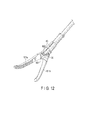
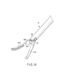
- FIG. 12 and FIG. 13 a third embodiment will be described.
- the same parts as in the foregoing first embodiment are denoted with the same reference signs and a detailed description thereof will be omitted. Some parts are omitted in the drawings for the sake of simplification.
- a flow channel portion 41 of a distal end cover member 12 is formed with a groove portion 45 alone.
- the insulating member 55 has a flat portion 601 disposed at the distal end portion of the insulating member 55.
- the forceps pieces 151a, 151b are always located below the proximal end portion of a shaft member 13. For this reason, liquid can be supplied near the forceps pieces 151a, 151b with the groove portion 45 alone.
- a groove cover member 13g can be eliminated as long as the angle of the shaft member 13 relative to the horizontal surface is inclined at about 30 degrees or more.
- the present embodiment can provide a low-cost bipolar electrical treatment instrument for use in a body cavity, which can coagulate an affected area by high frequency power while supplying liquid to the affected area.
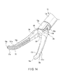
- At least one of a grip surface 17a of one forceps piece 151a and a grip surface 17b of the other forceps piece 151b may have a grip groove portion 15f that communicates with an opening portion 55f and is disposed along the longitudinal direction of the forceps pieces 151a, 151b to allow a fluid to flow from a proximal end portion 15b to a distal end portion 15a of the forceps pieces 151a, 151b.
- the liquid can be fed to the distal end portion 15a of the forceps pieces 151a, 151b thereby preventing adhesion of living tissue in the affected area to the grip surfaces 17a, 17b.
- Provision of a plurality of grip groove portions 15f can achieve the same advantageous effects.
- a pair of forceps pieces 151a, 151b have insulating grip members 153a, 153b having grip surfaces 17a, 17b.
- the insulating grip members 153a, 153b are disposed along the longitudinal direction of the forceps pieces 151a, 151b.
- the insulating grip members 153a, 153b insulate high-frequency current from the liquid flowing from an opening portion 55f to the grip surfaces 17a, 17b.
- the insulating grip members 153a, 153b are formed of an insulating material, for example, such as a ceramic and a resin.
- the ceramic includes, for example, alumina and zirconia having a dielectric constant of 10 or less.
- the resin includes, for example, polyetheretherketone having a dielectric constant of around 2.
- the liquid is physiological saline solution
- the impedance of a high-frequency region relative to physiological saline solution becomes lower than the desired value
- the output of high-frequency power decreases, and the resulting treatment time is likely to increase. It is therefore necessary to prevent a reduction in impedance.
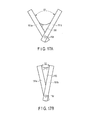
- the opening angle be ⁇ 1 in a case where the opening angle between the forceps pieces 151a and 151b is large as shown in FIG. 17A , for example, in a state in which the forceps pieces 151a and 151b are opened to the maximum.
- the opening angle be ⁇ 2 in a case where the opening angle between the forceps pieces 151a and 151b is small as shown in FIG. 17B , for example, in a state in which the grip surfaces of the forceps pieces 151a, 151b are entirely wet with liquid 150.
- the relationship between ⁇ 1 and ⁇ 2 is ⁇ 1 > ⁇ 2.
- the wet area of the forceps pieces 151a, 151b is affected by the opening angle between the forceps pieces 151a and 151b.
- the wet area increases as the opening angle decreases.
- the liquid 150 such as physiological saline solution has a high electrical conductivity in a high-frequency region. This means that, in general, the wet area increases as the impedance decreases. That is, the treatment time may vary with the wet area (the opening angle) of the forceps pieces 151a, 151b.
- the forceps pieces 151a, 151b have the insulating grip members 153a, 153b as shown in FIG. 17C and FIG. 17D .
- the insulating grip members 153a, 153b prevent reduction in impedance even when the opening angle is small.
- the length of the insulating grip members 153a, 153b will be described briefly below.
- the length of the forceps piece 151a is L.
- the length of the forceps piece 151a represents a position from the distal end portion of the forceps piece 151a to an action pin member 15d.
- the insulating grip members 153a, 153b are disposed from the distal end portions of the forceps pieces 151a, 151b to the desired position in the forceps pieces 151a, 151b.
- the desired position represents the proximal end portion side of the forceps pieces 151a, 151b (the side closer to the action pin member 15d that functions as the opening/closing shaft).
- the desired position represents, for example, a position in contact with the liquid 150 when the forceps pieces 151a, 151b are opened to the maximum.
- the length of the insulating grip members 153a, 153b (the length from the distal end portions of the forceps pieces 151a, 151b to the desired position) be L1.
- the length L1 of the insulating grip members 153a, 153b represents a position where the insulating grip members 153a, 153b can come into contact with the liquid 150 when the opening angle is ⁇ 1.
- the length L1 of the insulating grip members 153a, 153b therefore is at least a length equal to or greater than L ⁇ (1 - (sin ⁇ 1/sin ⁇ 2) 1/2 ).
- a part in the forceps pieces 151a, 151b that is always wet with the liquid 150 without being affected by the opening angle is a wet part 154.
- the wet part 154 represents, for example, the forceps pieces 151a, 151b between the insulating grip members 153a, 153b and the action pin member 15d.
- the wet area of the wet part 154 is substantially constant without being affected by the opening angle between the forceps pieces 151a and 151b.
- the area of the wet part 154 of the forceps pieces 151a, 151b does not vary even when the opening angle between the forceps pieces 151a and 151b changes.
- the provision of the insulating grip members 153a, 153b having such a length can prevent reduction in impedance.
- the provision of the insulating grip members 153a, 153b allows the wet area to be substantially constant and prevents reduction in impedance even when the opening angle is small. Accordingly, the present modification can prevent reduction in output of high-frequency power and prevent increase in treatment time. That is, the present modification can reliably prevent the treatment time from varying in accordance with the opening angle (the wet area) between the forceps pieces 151a and 151b.
- the insulating grip members 153a, 153b are disposed from the distal end portions of the forceps pieces 151a, 151b to the desired position in the forceps pieces 151a, 151b, thereby reliably preventing reduction in output of high-frequency power and preventing increase in the treatment time.
- the insulating grip members 153a, 153b may be removable from the forceps pieces 151a, 151b as shown in FIG. 18 .
- the insulating grip members 153a, 153b each have a protrusion 155a
- the forceps pieces 151a, 151b each have a recession 155b in which the protrusion 155a removably slides.
- the insulating grip members 153a, 153b can be used, or the forceps pieces 151a, 151b can be directly used by removing the insulating grip members 153a, 153b.
- metal members having the same shape as the insulating grip members 153a, 153b and having the grip surfaces 17a, 17b and the protrusion 155a may be disposed at the forceps pieces 151a, 151b with the recession 155b interposed.
- At least one of a forceps piece 151a and the other forceps piece 151b has an open window portion 156.
- the open window portion 156 is disposed in the forceps piece 151a so as to pass through the forceps piece 151a including a grip surface 17a in the thickness direction of the forceps piece 151a.
- the forceps piece 151b has the same structure.
- liquid supplied from an opening portion 55f is accumulated in the open window portion 156, thereby preventing the high-frequency-heated liquid from unnecessarily flowing out of the vicinity of the forceps piece 151a and the forceps piece 151b.
Landscapes
- Health & Medical Sciences (AREA)
- Surgery (AREA)
- Engineering & Computer Science (AREA)
- Life Sciences & Earth Sciences (AREA)
- Biomedical Technology (AREA)
- Otolaryngology (AREA)
- Nuclear Medicine, Radiotherapy & Molecular Imaging (AREA)
- Plasma & Fusion (AREA)
- Physics & Mathematics (AREA)
- Heart & Thoracic Surgery (AREA)
- Medical Informatics (AREA)
- Molecular Biology (AREA)
- Animal Behavior & Ethology (AREA)
- General Health & Medical Sciences (AREA)
- Public Health (AREA)
- Veterinary Medicine (AREA)
- Surgical Instruments (AREA)
Applications Claiming Priority (2)
| Application Number | Priority Date | Filing Date | Title |
|---|---|---|---|
| US201361750942P | 2013-01-10 | 2013-01-10 | |
| PCT/JP2013/083650 WO2014109181A1 (ja) | 2013-01-10 | 2013-12-16 | 手術用高周波電気外科用処置具と手術用高周波電気外科用システム |
Publications (3)
| Publication Number | Publication Date |
|---|---|
| EP2944280A1 true EP2944280A1 (de) | 2015-11-18 |
| EP2944280A4 EP2944280A4 (de) | 2016-09-07 |
| EP2944280B1 EP2944280B1 (de) | 2025-02-12 |
Family
ID=51166841
Family Applications (1)
| Application Number | Title | Priority Date | Filing Date |
|---|---|---|---|
| EP13870674.2A Active EP2944280B1 (de) | 2013-01-10 | 2013-12-16 | Elektrochirurgisches hochfrequenzinstrument für operationen und elektrochirurgisches hochfrequenzsystem für operationen |
Country Status (5)
| Country | Link |
|---|---|
| US (1) | US10912600B2 (de) |
| EP (1) | EP2944280B1 (de) |
| JP (1) | JP5677633B2 (de) |
| CN (1) | CN104144654B (de) |
| WO (1) | WO2014109181A1 (de) |
Cited By (2)
| Publication number | Priority date | Publication date | Assignee | Title |
|---|---|---|---|---|
| US10973540B2 (en) | 2016-02-02 | 2021-04-13 | Olympus Corporation | Endoscopic surgical device |
| US11207088B2 (en) | 2016-02-02 | 2021-12-28 | Olympus Corporation | Endoscopic surgical device |
Families Citing this family (18)
| Publication number | Priority date | Publication date | Assignee | Title |
|---|---|---|---|---|
| GB2480498A (en) | 2010-05-21 | 2011-11-23 | Ethicon Endo Surgery Inc | Medical device comprising RF circuitry |
| US10959771B2 (en) * | 2015-10-16 | 2021-03-30 | Ethicon Llc | Suction and irrigation sealing grasper |
| US10987156B2 (en) | 2016-04-29 | 2021-04-27 | Ethicon Llc | Electrosurgical instrument with electrically conductive gap setting member and electrically insulative tissue engaging members |
| CN109152602B (zh) * | 2016-05-25 | 2021-02-12 | 奥林巴斯株式会社 | 送液器具、处置器具单元和处置系统 |
| US10751117B2 (en) | 2016-09-23 | 2020-08-25 | Ethicon Llc | Electrosurgical instrument with fluid diverter |
| US11033325B2 (en) | 2017-02-16 | 2021-06-15 | Cilag Gmbh International | Electrosurgical instrument with telescoping suction port and debris cleaner |
| US10799284B2 (en) | 2017-03-15 | 2020-10-13 | Ethicon Llc | Electrosurgical instrument with textured jaws |
| US11497546B2 (en) | 2017-03-31 | 2022-11-15 | Cilag Gmbh International | Area ratios of patterned coatings on RF electrodes to reduce sticking |
| WO2019028647A1 (en) * | 2017-08-08 | 2019-02-14 | Covidien Lp | ELECTROSURGICAL APPARATUS WITH SAFETY INSULATION CHARACTERISTICS |
| US11490951B2 (en) | 2017-09-29 | 2022-11-08 | Cilag Gmbh International | Saline contact with electrodes |
| US11484358B2 (en) | 2017-09-29 | 2022-11-01 | Cilag Gmbh International | Flexible electrosurgical instrument |
| US11033323B2 (en) | 2017-09-29 | 2021-06-15 | Cilag Gmbh International | Systems and methods for managing fluid and suction in electrosurgical systems |
| JP6815610B1 (ja) * | 2019-08-08 | 2021-01-20 | リバーフィールド株式会社 | 高周波鉗子 |
| JP7491720B2 (ja) * | 2020-04-10 | 2024-05-28 | 清明 本間 | 内視鏡用処置具 |
| CN112315577A (zh) * | 2020-11-04 | 2021-02-05 | 安瑞医疗器械(杭州)有限公司 | 一种带旋转的头部绝缘结构 |
| US12471982B2 (en) | 2020-12-02 | 2025-11-18 | Cilag Gmbh International | Method for tissue treatment by surgical instrument |
| US12508021B2 (en) | 2021-11-01 | 2025-12-30 | Cilag Gmbh International | Devices, systems, and methods for detecting tissue and foreign objects during a surgical operation |
| US11957342B2 (en) | 2021-11-01 | 2024-04-16 | Cilag Gmbh International | Devices, systems, and methods for detecting tissue and foreign objects during a surgical operation |
Family Cites Families (22)
| Publication number | Priority date | Publication date | Assignee | Title |
|---|---|---|---|---|
| JPS6036041A (ja) | 1983-08-09 | 1985-02-25 | 太田 富雄 | 手術に用いる双極電気凝固用ピンセット |
| US5190541A (en) * | 1990-10-17 | 1993-03-02 | Boston Scientific Corporation | Surgical instrument and method |
| JP3344780B2 (ja) * | 1993-08-05 | 2002-11-18 | オリンパス光学工業株式会社 | 処置具システム |
| US5456684A (en) * | 1994-09-08 | 1995-10-10 | Hutchinson Technology Incorporated | Multifunctional minimally invasive surgical instrument |
| US5891142A (en) * | 1996-12-06 | 1999-04-06 | Eggers & Associates, Inc. | Electrosurgical forceps |
| US6953461B2 (en) * | 2002-05-16 | 2005-10-11 | Tissuelink Medical, Inc. | Fluid-assisted medical devices, systems and methods |
| US7101371B2 (en) * | 2001-04-06 | 2006-09-05 | Dycus Sean T | Vessel sealer and divider |
| EP2275050A1 (de) | 2001-09-05 | 2011-01-19 | Salient Surgical Technologies, Inc. | Flüssigkeitsgestützte elektrochirurgische Vorrichtungen, Verfahren und Systeme |
| EP1435865A4 (de) * | 2001-09-05 | 2007-03-14 | Tissuelink Medical Inc | Flüssigkeitsgestützte medizinprodukte, flüssigkeitsabgabesysteme und regler für diese produkte, und vefahren |
| JP4131014B2 (ja) * | 2003-03-18 | 2008-08-13 | Hoya株式会社 | 内視鏡用嘴状処置具 |
| JP4624692B2 (ja) | 2004-02-13 | 2011-02-02 | オリンパス株式会社 | 内視鏡用処置具 |
| JP4714520B2 (ja) | 2005-07-20 | 2011-06-29 | Hoya株式会社 | 送水機能を有する内視鏡用高周波処置具 |
| CN101227864A (zh) * | 2005-08-11 | 2008-07-23 | 奥林巴斯株式会社 | 内窥镜用处理器具 |
| US8298232B2 (en) * | 2006-01-24 | 2012-10-30 | Tyco Healthcare Group Lp | Endoscopic vessel sealer and divider for large tissue structures |
| US20080119846A1 (en) * | 2006-10-11 | 2008-05-22 | Rioux Robert F | Methods and apparatus for percutaneous patient access and subcutaneous tissue tunneling |
| US7935114B2 (en) * | 2007-02-14 | 2011-05-03 | Olympus Medical Systems Corp. | Curative treatment system, curative treatment device, and treatment method for living tissue using energy |
| US20100069903A1 (en) * | 2008-09-18 | 2010-03-18 | Tyco Healthcare Group Lp | Vessel Sealing Instrument With Cutting Mechanism |
| US20100185196A1 (en) * | 2009-01-21 | 2010-07-22 | Satomi Sakao | Medical treatment apparatus, treatment instrument and treatment method for living tissue using energy |
| US20100185197A1 (en) * | 2009-01-21 | 2010-07-22 | Satomi Sakao | Medical treatment apparatus, treatment instrument and treatment method for living tissue using energy |
| EP2471472B1 (de) * | 2010-03-11 | 2014-10-29 | Olympus Medical Systems Corp. | Zange zur unterstützung intraperitonealer eingriffe und entsprechende verwendungsmethode |
| CN201949097U (zh) * | 2011-02-28 | 2011-08-31 | 桐庐洲济医疗器械有限公司 | 直视钝头抓紧钳 |
| WO2012124653A1 (ja) * | 2011-03-17 | 2012-09-20 | オリンパスメディカルシステムズ株式会社 | 医療用送液装置及び医療用処置装置 |
-
2013
- 2013-12-16 JP JP2014527421A patent/JP5677633B2/ja active Active
- 2013-12-16 WO PCT/JP2013/083650 patent/WO2014109181A1/ja not_active Ceased
- 2013-12-16 EP EP13870674.2A patent/EP2944280B1/de active Active
- 2013-12-16 CN CN201380011809.8A patent/CN104144654B/zh active Active
-
2014
- 2014-07-23 US US14/339,009 patent/US10912600B2/en active Active
Cited By (3)
| Publication number | Priority date | Publication date | Assignee | Title |
|---|---|---|---|---|
| US10973540B2 (en) | 2016-02-02 | 2021-04-13 | Olympus Corporation | Endoscopic surgical device |
| US11207088B2 (en) | 2016-02-02 | 2021-12-28 | Olympus Corporation | Endoscopic surgical device |
| US12551226B2 (en) | 2016-02-02 | 2026-02-17 | Olympus Corporation | Endoscopic surgical device |
Also Published As
| Publication number | Publication date |
|---|---|
| EP2944280A4 (de) | 2016-09-07 |
| CN104144654B (zh) | 2017-07-25 |
| JP5677633B2 (ja) | 2015-02-25 |
| WO2014109181A1 (ja) | 2014-07-17 |
| JPWO2014109181A1 (ja) | 2017-01-19 |
| US10912600B2 (en) | 2021-02-09 |
| US20140350540A1 (en) | 2014-11-27 |
| EP2944280B1 (de) | 2025-02-12 |
| CN104144654A (zh) | 2014-11-12 |
Similar Documents
| Publication | Publication Date | Title |
|---|---|---|
| EP2944280B1 (de) | Elektrochirurgisches hochfrequenzinstrument für operationen und elektrochirurgisches hochfrequenzsystem für operationen | |
| US7549990B2 (en) | Surgical scissors with argon plasma coagulation capability | |
| US12220161B2 (en) | Medical devices and related methods | |
| US7122035B2 (en) | Bipolar surgical forceps with argon plasma coagulation capability | |
| EP0572131A1 (de) | Chirurgische Schere mit bipolarer Koagulationsvorrichtung | |
| US9078664B2 (en) | Bipolar surgical instrument with two half tube electrodes | |
| JP2019528929A (ja) | 分流装置を備えた電気外科用器具 | |
| CN110693604B (zh) | 内窥镜及扩展支架 | |
| US9526517B2 (en) | Probe, treatment device, and treatment system | |
| CN115590611B (zh) | 一种出水电凝钳 | |
| CN210009123U (zh) | 一种电外科止血装置 | |
| US11534231B2 (en) | Energy-based surgical instruments and systems configured to minimize thermal spread | |
| US9468493B2 (en) | Apparatus, system, and method for performing surface tissue desiccation having an internal cooling system | |
| JP2025520473A (ja) | インターフェースジョイント | |
| JP2004216180A (ja) | 超音波切開凝固装置 |
Legal Events
| Date | Code | Title | Description |
|---|---|---|---|
| PUAI | Public reference made under article 153(3) epc to a published international application that has entered the european phase |
Free format text: ORIGINAL CODE: 0009012 |
|
| 17P | Request for examination filed |
Effective date: 20150710 |
|
| AK | Designated contracting states |
Kind code of ref document: A1 Designated state(s): AL AT BE BG CH CY CZ DE DK EE ES FI FR GB GR HR HU IE IS IT LI LT LU LV MC MK MT NL NO PL PT RO RS SE SI SK SM TR |
|
| AX | Request for extension of the european patent |
Extension state: BA ME |
|
| DAX | Request for extension of the european patent (deleted) | ||
| A4 | Supplementary search report drawn up and despatched |
Effective date: 20160808 |
|
| RIC1 | Information provided on ipc code assigned before grant |
Ipc: A61B 18/12 20060101AFI20160802BHEP Ipc: A61B 17/28 20060101ALI20160802BHEP Ipc: A61B 18/14 20060101ALI20160802BHEP |
|
| RAP1 | Party data changed (applicant data changed or rights of an application transferred) |
Owner name: KEIO UNIVERSITY Owner name: OLYMPUS CORPORATION |
|
| RAP1 | Party data changed (applicant data changed or rights of an application transferred) |
Owner name: KEIO UNIVERSITY Owner name: OLYMPUS CORPORATION |
|
| RIN1 | Information on inventor provided before grant (corrected) |
Inventor name: TANABE, MINORU Inventor name: YAMADA, NORIHIRO Inventor name: KITAGAWA, YUKO |
|
| STAA | Information on the status of an ep patent application or granted ep patent |
Free format text: STATUS: EXAMINATION IS IN PROGRESS |
|
| 17Q | First examination report despatched |
Effective date: 20210322 |
|
| P01 | Opt-out of the competence of the unified patent court (upc) registered |
Effective date: 20230616 |
|
| GRAP | Despatch of communication of intention to grant a patent |
Free format text: ORIGINAL CODE: EPIDOSNIGR1 |
|
| STAA | Information on the status of an ep patent application or granted ep patent |
Free format text: STATUS: GRANT OF PATENT IS INTENDED |
|
| INTG | Intention to grant announced |
Effective date: 20240917 |
|
| GRAS | Grant fee paid |
Free format text: ORIGINAL CODE: EPIDOSNIGR3 |
|
| GRAA | (expected) grant |
Free format text: ORIGINAL CODE: 0009210 |
|
| STAA | Information on the status of an ep patent application or granted ep patent |
Free format text: STATUS: THE PATENT HAS BEEN GRANTED |
|
| AK | Designated contracting states |
Kind code of ref document: B1 Designated state(s): AL AT BE BG CH CY CZ DE DK EE ES FI FR GB GR HR HU IE IS IT LI LT LU LV MC MK MT NL NO PL PT RO RS SE SI SK SM TR |
|
| REG | Reference to a national code |
Ref country code: GB Ref legal event code: FG4D |
|
| RIN1 | Information on inventor provided before grant (corrected) |
Inventor name: YAMADA, NORIHIRO Inventor name: TANABE, MINORU Inventor name: KITAGAWA, YUKO |
|
| REG | Reference to a national code |
Ref country code: CH Ref legal event code: EP |
|
| REG | Reference to a national code |
Ref country code: DE Ref legal event code: R096 Ref document number: 602013086503 Country of ref document: DE |
|
| REG | Reference to a national code |
Ref country code: IE Ref legal event code: FG4D |
|
| REG | Reference to a national code |
Ref country code: NL Ref legal event code: MP Effective date: 20250212 |
|
| PG25 | Lapsed in a contracting state [announced via postgrant information from national office to epo] |
Ref country code: RS Free format text: LAPSE BECAUSE OF FAILURE TO SUBMIT A TRANSLATION OF THE DESCRIPTION OR TO PAY THE FEE WITHIN THE PRESCRIBED TIME-LIMIT Effective date: 20250512 |
|
| PG25 | Lapsed in a contracting state [announced via postgrant information from national office to epo] |
Ref country code: FI Free format text: LAPSE BECAUSE OF FAILURE TO SUBMIT A TRANSLATION OF THE DESCRIPTION OR TO PAY THE FEE WITHIN THE PRESCRIBED TIME-LIMIT Effective date: 20250212 |
|
| PG25 | Lapsed in a contracting state [announced via postgrant information from national office to epo] |
Ref country code: PL Free format text: LAPSE BECAUSE OF FAILURE TO SUBMIT A TRANSLATION OF THE DESCRIPTION OR TO PAY THE FEE WITHIN THE PRESCRIBED TIME-LIMIT Effective date: 20250212 |
|
| PG25 | Lapsed in a contracting state [announced via postgrant information from national office to epo] |
Ref country code: ES Free format text: LAPSE BECAUSE OF FAILURE TO SUBMIT A TRANSLATION OF THE DESCRIPTION OR TO PAY THE FEE WITHIN THE PRESCRIBED TIME-LIMIT Effective date: 20250212 |
|
| REG | Reference to a national code |
Ref country code: LT Ref legal event code: MG9D |
|
| PG25 | Lapsed in a contracting state [announced via postgrant information from national office to epo] |
Ref country code: IS Free format text: LAPSE BECAUSE OF FAILURE TO SUBMIT A TRANSLATION OF THE DESCRIPTION OR TO PAY THE FEE WITHIN THE PRESCRIBED TIME-LIMIT Effective date: 20250612 Ref country code: NO Free format text: LAPSE BECAUSE OF FAILURE TO SUBMIT A TRANSLATION OF THE DESCRIPTION OR TO PAY THE FEE WITHIN THE PRESCRIBED TIME-LIMIT Effective date: 20250512 |
|
| PG25 | Lapsed in a contracting state [announced via postgrant information from national office to epo] |
Ref country code: NL Free format text: LAPSE BECAUSE OF FAILURE TO SUBMIT A TRANSLATION OF THE DESCRIPTION OR TO PAY THE FEE WITHIN THE PRESCRIBED TIME-LIMIT Effective date: 20250212 |
|
| PG25 | Lapsed in a contracting state [announced via postgrant information from national office to epo] |
Ref country code: HR Free format text: LAPSE BECAUSE OF FAILURE TO SUBMIT A TRANSLATION OF THE DESCRIPTION OR TO PAY THE FEE WITHIN THE PRESCRIBED TIME-LIMIT Effective date: 20250212 |
|
| PG25 | Lapsed in a contracting state [announced via postgrant information from national office to epo] |
Ref country code: PT Free format text: LAPSE BECAUSE OF FAILURE TO SUBMIT A TRANSLATION OF THE DESCRIPTION OR TO PAY THE FEE WITHIN THE PRESCRIBED TIME-LIMIT Effective date: 20250612 Ref country code: LV Free format text: LAPSE BECAUSE OF FAILURE TO SUBMIT A TRANSLATION OF THE DESCRIPTION OR TO PAY THE FEE WITHIN THE PRESCRIBED TIME-LIMIT Effective date: 20250212 |
|
| PG25 | Lapsed in a contracting state [announced via postgrant information from national office to epo] |
Ref country code: GR Free format text: LAPSE BECAUSE OF FAILURE TO SUBMIT A TRANSLATION OF THE DESCRIPTION OR TO PAY THE FEE WITHIN THE PRESCRIBED TIME-LIMIT Effective date: 20250513 Ref country code: BG Free format text: LAPSE BECAUSE OF FAILURE TO SUBMIT A TRANSLATION OF THE DESCRIPTION OR TO PAY THE FEE WITHIN THE PRESCRIBED TIME-LIMIT Effective date: 20250212 |
|
| REG | Reference to a national code |
Ref country code: AT Ref legal event code: MK05 Ref document number: 1765338 Country of ref document: AT Kind code of ref document: T Effective date: 20250212 |
|
| PG25 | Lapsed in a contracting state [announced via postgrant information from national office to epo] |
Ref country code: SE Free format text: LAPSE BECAUSE OF FAILURE TO SUBMIT A TRANSLATION OF THE DESCRIPTION OR TO PAY THE FEE WITHIN THE PRESCRIBED TIME-LIMIT Effective date: 20250212 |
|
| PG25 | Lapsed in a contracting state [announced via postgrant information from national office to epo] |
Ref country code: SM Free format text: LAPSE BECAUSE OF FAILURE TO SUBMIT A TRANSLATION OF THE DESCRIPTION OR TO PAY THE FEE WITHIN THE PRESCRIBED TIME-LIMIT Effective date: 20250212 |
|
| PG25 | Lapsed in a contracting state [announced via postgrant information from national office to epo] |
Ref country code: DK Free format text: LAPSE BECAUSE OF FAILURE TO SUBMIT A TRANSLATION OF THE DESCRIPTION OR TO PAY THE FEE WITHIN THE PRESCRIBED TIME-LIMIT Effective date: 20250212 |
|
| PG25 | Lapsed in a contracting state [announced via postgrant information from national office to epo] |
Ref country code: IT Free format text: LAPSE BECAUSE OF FAILURE TO SUBMIT A TRANSLATION OF THE DESCRIPTION OR TO PAY THE FEE WITHIN THE PRESCRIBED TIME-LIMIT Effective date: 20250212 |
|
| PG25 | Lapsed in a contracting state [announced via postgrant information from national office to epo] |
Ref country code: AT Free format text: LAPSE BECAUSE OF FAILURE TO SUBMIT A TRANSLATION OF THE DESCRIPTION OR TO PAY THE FEE WITHIN THE PRESCRIBED TIME-LIMIT Effective date: 20250212 |
|
| PG25 | Lapsed in a contracting state [announced via postgrant information from national office to epo] |
Ref country code: EE Free format text: LAPSE BECAUSE OF FAILURE TO SUBMIT A TRANSLATION OF THE DESCRIPTION OR TO PAY THE FEE WITHIN THE PRESCRIBED TIME-LIMIT Effective date: 20250212 Ref country code: CZ Free format text: LAPSE BECAUSE OF FAILURE TO SUBMIT A TRANSLATION OF THE DESCRIPTION OR TO PAY THE FEE WITHIN THE PRESCRIBED TIME-LIMIT Effective date: 20250212 |
|
| PG25 | Lapsed in a contracting state [announced via postgrant information from national office to epo] |
Ref country code: RO Free format text: LAPSE BECAUSE OF FAILURE TO SUBMIT A TRANSLATION OF THE DESCRIPTION OR TO PAY THE FEE WITHIN THE PRESCRIBED TIME-LIMIT Effective date: 20250212 |
|
| PG25 | Lapsed in a contracting state [announced via postgrant information from national office to epo] |
Ref country code: SK Free format text: LAPSE BECAUSE OF FAILURE TO SUBMIT A TRANSLATION OF THE DESCRIPTION OR TO PAY THE FEE WITHIN THE PRESCRIBED TIME-LIMIT Effective date: 20250212 |
|
| REG | Reference to a national code |
Ref country code: DE Ref legal event code: R097 Ref document number: 602013086503 Country of ref document: DE |
|
| PLBE | No opposition filed within time limit |
Free format text: ORIGINAL CODE: 0009261 |
|
| STAA | Information on the status of an ep patent application or granted ep patent |
Free format text: STATUS: NO OPPOSITION FILED WITHIN TIME LIMIT |
|
| 26N | No opposition filed |
Effective date: 20251113 |
|
| PGFP | Annual fee paid to national office [announced via postgrant information from national office to epo] |
Ref country code: DE Payment date: 20251222 Year of fee payment: 13 |