EP2944433B1 - Handwerkzeugmaschine - Google Patents
Handwerkzeugmaschine Download PDFInfo
- Publication number
- EP2944433B1 EP2944433B1 EP15165254.2A EP15165254A EP2944433B1 EP 2944433 B1 EP2944433 B1 EP 2944433B1 EP 15165254 A EP15165254 A EP 15165254A EP 2944433 B1 EP2944433 B1 EP 2944433B1
- Authority
- EP
- European Patent Office
- Prior art keywords
- switching element
- hand
- housing
- rotation
- power tool
- Prior art date
- Legal status (The legal status is an assumption and is not a legal conclusion. Google has not performed a legal analysis and makes no representation as to the accuracy of the status listed.)
- Active
Links
Images




Classifications
-
- B—PERFORMING OPERATIONS; TRANSPORTING
- B25—HAND TOOLS; PORTABLE POWER-DRIVEN TOOLS; MANIPULATORS
- B25F—COMBINATION OR MULTI-PURPOSE TOOLS NOT OTHERWISE PROVIDED FOR; DETAILS OR COMPONENTS OF PORTABLE POWER-DRIVEN TOOLS NOT PARTICULARLY RELATED TO THE OPERATIONS PERFORMED AND NOT OTHERWISE PROVIDED FOR
- B25F5/00—Details or components of portable power-driven tools not particularly related to the operations performed and not otherwise provided for
-
- H—ELECTRICITY
- H02—GENERATION; CONVERSION OR DISTRIBUTION OF ELECTRIC POWER
- H02P—CONTROL OR REGULATION OF ELECTRIC MOTORS, ELECTRIC GENERATORS OR DYNAMO-ELECTRIC CONVERTERS; CONTROLLING TRANSFORMERS, REACTORS OR CHOKE COILS
- H02P1/00—Arrangements for starting electric motors or dynamo-electric converters
- H02P1/16—Arrangements for starting electric motors or dynamo-electric converters for starting dynamo-electric motors or dynamo-electric converters
- H02P1/18—Arrangements for starting electric motors or dynamo-electric converters for starting dynamo-electric motors or dynamo-electric converters for starting an individual DC motor
- H02P1/22—Arrangements for starting electric motors or dynamo-electric converters for starting dynamo-electric motors or dynamo-electric converters for starting an individual DC motor in either direction of rotation
-
- B—PERFORMING OPERATIONS; TRANSPORTING
- B25—HAND TOOLS; PORTABLE POWER-DRIVEN TOOLS; MANIPULATORS
- B25F—COMBINATION OR MULTI-PURPOSE TOOLS NOT OTHERWISE PROVIDED FOR; DETAILS OR COMPONENTS OF PORTABLE POWER-DRIVEN TOOLS NOT PARTICULARLY RELATED TO THE OPERATIONS PERFORMED AND NOT OTHERWISE PROVIDED FOR
- B25F5/00—Details or components of portable power-driven tools not particularly related to the operations performed and not otherwise provided for
- B25F5/001—Gearings, speed selectors, clutches or the like specially adapted for rotary tools
-
- B—PERFORMING OPERATIONS; TRANSPORTING
- B25—HAND TOOLS; PORTABLE POWER-DRIVEN TOOLS; MANIPULATORS
- B25F—COMBINATION OR MULTI-PURPOSE TOOLS NOT OTHERWISE PROVIDED FOR; DETAILS OR COMPONENTS OF PORTABLE POWER-DRIVEN TOOLS NOT PARTICULARLY RELATED TO THE OPERATIONS PERFORMED AND NOT OTHERWISE PROVIDED FOR
- B25F5/00—Details or components of portable power-driven tools not particularly related to the operations performed and not otherwise provided for
- B25F5/02—Construction of casings, bodies or handles
Definitions
- the present invention relates to a hand tool, in particular a rod screwdriver, a drill or a cordless drill, according to the preamble of claim 1, with a rotatable tool holder, which is driven by a drive motor via a gear.
- Hand tool machines such as, for example, cordless screwdrivers, cordless drill drivers or drilling machines are known from the prior art and have a housing with at least one switch, by means of which a control of the transmission and / or of the motor is made possible.
- DE 8604458 U1 discloses a hand tool with a housing, the housing having a handle with a first switch for motor control and a second switch for transmission control.
- a drive shaft extends forward out of the transmission housing.
- the direction of rotation of the drive shaft can be adjusted via the second switch.
- a switching element is controlled in the interior of the housing via the outside of the housing arranged second switch.
- the second switch is thus independent of the first switch.
- this second, responsible for the direction of rotation switch may also be a part of the first switch, by means of which the engine speed is controlled.
- the object of the invention is to improve the abovementioned disadvantages and to provide a hand tool that ensures easy operation with respect to the adjustment of the direction of rotation while being inexpensive, flexible, low-wear and durable.
- Such a hand tool machine comprises a housing with a handle, arranged in the housing gear for transmitting a torque generated by a drive motor to a rotating about a rotation axis x tool holder, and disposed in the housing first switch unit for controlling the drive motor with a first switching element and a second switching element for operating the switch unit.
- Various control variables of the drive motor such as the setting of speed, torque o. The like. are influenced via the first switching element and second switching element by the operator.
- the direction of rotation of the drive motor is controllable, wherein the second switching element performs a linear movement substantially parallel to the axis of rotation x upon actuation.
- the second switching element engages in at least two positions, wherein a first position corresponds to a first rotational direction of the drive motor, wherein the first rotational direction of the drive motor is associated with a first rotational direction of the tool holder.
- a second position corresponds to a second direction of rotation of the drive motor, wherein the second direction of rotation of the drive motor is associated with a second direction of rotation of the tool holder.
- the first position relative to the second position is closer to the tool holder, wherein the first rotational direction of the tool holder causes a clockwise rotation of the tool holder.
- the second position relative to the first position further away from the tool holder, wherein the second direction of rotation of the tool holder causes a left-hand rotation of the tool holder.
- the second switching element preferably engages in a third position, wherein in the third position, the operation of the first switch unit is locked via the first switching element.
- the third position lies between the first position and the second position.
- the blocking of the first switching element and / or the first switch unit in the third position of the second switching element can be carried out electrically, electronically and / or mechanically.
- the second switching element actuates a direction of rotation switch, wherein the direction of rotation switch is integrated in an advantageous embodiment in the first switch unit.
- the second switching element is mounted on the outside of the housing and connected to a switching web inside the housing, wherein the switching web is in engagement with the direction of rotation switch and can be moved substantially parallel to the axis of rotation x.
- the engagement can take place via a connecting element which is movable substantially parallel to the axis of rotation x.
- the engagement can take place via a turntable which is rotatable about a rotation axis y.
- the engagement can take place via a rocker switch, which is movable transversely to the axis of rotation x, so that the conversion of the longitudinal movement of the switching web into the transverse movement of the rocker switch takes place via a link circuit.
- the second switching element can operate a second switch unit, which transmits the position of the second switching element electronically to the first switch unit, the position of the second switching element being detectable by a sensor, in particular an inductively, capacitively, magnetically and / or optically operating sensor is.
- the second switching element is arranged in front of the first switching element along a common axis x 'which is substantially parallel to the axis of rotation x and extends below the housing.
- the second switching element along the fictitious axis x 'in the direction of the tool holder in front of the first switching element is arranged so that the second switching element can be operated depending on the grip position with the index finger or middle finger and a one-handed operation of the power tool is possible.
- the second switching element has a shape that follows a contour of the housing such that the second switching element is operable on both sides.
- the second switching element has a plurality of sections, wherein advantageously the sections are arranged on the outside of the housing and connected to the switching web in the interior of the housing and each protrude in different directions out of the housing.
- the second switching element extends at least partially within the housing.
- the second switching element has at least two sections, wherein the two sections are mounted substantially parallel opposite each other along the axis of rotation x on the outside of the housing. This arrangement allows the second switching element to be operated both with the index finger or middle finger of the holding hand or with the other hand of the user.
- the first switching element is a manually operated pressure switch
- the second switching element may be a manually operated slide switch
- a hand tool for example, rod screwdrivers, percussion drills, multifunction tools, drills, cordless drills, cordless screwdrivers and / or cordless drill are to be understood.
- the hand tool machine has a gear for transmitting a torque generated by a drive motor to a drive shaft and as tools, for example, various drills, Bitetz algorithms or drill bits can be used.
- transmission of electrical energy should be understood in particular to mean that the handheld power tool transmits energy to the drive motor via a power cable connection to the carcass and / or via a battery in the housing.
- FIG. 1 shows a schematic exploded view of an embodiment of a hand tool 100 according to the invention, which has a housing 110 with a handle 115, which is arranged on the housing 110.
- the portable power tool 100 can be used both with a mains-dependent power supply and with a mains-independent power supply, wherein the power tool 100 for power supply independent of the mains mechanically and electrically with an energy storage, which is in particular a kind of battery for the power supply of the drive motor is connectable, which is arranged in the housing 110, in particular in the region of the handle 115.
- a power supplied, electric drive motor and a transmission 120 are arranged in the housing 110.
- the drive motor is connected via the gear 120 and a drive shaft with a tool holder 140 for a tool, not shown, for example, a drill bit or a Bitaufsatz.
- the hand tool 100 has a first switching element 150 for actuating a first switch unit 130 (see Fig. 2, 3rd ) for the power supply of the drive motor.
- the first switching element 150 is manually actuated by the user by a pressure movement, so as to turn on and off the power supply for the drive motor.
- the first switching element 150 acts directly and / or indirectly on the first switch unit 130 during its movement.
- the first switch unit 130 which is indicated only schematically in the figures, is a conventional electrical switch with an electromechanical contact system.
- the first switching element 150 acts on the first switch unit 130 in a known manner via a connecting means which is not shown in detail and which movably leads into the interior of the housing 110.
- the first switching element 150 can also be a sensor pressure switch with a sensor, such as a force sensor, a Hall sensor, a magnetoresistive sensor, a capacitive pressure sensor or the like.
- a connection means 167 which can be brought into operative connection both with the first switching element 150 and with the first switch unit 130, transmits the movement of the first switching element 150 to the first switch unit 130.
- the first switching element 150 protrudes out of the housing 110 of the handle 115 for the user manually accessible, so that in a conventional manner with the aid of the first switch unit 130, a control and / or regulation of the drive motor preferably in dependence can be made possible by the adjustment of the first switching element 150.
- the user can set the rotational speed, the torque or the like of the drive motor in the manner of a "throttle-giving" function.
- the hand tool 100 has a second switching element 160 in the form of a slide switch for adjusting the direction of rotation of the drive motor of the power tool 100.
- the second switching element 160 is slidably disposed along an axis of rotation x of the drive shaft, in particular the tool holder 140 of the power tool 100, so that the second switching element 160 performs a linear movement substantially parallel to the axis of rotation x and in the illustrated embodiment between a first position 182, a second position 186 and a third position 184 can be moved back and forth.
- the first and second positions define a direction of rotation of the drive motor.
- the first position 182 is associated with a first direction of rotation of the drive motor and the second position 184 with a second direction of rotation of the drive motor, again the first direction of rotation of the drive motor of a first direction of rotation 142 of the tool holder 140 and a second direction of rotation 144 of the drive motor of a second direction of rotation of the tool holder 140 assigned.
- the first position 182 is closer to the second position 184 closer to the tool holder 140, wherein the first direction of rotation 142 of the tool holder 140 causes a clockwise rotation and thus a screwing example of a screw.
- the second position 184 relative to the first position 182 is further away from the tool holder 140 and causes a left-hand rotation of the tool holder 140 and thus a screwing out of a screw.
- the user of the power tool can already recognize from the positions 182, 184 of the second shifting element 160 in which working mode the power tool 100 is operating.
- the second switching element 160 may, for example, have a switching contact for the power supply of the drive motor to disconnect the drive motor from the power supply when the power tool 100 is not used.
- the second switching element 160 has a third position 186 between the first position 182 and the second position 184, a middle position, wherein in the third position 186 an electrical, electromechanical and / or mechanical interruption of the motor current takes place.
- the operation of the first switch unit 130 via the first switching element 150 may be mechanically locked, wherein the second switching element 160 acts on the first switching element 150 locking in a third position 186 locking.
- the blocking of the first switching element 150 and / or the first switch unit 130 and thus the interruption of the motor current in the third position 186 of the second switch element 160 electrically and / or electromechanically, for example by the delivery of a signal to an electronic unit of the power tool, in particular to the first switch unit 130.
- FIG. 2 shows a variant in FIG. 2 shown, wherein the second switching element 160 actuates a direction switch 132.
- the direction switch 132 is integrated directly into the first switch unit 130 in the illustrated embodiment.
- the second switching element 160 is attached to the outside of the housing 110 and connected to a switching rib 166 which is located inside the housing 110.
- the switching rib 166 is engaged with the rotation direction switch 132 via a connecting member 166 and can be moved substantially parallel to the rotation axis x.
- this switch arrangement has a rocker switch 168 which is movable transversely to the axis of rotation x. The conversion of the longitudinal movement of the switching web 166 in the transverse movement of the rocker switch 168 via a gate circuit 170th
- FIG. 3 An alternative variant is in FIG. 3 shown. Unlike the in FIG. 2 described first variant, the switching bridge 166 is connected directly to the direction of rotation switch 132 via the connecting element 167, so that the connecting element 167 can be moved substantially parallel to the axis of rotation x.
- This switch arrangement has neither a rocker switch nor a gate circuit.
- the switching bridge 166 via the connecting member 166 and via a turntable 169 with the direction of rotation switch 132 is engaged.
- the switching web 166 can thus be moved largely substantially parallel to the axis of rotation x.
- the connecting element 167 is rotatably connected to the switching web 166, so that a movement along the axis of rotation x movement is transmitted via a rotational movement of the hub 169 and the direction of rotation switch 132 to the first switch unit 130.
- the second switching element 160 can also operate a second switch unit 190, which transmits the position 182, 184, 186 of the second switching element 160 electronically via contact elements 192 to the first switch unit 130.
- the second switching element 160 as a slide switch or as in FIG. 7 be designed as a toggle switch.
- FIGS. 8 and 9 a fourth embodiment of the second switching element 160 is shown.
- the second switching element 160 is arranged along the axis of rotation x in the direction of the tool holder 140 in front of the first switching element 150 in a region below the axis of rotation x and protrudes from the housing 110 at the bottom.
- the first switching element 150 and the second switching element 160 along a common, to the axis of rotation x substantially parallel axis x ', which extends below the housing 110, arranged one behind the other.
- the second switching element 160 is arranged in the direction of the tool holder 140 in front of the first switching element 150 in the form of a slide switch substantially transversely to the longitudinal extent of the handle 115 and transversely to the axis x slidably.
- a first portion 161 of the second protrudes Switching element 160 down out of the housing 110, further, the second switching element 160 has a second portion 162 and a third portion 163, which protrude on both sides of the housing 110.
- the second switching element 160 both on the laterally protruding from the housing 110 first portion 162 and the laterally protruding from the housing 110 third portion 163 as well as above the protruding under the housing 110 first portion 161 of the second Operating switching element 160.
- the second switching element 160 can thus be easily and conveniently operated with the thumb, the index finger or another finger, so that it is irrelevant whether the operator is a right-handed person or a left-handed person.
- the second switching element 160 may be formed in one piece. Alternatively, however, is a multi-piece design as in the FIGS. 10 and 11 illustrated conceivable, wherein in the fifth embodiment of the second switching element 160, which in the FIGS. 10 and 11 is shown, the sections 163, 162 are integrally formed and can be plugged onto the first portion 161. Unlike in the FIGS. 8 and 9 In the embodiment shown, the sections 162, 163 of the second switching element 160 extend underneath the housing 110 and do not protrude through the housing 110. In this case, the second switching element 160 has a shape that follows a contour of the housing 110 such that the second switching element is operable on both sides.
- the second switching element 160 can be variably redesigned so that it is possible for the operator to decide independently whether he would like to have the lateral sections 162, 163 mounted.
- both an integral and a multi-part embodiment of the second switching element 160 is possible.
- the second switching element 160 is disposed above the first switching element 150.
- the second switching element 160 along an axis of rotation x substantially parallel axis x "slidably disposed so that the second switching element 160 performs a linear movement substantially parallel to the axis of rotation x and in the illustrated embodiment between a first position 182, a second position and one third position 184 can be moved back and forth.
- the axis x "extends below the rotation axis x in the lower region of the housing 110 and above the imaginary axis x '.
- the rotation axis x and the imaginary axis x" run parallel to each other but offset from one another.
- the second switching element 160 is completely integrated in the lower region of the housing 110 and projects laterally out of the housing 110.
- the second switching element 160 performs a linear movement substantially parallel to the axis of rotation x when actuated. It is also essential that, in all variants, the second switching element 160 is arranged along the axis of rotation x in front of the first switching element 150, so that it is possible to actuate the second switching element 160 with the index finger or middle finger depending on the grip position.
- the second switching element 160 is arranged along the axis of rotation x in the direction of the tool holder 140 in front of the first switching element 150.
- the distance between the first switching element 150 and the second switching element 160 is selected so that a one-handed operation of the power tool 100 is possible.
- the arrangement of the second switching element 160 relative to the first switching element 150 allows one-handed operation of both switching elements 150, 160.
- the second switching element 160 is further arranged in a region below the rotation axis x.
- the second switching element 160 is arranged on the underside of the housing 110.
- the first switching element 150 and the second switching element 160 along the common, to the axis of rotation x substantially parallel axis x ', which extends below the housing 110, arranged one behind the other.
- the second switching element 160 is arranged in the direction of the tool holder 140 in front of the first switching element 150.
- the first switching element 160 protrudes downward from the housing 110.
- the second switching element 160 is arranged in the direction of the tool holder 140 in front of the first switching element 150 and above the first switching element 150.
- the second switching element 160 is arranged along the axis x ", which is substantially parallel to the axis of rotation x and runs below the axis of rotation x in the lower region of the housing 110 and above the imaginary axis x '.
- the second switching element 160 projects laterally out of the housing 110 in the lower region of the housing 110.
- the second switching element 160 is divided into at least two actuators, advantageously the actuating elements are mounted substantially parallel opposite each other along the axis of rotation x on the outside of the housing 110, so that an operation of the second switching element 160 with both The index finger or middle finger of the right and left hand can be done.
- the two actuators are designed in particular coherent.
- the invention is not limited to the described and illustrated embodiment. Rather, it also encompasses all expert developments within the scope of the invention defined by the claims.
- the invention in particular the switch arrangement described, not only in cordless power tools but also in other electrical appliances, which are provided with a particular changeable designed energy storage, such as electrical household appliances, electrical gardening equipment, machine tools o. The like., In a variety of ways use ,
Landscapes
- Engineering & Computer Science (AREA)
- Mechanical Engineering (AREA)
- Power Engineering (AREA)
- Portable Power Tools In General (AREA)
- Manipulator (AREA)
- Portable Nailing Machines And Staplers (AREA)
Description
- Die vorliegende Erfindung betrifft eine Handwerkzeugmaschine, insbesondere einen Stabschrauber, einen Bohrschrauber oder einen Akku-Bohrschrauber, nach dem Oberbegriff des Anspruchs 1, mit einer in Rotation versetzbaren Werkzeugaufnahme, die über ein Getriebe von einem Antriebsmotor antreibbar ist.
- Handwerkzeugmaschinen wie zum Beispiel Stabschrauber, Akku-Bohrschrauber oder Bohrmaschinen sind aus dem Stand der Technik bekannt und weisen ein Gehäuse auf mit wenigstens einem Schalter, mittels welchem eine Ansteuerung des Getriebes und/oder des Motors ermöglicht wird.
-
DE 8604458 U1 offenbart beispielsweise ein Handwerkzeug mit einem Gehäuse, wobei das Gehäuse einen Griff mit einem ersten Schalter zur Motoransteuerung und einem zweiten Schalter zur Getriebeansteuerung aufweist. Eine Antriebswelle erstreckt sich nach vorne aus dem Getriebegehäuse heraus. Bei derartigen Handwerkzeugmaschinen kann die Drehrichtung der Antriebswelle über den zweiten Schalter eingestellt werden. Dabei wird über den außen am Gehäuse angeordneten zweiten Schalter ein Schaltelement im Inneren des Gehäuses angesteuert. Der zweite Schalter ist somit unabhängig vom ersten Schalter. Alternativ kann dieser zweite, für die Drehrichtung zuständige Schalter auch ein Teil des ersten Schalters, mittels dem die Motordrehzahl angesteuert wird, sein. Dabei erweist es sich als nachteilig, dass bei beiden Varianten die Ansteuerrichtung des zweiten Schalters weitgehend quer zur Rotationsachse der Handwerkzeugmaschine erfolgt, wodurch eine intuitive Zuordnung von Schalterposition und Drehrichtung nicht gegeben ist. Entsprechend wird versucht, die Drehrichtung des Getriebes mittels Symbolen am Gehäuse der Handwerkzeugmaschine oder unmittelbar am zweiten Schalter anzuzeigen, wobei sich diese Positionierung als nachteilig erweist, da ein Ablesen dieser Symbole je nach Umgreifen des Handgriffes während des Betriebs nicht oder nur erschwert möglich ist. Ähnliche Handwerkzeuge sind auch ausDE 10 2012 220 423 undEP 1 510 299 bekannt. - Aufgabe der Erfindung ist es, die oben genannten Nachteile zu verbessern und eine Handwerkzeugmaschine bereitzustellen, die ein leichtes Bedienen in Bezug auf die Einstellung der Drehrichtung gewährleistet und dabei kostengünstig, flexibel, verschleißarm und langlebig ist.
- Diese Aufgabe wird durch eine Handwerkzeugmaschine gemäß Anspruch 1 gelöst. Vorteilhafte Ausgestaltungen, Varianten und Weiterbildungen der Erfindung sind den Unteransprüchen zu entnehmen.
- Eine derartige Handwerkzeugmaschine umfasst ein Gehäuse mit einem Handgriff, ein in dem Gehäuse angeordnetes Getriebe zur Übertragung eines von einem Antriebsmotor erzeugten Drehmomentes auf eine um eine Drehachse x rotierende Werkzeugaufnahme, sowie eine in dem Gehäuse angeordnete erste Schaltereinheit zur Steuerung des Antriebsmotors mit einem ersten Schaltelement und einem zweiten Schaltelement zur Bedienung der Schaltereinheit. Verschiedene Steuergrößen des Antriebsmotors, wie beispielsweise die Einstellung von Drehzahl, Drehmoment o. dgl. werden über das erste Schaltelement und zweite Schaltelement vom Bediener beeinflusst. Über das zweite Schaltelement ist die Drehrichtung des Antriebsmotors regelbar, wobei das zweite Schaltelement bei einer Betätigung eine Linearbewegung im Wesentlichen parallel zur Drehachse x ausführt. Hierdurch wird direkt eine klare und intuitive Zuordnung der Schalterposition des zweiten Schaltelementes zu der daraus resultierenden Arbeitsrichtung, bzw. Drehrichtung der Werkzeugaufnahme erreicht, auch bei einer ungünstigen Haltung der Handwerkzeugmaschine, beispielsweise wenn der Schrauber kopfüber oder seitlich gehalten wird. Die Anordnung gewährleistet somit ein leichtes Bedienen in Bezug auf die Einstellung der Drehrichtung, wobei eine erfindungsgemäße Handwerkzeugmaschine durch die Linearbewegung verschleißarm, langlebig und dabei einfach und sicher in der Handhabung ist.
- Bevorzugterweise rastet das zweite Schaltelement in wenigstens zwei Positionen ein, wobei eine erste Position einer ersten Drehrichtung des Antriebsmotors entspricht, wobei die erste Drehrichtung des Antriebsmotors einer ersten Drehrichtung der Werkzeugaufnahme zugeordnet ist.
- Dabei ist es besonders vorteilhaft, wenn eine zweite Position einer zweiten Drehrichtung des Antriebsmotors entspricht, wobei die zweite Drehrichtung des Antriebsmotors einer zweiten Drehrichtung der Werkzeugaufnahme zugeordnet ist.
- Vorzugsweise liegt die erste Position gegenüber der zweiten Position näher an der Werkzeugaufnahme, wobei die erste Drehrichtung der Werkzeugaufnahme eine Rechtsdrehung der Werkzeugaufnahme bewirkt. Entsprechend liegt in einer besonders bevorzugten Ausgestaltung die zweite Position gegenüber der ersten Position weiter entfernt von der Werkzeugaufnahme, wobei die zweite Drehrichtung der Werkzeugaufnahme eine Linksdrehung der Werkzeugaufnahme bewirkt.
- Das zweite Schaltelement rastet bevorzugterweise in einer dritten Position ein, wobei in der dritten Position die Bedienung der ersten Schaltereinheit über das erste Schaltelement gesperrt ist. Dabei liegt in einer besonders bevorzugten Ausgestaltung die dritte Position zwischen der ersten Position und der zweiten Position. Vorteilhafterweise kann die Sperrung des ersten Schaltelements und/oder der ersten Schaltereinheit in der dritten Position des zweiten Schaltelements elektrisch, elektronisch und/ oder mechanisch erfolgen.
- Bevorzugterweise betätigt das zweite Schaltelement einen Drehrichtungsschalter, wobei der Drehrichtungsschalter in einer vorteilhaften Ausgestaltung in die erste Schaltereinheit integriert ist.
- In einer bevorzugten Ausführungsform ist das zweite Schaltelement an der Gehäuseaußenseite angebracht und mit einem Schaltsteg im Gehäuseinneren verbunden, wobei der Schaltsteg mit dem Drehrichtungsschalter in Eingriff steht und im Wesentlichen parallel zur Drehachse x bewegt werden kann. Dabei kann der Eingriff über ein Verbindungselement erfolgen, welches im Wesentlichen parallel zur Drehachse x bewegbar ist.
- Bevorzugterweise kann der Eingriff über eine Drehscheibe erfolgen, die um eine Drehachse y drehbar ist. Alternativ kann der Eingriff über eine Schalterwippe erfolgen, die quer zur Drehachse x bewegbar ist, so dass die Umwandlung der Längsbewegung des Schaltsteges in die Querbewegung der Schalterwippe über eine Kulissenschaltung erfolgt.
- In einer alternativen Ausführungsform kann das zweite Schaltelement eine zweite Schaltereinheit bedienen, welche die Position des zweiten Schaltelementes elektronisch an die erste Schaltereinheit übermittelt, wobei die Position des zweiten Schaltelements von einem Sensor, insbesondere einem induktiv, kapazitiv, magnetisch und/oder optisch arbeitenden Sensor erfassbar ist.
- Grundsätzlich ist es besonders vorteilhaft, wenn das zweite Schaltelement entlang einer gemeinsamen, zur Drehachse x im Wesentlichen parallelen Achse x', welche unterhalb des Gehäuses verläuft, vor dem ersten Schaltelement angeordnet ist. Somit ist das zweite Schaltelement entlang der fiktiven Achse x' in Richtung der Werkzeugaufnahme vor dem ersten Schaltelement angeordnet, so dass das zweite Schaltelement je nach Griffposition mit dem Zeigefinger oder Mittelfinger betätigt werden kann und eine Einhandbedienung der Handwerkzeugmaschine möglich ist. Dabei ist es besonders vorteilhaft, wenn das zweite Schaltelement eine Form aufweist, die einer Kontur des Gehäuses derart folgt, dass das zweite Schaltelement beidseitig bedienbar ist.
- In einer bevorzugten Ausführungsform weist das zweite Schaltelement mehrere Abschnitte auf, wobei vorteilhafterweise die Abschnitte an der Gehäuseaußenseite angeordnet und mit dem Schaltsteg im Inneren des Gehäuses verbunden sind und jeweils in unterschiedliche Richtungen aus dem Gehäuse herausragen. Vorteilhafterweise verläuft das zweite Schaltelement zumindest abschnittsweise innerhalb des Gehäuses.
- In einer alternativen Ausführungsform weist das zweite Schaltelement wenigstens zwei Abschnitte auf, wobei die beiden Abschnitte im Wesentlichen parallel gegenüberliegend zueinander entlang der Drehachse x an der Gehäuseaußenseite angebracht sind. Diese Anordnung ermöglicht es, dass das zweite Schaltelement sowohl mit dem Zeigefinger oder Mittelfinger der haltenden Hand oder mit der anderen Hand des Benutzers betätigt werden kann.
- Bevorzugterweise ist das erste Schaltelement ein manuell zu betätigender Druckschalter, wobei das zweite Schaltelement ein manuell zu betätigender Schiebeschalter sein kann.
- Generell sollen unter einer Handwerkzeugmaschine beispielsweise Stabschrauber, Schlagbohrmaschinen, Multifunktionswerkzeuge, Bohrschrauber, Akku-Bohrer, Akku-Schrauber und/ oder Akku-Bohrschrauber verstanden werden. Wobei die Handwerkzeugmaschine ein Getriebe zur Übertragung eines von einem Antriebsmotor erzeugten Drehmomentes auf eine Antriebswelle aufweist und als Werkzeuge beispielsweise verschiedene Bohrer, Bitaufsätze oder Bohrkronen verwendet werden können.
- Unter Übertragung elektrischer Energie soll in diesem Zusammenhang insbesondere verstanden werden, dass die Handwerkzeugmaschine über eine Stromkabelanbindung an den Korpus und/oder über einen Akku im Gehäuse Energie an den Antriebsmotor weiterleitet.
- Weitere Merkmale, Anwendungsmöglichkeiten und Vorteile der Erfindung ergeben sich aus der nachfolgenden Beschreibung der Ausführungsbeispiele der Erfindung, welche in den Figuren dargestellt sind. Dabei ist zu beachten, dass die dargestellten Merkmale nur einen beschreibenden Charakter haben und auch in Kombination mit Merkmalen anderer oben beschriebener Weiterentwicklungen verwendet werden können und nicht dazu gedacht sind, die Erfindung in irgendeiner Form einzuschränken.
- Die Erfindung wird im Folgenden anhand von bevorzugten Ausführungsbeispielen näher erläutert. Die Zeichnungen zeigen:
- Fig. 1
- eine schematische Seitenansicht einer erfindungsgemäßen Handwerkzeugmaschine mit einer ersten Ausführungsform des zweiten Schaltelementes;
- Fig. 2
- eine schematische vergrößerte Seitenschnittansicht der Ausführungsform aus
Fig. 1 des zweiten Schaltelementes mit einer Kulissenschaltung; - Fig. 3
- eine schematische vergrößerte Seitenschnittansicht der Ausführungsform aus
Fig. 1 des zweiten Schaltelementes mit einem direkt Eingriff; und - Fig. 4
- eine schematische vergrößerte Seitenschnittansicht der Ausführungsform aus
Fig. 1 des zweiten Schaltelementes mit einer Drehscheibe; - Fig. 5
- eine schematische vergrößerte Detailansicht der ersten Schaltereinheit mit einer Drehscheibe;
- Fig. 6
- eine schematische vergrößerte Seitenschnittansicht einer erfindungsgemäßen Handwerkzeugmaschine mit einer zweiten Ausführungsform eines zweiten Schaltelementes;
- Fig. 7
- eine schematische vergrößerte Detailansicht einer dritten Ausführungsform eines zweiten Schaltelementes;
- Fig. 8
- eine schematische Seitenansicht einer erfindungsgemäßen Handwerkzeugmaschine mit einer vierten Ausführungsform des zweiten Schaltelementes;
- Fig. 9
- eine schematische vergrößerte Detailansicht der vierten Ausführungsform des zweiten Schaltelementes;
- Fig. 10
- eine schematische Seitenansicht einer erfindungsgemäßen Handwerkzeugmaschine mit einer fünften Ausführungsform des zweiten Schaltelementes;
- Fig. 11
- eine schematische vergrößerte Detailansicht der fünften Ausführungsform des zweiten Schaltelementes; und
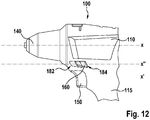
- Fig. 12
- eine schematische Seitenansicht einer erfindungsgemäßen Handwerkzeugmaschine mit einer sechsten Ausführungsform des zweiten Schaltelementes.
-
Figur 1 zeigt eine schematische Explosionsansicht einer Ausführungsform einer erfindungsgemäßen Handwerkzeugmaschine 100, die ein Gehäuse 110 mit einem Handgriff 115 aufweist, welcher am Gehäuse 110 angeordnet ist. Gemäß der dargestellten Ausführungsform ist die Handwerkzeugmaschine 100 sowohl mit einer netzabhängigen Stromversorgung als auch mit einer netzunabhängigen Stromversorgung verwendbar, wobei die Handwerkzeugmaschine 100 zur netzunabhängigen Stromversorgung mechanisch und elektrisch mit einem Energiespeicher, bei dem es sich insbesondere um eine Art von Akku für die Spannungsversorgung des Antriebsmotors handelt, verbindbar ist, welcher im Gehäuse 110, insbesondere im Bereich des Handgriffes 115 angeordnet ist. Ferner sind im Gehäuse 110 ein mit Strom versorgter, elektrischer Antriebsmotor und ein Getriebe 120 angeordnet. Der Antriebsmotor ist über das Getriebe 120 und eine Antriebswelle mit einer Werkzeugaufnahme 140 für ein nicht dargestelltes Werkzeug, beispielsweise einen Bohrer oder einen Bitaufsatz, verbunden. - Die Handwerkzeugmaschine 100 weist ein erstes Schaltelement 150 zum Betätigen einer ersten Schaltereinheit 130 (siehe
Fig. 2, 3 ) für die Energieversorgung des Antriebsmotors auf. Das erste Schaltelement 150 ist vom Benutzer durch eine Druckbewegung manuell betätigbar, um so die Spannungsversorgung für den Antriebsmotor ein- und/oder auszuschalten. Das erste Schaltelement 150 wirkt bei seiner Bewegung direkt und/oder indirekt betätigend auf die erste Schaltereinheit 130 ein. - Bei der in den Figuren lediglich schematisch angedeuteten ersten Schaltereinheit 130 handelt es sich um einen in herkömmlicher Art und Weise ausgebildeten elektrischen Schalter mit einem elektromechanischen Kontaktsystem. Das erste Schaltelement 150 wirkt in bekannter Art und Weise über ein nicht im Einzelnen dargestelltes Verbindungsmittel, das beweglich in das Innere des Gehäuses 110 hineinführt, auf die erste Schaltereinheit 130 ein. Entsprechend kann es sich bei dem ersten Schaltelement 150 auch um einen Sensordruckschalter mit einem Sensor, wie einen Kraftsensor, einen Hallsensor, einen magnetoresistiven Sensor, einen kapazitiven Drucksensor o. dgl. handeln.
- Ein sowohl mit dem ersten Schaltelement 150 als auch mit der ersten Schaltereinheit 130 in Wirkverbindung bringbares Verbindungsmittel 167 überträgt die Bewegung des ersten Schaltelementes 150 auf die erste Schaltereinheit 130.
- Wie anhand von
Fig. 1 zu erkennen ist, ragt das erste Schaltelement 150 aus dem Gehäuse 110 des Handgriffes 115 für den Benutzer manuell zugänglich heraus, so dass in einer an sich bekannten Art und Weise mit Hilfe der ersten Schaltereinheit 130 eine Steuerung und/oder Regelung des Antriebsmotors bevorzugterweise in Abhängigkeit vom Verstellweg des ersten Schaltelementes 150 ermöglicht werden kann. Beispielsweise kann der Benutzer durch entsprechende manuelle Verstellung des ersten Schaltelementes 150 die Drehzahl, das Drehmoment o. dgl. des Antriebsmotors in der Art einer "Gas-Gebe"-Funktion einstellen. - Ferner weist die Handwerkzeugmaschine 100 ein zweites Schaltelement 160 in Form eines Schiebeschalters zum Einstellen der Drehrichtung des Antriebsmotors der Handwerkzeugmaschine 100 auf. Das zweite Schaltelement 160 ist entlang einer Drehachse x der Antriebswelle, insbesondere der Werkzeugaufnahme 140 der Handwerkzeugmaschine 100, verschieblich angeordnet, so dass das zweite Schaltelement 160 bei Betätigung eine Linearbewegung im wesentlichen parallel zu der Drehachse x ausführt und in der dargestellten Ausführungsform zwischen einer ersten Position 182, einer zweiten Position 186 und einer dritten Position 184 hin und her bewegt werden kann. Dabei legen jeweils die erste und zweite Position eine Drehrichtung des Antriebsmotors fest. So ist die erste Position 182 einer ersten Drehrichtung des Antriebsmotors und die zweite Position 184 einer zweiten Drehrichtung des Antriebsmotors zugeordnet, wobei wiederum die erste Drehrichtung des Antriebsmotors einer ersten Drehrichtung 142 der Werkzeugaufnahme 140 und eine zweite Drehrichtung 144 des Antriebsmotors einer zweiten Drehrichtung der Werkzeugaufnahme 140 zugeordnet. Die erste Position 182 liegt gegenüber der zweiten Position 184 näher an der Werkzeugaufnahme 140, wobei die erste Drehrichtung 142 der Werkzeugaufnahme 140 eine Rechtsdrehung und damit ein Eindrehen beispielsweise einer Schraube bewirkt. Demgegenüber liegt die zweite Position 184 gegenüber der ersten Position 182 weiter entfernt von der Werkzeugaufnahme 140 und bewirkt eine Linksdrehung der Werkzeugaufnahme 140 und damit ein Ausdrehen einer Schraube.
- Somit kann der Benutzer der Handwerkzeugmaschine bereits anhand der Positionen 182, 184 des zweiten Schaltelements 160 erkennen, in welchem Arbeitsmodus die Handwerkzeugmaschine 100 arbeitet.
- Ferner kann das zweite Schaltelement 160 zum Beispiel einen Schaltkontakt für die Spannungsversorgung des Antriebsmotors besitzen, um den Antriebsmotor von der Spannungsversorgung zu trennen, wenn die Handwerkzeugmaschine 100 nicht benutzt wird.
- Zusätzlich weist das zweite Schaltelement 160 zwischen der ersten Position 182 und der zweiten Position 184 ein dritte Position 186, eine Mittelstellung, auf, wobei in der dritten Position 186 eine elektrische, elektromechanische und/ oder mechanische Unterbrechung des Motorstroms erfolgt. So kann zum Beispiel die Bedienung der ersten Schaltereinheit 130 über das erste Schaltelement 150 mechanisch gesperrt sein, wobei das zweite Schaltelement 160 bei Bewegung in eine dritte Position 186 verriegelnd auf das erste Schaltelement 150 wirkt. Alternativ kann die Sperrung des ersten Schaltelementes 150 und/oder der ersten Schaltereinheit 130 und damit die Unterbrechung des Motorstroms in der dritten Position 186 des zweiten Schalterelements 160 elektrisch und/oder elektromechanisch, beispielsweise durch die Abgabe eines Signals an eine elektronische Einheit der Handwerkzeugmaschine, insbesondere an die erste Schaltereinheit 130 erfolgen.
- Wie in den
Figuren 2 ,3 , und4 sowie 6 bis 12 dargestellt, gibt es verschiedene Möglichkeiten, eine erfindungsgemäße Linearbewegung des zweiten Schaltelementes 160 umzusetzen. Eine Variante ist inFigur 2 dargestellt, wobei das zweite Schaltelement 160 einen Drehrichtungsschalter 132 betätigt. Der Drehrichtungsschalter 132 ist in der dargestellten Ausführungsform direkt in die erste Schaltereinheit 130 integriert. Das zweite Schaltelement 160 ist an der Außenseite des Gehäuses 110 angebracht und mit einem Schaltsteg 166, der im Inneren des Gehäuses 110 liegt, verbunden. Der Schaltsteg 166 steht mit dem Drehrichtungsschalter 132 über ein Verbindungselement 166 in Eingriff und kann im Wesentlichen parallel zur Drehachse x bewegt werden. Ferner weist diese Schalteranordnung eine Schalterwippe 168 auf, welche quer zur Drehachse x bewegbar ist. Die Umwandlung der Längsbewegung des Schaltsteges 166 in die Querbewegung der Schalterwippe 168 erfolgt über eine Kulissenschaltung 170. - Eine alternative Variante ist in
Figur 3 dargestellt. Im Gegensatz zu der inFigur 2 beschriebenen ersten Variante ist der Schaltsteg 166 direkt mit dem Drehrichtungsschalter 132 über das Verbindungselement 167 verbunden, so dass das Verbindungselement 167 im wesentlichen parallel zur Drehachse x bewegt werden kann. Diese Schalteranordnung weist weder eine Schalterwippe noch eine Kulissenschaltung auf. - In einer weiteren, in den
Figuren 4 und 5 dargestellten Ausführungsform, steht der Schaltsteg 166 über das Verbindungselement 166 und über eine Drehscheibe 169 mit dem Drehrichtungsschalter 132 in Eingriff. Der Schaltsteg 166 kann somit weitestgehend im Wesentlichen parallel zur Drehachse x bewegt werden. Das Verbindungselement 167 ist drehbar mit dem Schaltsteg 166 verbunden, so dass eine entlang der Drehachse x vollzogenen Bewegung über eine Drehbewegung der Drehscheibe 169 und den Drehrichtungsschalter 132 an die erste Schaltereinheit 130 übertragen wird. - Wie in den
Figuren 6 und7 dargestellt, kann das zweite Schaltelement 160 alternativ auch eine zweite Schaltereinheit 190 bedienen, welche die Position 182, 184, 186 des zweiten Schaltelementes 160 elektronisch über Kontaktelemente 192 an die erste Schaltereinheit 130 übermittelt. Dabei kann das zweite Schaltelement 160 als Schiebeschalter oder wie inFigur 7 dargestellt als Kippschalter ausgeführt sein. - In den
Figuren 8 und 9 ist eine vierte Ausführungsform des zweiten Schaltelementes 160 dargestellt. Dabei ist das zweite Schaltelement 160 entlang der Drehachse x in Richtung der Werkzeugaufnahme 140 vor dem ersten Schaltelement 150 in einem Bereich unterhalb der Drehachse x angeordnet und ragt an der Unterseite aus dem Gehäuse 110 heraus. Dabei sind das erste Schaltelement 150 und das zweite Schaltelement 160 entlang einer gemeinsamen, zur Drehachse x im Wesentlichen parallelen Achse x', welche unterhalb des Gehäuses 110 verläuft, hintereinander angeordnet. Entlang der fiktiven Achse x' ist das zweite Schaltelement 160 in Richtung der Werkzeugaufnahme 140 vor dem ersten Schaltelement 150 in Form eines Schiebeschalters im Wesentlichen quer zur Längserstreckung des Handgriffs 115 und quer zur Achse x verschiebbar angeordnet. In dieser Ausführungsform ragt ein erster Abschnitt 161 des zweiten Schaltelementes 160 nach unten aus dem Gehäuse 110 heraus, ferner weist das zweite Schaltelement 160 einen zweiten Abschnitt 162 und einen dritten Abschnitt 163 auf, die beidseitig aus dem Gehäuse 110 herausragen. Auf diese Weise kann der Benutzer der Handwerkzeugmaschine 100 das zweite Schaltelement 160 sowohl über den seitlich aus dem Gehäuse 110 herausragenden ersten Abschnitt 162 und den seitlich aus dem Gehäuse 110 herausragenden dritten Abschnitt 163 als auch über den unter dem Gehäuse 110 herausragenden ersten Abschnitt 161 des zweiten Schaltelementes 160 bedienen. Das zweite Schaltelement 160 kann somit einfach und komfortabel mit dem Daumen, dem Zeigefinger oder einem anderen Finger bedient werden, so dass es unerheblich ist, ob es sich bei dem Bediener um einen Rechtshänder oder Linkshänder handelt. - Grundsätzlich kann das zweite Schaltelement 160 einstückig ausgebildet sein. Alternativ ist aber auch eine mehrstückige Ausgestaltung wie in den
Figuren 10 und 11 dargestellt denkbar, wobei in der fünften Ausführungsform des zweiten Schaltelementes 160, die in denFiguren 10 und 11 dargestellt ist, die Abschnitte 163, 162 einstückig ausgeformt sind und auf den ersten Abschnitt 161 aufgesteckt werden können. Im Gegensatz zu der in denFiguren 8 und 9 dargestellten Ausführungsform verlaufen die Abschnitte 162, 163 des zweiten Schaltelementes 160 unterhalb des Gehäuses 110 und ragen nicht durch das Gehäuse 110 hindurch. Dabei weist das zweite Schaltelement 160 eine Form auf, die einer Kontur des Gehäuses 110 derart folgt, dass das zweite Schaltelement beidseitig bedienbar ist. Durch die mehrstückige Ausführungsform kann das zweite Schaltelement 160 variabel umgestaltet werden, so dass es für den Bediener möglich ist, selbständig zu entscheiden, ob er die seitlichen Abschnitte 162, 163 montiert haben möchte. Allerdings ist grundsätzlich sowohl eine einstückige als auch eine mehrstückige Ausgestaltung des zweiten Schaltelementes 160 möglich. - Bei der in
Figur 12 dargestellten sechsten Ausführungsform des zweiten Schaltelementes 160 ist das zweite Schaltelement 160 oberhalb des ersten Schaltelementes 150 angeordnet. Dabei ist das zweite Schaltelement 160 entlang einer zur Drehachse x im Wesentlichen parallelen Achse x" verschieblich angeordnet, so dass das zweite Schaltelement 160 bei Betätigung eine Linearbewegung im Wesentlichen parallel zu der Drehachse x ausführt und in der dargestellten Ausführungsform zwischen einer ersten Position 182, einer zweiten Position und einer dritten Position 184 hin und her bewegt werden kann. Die Achse x" verläuft unterhalb der Drehachse x im unteren Bereich des Gehäuses 110 und über der fiktiven Achse x'. Die Drehachse x und die fiktive Achse x" verlaufen dabei parallel, aber versetzt zueinander. In dieser Ausführungsform ist das zweite Schaltelement 160 vollständig in dem unteren Bereich des Gehäuses 110 integriert angeordnet und ragt seitlich aus dem Gehäuse 110 heraus. - Wesentlich ist, dass bei allen Varianten das zweite Schaltelement 160 bei Betätigung eine Linearbewegung im Wesentlichen parallel zur Drehachse x ausführt. Wesentlich ist ferner, dass bei allen Varianten das zweite Schaltelement 160 entlang der Drehachse x vor dem ersten Schaltelement 150 angeordnet, so dass es möglich ist, das zweite Schaltelement 160 je nach Griffposition mit dem Zeigefinger oder Mittelfinger zu betätigen. Das zweite Schaltelement 160 ist entlang der Drehachse x in Richtung Werkzeugaufnahme 140 vor dem ersten Schaltelement 150 angeordnet. Dabei ist der Abstand zwischen dem ersten Schaltelement 150 und dem zweiten Schaltelement 160 so gewählt, dass eine Einhandbedienung der Handwerkzeugmaschine 100 möglich ist. Insbesondere erlaubt die Anordnung des zweiten Schaltelements 160 relativ zu dem ersten Schaltelement 150 eine Einhandbedienung beider Schaltelemente 150, 160. Das zweite Schaltelement 160 ist ferner in einem Bereich unterhalb der Drehachse x angeordnet. In der dargestellten Ausführungsform, zum Beispiel nach
Fig. 1, 6 und 8 bis 11 , ist das zweite Schaltelement 160 an der Unterseite des Gehäuses 110 angeordnet. Dabei sind das erste Schaltelement 150 und das zweite Schaltelement 160 entlang der gemeinsamen, zur Drehachse x im Wesentlichen parallelen Achse x', welche unterhalb des Gehäuses 110 verläuft, hintereinander angeordnet. Entlang der fiktiven Achse x' ist das zweite Schaltelement 160 in Richtung der Werkzeugaufnahme 140 vor dem ersten Schaltelement 150 angeordnet. In dieser Ausführungsform ragt das erste Schaltelement 160 nach unten aus dem Gehäuse 110 heraus. - In einer alternativen, nicht dargestellten Ausführungsform ist das zweite Schaltelement 160 in Richtung der Werkzeugaufnahme 140 vor dem ersten Schaltelement 150 und oberhalb des ersten Schaltelements 150 angeordnet. Dabei ist das zweite Schaltelement 160 entlang der zur Drehachse x im Wesentlichen parallelen Achse x" angeordnet, welche unterhalb der Drehachse x im unteren Bereich des Gehäuses 110 und über der fiktiven Achse x' verläuft. Die fiktiven Achsen x' und x" verlaufen dabei parallel, aber versetzt zueinander. In dieser Ausführungsform ragt das zweite Schaltelement 160 im unteren Bereich des Gehäuses 110 seitlich aus dem Gehäuse 110 heraus.
- In einer weiteren nicht dargestellten alternativen Ausführungsform ist das zweite Schaltelement 160 in wenigstens zwei Betätigungselemente aufgeteilt, wobei vorteilhafterweise die Betätigungselemente im wesentlichen parallel gegenüberliegend zueinander entlang der Drehachse x an der Außenseite des Gehäuses 110 angebracht sind, so dass eine Bedienung des zweiten Schaltelementes 160 sowohl mit dem Zeigefinger oder Mittelfinger der rechten und der linken Hand erfolgen kann. Die zwei Betätigungselemente sind dabei insbesondere zusammenhängend ausgeführt.
- Die Erfindung ist nicht auf das beschriebene und dargestellte Ausführungsbeispiel beschränkt. Sie umfasst vielmehr auch alle fachmännischen Weiterbildungen im Rahmen der durch die Patentansprüche definierten Erfindung. So kann die Erfindung, insbesondere die beschriebene Schalteranordnung, nicht nur bei Akku-Elektrowerkzeugen sondern auch bei sonstigen Elektrogeräten, die mit einem insbesondere wechselbar ausgestalteten Energiespeicher versehen sind, wie Elektrohaushaltsgeräten, Elektrogartengeräten, Werkzeugmaschinen o. dgl., in vielfältiger Art und Weise Verwendung finden.
- Neben den beschriebenen und abgebildeten Ausführungsformen sind weitere Ausführungsformen vorstellbar, welche weitere Abwandlungen sowie Kombinationen von Merkmalen umfassen können.
Claims (17)
- Handwerkzeugmaschine (100) umfassend ein Gehäuse (110) mit einem Handgriff (115), ein in dem Gehäuse (110) angeordnetes Getriebe (120) zur Übertragung eines von einem Antriebsmotor erzeugten Drehmomentes auf eine um eine Drehachse (x) rotierende Werkzeugaufnahme (140), sowie eine in dem Gehäuse (110) angeordnete erste Schaltereinheit (130) zur Steuerung des Antriebsmotors mit einem ersten Schaltelement (150) und einem zweiten Schaltelement (160) zur Bedienung der Schaltereinheit (130), wobei über das erste Schaltelement (150) und zweite Schaltelement (160) Steuergrößen des Antriebsmotor von einem Bediener beeinflusst werden, wobei über das zweite Schaltelement (160) die Drehrichtung des Antriebsmotors regelbar ist, und wobei das zweite Schaltelement (160) bei Betätigung eine Linearbewegung im Wesentlichen parallel zur Drehachse (x) ausführt, dadurch gekennzeichnet, dass das zweite Schaltelement (160) entlang der Drehachse (x) in Richtung Werkzeugaufnahme (140) vor dem ersten Schaltelement (150) und in einem Bereich unterhalb der Drehachse (x) angeordnet ist, wobei das zweite Schaltelement (160) an der Unterseite des Gehäuses (110) angeordnet ist.
- Handwerkzeugmaschine (100) nach Anspruch 1, wobei das erste Schaltelement (160) nach unten aus dem Gehäuse (110) heraus ragt.
- Handwerkzeugmaschine (100) nach einem der Ansprüche 1 bis 2, wobei das zweite Schaltelement (160) in wenigstens zwei Positionen einrastet, wobei eine erste Position (182) einer ersten Drehrichtung des Antriebsmotors entspricht, wobei die erste Drehrichtung des Antriebsmotors einer ersten Schraubrichtung (142) der Werkzeugaufnahme (140) zugeordnet ist und wobei eine zweite Position (184) einer zweiten Drehrichtung des Antriebsmotors entspricht, wobei die zweite Drehrichtung des Antriebsmotors einer zweiten Schraubrichtung (144) der Werkzeugaufnahme (140) zugeordnet ist.
- Handwerkzeugmaschine (100) nach Anspruch 3, wobei die erste Position (182) gegenüber der zweiten Position (184) näher an der Werkzeugaufnahme (140) liegt und die erste Schraubrichtung (142) eine Rechtsdrehung der Werkzeugaufnahme (140) bewirkt und wobei die zweite Position (184) gegenüber der ersten Position (182) weiter entfernt von der Werkzeugaufnahme (140) liegt und die zweite Schraubrichtung (144) eine Linksdrehung der Werkzeugaufnahme (140) bewirkt.
- Handwerkzeugmaschine (100) nach einem der Ansprüche 1 bis 4, wobei das zweite Schaltelement (160) in einer dritten Position (186) einrastet, wobei in der dritten Position (186) eine elektrische, elektromechanische und/ oder mechanische Unterbrechung des Motorstroms erfolgt.
- Handwerkzeugmaschine (100) nach einem der Ansprüche 1 bis 5, wobei das zweite Schaltelement (160) einen Drehrichtungsschalter (132) der ersten Schaltereinheit (130) betätigt.
- Handwerkzeugmaschine (100) nach einem der Ansprüche 1 bis 6, wobei das zweite Schaltelement (160) an der Gehäuseaußenseite angebracht ist und mit einem Schaltsteg (166) im Inneren des Gehäuses (110) verbunden ist, wobei der Schaltsteg (166) mit dem Drehrichtungsschalter (132) in Eingriff steht und im Wesentlichen parallel zur Drehachse (x) bewegt werden kann.
- Handwerkzeugmaschine (100) nach Anspruch 7, wobei der Eingriff über ein Verbindungselement (167) erfolgt, welches im Wesentlichen parallel zur Drehachse (x) bewegbar ist.
- Handwerkzeugmaschine (100) nach Anspruch 7 oder 8, wobei der Eingriff über eine Drehscheibe (16) erfolgt, die um eine Achse (y) drehbar angeordnet ist.
- Handwerkzeugmaschine (100) nach Anspruch 7 oder 8, wobei der Eingriff über eine Schalterwippe (168) erfolgt, die im Wesentlichen quer zur Drehachse (x) bewegbar ist.
- Handwerkzeugmaschine (100) nach Anspruch 10, wobei die Umwandlung der Längsbewegung des Schaltsteges (166) in die Querbewegung der Schalterwippe (168) über eine Kulissenschaltung (170) erfolgt.
- Handwerkzeugmaschine (100) nach einem der Ansprüche 1 bis 11, wobei das zweite Schaltelement (160) eine zweite Schaltereinheit (190) bedient, welche die Position des zweiten Schaltelementes (160) elektronisch an die erste Schaltereinheit (130) übermittelt, wobei die Position des zweiten Schaltelements (160) von einem Sensor, insbesondere einem induktiv, kapazitiv, magnetisch und/oder optisch arbeitenden Sensor erfassbar ist.
- Handwerkzeugmaschine (100) nach Anspruch 1 bis 12, wobei das zweite Schaltelement (160) mehrere Abschnitte (161, 162, 163) aufweist, wobei die Abschnitte (161, 162, 163) an der Gehäuseaußenseite angeordnet und mit einem Schaltsteg (166) im Inneren des Gehäuses (110) verbunden sind und jeweils in unterschiedliche Richtungen aus dem Gehäuse (110) herausragen.
- Handwerkzeugmaschine (100) nach einem der Ansprüche 1 bis 13, wobei das zweite Schaltelement (160) wenigstens zwei Abschnitte (162, 163) aufweist, wobei die beiden Abschnitte (162, 163) im Wesentlichen parallel gegenüberliegend zueinander entlang einer Drehachse (x) an der Außenseite des Gehäuses (110) angeordnet sind.
- Handwerkzeugmaschine (100) nach einem der Ansprüche 1 bis 14, wobei das zweite Schaltelement (160) eine Form aufweist, die einer Kontur des Gehäuses (110) derart folgt, dass das zweite Schaltelement beidseitig bedienbar ist.
- Handwerkzeugmaschine (100) nach einem der Ansprüche 1 bis 15, wobei das zweite Schaltelement (160) zumindest abschnittsweise innerhalb des Gehäuses (110) verläuft.
- Handwerkzeugmaschine (100) nach einem der vorhergehenden Ansprüche, wobei die Handwerkzeugmaschine (100) ein Stabschrauber, eine Schlagbohrmaschinen, ein Multifunktionswerkzeug, ein Bohrschrauber, ein Akku-Bohrer, ein Akku-Schrauber und/ oder ein Akku-Bohrschrauber mit einem Getriebe (120) zur Übertragung eines von dem Antriebsmotor erzeugten Drehmomentes auf eine Antriebswelle ist.
Applications Claiming Priority (2)
| Application Number | Priority Date | Filing Date | Title |
|---|---|---|---|
| DE102014209354 | 2014-05-16 | ||
| DE102014217863.0A DE102014217863A1 (de) | 2014-05-16 | 2014-09-08 | Handwerkzeugmaschine |
Publications (2)
| Publication Number | Publication Date |
|---|---|
| EP2944433A1 EP2944433A1 (de) | 2015-11-18 |
| EP2944433B1 true EP2944433B1 (de) | 2017-06-14 |
Family
ID=53269301
Family Applications (1)
| Application Number | Title | Priority Date | Filing Date |
|---|---|---|---|
| EP15165254.2A Active EP2944433B1 (de) | 2014-05-16 | 2015-04-27 | Handwerkzeugmaschine |
Country Status (4)
| Country | Link |
|---|---|
| US (1) | US10454391B2 (de) |
| EP (1) | EP2944433B1 (de) |
| CN (1) | CN105082083B (de) |
| DE (1) | DE102014217863A1 (de) |
Cited By (4)
| Publication number | Priority date | Publication date | Assignee | Title |
|---|---|---|---|---|
| CN108927545A (zh) * | 2018-08-09 | 2018-12-04 | 台州来智科技有限公司 | 一种冷却水循环双模式驱动选择钻孔装置 |
| WO2021173602A1 (en) * | 2020-02-24 | 2021-09-02 | Milwaukee Electric Tool Corporation | Impact tool |
| USD948978S1 (en) | 2020-03-17 | 2022-04-19 | Milwaukee Electric Tool Corporation | Rotary impact wrench |
| US11511400B2 (en) | 2018-12-10 | 2022-11-29 | Milwaukee Electric Tool Corporation | High torque impact tool |
Families Citing this family (10)
| Publication number | Priority date | Publication date | Assignee | Title |
|---|---|---|---|---|
| US10131042B2 (en) | 2013-10-21 | 2018-11-20 | Milwaukee Electric Tool Corporation | Adapter for power tool devices |
| KR101641928B1 (ko) * | 2015-04-08 | 2016-07-25 | 사이언스메딕 주식회사 | 방향전환기능을 구비한 외과수술용 핸드피스 |
| DE102015226087A1 (de) * | 2015-12-18 | 2017-06-22 | Robert Bosch Gmbh | Handwerkzeugmaschine mit einstellbarer Drehrichtung |
| US11623335B2 (en) | 2017-11-15 | 2023-04-11 | Defond Components Limited | Control assembly for use in operation of an electric device |
| DE102018206882A1 (de) * | 2018-05-04 | 2019-11-07 | Robert Bosch Gmbh | Elektroschraubergehäuse |
| JP7320419B2 (ja) | 2019-09-27 | 2023-08-03 | 株式会社マキタ | 回転打撃工具 |
| JP7386027B2 (ja) * | 2019-09-27 | 2023-11-24 | 株式会社マキタ | 回転打撃工具 |
| CN111300322A (zh) * | 2020-03-17 | 2020-06-19 | 广东电网有限责任公司 | 一种电动拧紧工具 |
| CN111590524B (zh) * | 2020-06-11 | 2024-11-05 | 浙江德硕科技股份有限公司 | 多功能动力工具的头身快换结构及多功能动力工具 |
| CN112192494A (zh) * | 2020-10-15 | 2021-01-08 | 东莞市冠佳电子设备有限公司 | 一种万用驱动结构 |
Family Cites Families (46)
| Publication number | Priority date | Publication date | Assignee | Title |
|---|---|---|---|---|
| US3221192A (en) * | 1962-10-11 | 1965-11-30 | Porter Co H K | Variable speed hand tool |
| US3579002A (en) * | 1970-03-31 | 1971-05-18 | Black & Decker Mfg Co | Reversing switch for power tools |
| US4342931A (en) * | 1981-01-29 | 1982-08-03 | Black & Decker Inc. | Brush-shifting and trigger-switch arrangements for a portable tool |
| US4682918A (en) | 1984-04-16 | 1987-07-28 | Milwaukee Electric Tool Corporation | Keyless impacting chuck |
| US4592144A (en) * | 1984-06-22 | 1986-06-03 | The Singer Company | Molded scroller saw lock button spring |
| US5365155A (en) * | 1990-10-22 | 1994-11-15 | Marquardt Gmbh | Rotational speed control and use of same to control the rotational speed of an electric hand tool motor |
| US5089729A (en) * | 1991-03-14 | 1992-02-18 | Black & Decker Inc. | Power tool with brush shifting and reversing switch assembly |
| US5561734A (en) * | 1992-08-13 | 1996-10-01 | Milwaukee Electric Tool Corporation | Dial speed control for hand-held power tool |
| US5261140A (en) * | 1992-08-14 | 1993-11-16 | Szymanski Thomas A | Reversible rotary shampoo machine or floor waxer |
| DE19546328B4 (de) * | 1995-12-12 | 2007-12-13 | Robert Bosch Gmbh | Handwerkzeugmaschine mit einem drehbaren Handgriff |
| US5813859A (en) * | 1997-01-23 | 1998-09-29 | Hajjar; Victor J. | Method and apparatus for tooth restoration |
| US6058797A (en) * | 1998-11-24 | 2000-05-09 | Teleflex Incorporated | Clip-on shifter knob |
| US6138346A (en) * | 1998-12-21 | 2000-10-31 | Connectool Inc. | Portable hand-held battery-powered crimping tool |
| DE29904051U1 (de) * | 1999-03-05 | 1999-06-17 | Chung, Lee Hsin-Chih, Chungli, Taoyuan | Schalteinrichtung für ein Reduktionsgetriebe |
| JP2000288960A (ja) * | 1999-04-01 | 2000-10-17 | Mobiletron Electronics Co Ltd | 電動工具の速度を変える制御機構 |
| US6536536B1 (en) * | 1999-04-29 | 2003-03-25 | Stephen F. Gass | Power tools |
| DE19937767B4 (de) * | 1999-08-10 | 2004-09-09 | Hilti Ag | Handgeführter elektrischer Kombihammer |
| JP3768400B2 (ja) * | 2000-11-17 | 2006-04-19 | 佐鳥エス・テック株式会社 | 電動工具スイッチ |
| JP3853590B2 (ja) * | 2000-12-15 | 2006-12-06 | 株式会社マキタ | 電動工具 |
| AUPR272101A0 (en) * | 2001-01-24 | 2001-02-22 | Bayly Design Associates Pty Ltd | Power tool |
| DE10222824A1 (de) * | 2002-05-21 | 2003-12-04 | Hilti Ag | Elektrowerkzeug mit mehrstufigem Getriebe |
| GB0226523D0 (en) * | 2002-11-14 | 2002-12-18 | Black & Decker Inc | Electric motor driven hand-held tool |
| US7066692B2 (en) * | 2003-01-16 | 2006-06-27 | Kuhn Jayme K | Dual chuck electrical hand drill |
| DE20305224U1 (de) * | 2003-03-31 | 2003-06-05 | Hilti Ag, Schaan | Handwerkzeug mit Funktionsstufenanzeige |
| JP2005066785A (ja) | 2003-08-26 | 2005-03-17 | Matsushita Electric Works Ltd | 電動工具 |
| DE10353302A1 (de) * | 2003-11-11 | 2005-06-09 | C. & E. Fein Gmbh | Elektrowerkzeug und Verfahren zur Steuerung eines Elektrowerkzeugs |
| DE102004051913A1 (de) * | 2004-08-09 | 2006-02-23 | Robert Bosch Gmbh | Akkuschrauber |
| DE102005038919A1 (de) * | 2005-08-17 | 2007-03-15 | BSH Bosch und Siemens Hausgeräte GmbH | Elektromotorisches Küchengerät mit elektrischer oder elektronischer Verriegelung |
| CN101253015A (zh) * | 2005-08-29 | 2008-08-27 | 迪美科技控股有限公司 | 动力工具 |
| TWM295562U (en) * | 2005-12-15 | 2006-08-11 | Aebos Technology Co Ltd | Electric powered hand tool |
| US7464430B2 (en) * | 2006-01-03 | 2008-12-16 | Ehsan Filsouf | Electric toothbrush |
| US7565935B1 (en) * | 2006-03-06 | 2009-07-28 | Phillips Robert E | Powered tap driver with rotary control structure |
| DE102006059078A1 (de) * | 2006-12-14 | 2008-06-19 | Robert Bosch Gmbh | Elektrogerät mit aufgerastetem drehbarem Bedienungselement |
| US8047100B2 (en) * | 2008-02-15 | 2011-11-01 | Black & Decker Inc. | Tool assembly having telescoping fastener support |
| US9193053B2 (en) | 2008-09-25 | 2015-11-24 | Black & Decker Inc. | Hybrid impact tool |
| DE102008042426A1 (de) * | 2008-09-29 | 2010-04-01 | Robert Bosch Gmbh | Handwerkzeugmaschine |
| US8251158B2 (en) * | 2008-11-08 | 2012-08-28 | Black & Decker Inc. | Multi-speed power tool transmission with alternative ring gear configuration |
| CN101786179B (zh) * | 2009-01-23 | 2012-01-04 | 车王电子(宁波)有限公司 | 电动工具 |
| DE102009012715A1 (de) * | 2009-03-11 | 2010-09-16 | Marquardt Gmbh | Elektrischer Schalter |
| DE102009054927B4 (de) * | 2009-12-18 | 2025-12-18 | Robert Bosch Gmbh | Handwerkzeugmaschine, insbesondere Akkuhandwerkzeugmaschine |
| DE102011004364A1 (de) * | 2011-02-18 | 2012-08-23 | Robert Bosch Gmbh | Handwerkzeugmaschine, insbesondere Akkuschrauber |
| JP5760957B2 (ja) | 2011-11-02 | 2015-08-12 | マックス株式会社 | 回転工具 |
| DE102012206884A1 (de) * | 2012-04-26 | 2013-10-31 | Robert Bosch Gmbh | Handwerkzeugmaschine |
| US9242362B2 (en) * | 2012-09-07 | 2016-01-26 | Robert Bosch Gmbh | Slide switch for a power tool |
| DE102012220423A1 (de) * | 2012-11-09 | 2014-05-15 | Robert Bosch Gmbh | Handwerkzeugmaschine |
| JP6105454B2 (ja) * | 2013-11-26 | 2017-03-29 | 株式会社マキタ | 作業工具 |
-
2014
- 2014-09-08 DE DE102014217863.0A patent/DE102014217863A1/de not_active Withdrawn
-
2015
- 2015-04-27 EP EP15165254.2A patent/EP2944433B1/de active Active
- 2015-05-15 CN CN201510425204.4A patent/CN105082083B/zh active Active
- 2015-05-15 US US14/713,304 patent/US10454391B2/en active Active
Cited By (8)
| Publication number | Priority date | Publication date | Assignee | Title |
|---|---|---|---|---|
| CN108927545A (zh) * | 2018-08-09 | 2018-12-04 | 台州来智科技有限公司 | 一种冷却水循环双模式驱动选择钻孔装置 |
| US11511400B2 (en) | 2018-12-10 | 2022-11-29 | Milwaukee Electric Tool Corporation | High torque impact tool |
| US11597061B2 (en) | 2018-12-10 | 2023-03-07 | Milwaukee Electric Tool Corporation | High torque impact tool |
| WO2021173602A1 (en) * | 2020-02-24 | 2021-09-02 | Milwaukee Electric Tool Corporation | Impact tool |
| EP4110554A4 (de) * | 2020-02-24 | 2024-03-27 | Milwaukee Electric Tool Corporation | Schlagwerkzeug |
| US12157208B2 (en) | 2020-02-24 | 2024-12-03 | Milwaukee Electric Tool Corporation | Impact tool |
| USD948978S1 (en) | 2020-03-17 | 2022-04-19 | Milwaukee Electric Tool Corporation | Rotary impact wrench |
| USD971706S1 (en) | 2020-03-17 | 2022-12-06 | Milwaukee Electric Tool Corporation | Rotary impact wrench |
Also Published As
| Publication number | Publication date |
|---|---|
| US10454391B2 (en) | 2019-10-22 |
| CN105082083B (zh) | 2019-06-28 |
| DE102014217863A1 (de) | 2015-11-19 |
| US20150333664A1 (en) | 2015-11-19 |
| CN105082083A (zh) | 2015-11-25 |
| EP2944433A1 (de) | 2015-11-18 |
Similar Documents
| Publication | Publication Date | Title |
|---|---|---|
| EP2944433B1 (de) | Handwerkzeugmaschine | |
| DE102013222550B4 (de) | Handwerkzeugmaschine | |
| DE102011004495B4 (de) | Handwerkzeugmaschine | |
| EP3003648B1 (de) | Handwerkzeugmaschine mit einem schaltbaren getriebe | |
| DE102011078082B4 (de) | Handwerkzeugmaschine, insbesondere Bohr- oder Schraubgerät | |
| EP0463521B1 (de) | Verfahren und Vorrichtung zur Steuerung des Betriebs von Elektrohandgeräten | |
| EP2011606B1 (de) | Vibrierende Handwerkzeugmaschine mit einem Arretierschalter des Motorschalters | |
| EP1895555A2 (de) | Handwerkzeugmaschine | |
| DE102007019436B4 (de) | Handwerkzeugmaschine, insbesondere Bohr- oder Schraubgeräte | |
| EP1671750B1 (de) | Maschine zum Schrauben oder Bohren und Verfahren zur Steuerung der Drehrichtung einer solchen Maschine | |
| DE102009001132B4 (de) | Elektrowerkzeug | |
| EP2101957B1 (de) | Elektrogerät mit aufgerastetem drehbarem bedienungselement | |
| EP3389942B1 (de) | Handwerkzeugmaschine mit einem schlagwerk | |
| EP2212062B1 (de) | Handwerkzeugmaschine | |
| WO2014108110A1 (de) | Schalt- und steuereinrichtung für ein elektrowerkzeug und verfahren zu dessen steuerung | |
| EP2240304B1 (de) | Elektrowerkzeug | |
| WO2017021144A1 (de) | Handwerkzeugmaschine | |
| DE3316111A1 (de) | Elektrohandwerkzeug mit steuerung fuer verschiedene funktionen | |
| DE102017123163B4 (de) | Bedienvorrichtung zum Steuern eines Werkzeuges oder einer Arbeitsmaschine | |
| WO2012150076A1 (de) | Werkzeugmaschinenschaltvorrichtung | |
| EP2655018A1 (de) | Handwerkzeugmaschine | |
| EP3222389A1 (de) | Elektrische handwerkzeugmaschine | |
| DE102016205937A1 (de) | Handwerkzeugmaschine mit einem schaltbaren Getriebe | |
| DE102011004295B4 (de) | Fernbetätigungseinrichtung für ein Bodenreinigungsgerät, Bodenreinigungsgerät und Verfahren zum Betrieb eines Bodenreinigungsgeräts | |
| EP1472708B1 (de) | Elektrische schaltanordnung für ein elektrowerkzeug |
Legal Events
| Date | Code | Title | Description |
|---|---|---|---|
| PUAI | Public reference made under article 153(3) epc to a published international application that has entered the european phase |
Free format text: ORIGINAL CODE: 0009012 |
|
| AK | Designated contracting states |
Kind code of ref document: A1 Designated state(s): AL AT BE BG CH CY CZ DE DK EE ES FI FR GB GR HR HU IE IS IT LI LT LU LV MC MK MT NL NO PL PT RO RS SE SI SK SM TR |
|
| AX | Request for extension of the european patent |
Extension state: BA ME |
|
| 17P | Request for examination filed |
Effective date: 20160518 |
|
| RBV | Designated contracting states (corrected) |
Designated state(s): AL AT BE BG CH CY CZ DE DK EE ES FI FR GB GR HR HU IE IS IT LI LT LU LV MC MK MT NL NO PL PT RO RS SE SI SK SM TR |
|
| GRAP | Despatch of communication of intention to grant a patent |
Free format text: ORIGINAL CODE: EPIDOSNIGR1 |
|
| INTG | Intention to grant announced |
Effective date: 20170105 |
|
| GRAS | Grant fee paid |
Free format text: ORIGINAL CODE: EPIDOSNIGR3 |
|
| GRAA | (expected) grant |
Free format text: ORIGINAL CODE: 0009210 |
|
| AK | Designated contracting states |
Kind code of ref document: B1 Designated state(s): AL AT BE BG CH CY CZ DE DK EE ES FI FR GB GR HR HU IE IS IT LI LT LU LV MC MK MT NL NO PL PT RO RS SE SI SK SM TR |
|
| REG | Reference to a national code |
Ref country code: GB Ref legal event code: FG4D Free format text: NOT ENGLISH |
|
| REG | Reference to a national code |
Ref country code: CH Ref legal event code: EP Ref country code: AT Ref legal event code: REF Ref document number: 900514 Country of ref document: AT Kind code of ref document: T Effective date: 20170615 |
|
| REG | Reference to a national code |
Ref country code: IE Ref legal event code: FG4D Free format text: LANGUAGE OF EP DOCUMENT: GERMAN |
|
| REG | Reference to a national code |
Ref country code: DE Ref legal event code: R096 Ref document number: 502015001206 Country of ref document: DE |
|
| REG | Reference to a national code |
Ref country code: NL Ref legal event code: MP Effective date: 20170614 |
|
| REG | Reference to a national code |
Ref country code: LT Ref legal event code: MG4D |
|
| PG25 | Lapsed in a contracting state [announced via postgrant information from national office to epo] |
Ref country code: HR Free format text: LAPSE BECAUSE OF FAILURE TO SUBMIT A TRANSLATION OF THE DESCRIPTION OR TO PAY THE FEE WITHIN THE PRESCRIBED TIME-LIMIT Effective date: 20170614 Ref country code: GR Free format text: LAPSE BECAUSE OF FAILURE TO SUBMIT A TRANSLATION OF THE DESCRIPTION OR TO PAY THE FEE WITHIN THE PRESCRIBED TIME-LIMIT Effective date: 20170915 Ref country code: NO Free format text: LAPSE BECAUSE OF FAILURE TO SUBMIT A TRANSLATION OF THE DESCRIPTION OR TO PAY THE FEE WITHIN THE PRESCRIBED TIME-LIMIT Effective date: 20170914 Ref country code: LT Free format text: LAPSE BECAUSE OF FAILURE TO SUBMIT A TRANSLATION OF THE DESCRIPTION OR TO PAY THE FEE WITHIN THE PRESCRIBED TIME-LIMIT Effective date: 20170614 Ref country code: FI Free format text: LAPSE BECAUSE OF FAILURE TO SUBMIT A TRANSLATION OF THE DESCRIPTION OR TO PAY THE FEE WITHIN THE PRESCRIBED TIME-LIMIT Effective date: 20170614 |
|
| PG25 | Lapsed in a contracting state [announced via postgrant information from national office to epo] |
Ref country code: NL Free format text: LAPSE BECAUSE OF FAILURE TO SUBMIT A TRANSLATION OF THE DESCRIPTION OR TO PAY THE FEE WITHIN THE PRESCRIBED TIME-LIMIT Effective date: 20170614 Ref country code: RS Free format text: LAPSE BECAUSE OF FAILURE TO SUBMIT A TRANSLATION OF THE DESCRIPTION OR TO PAY THE FEE WITHIN THE PRESCRIBED TIME-LIMIT Effective date: 20170614 Ref country code: LV Free format text: LAPSE BECAUSE OF FAILURE TO SUBMIT A TRANSLATION OF THE DESCRIPTION OR TO PAY THE FEE WITHIN THE PRESCRIBED TIME-LIMIT Effective date: 20170614 Ref country code: SE Free format text: LAPSE BECAUSE OF FAILURE TO SUBMIT A TRANSLATION OF THE DESCRIPTION OR TO PAY THE FEE WITHIN THE PRESCRIBED TIME-LIMIT Effective date: 20170614 Ref country code: BG Free format text: LAPSE BECAUSE OF FAILURE TO SUBMIT A TRANSLATION OF THE DESCRIPTION OR TO PAY THE FEE WITHIN THE PRESCRIBED TIME-LIMIT Effective date: 20170914 |
|
| PG25 | Lapsed in a contracting state [announced via postgrant information from national office to epo] |
Ref country code: EE Free format text: LAPSE BECAUSE OF FAILURE TO SUBMIT A TRANSLATION OF THE DESCRIPTION OR TO PAY THE FEE WITHIN THE PRESCRIBED TIME-LIMIT Effective date: 20170614 Ref country code: SK Free format text: LAPSE BECAUSE OF FAILURE TO SUBMIT A TRANSLATION OF THE DESCRIPTION OR TO PAY THE FEE WITHIN THE PRESCRIBED TIME-LIMIT Effective date: 20170614 Ref country code: CZ Free format text: LAPSE BECAUSE OF FAILURE TO SUBMIT A TRANSLATION OF THE DESCRIPTION OR TO PAY THE FEE WITHIN THE PRESCRIBED TIME-LIMIT Effective date: 20170614 Ref country code: RO Free format text: LAPSE BECAUSE OF FAILURE TO SUBMIT A TRANSLATION OF THE DESCRIPTION OR TO PAY THE FEE WITHIN THE PRESCRIBED TIME-LIMIT Effective date: 20170614 |
|
| PG25 | Lapsed in a contracting state [announced via postgrant information from national office to epo] |
Ref country code: ES Free format text: LAPSE BECAUSE OF FAILURE TO SUBMIT A TRANSLATION OF THE DESCRIPTION OR TO PAY THE FEE WITHIN THE PRESCRIBED TIME-LIMIT Effective date: 20170614 Ref country code: IS Free format text: LAPSE BECAUSE OF FAILURE TO SUBMIT A TRANSLATION OF THE DESCRIPTION OR TO PAY THE FEE WITHIN THE PRESCRIBED TIME-LIMIT Effective date: 20171014 Ref country code: PL Free format text: LAPSE BECAUSE OF FAILURE TO SUBMIT A TRANSLATION OF THE DESCRIPTION OR TO PAY THE FEE WITHIN THE PRESCRIBED TIME-LIMIT Effective date: 20170614 Ref country code: SM Free format text: LAPSE BECAUSE OF FAILURE TO SUBMIT A TRANSLATION OF THE DESCRIPTION OR TO PAY THE FEE WITHIN THE PRESCRIBED TIME-LIMIT Effective date: 20170614 Ref country code: IT Free format text: LAPSE BECAUSE OF FAILURE TO SUBMIT A TRANSLATION OF THE DESCRIPTION OR TO PAY THE FEE WITHIN THE PRESCRIBED TIME-LIMIT Effective date: 20170614 |
|
| REG | Reference to a national code |
Ref country code: DE Ref legal event code: R097 Ref document number: 502015001206 Country of ref document: DE |
|
| PLBE | No opposition filed within time limit |
Free format text: ORIGINAL CODE: 0009261 |
|
| STAA | Information on the status of an ep patent application or granted ep patent |
Free format text: STATUS: NO OPPOSITION FILED WITHIN TIME LIMIT |
|
| REG | Reference to a national code |
Ref country code: FR Ref legal event code: PLFP Year of fee payment: 4 |
|
| PG25 | Lapsed in a contracting state [announced via postgrant information from national office to epo] |
Ref country code: DK Free format text: LAPSE BECAUSE OF FAILURE TO SUBMIT A TRANSLATION OF THE DESCRIPTION OR TO PAY THE FEE WITHIN THE PRESCRIBED TIME-LIMIT Effective date: 20170614 |
|
| 26N | No opposition filed |
Effective date: 20180315 |
|
| PG25 | Lapsed in a contracting state [announced via postgrant information from national office to epo] |
Ref country code: SI Free format text: LAPSE BECAUSE OF FAILURE TO SUBMIT A TRANSLATION OF THE DESCRIPTION OR TO PAY THE FEE WITHIN THE PRESCRIBED TIME-LIMIT Effective date: 20170614 |
|
| PG25 | Lapsed in a contracting state [announced via postgrant information from national office to epo] |
Ref country code: MT Free format text: LAPSE BECAUSE OF FAILURE TO SUBMIT A TRANSLATION OF THE DESCRIPTION OR TO PAY THE FEE WITHIN THE PRESCRIBED TIME-LIMIT Effective date: 20170614 |
|
| PG25 | Lapsed in a contracting state [announced via postgrant information from national office to epo] |
Ref country code: MC Free format text: LAPSE BECAUSE OF FAILURE TO SUBMIT A TRANSLATION OF THE DESCRIPTION OR TO PAY THE FEE WITHIN THE PRESCRIBED TIME-LIMIT Effective date: 20170614 |
|
| REG | Reference to a national code |
Ref country code: CH Ref legal event code: PL |
|
| REG | Reference to a national code |
Ref country code: BE Ref legal event code: MM Effective date: 20180430 |
|
| REG | Reference to a national code |
Ref country code: IE Ref legal event code: MM4A |
|
| PG25 | Lapsed in a contracting state [announced via postgrant information from national office to epo] |
Ref country code: LU Free format text: LAPSE BECAUSE OF NON-PAYMENT OF DUE FEES Effective date: 20180427 |
|
| PG25 | Lapsed in a contracting state [announced via postgrant information from national office to epo] |
Ref country code: LI Free format text: LAPSE BECAUSE OF NON-PAYMENT OF DUE FEES Effective date: 20180430 Ref country code: CH Free format text: LAPSE BECAUSE OF NON-PAYMENT OF DUE FEES Effective date: 20180430 Ref country code: BE Free format text: LAPSE BECAUSE OF NON-PAYMENT OF DUE FEES Effective date: 20180430 |
|
| PG25 | Lapsed in a contracting state [announced via postgrant information from national office to epo] |
Ref country code: IE Free format text: LAPSE BECAUSE OF NON-PAYMENT OF DUE FEES Effective date: 20180427 |
|
| PG25 | Lapsed in a contracting state [announced via postgrant information from national office to epo] |
Ref country code: TR Free format text: LAPSE BECAUSE OF FAILURE TO SUBMIT A TRANSLATION OF THE DESCRIPTION OR TO PAY THE FEE WITHIN THE PRESCRIBED TIME-LIMIT Effective date: 20170614 |
|
| PG25 | Lapsed in a contracting state [announced via postgrant information from national office to epo] |
Ref country code: PT Free format text: LAPSE BECAUSE OF FAILURE TO SUBMIT A TRANSLATION OF THE DESCRIPTION OR TO PAY THE FEE WITHIN THE PRESCRIBED TIME-LIMIT Effective date: 20170614 |
|
| PG25 | Lapsed in a contracting state [announced via postgrant information from national office to epo] |
Ref country code: HU Free format text: LAPSE BECAUSE OF FAILURE TO SUBMIT A TRANSLATION OF THE DESCRIPTION OR TO PAY THE FEE WITHIN THE PRESCRIBED TIME-LIMIT; INVALID AB INITIO Effective date: 20150427 Ref country code: CY Free format text: LAPSE BECAUSE OF FAILURE TO SUBMIT A TRANSLATION OF THE DESCRIPTION OR TO PAY THE FEE WITHIN THE PRESCRIBED TIME-LIMIT Effective date: 20170614 Ref country code: MK Free format text: LAPSE BECAUSE OF NON-PAYMENT OF DUE FEES Effective date: 20170614 |
|
| PG25 | Lapsed in a contracting state [announced via postgrant information from national office to epo] |
Ref country code: AL Free format text: LAPSE BECAUSE OF FAILURE TO SUBMIT A TRANSLATION OF THE DESCRIPTION OR TO PAY THE FEE WITHIN THE PRESCRIBED TIME-LIMIT Effective date: 20170614 |
|
| REG | Reference to a national code |
Ref country code: AT Ref legal event code: MM01 Ref document number: 900514 Country of ref document: AT Kind code of ref document: T Effective date: 20200427 |
|
| PG25 | Lapsed in a contracting state [announced via postgrant information from national office to epo] |
Ref country code: AT Free format text: LAPSE BECAUSE OF NON-PAYMENT OF DUE FEES Effective date: 20200427 |
|
| PGFP | Annual fee paid to national office [announced via postgrant information from national office to epo] |
Ref country code: GB Payment date: 20240423 Year of fee payment: 10 |
|
| PGFP | Annual fee paid to national office [announced via postgrant information from national office to epo] |
Ref country code: FR Payment date: 20240419 Year of fee payment: 10 |
|
| PGFP | Annual fee paid to national office [announced via postgrant information from national office to epo] |
Ref country code: DE Payment date: 20250624 Year of fee payment: 11 |
|
| GBPC | Gb: european patent ceased through non-payment of renewal fee |
Effective date: 20250427 |
|
| PG25 | Lapsed in a contracting state [announced via postgrant information from national office to epo] |
Ref country code: GB Free format text: LAPSE BECAUSE OF NON-PAYMENT OF DUE FEES Effective date: 20250427 |
|
| PG25 | Lapsed in a contracting state [announced via postgrant information from national office to epo] |
Ref country code: FR Free format text: LAPSE BECAUSE OF NON-PAYMENT OF DUE FEES Effective date: 20250430 |