EP2944597A2 - Coupleur de porte avec un actionnement qui lui permet d'être positionné de manière flexible - Google Patents
Coupleur de porte avec un actionnement qui lui permet d'être positionné de manière flexible Download PDFInfo
- Publication number
- EP2944597A2 EP2944597A2 EP15167356.3A EP15167356A EP2944597A2 EP 2944597 A2 EP2944597 A2 EP 2944597A2 EP 15167356 A EP15167356 A EP 15167356A EP 2944597 A2 EP2944597 A2 EP 2944597A2
- Authority
- EP
- European Patent Office
- Prior art keywords
- entraining
- skid
- door
- support
- skids
- Prior art date
- Legal status (The legal status is an assumption and is not a legal conclusion. Google has not performed a legal analysis and makes no representation as to the accuracy of the status listed.)
- Granted
Links
Images






Classifications
-
- B—PERFORMING OPERATIONS; TRANSPORTING
- B66—HOISTING; LIFTING; HAULING
- B66B—ELEVATORS; ESCALATORS OR MOVING WALKWAYS
- B66B13/00—Doors, gates, or other apparatus controlling access to, or exit from, cages or lift well landings
- B66B13/02—Door or gate operation
- B66B13/12—Arrangements for effecting simultaneous opening or closing of cage and landing doors
-
- B—PERFORMING OPERATIONS; TRANSPORTING
- B66—HOISTING; LIFTING; HAULING
- B66B—ELEVATORS; ESCALATORS OR MOVING WALKWAYS
- B66B13/00—Doors, gates, or other apparatus controlling access to, or exit from, cages or lift well landings
- B66B13/02—Door or gate operation
- B66B13/14—Control systems or devices
- B66B13/16—Door or gate locking devices controlled or primarily controlled by condition of cage, e.g. movement or position
- B66B13/18—Door or gate locking devices controlled or primarily controlled by condition of cage, e.g. movement or position without manually-operable devices for completing locking or unlocking of doors
- B66B13/20—Lock mechanisms actuated mechanically by abutments or projections on the cages
-
- B—PERFORMING OPERATIONS; TRANSPORTING
- B66—HOISTING; LIFTING; HAULING
- B66B—ELEVATORS; ESCALATORS OR MOVING WALKWAYS
- B66B19/00—Mining-hoist operation
- B66B19/007—Mining-hoist operation method for modernisation of elevators
Definitions
- the invention relates to a device for actuating and possibly locking elevator doors, which are situated essentially one behind the other in the passage direction, according to the preamble to claim 1.
- elevator doors which are situated essentially one behind the other in the passage direction, according to the preamble to claim 1.
- the car door and the associated shaft door of an elevator which come into a position one behind the other as soon as the car has correctly arrived.
- the car door has its own door drive unit that opens and closes it.
- the shaft doors do not usually have their own drive unit. Instead, they are unlocked, actuated, and then locked again by the car door.
- the device according to the invention is used for this purpose.
- the patent application WO 2005/077808 has disclosed supporting the entraining skids 14, 15 of such door couplers on rotatable pivoting levers 11, 13 and driving these pivoting levers 11, 13 with the aid of the linear drive unit that opens and closes the doors and is embodied in the form of the toothed belt 106, which acts on an actuating lever 1 that rotates during normal operation.
- this actuating lever With the interposition of a likewise rotatable cam 18 and by means of an actuating or connecting rod 10, this actuating lever in turn drives the pivoting levers 11, 13 - on which the entraining skids 14 and 15 are supported in rotary fashion - to rotate. By means of this, it forces the latter to execute their movement that is required for the engagement and disengagement.
- the rotating actuating lever 1 acts on the door lock at a particular time, causing it to be unlocked.
- This device includes a plurality of movable components that are calibrated to one another. The position of the entraining skids 14 and 15 is determined by the other components that interact with them and cannot easily be changed.
- the object of the invention is to produce a corresponding device that is adjustable within broad latitudes and is thus adaptable to a wide variety of existing systems.
- the invention provides a device for synchronously actuating and locking elevator doors, which are situated essentially one behind the other in the passage direction, as represented by a car door and a shaft door of a car that has properly arrived at a stopping place.
- the device includes entraining skids associated with a first driven door, whose spacing relative to one another can be changed.
- the first door can be coupled to the second door and the two doors can be slid open or closed together.
- One and preferably only one of the entraining skids is supported in mobile fashion relative to the component that holds it directly, which component is preferably embodied as an entraining skid support.
- this entraining skid is immobilized or prevented from continuing to move together with the component that is holding it or the entraining skid support so that as a result of the continuing movement of the component that is holding it or the entraining skid support, it disengages from the second door.
- the above-mentioned immobilization occurs in particular due to the fact that the entraining skid, which is moving in translatory fashion together with the component that is holding it, comes into contact with an actuating element 20 that preferably remains immobile relative to the guide rail 1. This actuating element forces the at least one entraining skid 7 to execute a lifting movement.
- the component that holds this entraining skid which as a rule also holds the second entraining skid, continues to move in a purely translatory fashion. This enlarges the distance between the entraining skids so that they release the coupler rollers of the shaft door, which have up to this point, been held between them without play or at least essentially without play.
- At least one mobile entraining skid 7 is secured to at least two pivoting levers 9.
- the pivoting levers are embodied and supported on the entraining skid 7 and the entraining skid support 6 so that when the entraining skids 7, 8, 8a are completely coupled to the door that is to be entrained by them, then each of the pivoting levers 9 of the entraining skid 7 is oriented so that the forces that are exerted on this entraining skid 7 both in the movement direction of the door and in the opposite direction can be at least essentially or preferably completely transmitted by the pivoting levers 9, without the occurrence of a torque that acts on the pivoting levers 9.
- each pivoting lever has been oriented so that the forces that are exerted on the entraining skid both in the movement direction of the door and in the opposite direction can be at least essentially and preferably completely diverted by the pivoting levers, without the occurrence of a torque that acts on the pivoting levers in the opening direction of the pivoting levers.
- an entraining skid support is used, then the above-mentioned entraining skid is supported on the entraining skid support in a mobile and preferably pivotable fashion.
- the entraining skid support itself is advantageously coupled directly to the linear drive unit, as a rule in an essentially rigid fashion, so that the entraining skid support must move together with each movement of the linear drive unit.
- a preferred feature of the invention is that it generally eliminates the need for a mechanism that itself includes pivoting components that are in turn driven by the door drive unit and impart the resulting movement, which has been conveyed to them by this unit, to the entraining skids, i.e. a mechanism of the kind that is described by WO 2005/077 808 A2 , for example.
- the entraining skid support is connected to the carriage of a door panel so that the entraining skid is able to move relative to the latter and preferably so that the entraining skid is able to move in translatory fashion relative to it.
- the connection is advantageously embodied so that even at the moment in which the carriage has come to a stop because the closing of the door has been completed, the linear drive unit can continue moving the entraining skid support a certain distance further into its final closed position. This relative movement can be used to lift the entraining skids and thus uncouple the driven door from the door that is entrained by it so that the car can then begin its trip because there is no longer a connection to the shaft door that would hinder this.
- a relative mobility between the entraining skid support and the carriage is disadvantageous if only because this is likely to result in an undesirable rattling.
- a securing coupling is provided between the entraining skid support and the carriage, which couples these two parts to each other when the door is open so that they can be moved together, more or less as one piece. It is particularly advantageous for such a securing coupling to be embodied in the form of a magnetic clam that is affixed to one of the two parts and attracts the other of the two parts in a clamping fashion.
- the actuating element described above which triggers the lifting of the entraining skids, is advantageously immobilized relative to the guide rail for the carriage.
- the actuating element protrudes beyond an edge of the entraining skid support on one side, preferably the top side, and in this region, interacts directly with an entraining skid or its contact element or roller in a form-fitting fashion.
- the actuating element is at least partially embodied in the form of a wedge that lifts the mobile entraining skid.
- Another suitable possible embodiment lies in the fact that the actuating element is at least partially embodied in the form of a stopper, which at least essentially or better still, completely, prevents any further movement of the entraining skid in the direction in which the entraining skid support continues to move.
- the above-mentioned wedge and stopper are advantageously connected to each other by means of a convex curved section.
- this makes use of the fact that the entraining skid that actuates the car door locking catches on the coupling element for coupling the shaft door. As a result, a relative movement occurs between this entraining skid and the entraining skid support, which is converted into a movement that lifts the car door bolt.
- the entraining skid that controls or produces the opening and closing movement of the car door bolt slides a slider that is able to move in an essentially translatory fashion and that is in turn coupled to the car door bolt.
- the slider is able to move in an essentially translatory fashion when the rotating or pivoting movement that it also executes (superposed with its translatory movement) is negligibly small, particularly when it can be absorbed by a sliding guide with a given amount of play perpendicular to the sliding direction.
- the slider that is able to move in an essentially translatory fashion is supported on the side of the entraining skid support oriented away from the entraining skids or on the back side.
- the slider has a contact element, which is preferably composed of an axle that is fastened to it and in turn usually supports a roller. It is important that the contact element protrudes from the back side of the entraining skid support through an opening of the entraining skid support into the region of the front side of the entraining skid support on which the entraining skids are located.
- the entraining skid that controls the opening and closing movement is not firmly coupled to the contact element, but is instead embodied so that only - i.e. exclusively or at least essentially only - compressive forces can be transmitted between the entraining skid and the contact element.
- the contact element has a roller or a slideway lining for this purpose, which reduces or eliminates the friction forces that act orthogonally relative to the compressive force that is to be properly transmitted.
- pivoting levers that are used are all purely passive elements in the sense that they are not actively forced from the outside to execute a movement that they then in turn impart to the entraining skids, as is the case for example in the design according to the above-cited WO 2005/077 808 A2 . Instead, the pivoting levers merely react to forces that the entraining skids impart to them and then if necessary, convert these forces into a relative movement of the entraining skids in relation to the entraining skid support.
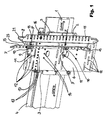
- Fig. 1 depicts the device according to the invention in a position in which the driven door that is associated with this device is connected to the non-driven door in order to entrain the latter in the opening or closing direction.
- the device according to the invention is used for actuating sliding doors.
- the sliding doors can each be composed of one or more door panels that travel in series and can "telescope,” so to speak, in order to open, which will not be described in greater detail below.
- the drawing here clearly shows the guide rail 1, which is as a rule mounted at the top of a car so that it extends essentially in the horizontal direction.
- At least one carriage 2 travels along the guide rail 1 and for this purpose, is equipped with rollers 3 on which the carriage travels along the guide rail 1.
- rollers 3 are provided on the underside, but are not shown here. These prevent the carriage from derailing or coming unhooked.
- the necessary movement is provided by a linear drive unit, which is preferably a cable or drive belt 4 and which travels over a drive roller and a corresponding counterpart roller, neither of which is shown here.
- the so-called opening direction is the movement direction of the drive belt 4, which is indicated by the arrow marked OPEN.
- the so-called closing direction is indicated by the arrow marked CLOSE.
- the entraining skid support 6 is fastened directly to the drive belt 4, most often without the interposition of a loose element such as a spring or a damper.
- the entraining skid support 6 is preferably an at least essentially flat plate made of sheet metal. Ideally, it has a thickness of at least 1 mm.
- the entraining skid support 6 in turn supports a first entraining skid 7 and a second entraining skid 8.
- the first entraining skid 7 of the exemplary embodiment shown here is a mobile entraining skid.
- This mobile entraining skid is distinguished by the fact that it is secured to the entraining skid support 6 by means of at least two pivoting levers 9 in a way that allows it to move relative to the entraining skid support.
- each of the pivoting levers 9 is fastened to the entraining skid 7 in rotary fashion by means of a first bearing 10 and is secured to the entraining skid support 6 in rotary fashion by means of a second bearing 11.
- each of the two above-mentioned bearings includes a bearing pin, which has a thread at its one end, by means of which it can be firmly screwed to the entraining skid support 6 and/or to the entraining skid 7.
- the second entraining skid 8 of the exemplary embodiment shown here is an immobile entraining skid. This means that this entraining skid 8 is fastened and preferably screwed to the entraining skid support 6 so that it cannot move relative to the latter.
- the entraining skid support 6 is provided with a plurality of first openings 12, in this case, 9 each in its upper section and lower section.
- these first openings 12 constitute a field composed of a plurality of holes, ideally in the form of oblong holes, preferably situated one after another in the movement direction of the entraining skid support and a plurality thereof arranged next to each other transversely to this movement direction.
- at least three oblong holes are situated one after another per row and at least three rows of oblong holes are situated next to one another.
- Each of the oblong holes is preferably longer than the width of the two entraining skid supports.
- the oblong holes of adjacent rows are offset relative to one another, which increases the flexibility and stability of the entraining skid support.
- first openings 12 permit the two entraining skids 7 and 8 to be fastened to the entraining skid support 6 in a wide variety of positions.
- at least two of the oblong holes are provided with retaining screws by means of which the immobile entraining skid 8 is clamped to the entraining skid support 6 so that it is mounted there in stationary fashion.
- at least two additional bearing pins are provided, which can preferably be screw-mounted into the oblong holes; they each constitute a swivel bearing for a respective second bearing 11 of the pivoting lever 9 and simultaneously keep the relevant bearing eye in position.
- the entraining skid support is typically at least 20 cm wide and at least 35 cm high, it is then clear that with the aid of the first openings 12, it is possible to vary the functional position of the entraining skids 7 and 8 by at least 7.5 cm in the vertical direction transverse to the movement direction and by at least 15 cm along the movement direction of the door without having to change the position of the entraining skid support 6 as such or having to produce additional holes in the entraining skid support 6 on the job site.
- each of the entraining skids is also provided with a large number of holes 15 (preferably between 12 and 24 of them). Only some of these holes 15 are needed in order to fasten the relevant entraining skid to the entraining skid support 6. Most often, only 2 are used for this purpose.
- these holes 15 are preferably embodied in the form of oblong holes, which extend at least essentially in the direction parallel to the movement direction.
- these holes are preferably embodied in the form of circular holes, each of which can have another bearing pin fastened or screwed to it, which belongs to a first bearing 10 that serves to fasten the pivoting levers to the relevant entraining skid 7 in pivoting fashion.
- the embodiment of the holes 15 in the form of oblong holes in the entraining skid that is immobile relative to the entraining skid support significantly facilitates the adjustment and elimination of the coupling play, which will be described in greater detail below.
- the entraining skid support 6 is preferably provided with a plurality of second openings 13. These make it possible to fasten the linear drive unit or in the present case, its drive belt 4, to different positions on the entraining skid support 6. This also increases the installation flexibility.
- the entraining skid support 6 has various third openings 14, which make it possible to connect it to the carriage 2 in various positions.
- the drive unit for the active actuation of the at least one entraining skid is embodied so that it does not absolutely force the entraining skid and entraining skid support 6, which are driven by it, to assume a particular position. Instead, the drive unit is embodied so that it is largely independent of the position in which the entraining skid that is driven by it is mounted on the entraining skid support 6 and of the position in which the entraining skid support 6 is associated with the carriage 2.
- Fig. 1 shows a snapshot in which the carriage 2 of the door panel and the entraining skid support 6 are affixed to each other. They move in tandem in the closing direction, in the direction of the arrow marked CLOSE.
- the door panel associated with the carriage 2 is fastened in the vicinity of the lower section of the carriage 2. It hangs downward from there.
- the door panel is not shown in Fig. 1 for the sake of better visibility.
- the carriage 2 and the entraining skid support 6 are immobilized relative to each other by means of the securing coupling 17.
- This securing coupling 17 is preferably a magnetic clamp.
- This coupling is fastened to one of the two above-mentioned components and magnetically attracts the other component.
- an electromagnet here or another holding means such as a snap-lock coupling, which can only be disengaged by overcoming the specified holding forces.
- the two entraining skids 7 and 8 are in their driving position. In the driving position, they generally rest without play against the coupling elements of a door (usually a shaft door) that is to be entrained by them.
- the entraining skids are preferably positioned on the entraining skid support 6 so that in this movement phase, the pivoting levers 9 - due to the reaction forces, which act on the entraining skid 7 and tend to push it in the opening direction - are not or essentially are not acted on by a torque acting in the opening direction.
- the two resultants of these reaction forces are each indicated by means of an arrow F in Fig. 1 .
- the decisive factor in this exemplary embodiment is that the entraining skid 7 is positioned so that the central axes of its two bearings 10 and 11 essentially lie on the same line, which is oriented parallel to the movement direction. In this way, the reaction forces, which are each symbolized by an arrow F, extend through the center points of the two bearings and in this way, do not exert torque on the pivoting lever 9.
- At least one spring is provided, which elastically prestresses the entraining skid support toward its driving position.
- This spring is not visible in Fig. 1 because it is preferably situated and suspended on the back side of the entraining skid support.
- a part of the door contact 16 is positioned on the entraining skid that is situated directly on the side of the door gap. The purpose of this is to provide information at all times regarding whether the door is completely closed or is completely or partially open.
- the actuating element 20 is almost invisible in Fig. 1 .
- the only part of the actuating element 20 that is visible here is a small part of the actuating section 21 and the roller 25, which is fastened to the entraining skid 7 (with the aid of a bearing pin that preferably has a thread at one end).
- This roller is provided to interact with the actuating element 20 and with its actuating section 21.
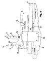
- the arrow S1 shown in Fig. 2 symbolizes the viewing direction of the observer when looking at Fig. 4 , which is associated with Fig. 1 .
- Fig. 4 clearly shows the actuating element 20, which is used to couple and uncouple the entraining skids 7, 8.
- the actuating element 20 is composed of an actuating section 21 and a holding section 22 that is preferably screwed to it.
- the actuating section 21 is connected to the holding section 22 with the aid of one or more different holes, ideally one or more oblong holes, as shown here.
- the holding section 22 is in turn generally connected to the guide rail 1 in an immobile fashion, which is symbolized in Fig. 4 by the two screw ends that are not depicted in greater detail. In principle, it is possible to provide oblong holes here as well in order to be able to adjust the position of the holding section.
- Fig. 4 also shows the drive belt 4 and the back side of both the entraining skid support 6 and the entraining skids 7 and 8.
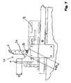
- the different functional sections of the actuating section 21 can be seen by taking a quick look at Fig. 7 .
- the actuating section 21 has a section that can be referred to as the "wedge" 24, which transitions by means of a rounded section 26 into a section that can be referred to as the "stopper" 23.
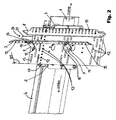
- Fig. 2 shows a snapshot at a point in time after the one shown in Fig. 1 .
- the mobile entraining skid 7 has already been lifted a fair distance up by the wedge 24 and has as a result simultaneously slid relative to the entraining skid support 6 in the direction of the OPEN arrow. Consequently, at the moment shown in Fig. 2 , the entraining skid 7 begins to disengage from the coupling elements of the shaft door that has been entrained up to this point. At this time, the shaft door and the entrained door have just reached their completely closed position.
- Fig. 3 shows a snapshot at a point in time even later than the one shown in Fig. 2 .
- the entraining skid support 6 has simultaneously moved even further in the closing direction past the actuating element 20 and its actuating section 21. But since the stopper 23 of the actuating section 21 has prevented any further movement of the entraining skid 7 in the closing direction (see Fig. 6 ), the entraining skid 7 has therefore been pivoted into its completely open position. The coupling sections of the door to be entrained have thus been completely released and are no longer connected to the entraining skids 7 and 8. The car can then begin its trip.
- the actuating section 21 is preferably connected by means of one or more holes or oblong holes to its holding section 22, which is in turn firmly fixed or possibly even screwed to the guide rail 1 by means of one or more oblong holes.
- This plurality of holes or oblong holes makes it possible to fix the actuating section 21 in different positions. Because of this (unlike in the prior art), the actuating element 20 also does not absolutely force the entraining skids 7, 8 and/or the entraining skid support 6 to assume a particular position. It is therefore largely unnecessary to take the actuating element 20 and its position into consideration.
- the various holes and oblong holes can be used to install the entraining skid supports 6 and the entraining skids 7 in the position that is required in order to adapt the device to the circumstances that occur due to the modernization. Only then is it necessary to attend to the actuating element 20 and install it in a position that ensures a proper operation.
- the mobile entraining skid does not absolutely have to be guided on pivoting levers 9. It is also alternatively conceivable here to support the mobile entraining skid 7 in mobile fashion on the entraining skid support 6 by virtue of the fact that the mobile entraining skid 7 has slots in which fixed bearing pins travel. Details about what such a slot-guided bearing can look like can be inferred from the previously published European patent application EP 2 287 104 , which is incorporated in its entirety into the present description by reference.
- actuating element 20 can likewise be embodied in a way that is entirely different from the example described above. It is thus easily possible to embody the actuating element 20 as a control cable that is actuated by the carriage 2, for example at the moment in which it separates from the entraining skid support and begins to move relative to it.
- Fig. 8 shows the simplest case of such an alternative design.
- One of the pivoting levers 9 in this case is L-shaped, i.e. is embodied in the form of an elbow lever.
- a steel cable STAS is connected to the lever arm oriented away from the entraining skid 7.
- the other end of the steel cable is connected, for example, to a link LAS that is provided for this purpose on carriage 2.
- the entraining skid support moves relative to the carriage, see ⁇ 1 and ⁇ 2.
- the resulting tautening of the steel cable STAS which has been selected to be of an appropriate length, produces a cable force that acts on the above-mentioned other end of the elbow lever and as a result, in any case produces a torque that lifts the entraining skid.
- Fig. 14 discloses another variant of this first exemplary embodiment.
- the variant shown in Fig. 14 deviates from the one described first in that the immobile entraining skid is no longer situated toward the front viewed in the closing direction, but instead toward the back.
- the mobile entraining skid and the immobile entraining skid have therefore switched places, so to speak.
- the mobile entraining skid 7 is actuated in exactly the same way as previously described: it comes into contact with an actuating element 20 of the kind that has already been described above, which is stationary, but can as a rule be mounted in different positions.
- the positioning variability of the entraining skids is present here in exactly the same way as described above for the first variant.
- the extraordinary positioning variability that is the subject of the invention makes it possible for all of the essential components (in particular the entraining skid support, the entraining skids, and the actuating element as well as preferably also the pivoting levers) to be embodied so that without any change in their physical properties and purely by means of a different assembly, they can be embodied so as to produce the device shown in Figs. 1 through 3 as a finished product and also so that they produce the device shown in Fig. 14 as a finished product.
- the second exemplary embodiment of the invention is distinguished by the fact that in addition, a locking of the car door is provided and that the immobile entraining skid 8 that is preferred in the first exemplary embodiment is now made mobile and thus becomes the second mobile entraining skid 8a, which in turn acts directly on the car door bolt and in so doing, controls the raising and lowering thereof.
- the first and second exemplary embodiment are structurally identical so that the descriptions given for the first exemplary embodiment also apply to the second exemplary embodiment, provided that nothing to the contrary is dictated by the above-mentioned difference.
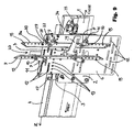
- Fig. 9 is the counterpart to Fig. 1 and shows the second exemplary embodiment in a position in which the driven door that is associated with this device is connected to the non-driven door in order to entrain the latter in the opening or closing direction.
- the entraining skid support 6 supports a first entraining skid 7 and a second entraining skid 8a.
- the first entraining skid 7 is embodied in exactly the same way as described for the first exemplary embodiment and it is also moved by an actuating element 20 from its raised position into its closed position and vice versa in exactly the same way.
- the second entraining skid 8a is also embodied as a mobile entraining skid.
- the second entraining skid 8a is also secured to the entraining skid support 6 by means of at least two pivoting levers 9 in a way that allows it to move relative to this entraining skid support.
- each of the pivoting levers 9 is fastened to the entraining skid 7 in rotary fashion by means of a first bearing 10 and is secured to the entraining skid support 6 in rotary fashion by means of a second bearing 11.
- each of the two above-mentioned bearings 10, 11 has a bearing pin that has a thread at its one end, by means of which it can be securely screwed to the entraining skid support 6 and to the entraining skid 7, preferably in different positions of one and the same oblong hole of the entraining skid support 6 or in different holes of the various ones that are provided for this purpose in the entraining skid support so that the second entraining skid 8a can be fastened to the entraining skid support 6 in exactly the same variable fashion relative to the latter as described above for the first entraining skid 7.
- the mechanism for actuating the car door bolt utilizes the relative movement between the entraining skids 7, 8a and preferably the relative movement of the second entraining skid 8a and the entraining skid support in order to actuate a slider 30, which in turn provides for the lifting and continued sliding of the car door bolt.
- the significant advantage that can be achieved as needed with such a slider 30 is that the slider 30 can be actuated from very different positions, which is why it also does not require any particular position in which the entraining skids must be mounted on the entraining skid support. Despite the additional car locking, the device therefore retains its extraordinarily wide range of adjustability.
- the contact element 27 preferably rests against the flank of the entraining skid 8a oriented away from the coupler rollers 36 of the shaft door and is acted on by it with a compressive force at the appropriate time.
- the contact element 27 is embodied as a roller 28, which rotates on an axle 29.
- the contact element 27 or the axle 29 that constitutes a part of the contact element 27 reaches through an oblong hole provided for this purpose, which is ideally one of the openings 12 for fastening the entraining skids 7, 8a, and through the entraining skid support 6 and on the back side of the entraining skid support 6 oriented away from the entraining skids, is connected to the actuating mechanism that is mounted there for the car door bolt 34.
- FIG. 12 shows the entraining skid support 6 from behind, i.e. viewed from its side oriented away from the entraining skids 7, 8a.
- the drawing here clearly shows the lock support 37, on which the entraining skid support 6 is supported in a transversally sliding fashion by means of rollers 38.
- the lock support 37 is an integrally or permanently installed component of the carriage that is not shown per se in Fig. 12.
- Fig. 12 does, however, show the two holes provided approximately in the center of the lock support 37 for mounting the lock support 37 to the carriage with screws.
- the core of the actuating mechanism is the slider 30.
- the slider 30 has at least one oblong hole 31, which preferably extends over more than half and better still more than 2/3 of the length of the slider 30 measured parallel to its movement direction.
- the slider has a plurality of such oblong holes arranged in parallel and next to one another, as shown in this exemplary embodiment, so that the bolt can be fastened to the slider in different positions in both the vertical and horizontal directions.
- the axle 29 mentioned above is affixed in the at least one oblong hole of the slider 30.
- the slider that is used to actuate the car door bolt does not require any particular position of the entraining skids on the entraining skid support.
- the entraining skids as has already been described in connection with the first exemplary embodiment, particularly through the use of the openings 12 and the holes 15, can be fastened to the entraining skid support 6 in exactly the position that it must assume in order to be able to correctly cooperate with the shaft doors of the existing system.
- the contact element 27 or its axle 29 is inserted into the relevant at least one oblong hole 31 and fastened there so that the entraining skid 8a can actuate the contact element 27.
- Fig. 12 also clearly shows a reversing mechanism 32 that is supported on the entraining skid support 6 in pivoting fashion and in this specific instance, is embodied in the form of a rocker.
- the reversing mechanism 32 is connected in rotary fashion to a control rod 33 on the one hand, which lifts the car door bolt 34 or allows it to fall, and on the other hand, is connected in rotary fashion to the slider 30.
- the reversing mechanism thus constitutes one of the two retaining bearings of the slider 30.
- the other retaining bearing of the slider is likewise shown in Fig. 12 : it can be a corresponding extension of the bearing 11 of the pivoting lever, which is involved in supporting and guiding the first entraining skid 7.
- a component of this bearing can be a pin end that protrudes freely beyond the back side of the entraining skid support and protrudes through the oblong hole 31 of the slider 30 and guides it, usually together with a correspondingly embodied nut.
- the slider 30 is thus preferably supported so that it is able to move in a predominantly translatory fashion in the direction of the opening and closing movement of the door panels (see the indicating arrows in Fig. 12 ) and only executes a negligible pivoting movement due to being attached at one end to the reversing mechanism 32 or the rocker that constitutes it.
- Fig. 9 shows a snapshot in which the shaft door and naturally along with it, the car door as well (both not graphically depicted per se) are still completely closed. In this case, the car door is not only closed, but also locked because the car door bolt 34 is still in its latch 35.
- the entraining skid 8a has a stop 40 with which in its position shown in Fig. 9 , it rests - preferably against the upper side edge of the entraining skid support 6 -, in order not to sag downward.
- the drive unit that is responsible for the opening of the doors nevertheless begins to move and thus produces a tensile force Z acting on the drive belt 4 in the opening direction. Since the drive belt 4 is affixed to the entraining skid support 6, it forcibly imparts a movement in the direction of the arrow Z to the entraining skid support 6, which the latter can execute despite the fact that at this stage, the door panels still remain in the closed position, since it is supported in sliding fashion relative to the relevant carriage 2 and the lock support that is as a rule rigidly connected to the latter.
- the respective second bearings 11 of the two pivoting levers 9 move together with it in the direction of the arrow Z.
- the second entraining skid 8a then comes into contact with the coupler rollers 36 of the shaft door that is still kept locked with the aid of the shaft door bolt 39; the entraining skid support 6, in the course of its further movement, cannot at first follow further in the direction of the arrow Z, but instead moves in relation to it in the direction opposite from the direction of the arrow Z. Since the second entraining skid 8a rests - preferably with its side oriented away from the coupler rollers 36 - against the contact element 27, which is composed of the roller 28 and the axle 29 that is affixed to the slider 30, it transmits its relative movement to the slider 30. The slider 30 thus likewise moves relative to the entraining skid support 6 in the direction opposite from the direction of the arrow Z.
- the slider thus pivots the reversing mechanism or rocker 32, which consequently pulls the control rod 33, whose other end is connected to the car door bolt 34.
- the control rod 33 pulls the car door bolt 34 out of its latch 35, thus unlocking the car door.
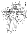
- the second entraining skid 8a exerts a compressive force on its associated coupler roller 36 of the shaft door so that the shaft door bolt is unlocked, thus producing the position that is shown in Fig. 10 .
- Fig. 10 clearly shows that the contact element or the roller 25 of the entraining skid 7 is still interacting with the actuating element, mostly in that it is still resting against the section of the actuating element 20 referred to as the "stopper" (in this regard, see Fig. 7 ).
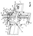
- the contact element or its roller 25 lowers relative to the actuating element 20 so that the first entraining skid reaches its closed position, as shown in Fig. 11 .
- the first and second entraining skids 7, 8a securely hold the coupler rollers 36 of the shaft door between themselves and thus entrain the shaft door, as a rule without play or rattling.
- the first entraining skid 7, together with its pivoting levers 9, is advantageously positioned on the entraining skid support in such a way that the pivoting levers are fully extended or at least essentially extended so that the reaction forces that are acting on the entraining skid 7 and tend to push it in the opening direction are not or are essentially not subjected to a torque that acts in the opening direction.
- the second entraining skid 8a also does not absolutely have to be guided on pivoting levers 9.
- the actuating element 20 can likewise be embodied in a way that is entirely different from the example described above. It is thus easily possible for the actuating element 20 to be embodied as a control cable that is actuated by the carriage 2, for example at the moment in which it separates from the entraining skid support and begins to move relative to it.
- An actuating element that is embodied in this way basically corresponds to the one shown in Fig. 8 , as an alternative design in conjunction with the first exemplary embodiment.
- Fig. 13 shows an exemplary embodiment that largely corresponds to the exemplary embodiment described above in conjunction with Figs. 9 through 12 - with the difference that the car door bolt 34 does not drop into its latch 35 from above, as shown in Fig. 12 , but is pulled into its latch from below.
- Fig. 13 clearly shows the slider 30, the lock support 37 - which is supported on rollers 38 so that it is able to move in translatory fashion relative to the entraining skid support 6 and which is a component of the carriage, and the reversing mechanism 32 - which is embodied here as a rocker.
- the figure also clearly shows the first and second openings 12, 13, which ensure the high degree of variability of the system, as well as the at least one oblong hole 31 provided for this same purpose in the slider 30 and the axle 29 of the actuating element 27 that is fastened in a suitable position therein.
- a device for synchronously actuating and locking elevator doors which are situated essentially one behind the other in the passage direction - such as a car door and a shaft door; the device includes entraining skids 7, 8 that are fastened to a first door by means of an entraining skid support and whose spacing relative to one another can be changed in order to be able to couple the first door to the second door and move them together.
- the device is coupled to a linear drive unit that moves one of the doors in the opening and closing directions. Since the entraining skid support 6 has a plurality of first openings 12, it is possible to mount at least one, preferably both entraining skids on the entraining skid support 6 in a wide variety of functional positions.
- protection is also claimed for a device that is distinguished by the fact that the first openings 12 form a field or matrix, which makes it possible to mount one, preferably both entraining skids 7, 8 on the entraining skid support 6 in a wide variety of functional positions in both the vertical and horizontal direction.
- protection is also claimed for a device that is distinguished by the fact that at least two - and preferably all - of the first openings 12 in the entraining skid support 6 are oblong holes, regardless of the presence of other openings for other purposes.
- protection is also claimed for a device that is distinguished by the fact that at least two - and preferably all - of the first openings 12 are oblong holes whose length exceeds the maximum width of at least one or better still, both entraining skids 7, 8 transverse to the movement direction of the carriage 2.
- protection is also claimed for a device that is distinguished by the fact that the entraining skid support 6 has a plurality of second openings 13 that make it possible to connect the entraining skid support 6 to a mobile element of the linear drive unit in different ways.
- protection is also claimed for a device that is distinguished by the fact that the entraining skid support 6 has a plurality of third openings 14, which make it possible to fasten a carriage 2 of a door panel to it in different positions, preferably in such a way that the entraining skid support 6 is held so that it is able to move relative to the carriage 2 by a particular amount.
- protection is also claimed for a device that is distinguished by the fact that an entraining skid 8 is mounted on the entraining skid support 6 in a functional position in which the entraining skid 8 is immobilized relative to the entraining skid support 6.
- the immobilized entraining skid 8 has a plurality of holes 15, preferably in the form of oblong holes, which are positioned and matched to the openings 12 in the entraining skid support 6 so that by means of these holes 15, the entraining skid 8 can be fastened to the entraining skid support 6 in different positions relative to it; preferably at least four, or better still at least eight of the above-mentioned holes 15 are provided; the holes 15 preferably serve to fasten a door contact switch or a part of it to the entraining skid 8 in different positions.
- protection is also claimed for a device that is distinguished by the fact that one and preferably only one entraining skid 7 is mounted on the entraining skid support 6 in a functional position in which the entraining skid 7 is mobile relative to the entraining skid support 6.
- each of the pivoting levers 9 has a first mobile bearing 10 with a first axle that connects it to the entraining skid 7 and a second mobile bearing 11 with a second axle that connects it to the entraining skid support 6; and the second axles can be affixed to the entraining skid support 6 in different functional positions by means of first openings 12 in the latter.
- the at least one mobile entraining skid 7 likewise has a plurality of holes 15, which are positioned and matched to the openings 12 in the entraining skid support 6 so that by means of these holes 15, the entraining skid 7 can be affixed in different positions relative to the entraining skid support 6; preferably, at least four, or better still at least eight of the above-mentioned holes 15 are provided; and preferably, the holes 15 simultaneously serve to permit a driving element or a driving roller 25 to be fastened in different positions in order to interact with an actuating element 20.
- protection is also claimed for a device that is distinguished by the fact that one of the entraining skids 7, 8 simultaneously serves as a contact support for at least a part of the contact that indicates that the door is situated in its completely closed position.
- protection is also claimed for a device that is distinguished by the fact that the device includes an actuating element 20 that couples and uncouples the entraining skids 7, 8 to and from the door that is to be entrained and in so doing, interacts with at least one entraining skid 7 so that the actuating element 20 does not place any absolute requirements on the positioning of the entraining skids 7, 8 on the entraining skid support 6, but permits utilization of all of the mounting positions that are made possible by the different openings of the entraining skid support 6 that are to be used alternatively.
- protection is claimed for a device that is distinguished by the fact that the entraining skid that controls the opening and closing movement moves a slider 30 that is able to move in a completely or at least predominantly translatory fashion and that is in turn coupled to the car door bolt 34.
- protection is also claimed for a device that is distinguished by the fact that the slider that is able to move in an at least essentially translatory fashion is supported on the side of the entraining skid support oriented away from the entraining skids.
- protection is also claimed for a device that is distinguished by the fact that the slider is associated with a contact element 27, which is preferably comprised of a pin 29 that can be fastened to the slider 30 in different positions and preferably supports a roller 28, and the contact element 27 ideally protrudes through an opening 12 of the entraining skid support 6 into the region of the side of the entraining skid support 6 on which the entraining skids 7, 8a are situated.
- a contact element 27 is preferably comprised of a pin 29 that can be fastened to the slider 30 in different positions and preferably supports a roller 28, and the contact element 27 ideally protrudes through an opening 12 of the entraining skid support 6 into the region of the side of the entraining skid support 6 on which the entraining skids 7, 8a are situated.
- protection is also claimed for a device that is distinguished by the fact that the slider 30 has a plurality of holes generally situated one after another in a row and/or at least one oblong hole 31, preferably a plurality of them, that are suitable for fastening the pin in different positions.
- protection is also claimed for a device that is distinguished by the fact that the slider has a plurality of rows of holes situated next to one another with reference to its sliding direction and/or a plurality of oblong holes that at least in some sections, are situated next to one another with reference to its sliding direction.
- protection is also claimed for a device that is distinguished by the fact that the entraining skid 8a that controls the opening and closing movement is not firmly coupled to the contact element 27, but is embodied so that only compressive forces can be transmitted between the entraining skid 8a and the contact element 27.
- an entraining skid support 6 is fastened to a carriage 2; previously or subsequently, entraining skids 7, 8 are fastened to the entraining skid support 6 by means of alternatively provided openings 12 in a position in which they can properly couple to and uncouple from coupling sections of a door that is to be entrained; and preferably next, the position of an actuating element 20 relative to the entraining skid support 6 is set to the current position of at least one of the entraining skids 7 so that the actuating element lifts and closes the at least one entraining skid 7 as the entraining skid support 6 is being moved by the linear drive unit, in order to uncouple or couple it.
- an entraining skid support 6 is fastened to a carriage 2; previously or subsequently, entraining skids 7, 8 are fastened to the entraining skid support 6 by means of alternatively provided openings 12 in a position in which they can properly couple to and uncouple from coupling sections of a door that is to be entrained; and preferably next, the position of an actuating element 20 relative to the entraining skid support 6 is set to the current position of at least one of the entraining skids 7 so that the actuating element lifts and closes the at least one entraining skid 7 as the entraining skid support 6 is being moved by the linear drive unit, in order to uncouple or couple it; preferably, oblong holes in an immobile entraining skid are used - after the positioning of a mobile entraining skid and the adjustment of preadjustment of its cooperation
- Last but not least, use protection is also claimed, particularly for the use of an obstacle, which can be affixed in a changeable position, ideally by means of one or more oblong holes and/or alternative fastening holes and/or a rail-like press fit, with which the at least one entraining skid comes into contact in order to thus be lifted, ideally in combination with the use of an entraining skid support 6, preferably in the form an essentially flat plate, which is provided with a plurality of alternatively used first and/or second and/or third openings 12, 13, 14, which are prefabricated, preferably punched, in series for the installation of the entraining skids 7, 8 in different functional positions, preferably for modernizing the door drive unit of differently embodied existing elevator systems.
- the device additionally differs from the known state of the art that the entraining skid 8a that controls the opening and closing movement is not firmly coupled to the contact element 27, but is embodied so that only compressive forces can be transmitted between the entraining skid 8a and the contact element 27.
- the device additionally differs from the known state of the art that the entraining skids 7, 8, 8a are held by an entraining skid support 6, which has a plurality of first openings 12 that make it possible to mount at least one, preferably both entraining skids 7, 8, 8a) on the entraining skid support 6 in different functional positions; the entraining skid support 6 preferably also has second and ideally even additional third openings and in the optimal case, the entraining skids 7, 8, 8a each have a plurality of holes 15 that are alternatively suitable for fastening in different positions.
Landscapes
- Engineering & Computer Science (AREA)
- Mechanical Engineering (AREA)
- Automation & Control Theory (AREA)
- Elevator Door Apparatuses (AREA)
- Power-Operated Mechanisms For Wings (AREA)
Applications Claiming Priority (2)
| Application Number | Priority Date | Filing Date | Title |
|---|---|---|---|
| DE202014102230 | 2014-05-13 | ||
| DE202014102533.2U DE202014102533U1 (de) | 2014-05-13 | 2014-05-28 | Türkuppler mit einer ihre flexible Positionierung ermöglichenden Betätigung |
Publications (3)
| Publication Number | Publication Date |
|---|---|
| EP2944597A2 true EP2944597A2 (fr) | 2015-11-18 |
| EP2944597A3 EP2944597A3 (fr) | 2016-03-09 |
| EP2944597B1 EP2944597B1 (fr) | 2024-07-03 |
Family
ID=54193516
Family Applications (1)
| Application Number | Title | Priority Date | Filing Date |
|---|---|---|---|
| EP15167356.3A Active EP2944597B1 (fr) | 2014-05-13 | 2015-05-12 | Coupleur de porte avec un actionnement qui lui permet d'être positionné de manière flexible |
Country Status (5)
| Country | Link |
|---|---|
| US (1) | US9637350B2 (fr) |
| EP (1) | EP2944597B1 (fr) |
| DE (1) | DE202014102533U1 (fr) |
| ES (1) | ES2986333T3 (fr) |
| HU (1) | HUE067918T2 (fr) |
Cited By (1)
| Publication number | Priority date | Publication date | Assignee | Title |
|---|---|---|---|---|
| DE102019204321A1 (de) * | 2019-03-28 | 2020-10-01 | Franz Xaver Meiller Fahrzeug- Und Maschinenfabrik - Gmbh & Co Kg | Variables Mitnehmersystem |
Families Citing this family (15)
| Publication number | Priority date | Publication date | Assignee | Title |
|---|---|---|---|---|
| CN106414302A (zh) * | 2014-03-19 | 2017-02-15 | 威特控股有限公司 | 用于提升门的阻挡系统和组件 |
| DE202014102534U1 (de) * | 2014-05-13 | 2015-08-18 | Wittur Holding Gmbh | Türkuppler mit flexibel positionierbaren Kupplerkufen |
| JP6250190B2 (ja) * | 2014-10-15 | 2017-12-20 | 三菱電機株式会社 | エレベータのかごドア装置 |
| ES2968008T3 (es) * | 2015-08-04 | 2024-05-06 | Otis Elevator Co | Enclavamiento de puerta de cabina con bloqueo de umbral |
| KR102561201B1 (ko) * | 2015-08-04 | 2023-07-28 | 오티스 엘리베이터 컴파니 | 엘리베이터 카 도어 인터로크 |
| CN109720972B (zh) * | 2017-10-27 | 2020-05-01 | 上海三菱电梯有限公司 | 电梯轿厢门机装置 |
| US11040858B2 (en) | 2018-05-01 | 2021-06-22 | Otis Elevator Company | Elevator door interlock assembly |
| US11155444B2 (en) * | 2018-05-01 | 2021-10-26 | Otis Elevator Company | Elevator door interlock assembly |
| US11040852B2 (en) | 2018-05-01 | 2021-06-22 | Otis Elevator Company | Elevator car control to address abnormal passenger behavior |
| US11046557B2 (en) | 2018-05-01 | 2021-06-29 | Otis Elevator Company | Elevator door interlock assembly |
| US11034548B2 (en) | 2018-05-01 | 2021-06-15 | Otis Elevator Company | Elevator door interlock assembly |
| EP3566995B1 (fr) | 2018-05-09 | 2021-06-30 | Otis Elevator Company | Système de couplage de porte de cabine d'ascenseur |
| CN114030971B (zh) * | 2021-10-26 | 2023-06-13 | 宁波欣达电梯配件厂 | 一种同步门刀装置 |
| US11760604B1 (en) | 2022-05-27 | 2023-09-19 | Otis Elevator Company | Versatile elevator door interlock assembly |
| CN118047289A (zh) | 2022-11-10 | 2024-05-17 | 奥的斯电梯公司 | 电梯轿门锁装置和电梯设备 |
Citations (2)
| Publication number | Priority date | Publication date | Assignee | Title |
|---|---|---|---|---|
| WO2005077808A2 (fr) | 2004-02-11 | 2005-08-25 | Wittur Gmbh | Dispositif d'actionnement et de verrouillage de portes d'ascenseurs |
| EP2287104A1 (fr) | 2009-08-21 | 2011-02-23 | Wittur Holding GmbH | Coupleur de porte et mécanisme de verrouillage |
Family Cites Families (21)
| Publication number | Priority date | Publication date | Assignee | Title |
|---|---|---|---|---|
| JPS6298678A (ja) | 1985-10-25 | 1987-05-08 | Hitachi Ltd | 太陽電池用基板の製造方法 |
| JPS6298678U (fr) * | 1985-12-09 | 1987-06-23 | ||
| ATE75458T1 (de) * | 1988-03-18 | 1992-05-15 | Inventio Ag | Tuerantriebsvorrichtung mit verriegelungsmechanismus fuer aufzuege. |
| EP0679602A1 (fr) * | 1994-04-25 | 1995-11-02 | Inventio Ag | Dispositif d'entraînement pour portes d'ascenseur |
| FR2725190B1 (fr) * | 1994-09-29 | 1996-11-15 | Otis Elevator Co | Dispositif de liaison d'une porte de cabine d'ascenseur et d'une porte de palier pour leur ouverture et fermeture synchrones |
| FI101284B1 (fi) * | 1995-09-13 | 1998-05-29 | Kone Oy | Järjestely hissin automaattiovien avaamisessa ja sulkemisessa ja mukaanottaja |
| FI101784B (fi) * | 1995-09-13 | 1998-08-31 | Kone Corp | Menetelmä hissin tasonoven liikuttamiseksi ja mukaanottaja |
| US5819877A (en) * | 1996-04-10 | 1998-10-13 | Otis Elevator Company | Elevator evacuation deterrent device |
| EP0829446A1 (fr) * | 1996-09-12 | 1998-03-18 | Inventio Ag | Dispositif d'entraînement pour portes d'ascenseur |
| ATE250551T1 (de) * | 1996-10-29 | 2003-10-15 | Inventio Ag | Vorrichtung zum öffnen und schliessen einer kabinentür und einer schachttür einer aufzugsanlage |
| KR100303010B1 (ko) * | 1998-12-07 | 2002-05-09 | 장병우 | 엘리베이터클러치장치 |
| US6446759B1 (en) * | 2001-06-08 | 2002-09-10 | Otis Elevator Company | Door coupler and latch system for elevator car and landing doors |
| ITMI20042249A1 (it) * | 2004-11-19 | 2005-02-19 | Sematic Italia Spa | Scivolo attivo per porte di cabina di ascensori |
| EP1820766A1 (fr) * | 2006-02-21 | 2007-08-22 | Inventio Ag | Méthode pour la modernisation d'un système de porte de cabine |
| CN102686499B (zh) * | 2009-10-09 | 2014-05-21 | 三菱电机株式会社 | 电梯的门卡合装置 |
| JP5804695B2 (ja) * | 2010-11-30 | 2015-11-04 | 東芝エレベータ株式会社 | エレベータのかご振動抑制装置 |
| KR101074859B1 (ko) * | 2011-04-19 | 2011-10-19 | (주)에이엔티 | 카도어 잠금장치를 포함한 도어벤 |
| CN103562117B (zh) * | 2011-05-31 | 2015-05-27 | 因温特奥股份公司 | 可变轿厢门/竖井门联结器 |
| US9663329B2 (en) * | 2012-06-18 | 2017-05-30 | Sematic S.P.A. | Lift cages with improved blocking/releasing devices |
| ES2558355T3 (es) * | 2012-08-10 | 2016-02-03 | Wittur Holding Gmbh | Acoplador de puerta con descarga del elemento de bloqueo de puerta de caja |
| CN103723605B (zh) * | 2013-09-23 | 2015-08-26 | 西子奥的斯电梯有限公司 | 一种电梯集成轿门锁的异步门刀 |
-
2014
- 2014-05-28 DE DE202014102533.2U patent/DE202014102533U1/de not_active Expired - Lifetime
-
2015
- 2015-05-12 HU HUE15167356A patent/HUE067918T2/hu unknown
- 2015-05-12 ES ES15167356T patent/ES2986333T3/es active Active
- 2015-05-12 EP EP15167356.3A patent/EP2944597B1/fr active Active
- 2015-05-13 US US14/711,299 patent/US9637350B2/en active Active
Patent Citations (2)
| Publication number | Priority date | Publication date | Assignee | Title |
|---|---|---|---|---|
| WO2005077808A2 (fr) | 2004-02-11 | 2005-08-25 | Wittur Gmbh | Dispositif d'actionnement et de verrouillage de portes d'ascenseurs |
| EP2287104A1 (fr) | 2009-08-21 | 2011-02-23 | Wittur Holding GmbH | Coupleur de porte et mécanisme de verrouillage |
Cited By (2)
| Publication number | Priority date | Publication date | Assignee | Title |
|---|---|---|---|---|
| DE102019204321A1 (de) * | 2019-03-28 | 2020-10-01 | Franz Xaver Meiller Fahrzeug- Und Maschinenfabrik - Gmbh & Co Kg | Variables Mitnehmersystem |
| WO2020193088A1 (fr) | 2019-03-28 | 2020-10-01 | Franz Xaver Meiller Fahrzeug- Und Maschinenfabrik - Gmbh & Co Kg | Système d'entraînement variable |
Also Published As
| Publication number | Publication date |
|---|---|
| HUE067918T2 (hu) | 2024-11-28 |
| US9637350B2 (en) | 2017-05-02 |
| EP2944597A3 (fr) | 2016-03-09 |
| US20150329325A1 (en) | 2015-11-19 |
| EP2944597B1 (fr) | 2024-07-03 |
| ES2986333T3 (es) | 2024-11-11 |
| DE202014102533U1 (de) | 2015-08-20 |
Similar Documents
| Publication | Publication Date | Title |
|---|---|---|
| EP2944597B1 (fr) | Coupleur de porte avec un actionnement qui lui permet d'être positionné de manière flexible | |
| US9834413B2 (en) | Door coupler with flexibly positionable coupler elements | |
| US7350623B2 (en) | Elevator door apparatus | |
| JP5047281B2 (ja) | エレベータのドア装置 | |
| EP2241709B1 (fr) | Dispositif de déplacement simultané pour portes coulissantes | |
| US20130105249A1 (en) | Lift shaft door unlocking mechanism | |
| US20090096339A1 (en) | Attenuating and retraction device | |
| CN1009818B (zh) | 带有闭锁机构的电梯门驱动装置 | |
| FI101284B (fi) | Järjestely hissin automaattiovien avaamisessa ja sulkemisessa ja mukaa nottaja | |
| JP2006290566A (ja) | エレベータ用ドア装置 | |
| CN107074501B (zh) | 用于致动电梯系统的轿厢门或层门的装置 | |
| EP0850189B1 (fr) | Procedure d'actionnement de la porte paliere d'un ascenseur, et dispositif d'accouplement de porte | |
| US9643821B2 (en) | Method for positioning counter entraining means of a shaft door of a lift installation | |
| CN107980034B (zh) | 可移除式电梯轿厢门面板 | |
| KR100802744B1 (ko) | 도어 장착용 행거장치 | |
| CN113286758A (zh) | 电梯系统 | |
| JP2010269888A (ja) | エレベータのドア係合装置およびエレベータのドア装置 | |
| US20260035213A1 (en) | Door drive device with two independently displaceable drivers | |
| KR102277517B1 (ko) | 도어용 푸쉬백 장치 | |
| HK40048909A (en) | Lift system | |
| HK40005791B (en) | Elevator cab having a movable cab door | |
| HK40005791A (en) | Elevator cab having a movable cab door | |
| ITRM950681A1 (it) | Sospensione per porte di piano o cabina per apertura telescopica delle antine di porta in impianti di ascensore | |
| JP2010137958A (ja) | エレベータ用ドア装置 |
Legal Events
| Date | Code | Title | Description |
|---|---|---|---|
| PUAI | Public reference made under article 153(3) epc to a published international application that has entered the european phase |
Free format text: ORIGINAL CODE: 0009012 |
|
| AK | Designated contracting states |
Kind code of ref document: A2 Designated state(s): AL AT BE BG CH CY CZ DE DK EE ES FI FR GB GR HR HU IE IS IT LI LT LU LV MC MK MT NL NO PL PT RO RS SE SI SK SM TR |
|
| AX | Request for extension of the european patent |
Extension state: BA ME |
|
| PUAL | Search report despatched |
Free format text: ORIGINAL CODE: 0009013 |
|
| AK | Designated contracting states |
Kind code of ref document: A3 Designated state(s): AL AT BE BG CH CY CZ DE DK EE ES FI FR GB GR HR HU IE IS IT LI LT LU LV MC MK MT NL NO PL PT RO RS SE SI SK SM TR |
|
| AX | Request for extension of the european patent |
Extension state: BA ME |
|
| RIC1 | Information provided on ipc code assigned before grant |
Ipc: B66B 13/12 20060101AFI20160203BHEP |
|
| 17P | Request for examination filed |
Effective date: 20160909 |
|
| RBV | Designated contracting states (corrected) |
Designated state(s): AL AT BE BG CH CY CZ DE DK EE ES FI FR GB GR HR HU IE IS IT LI LT LU LV MC MK MT NL NO PL PT RO RS SE SI SK SM TR |
|
| STAA | Information on the status of an ep patent application or granted ep patent |
Free format text: STATUS: EXAMINATION IS IN PROGRESS |
|
| 17Q | First examination report despatched |
Effective date: 20210528 |
|
| GRAP | Despatch of communication of intention to grant a patent |
Free format text: ORIGINAL CODE: EPIDOSNIGR1 |
|
| STAA | Information on the status of an ep patent application or granted ep patent |
Free format text: STATUS: GRANT OF PATENT IS INTENDED |
|
| INTG | Intention to grant announced |
Effective date: 20240123 |
|
| GRAS | Grant fee paid |
Free format text: ORIGINAL CODE: EPIDOSNIGR3 |
|
| GRAA | (expected) grant |
Free format text: ORIGINAL CODE: 0009210 |
|
| STAA | Information on the status of an ep patent application or granted ep patent |
Free format text: STATUS: THE PATENT HAS BEEN GRANTED |
|
| AK | Designated contracting states |
Kind code of ref document: B1 Designated state(s): AL AT BE BG CH CY CZ DE DK EE ES FI FR GB GR HR HU IE IS IT LI LT LU LV MC MK MT NL NO PL PT RO RS SE SI SK SM TR |
|
| REG | Reference to a national code |
Ref country code: CH Ref legal event code: EP |
|
| REG | Reference to a national code |
Ref country code: DE Ref legal event code: R096 Ref document number: 602015089093 Country of ref document: DE |
|
| REG | Reference to a national code |
Ref country code: SK Ref legal event code: T3 Ref document number: E 44664 Country of ref document: SK |
|
| REG | Reference to a national code |
Ref country code: LT Ref legal event code: MG9D |
|
| REG | Reference to a national code |
Ref country code: NL Ref legal event code: MP Effective date: 20240703 |
|
| REG | Reference to a national code |
Ref country code: ES Ref legal event code: FG2A Ref document number: 2986333 Country of ref document: ES Kind code of ref document: T3 Effective date: 20241111 |
|
| REG | Reference to a national code |
Ref country code: HU Ref legal event code: AG4A Ref document number: E067918 Country of ref document: HU |
|
| PG25 | Lapsed in a contracting state [announced via postgrant information from national office to epo] |
Ref country code: PT Free format text: LAPSE BECAUSE OF FAILURE TO SUBMIT A TRANSLATION OF THE DESCRIPTION OR TO PAY THE FEE WITHIN THE PRESCRIBED TIME-LIMIT Effective date: 20241104 |
|
| PG25 | Lapsed in a contracting state [announced via postgrant information from national office to epo] |
Ref country code: NL Free format text: LAPSE BECAUSE OF FAILURE TO SUBMIT A TRANSLATION OF THE DESCRIPTION OR TO PAY THE FEE WITHIN THE PRESCRIBED TIME-LIMIT Effective date: 20240703 |
|
| PG25 | Lapsed in a contracting state [announced via postgrant information from national office to epo] |
Ref country code: PT Free format text: LAPSE BECAUSE OF FAILURE TO SUBMIT A TRANSLATION OF THE DESCRIPTION OR TO PAY THE FEE WITHIN THE PRESCRIBED TIME-LIMIT Effective date: 20241104 Ref country code: NL Free format text: LAPSE BECAUSE OF FAILURE TO SUBMIT A TRANSLATION OF THE DESCRIPTION OR TO PAY THE FEE WITHIN THE PRESCRIBED TIME-LIMIT Effective date: 20240703 |
|
| PG25 | Lapsed in a contracting state [announced via postgrant information from national office to epo] |
Ref country code: NO Free format text: LAPSE BECAUSE OF FAILURE TO SUBMIT A TRANSLATION OF THE DESCRIPTION OR TO PAY THE FEE WITHIN THE PRESCRIBED TIME-LIMIT Effective date: 20241003 |
|
| PG25 | Lapsed in a contracting state [announced via postgrant information from national office to epo] |
Ref country code: GR Free format text: LAPSE BECAUSE OF FAILURE TO SUBMIT A TRANSLATION OF THE DESCRIPTION OR TO PAY THE FEE WITHIN THE PRESCRIBED TIME-LIMIT Effective date: 20241004 Ref country code: FI Free format text: LAPSE BECAUSE OF FAILURE TO SUBMIT A TRANSLATION OF THE DESCRIPTION OR TO PAY THE FEE WITHIN THE PRESCRIBED TIME-LIMIT Effective date: 20240703 Ref country code: PL Free format text: LAPSE BECAUSE OF FAILURE TO SUBMIT A TRANSLATION OF THE DESCRIPTION OR TO PAY THE FEE WITHIN THE PRESCRIBED TIME-LIMIT Effective date: 20240703 |
|
| PG25 | Lapsed in a contracting state [announced via postgrant information from national office to epo] |
Ref country code: BG Free format text: LAPSE BECAUSE OF FAILURE TO SUBMIT A TRANSLATION OF THE DESCRIPTION OR TO PAY THE FEE WITHIN THE PRESCRIBED TIME-LIMIT Effective date: 20240703 |
|
| PG25 | Lapsed in a contracting state [announced via postgrant information from national office to epo] |
Ref country code: LV Free format text: LAPSE BECAUSE OF FAILURE TO SUBMIT A TRANSLATION OF THE DESCRIPTION OR TO PAY THE FEE WITHIN THE PRESCRIBED TIME-LIMIT Effective date: 20240703 |
|
| PG25 | Lapsed in a contracting state [announced via postgrant information from national office to epo] |
Ref country code: IS Free format text: LAPSE BECAUSE OF FAILURE TO SUBMIT A TRANSLATION OF THE DESCRIPTION OR TO PAY THE FEE WITHIN THE PRESCRIBED TIME-LIMIT Effective date: 20241103 |
|
| PG25 | Lapsed in a contracting state [announced via postgrant information from national office to epo] |
Ref country code: HR Free format text: LAPSE BECAUSE OF FAILURE TO SUBMIT A TRANSLATION OF THE DESCRIPTION OR TO PAY THE FEE WITHIN THE PRESCRIBED TIME-LIMIT Effective date: 20240703 Ref country code: CZ Free format text: LAPSE BECAUSE OF FAILURE TO SUBMIT A TRANSLATION OF THE DESCRIPTION OR TO PAY THE FEE WITHIN THE PRESCRIBED TIME-LIMIT Effective date: 20240703 |
|
| PG25 | Lapsed in a contracting state [announced via postgrant information from national office to epo] |
Ref country code: RS Free format text: LAPSE BECAUSE OF FAILURE TO SUBMIT A TRANSLATION OF THE DESCRIPTION OR TO PAY THE FEE WITHIN THE PRESCRIBED TIME-LIMIT Effective date: 20241003 |
|
| PG25 | Lapsed in a contracting state [announced via postgrant information from national office to epo] |
Ref country code: RS Free format text: LAPSE BECAUSE OF FAILURE TO SUBMIT A TRANSLATION OF THE DESCRIPTION OR TO PAY THE FEE WITHIN THE PRESCRIBED TIME-LIMIT Effective date: 20241003 Ref country code: PL Free format text: LAPSE BECAUSE OF FAILURE TO SUBMIT A TRANSLATION OF THE DESCRIPTION OR TO PAY THE FEE WITHIN THE PRESCRIBED TIME-LIMIT Effective date: 20240703 Ref country code: NO Free format text: LAPSE BECAUSE OF FAILURE TO SUBMIT A TRANSLATION OF THE DESCRIPTION OR TO PAY THE FEE WITHIN THE PRESCRIBED TIME-LIMIT Effective date: 20241003 Ref country code: LV Free format text: LAPSE BECAUSE OF FAILURE TO SUBMIT A TRANSLATION OF THE DESCRIPTION OR TO PAY THE FEE WITHIN THE PRESCRIBED TIME-LIMIT Effective date: 20240703 Ref country code: IS Free format text: LAPSE BECAUSE OF FAILURE TO SUBMIT A TRANSLATION OF THE DESCRIPTION OR TO PAY THE FEE WITHIN THE PRESCRIBED TIME-LIMIT Effective date: 20241103 Ref country code: HR Free format text: LAPSE BECAUSE OF FAILURE TO SUBMIT A TRANSLATION OF THE DESCRIPTION OR TO PAY THE FEE WITHIN THE PRESCRIBED TIME-LIMIT Effective date: 20240703 Ref country code: GR Free format text: LAPSE BECAUSE OF FAILURE TO SUBMIT A TRANSLATION OF THE DESCRIPTION OR TO PAY THE FEE WITHIN THE PRESCRIBED TIME-LIMIT Effective date: 20241004 Ref country code: FI Free format text: LAPSE BECAUSE OF FAILURE TO SUBMIT A TRANSLATION OF THE DESCRIPTION OR TO PAY THE FEE WITHIN THE PRESCRIBED TIME-LIMIT Effective date: 20240703 Ref country code: CZ Free format text: LAPSE BECAUSE OF FAILURE TO SUBMIT A TRANSLATION OF THE DESCRIPTION OR TO PAY THE FEE WITHIN THE PRESCRIBED TIME-LIMIT Effective date: 20240703 Ref country code: BG Free format text: LAPSE BECAUSE OF FAILURE TO SUBMIT A TRANSLATION OF THE DESCRIPTION OR TO PAY THE FEE WITHIN THE PRESCRIBED TIME-LIMIT Effective date: 20240703 |
|
| REG | Reference to a national code |
Ref country code: DE Ref legal event code: R097 Ref document number: 602015089093 Country of ref document: DE |
|
| PG25 | Lapsed in a contracting state [announced via postgrant information from national office to epo] |
Ref country code: RO Free format text: LAPSE BECAUSE OF FAILURE TO SUBMIT A TRANSLATION OF THE DESCRIPTION OR TO PAY THE FEE WITHIN THE PRESCRIBED TIME-LIMIT Effective date: 20240703 Ref country code: DK Free format text: LAPSE BECAUSE OF FAILURE TO SUBMIT A TRANSLATION OF THE DESCRIPTION OR TO PAY THE FEE WITHIN THE PRESCRIBED TIME-LIMIT Effective date: 20240703 Ref country code: SM Free format text: LAPSE BECAUSE OF FAILURE TO SUBMIT A TRANSLATION OF THE DESCRIPTION OR TO PAY THE FEE WITHIN THE PRESCRIBED TIME-LIMIT Effective date: 20240703 |
|
| PG25 | Lapsed in a contracting state [announced via postgrant information from national office to epo] |
Ref country code: EE Free format text: LAPSE BECAUSE OF FAILURE TO SUBMIT A TRANSLATION OF THE DESCRIPTION OR TO PAY THE FEE WITHIN THE PRESCRIBED TIME-LIMIT Effective date: 20240703 |
|
| PLBE | No opposition filed within time limit |
Free format text: ORIGINAL CODE: 0009261 |
|
| STAA | Information on the status of an ep patent application or granted ep patent |
Free format text: STATUS: NO OPPOSITION FILED WITHIN TIME LIMIT |
|
| 26N | No opposition filed |
Effective date: 20250404 |
|
| PGFP | Annual fee paid to national office [announced via postgrant information from national office to epo] |
Ref country code: DE Payment date: 20250519 Year of fee payment: 11 |
|
| PGFP | Annual fee paid to national office [announced via postgrant information from national office to epo] |
Ref country code: ES Payment date: 20250616 Year of fee payment: 11 |
|
| PGFP | Annual fee paid to national office [announced via postgrant information from national office to epo] |
Ref country code: HU Payment date: 20250512 Year of fee payment: 11 |
|
| PGFP | Annual fee paid to national office [announced via postgrant information from national office to epo] |
Ref country code: IT Payment date: 20250530 Year of fee payment: 11 |
|
| PGFP | Annual fee paid to national office [announced via postgrant information from national office to epo] |
Ref country code: FR Payment date: 20250521 Year of fee payment: 11 |
|
| PGFP | Annual fee paid to national office [announced via postgrant information from national office to epo] |
Ref country code: CH Payment date: 20250601 Year of fee payment: 11 |
|
| PGFP | Annual fee paid to national office [announced via postgrant information from national office to epo] |
Ref country code: AT Payment date: 20250519 Year of fee payment: 11 |
|
| PGFP | Annual fee paid to national office [announced via postgrant information from national office to epo] |
Ref country code: TR Payment date: 20250506 Year of fee payment: 11 Ref country code: SK Payment date: 20250502 Year of fee payment: 11 |
|
| PG25 | Lapsed in a contracting state [announced via postgrant information from national office to epo] |
Ref country code: SE Free format text: LAPSE BECAUSE OF FAILURE TO SUBMIT A TRANSLATION OF THE DESCRIPTION OR TO PAY THE FEE WITHIN THE PRESCRIBED TIME-LIMIT Effective date: 20240703 |
|
| PG25 | Lapsed in a contracting state [announced via postgrant information from national office to epo] |
Ref country code: LU Free format text: LAPSE BECAUSE OF NON-PAYMENT OF DUE FEES Effective date: 20250512 |
|
| REG | Reference to a national code |
Ref country code: BE Ref legal event code: MM Effective date: 20250531 |
|
| PG25 | Lapsed in a contracting state [announced via postgrant information from national office to epo] |
Ref country code: MC Free format text: LAPSE BECAUSE OF FAILURE TO SUBMIT A TRANSLATION OF THE DESCRIPTION OR TO PAY THE FEE WITHIN THE PRESCRIBED TIME-LIMIT Effective date: 20240703 |
|
| REG | Reference to a national code |
Ref country code: AT Ref legal event code: UEP Ref document number: 1699649 Country of ref document: AT Kind code of ref document: T Effective date: 20240703 |
|
| PGFP | Annual fee paid to national office [announced via postgrant information from national office to epo] |
Ref country code: GB Payment date: 20260325 Year of fee payment: 12 |
|
| PG25 | Lapsed in a contracting state [announced via postgrant information from national office to epo] |
Ref country code: IE Free format text: LAPSE BECAUSE OF NON-PAYMENT OF DUE FEES Effective date: 20250512 |
|
| PG25 | Lapsed in a contracting state [announced via postgrant information from national office to epo] |
Ref country code: BE Free format text: LAPSE BECAUSE OF NON-PAYMENT OF DUE FEES Effective date: 20250531 |