EP2944880B1 - Gaszuleitungsanschlussanordnung, Verfahren zum Anschließen einer Gaszuleitung an eine Gaseintrittsöffnung und Gaskochgerät - Google Patents
Gaszuleitungsanschlussanordnung, Verfahren zum Anschließen einer Gaszuleitung an eine Gaseintrittsöffnung und Gaskochgerät Download PDFInfo
- Publication number
- EP2944880B1 EP2944880B1 EP14168651.9A EP14168651A EP2944880B1 EP 2944880 B1 EP2944880 B1 EP 2944880B1 EP 14168651 A EP14168651 A EP 14168651A EP 2944880 B1 EP2944880 B1 EP 2944880B1
- Authority
- EP
- European Patent Office
- Prior art keywords
- gas
- supply line
- inlet port
- indentation
- section
- Prior art date
- Legal status (The legal status is an assumption and is not a legal conclusion. Google has not performed a legal analysis and makes no representation as to the accuracy of the status listed.)
- Active
Links
Images


Classifications
-
- F—MECHANICAL ENGINEERING; LIGHTING; HEATING; WEAPONS; BLASTING
- F23—COMBUSTION APPARATUS; COMBUSTION PROCESSES
- F23D—BURNERS
- F23D14/00—Burners for combustion of a gas, e.g. of a gas stored under pressure as a liquid
- F23D14/46—Details
-
- F—MECHANICAL ENGINEERING; LIGHTING; HEATING; WEAPONS; BLASTING
- F24—HEATING; RANGES; VENTILATING
- F24C—DOMESTIC STOVES OR RANGES ; DETAILS OF DOMESTIC STOVES OR RANGES, OF GENERAL APPLICATION
- F24C3/00—Stoves or ranges for gaseous fuels
- F24C3/08—Arrangement or mounting of burners
- F24C3/082—Arrangement or mounting of burners on stoves
-
- B—PERFORMING OPERATIONS; TRANSPORTING
- B21—MECHANICAL METAL-WORKING WITHOUT ESSENTIALLY REMOVING MATERIAL; PUNCHING METAL
- B21D—WORKING OR PROCESSING OF SHEET METAL OR METAL TUBES, RODS OR PROFILES WITHOUT ESSENTIALLY REMOVING MATERIAL; PUNCHING METAL
- B21D39/00—Application of procedures in order to connect objects or parts, e.g. coating with sheet metal otherwise than by plating; Tube expanders
- B21D39/06—Application of procedures in order to connect objects or parts, e.g. coating with sheet metal otherwise than by plating; Tube expanders of tubes in openings, e.g. rolling-in
-
- F—MECHANICAL ENGINEERING; LIGHTING; HEATING; WEAPONS; BLASTING
- F16—ENGINEERING ELEMENTS AND UNITS; GENERAL MEASURES FOR PRODUCING AND MAINTAINING EFFECTIVE FUNCTIONING OF MACHINES OR INSTALLATIONS; THERMAL INSULATION IN GENERAL
- F16L—PIPES; JOINTS OR FITTINGS FOR PIPES; SUPPORTS FOR PIPES, CABLES OR PROTECTIVE TUBING; MEANS FOR THERMAL INSULATION IN GENERAL
- F16L13/00—Non-disconnectable pipe joints, e.g. soldered, adhesive, or caulked joints
- F16L13/14—Non-disconnectable pipe joints, e.g. soldered, adhesive, or caulked joints made by plastically deforming the material of the pipe, e.g. by flanging, rolling
-
- F—MECHANICAL ENGINEERING; LIGHTING; HEATING; WEAPONS; BLASTING
- F16—ENGINEERING ELEMENTS AND UNITS; GENERAL MEASURES FOR PRODUCING AND MAINTAINING EFFECTIVE FUNCTIONING OF MACHINES OR INSTALLATIONS; THERMAL INSULATION IN GENERAL
- F16L—PIPES; JOINTS OR FITTINGS FOR PIPES; SUPPORTS FOR PIPES, CABLES OR PROTECTIVE TUBING; MEANS FOR THERMAL INSULATION IN GENERAL
- F16L13/00—Non-disconnectable pipe joints, e.g. soldered, adhesive, or caulked joints
- F16L13/14—Non-disconnectable pipe joints, e.g. soldered, adhesive, or caulked joints made by plastically deforming the material of the pipe, e.g. by flanging, rolling
- F16L13/147—Non-disconnectable pipe joints, e.g. soldered, adhesive, or caulked joints made by plastically deforming the material of the pipe, e.g. by flanging, rolling by radially expanding the inner part
-
- F—MECHANICAL ENGINEERING; LIGHTING; HEATING; WEAPONS; BLASTING
- F23—COMBUSTION APPARATUS; COMBUSTION PROCESSES
- F23K—FEEDING FUEL TO COMBUSTION APPARATUS
- F23K5/00—Feeding or distributing other fuel to combustion apparatus
- F23K5/002—Gaseous fuel
- F23K5/007—Details
-
- F—MECHANICAL ENGINEERING; LIGHTING; HEATING; WEAPONS; BLASTING
- F24—HEATING; RANGES; VENTILATING
- F24C—DOMESTIC STOVES OR RANGES ; DETAILS OF DOMESTIC STOVES OR RANGES, OF GENERAL APPLICATION
- F24C3/00—Stoves or ranges for gaseous fuels
- F24C3/008—Ranges
-
- F—MECHANICAL ENGINEERING; LIGHTING; HEATING; WEAPONS; BLASTING
- F24—HEATING; RANGES; VENTILATING
- F24C—DOMESTIC STOVES OR RANGES ; DETAILS OF DOMESTIC STOVES OR RANGES, OF GENERAL APPLICATION
- F24C3/00—Stoves or ranges for gaseous fuels
- F24C3/08—Arrangement or mounting of burners
-
- F—MECHANICAL ENGINEERING; LIGHTING; HEATING; WEAPONS; BLASTING
- F23—COMBUSTION APPARATUS; COMBUSTION PROCESSES
- F23K—FEEDING FUEL TO COMBUSTION APPARATUS
- F23K2400/00—Pretreatment and supply of gaseous fuel
- F23K2400/20—Supply line arrangements
Definitions
- the present invention is directed to a gas-supply connection assembly according to the preamble of claim 1, and to a method of gas-tightly connecting a gas supply line to a gas inlet port implemented at a gas consumer according to the preamble of claim 6. Further, the present invention is directed to a gas cooking appliance.
- Document WO 2013/160790 A1 describes a gas connection for a gas-heated cooking appliance, wherein a first receptacle for receiving an end piece of a gas line and a second receptacle is provided, wherein an elastic locking spring is used as a securing element for the end piece and elastically engaged with the second receptacle to hold the end piece in the first receptacle.
- Document US 2012/0167655 A1 describes a tube punch forming die assembly for forming a bead lock on a malleable fluid conveyance tube which provides for the attachment of a fluid connector to the tube.
- the fluid connector is held in the tube punch forming die where a forming groove is machined in the internal cavity of the fluid connector for forming a bead lock within the inside the fluid connector when the punch forming die is compressed into the tube.
- Document US 2001/0030422 A1 describes a conduit connection joint formed to connect a tube and a fitting body in fluid tight relation.
- the tube is axially compressed into a bore of the fitting body, wherein one or more outward and inward extending tube beads are formed.
- a wall of the bore in the fitting body includes an axially extending bead formation area. The extending tube beads engage fluid-tightly the wall of the bore.
- a gas-supply connection assembly and a method of gas-tightly connecting a gas supply line to a gas inlet port of a gas consumer shall be provided which require comparatively short assembly times and are easy to be set up, and yet may provide sufficiently gas tight connections.
- the indentation comprises at least one tapered section, wherein the bulge section and indentation are formed to establish a barbed-hook shaped connection between the supply line and gas inlet port.
- the gas consumer in particular may be a gas burner, of a gas cooking appliance, in particular a domestic gas cooking appliance, gas heater and/or gas stove or furnace. Further, the gas consumer may be a device, appliance or element to be connected to the gas supply line in a gas-tight manner so as to be able to supply gas, in particular fuel gas or heating gas, to the device, appliance or element.
- the gas-supply connection assembly may relate to the connection of the gas supply line to a gas inlet port provided in a burner body or burner main body of the gas burner, and/or any other type of gas heating element.
- the gas supply line is inserted into the gas inlet port or positioned within the gas inlet port.
- the gas inlet port may be a bore, sleeve or bushing, in particular an inner sleeve or bushing, wherein the inner diameter thereof matches the outer diameter of the gas supply line, such that the gas supply line can be inserted into the gas inlet port, in particular into the sleeve and/or bushing, of the gas inlet port.
- the mutual adaptation or customization of the inner and outer diameters in particular shall be such that the inlet port, sleeve and/or bushing and/or the gas supple line, in particular the inner and/or outer surfaces thereof, are not impaired or damaged on inserting, i.e. only by the action of inserting, the gas supply line into the supply port, sleeve and/or bushing.
- the gas supply line is connected in a gas-tight manner to the gas inlet port in that a bulge section, in particular radial protrusion, is effectuated or generated at an outer circumference of the supply line in the inserted condition or state by plastic deformation.
- a bulge section in particular radial protrusion
- the bulge section and/or protrusion may be generated in the condition in which the gas supply line is inserted, in particular fully inserted, into the gas inlet port, sleeve and/or bushing, by plastic deformation of the gas supply line.
- the plastic deformation of the gas supply line occurring in the inserted state in particular is such that it gas-tightly engages in a form-fit locking manner into a given indentation provided in an inner wall, in particular an inner circumference or wall of the inlet port, sleeve and/or bushing.
- the inner wall and/or indentation may have a circular or elliptic shape.
- plastic deformation in particular shall mean, that the deformation applied to the gas supply line, in particular in the section overlapping with the indentation, is non-reversible, i.e. "plastic".
- Deformation of the supply line in particular may be obtained by cold forming of the material of at least a section of the supply line inserted into the inlet port.
- plastic deformation such as cold forming or other techniques
- the initially straight, non-deformed, supply line or straight wall of the supply line, in particular material of the supply line wall may be urged into the indentation by the action of a an axial force and/or a combination of an axial and torsional force, such that in the end condition it may fill or fully fill the indentation and thus may generate a form-fit, gas-tight connection.
- the gas consumer in more details the gas inlet port, such as for example belonging to a gas burner body of a fuel gas burner, may be placed in a jig and locked therein, e.g. in a horizontal position relative to the gas supply pipe in its mounted position.
- the gas supply line may be gripped by a chuck or similar device, which may be connected to a machine, such as a robot for example.
- the machine or robot which may include the jig or vice for tightly fixing the inlet port, may insert the gas supply line into the inlet opening.
- an open end of the gas supply line may be inserted, in particular pushed or pressed, into the inlet opening, sleeve and/or bushing, of for example the burner body.
- the gas supply line preferably is inserted into the inlet opening until it abuts an abutment shoulder provided in the inner wall of the inlet port, sleeve and/or bushing.
- an axial force in particular a predetermined axial force or a combination of an axial force and a torsional force, either of which may be of predetermined strength, may be applied, for example by the machine or robot.
- the axial force or axial and torsional forces may be applied in such a way to the gas supply line, that the gas supply line, i.e. the tubing or a respective section of the wall of the gas supply line, plastically deforms into the indentation and thus generates a mechanically tight and gas tight connection between the gas supply line and the inlet port, in particular indentation.
- the material of the gas supply line may for example be aluminum, a synthetic material, such as plastic, or similar deformable materials suitable for plastically deforming in a radial direction upon application of an axial force or an axial and torsional force to a pipe, line or duct made from respective material.
- Plastic deformation of sections of the gas supply line near or nearby the indentation may lead to the expansion of the gas supply line walls or wall sections into the relevant indentation provided for example in the inner wall of the gas inlet port, to obtain a gas tight occlusion of the same and adequate mechanical seal.
- the indentation may comprise at least one protuberance extending radially inwards from an inner surface of the indentation.
- the protuberance may have an elliptic shape.
- protuberances may contribute to obtaining a gas tight and mechanically tight connection between the gas supply line and inlet port.
- respective protuberances may enhance a form-fit connection establishing between the gas supply line and inlet port upon plastic deformation of the gas supply line. With respective protuberances the overall contact surface between the outer surface of the supply line and the inner surface of the inlet opening may be enlarged and an improved gas sealing properties may be obtained.
- a bulge like protrusion formed upon plastic deformation and extending into and filling the indentation may comprise, in the final shape, dents cooperating with, in particular surrounding or enclosing the protuberances.
- an additional sealing effect may be obtained due to the penetration of the protuberances into the plastic deformation of the gas supply line.
- the inner cross section of the hollow gas supply line in the region of the deformation is the same or essentially the same than prior to the deformation process.
- the inner diameter after deformation at least shall be such that sufficient gas can be delivered to the gas consumer.
- the bulge section in particular may be in the shape of a radial, in particular circumferential, protrusion projecting into a given or preset radial, in particular circumferential, groove provided in an inner wall of the bushing or bore of the gas inlet port.
- connection between the supply line and inlet port in particular plastic deformation of the gas supply line, can for example be performed automatically by a machine or robot as described further above. This in particular may lower manufacturing cost, and improve quality and uniformity of the gas-tight connections.
- the gas-supply connection assembly For establishing the gas-supply connection assembly, it is possible to use straight gas supply lines, in particular gas supply lines having a straight cylindrical shape at least in the region where the connection with the gas inlet port is set up.
- the proposed connection can be set up without requiring preforming of the gas supply line prior to inserting the same into the bushing and plastic deformation.
- the gas supply line may be made from aluminum, or a similar or other material having sufficient ductility such that a straight section of the supply line may be plastically deformed into the indentation, which may be a recess, groove or deepening.
- the bulge and indentation are formed in an inner axial section of the inlet opening.
- the indentation preferably is spaced from an outer edge of the inlet opening such that sufficient mechanical strength of a flange-like section between the indentation and outer edge remains.
- an inner diameter of the gas inlet port may be between 7.0mm and 7.5mm, and a reduction of the inner diameter at the abutment shoulder may be about 0.5mm to 0.7 mm.
- a largest inner diameter of the indentation may be in the range between 10mm and 10.5mm.
- a flange between an outer end of the gas inlet port and the outer edge of the indentation may have an axial length between 4.0mm and 5.0mm.
- the abutment shoulder may be displaced inwardly from the outer edge of the inlet opening by about 15mm.
- the axial extension of the indentation may extend in axial direction of the inlet opening in total over 8.0mm to 8.5mm, wherein a cylindrical section thereof, preferably free of tapered walls, may extend in axial direction over 2mm to 4mm, and a section merging from the cylindrical section and comprising tapered walls may extend over an axial length of 1.5mm to 2.0mm.
- Providing the indentation sufficiently distant from the outer end of the bushing may lead to advantageous mechanical strength and stability of the connection.
- the bulge section may be implemented as a flange-type protrusion.
- the bulge section which is complementary to the indentation, may be shaped according to a flange, in particular a circumferential radial flange.
- a respective flange may have straight or inclined axial flange faces or mixtures thereof.
- the indentation which is complementary to the bulge section, comprises at least one tapered section.
- This in particular shall comprise indentations having, at least in sections, gradually varying, in particular gradually decreasing, diameters.
- at least one wall section of the indentation may be inclined relative to the axial direction such that a tapering is obtained.
- Tapered sections provided with the indentation may be advantageous for obtaining optimal filling of the indentation with the bulge section generated by or during plastic deformation of the supply line. This in turn is advantageous for the leakproofness of the connection. Moreover, tapered sections may be advantageous for obtaining high mechanical strength and durability of the gas-tight connection.
- the indentation and complementary bulge are formed such that they establish a barbed-hook shaped connection between the supply line and inlet port, e.g. bushing, in a direction of gas flow through the connection assembly.
- Such a barbed-hook shaped connection may ensure a tight axial seat and reliable axial form-fit, in particular relative to pulling forces, in particular pulling forces acting upon the supply line inserted into the bushing.
- the barbed-hook shaped connection preferably is obtained in that the indentation comprises one straight axial wall essentially parallel to the radial direction and one opposing wall inclined relative to the radial direction.
- the barbed-hook shape is implemented such that the inclined wall is positioned downstream the straight wall, relative to direction of the gas flow through the gas supply line and bushing.
- improved resistance against forces generated by gas pressure inside the supply line and gas consumer may be obtained.
- the gas inlet port in particular bushing, may comprise a cross sectional constriction, in particular a tapering, acting as an abutment shoulder where an axial end section of the supply line abuts in the inserted condition.
- a respective abutment shoulder may restrict the length of the supply line within the bushing. Moreover, the cross sectional constriction or abutment shoulder may contribute or help to properly plastically deform the supply line to bulge into the indentation.
- a method of gas-tightly connecting a gas supply line to a gas inlet port of a gas consumer is provided.
- the method in particular is configured to obtain a gas-supply connection assembly according to any embodiment and variant as described above and further above as well as further below.
- a connection section of the gas supply line is first inserted into a bushing of the gas inlet port, and is then plastically deformed such that a bulge section is formed within the bushing at an outer circumference of the supply line such that the bulge section engages a given counterpart indentation formed in an inner circumference of the bushing in a form-fit and gas tight manner.
- the supply line i.e. material of the wall of the supply line
- the bulge section is generated which connects the gas supply line and gas inlet port together in a mechanical fixed and gas-tight joint or interconnection.
- the bulge section may be formed or generated by pressing the gas supply line into the bushing; or in other words, a pressing force may be exerted to the gas supply line such that the gas supply line plastically deforms and bulges into the indentation.
- the pressing force may be exerted in parallel to the axial direction of the gas supply line and bushing.
- torsional forces relative to the axial direction of the gas supply line may be applied for or during establishing the gas-tight connection.
- the gas supply line may be inserted into the gas inlet opening until an axial end of the gas supply line abuts an inner abutment flange of the gas inlet opening. This may be done by a machine, in particular robot. Having obtained the aforementioned condition, an axial force or a combined axial and torsional force may be applied to the gas supply line so as to plastically deform sections of the gas supply line into the indentation.
- a gas cooking appliance which comprises a at least one gas burner and a gas-supply connection assembly as described herein in any embodiment and variant, wherein the gas-supply connection assembly is provided to connect a gas supply line of the gas burner to a gas input port of the gas burner
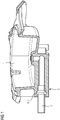
- FIG. 1 shows a partial sectional view of a gas-supply connection assembly.
- the connection assembly in the present case is related to a gas burner of a domestic gas stove or gas cooking appliance, and comprises in the present embodiment a gas-burner body 1 of a gas burner of the gas stove and a gas supply line 2 or gas supply pipe.
- the gas supply line 2 is intended for supplying gas to the gas burner for operating the same. Therefore, a gas-tight connection or interconnection between the gas supply line 2 and a gas inlet port 3 of the gas-burner body 1 is required.
- FIG. 2 and FIG. 3 respectively showing the gas-supply assembly in the pre-assembled state, prior to assembly, and in a partly assembled state.
- a straight end section of the gas supply line 2 i.e. a straight end section of the gas supply line 2 that is preferably free from bulges, bumps and/or recesses, is provided and, in accordance with the direction as indicated by the arrow given in FIG. 2 , is inserted into a bushing 4 of the gas inlet port 3.
- the bushing 4 may be implemented as a cylindrical bore or hole, wherein the inner diameter of the bushing 4 is matched with the outer diameter of the gas supply line 2 such that the gas supply line 2 fits and can be inserted into the bushing 4.
- a cross sectional constriction acting as an abutment shoulder 5 for abutment of the gas supply line 2, in particular to define and/or restrict the length of the gas supply line 2 to be inserted into the bushing.
- the bushing 4 at a certain distance from its outer and inner ends comprises an indentation 6, and plastic deformation of the gas supply line 2 is conducted in such a way and/or applying the force/s to the gas supply line 2 automatically causes that the gas supply line 2 in particular in the region of the indentation 6 plastically deforms into and fills the indentation 6 with a corresponding bulge section 7. This corresponds to the situation as shown in FIG. 1 .
- the bulge section 7 is shaped as a circumferential flange, with two opposing axial faces. One of the axial faces is parallel to the radial direction and the other one located further inwards is inclined relative to the radial direction.
- the indentation 6 is shaped accordingly, e.g. as a circumferential groove, with two opposing axial faces, where one is parallel to the radial direction and the other one is inclined relative to the radial direction.
- the indentation 6 and bulge section 7 in the present example are shaped such that the interconnection between the bulge section 7 and indentation 6 is a type of barbed-hook shaped connection.
- the barbed-hook effect in particular is established to work against forces acting on the gas supply line 2 in a direction out of the bushing 4. Hence a comparatively tight connection both relative to mechanical strength and leakproofness can be obtained
- FIG. 4 is related to a gas burner body of a further embodiment of the gas-supply connection assembly.
- the difference to the embodiment shown in FIG. 1 to FIG. 3 essentially lies in the shape of the indentation 6, which in the embodiment of FIG. 4 may have a more elliptical cross section.
- the indentation may comprise at inner walls thereof one or more protuberances extending radially inwardly.
- the protuberances may have an elliptical shape. Upon plastic deformation, the material of the gas supply line undergoing plastic deformation may flow around the protuberances and enclosed tightly enclose them, which may lead to improved leakproofness.
Landscapes
- Engineering & Computer Science (AREA)
- General Engineering & Computer Science (AREA)
- Mechanical Engineering (AREA)
- Chemical & Material Sciences (AREA)
- Combustion & Propulsion (AREA)
- Gas Burners (AREA)
- Feeding And Controlling Fuel (AREA)
Claims (8)
- Gaszuleitungsanschlussanordnung, umfassend eine Gaszuleitungsleitung (2) und eine Gaseintrittsöffnung (3) eines Gasverbrauchers (1), wobei die Gaszuleitungsanordnung die Gaszuleitungsleitung (2) gasdicht mit der Gaseintrittsöffnung (3) verbindet, dadurch gekennzeichnet, dass die Gaszuleitungsleitung (2) in die Gaseintrittsöffnung (3) eingeführt und damit verbunden wird, wobei ein Ausstülpabschnitt (7), der im eingeführten Zustand durch plastische Verformung davon an einem Außenumfang der Gaszuleitungsleitung (2) bewirkt wird, in formschlüssiger arretierender Weise in gasdichten Eingriff in eine gegebene Einbuchtung (6) in einer Innenhülse (4) der Gaseintrittsöffnung (3) kommt, wobei die Einbuchtung (6) mindestens einen sich verjüngenden Abschnitt umfasst, wobei der Ausstülpabschnitt (7) und die Einbuchtung (6) so geformt sind, dass eine widerhakenförmige Verbindung zwischen der Zuleitungsleitung (2) und der Gaseintrittsöffnung (3) hergestellt wird.
- Gaszuleitungsanschlussanordnung nach Anspruch 1, wobei der Ausstülpabschnitt (7) und die Einbuchtung (6) in axialer Richtung in einem Innenabschnitt der Hülse (4) gebildet sind.
- Gaszuleitungsanschlussanordnung nach Anspruch 1 oder 2, wobei die Einbuchtung (6) mindestens einen Vorsprung umfasst, der sich von einer Innenfläche der Einbuchtung (6) radial einwärts erstreckt.
- Gaszuleitungsanschlussanordnung nach mindestens einem der Ansprüche 1 bis 3, wobei der Ausstülpabschnitt (7) als Vorsprung vom Flanschtyp implementiert ist.
- Gaszuleitungsanschlussanordnung nach mindestens einem der Ansprüche 1 bis 4, wobei die Gaseintrittsöffnung (3) eine Querschnitteinengung umfasst, die als Anliegeschulter (5) wirkt, an der ein axialer Endabschnitt der Zuleitungsleitung in dem eingeführten Zustand anliegt.
- Verfahren zum gasdichten Anschließen einer Gaszuleitungsleitung (2) an eine Gaseintrittsöffnung (3), die an einem Gasverbraucher (1) implementiert ist, dadurch gekennzeichnet, dass ein Anschlussabschnitt der Gaszuleitungsleitung (2) zuerst in eine Hülse (4) der Gaseinlassöffnung (3) eingeführt wird und dann plastisch verformt wird, so dass ein Ausstülpabschnitt (7) innerhalb der Hülse (4) an einem Außenumkreis der Zuleitungsleitung (2) gebildet wird, so dass der Ausstülpabschnitt (7) in formschlüssiger und gasdichter Weise in Eingriff mit einer gegebenen gegengleichen Einbuchtung (6) kommt, die in einem Innenumkreis der Hülse (4) gebildet ist, wobei mindestens ein Abschnitt der Einbuchtung (6) sich verjüngt, wobei der Ausstülpabschnitt (7) und die Einbuchtung (6) so gebildet sind, dass eine widerhakenförmige Verbindung zwischen Zuleitungsleitung (2) und Gaseintrittsöffnung (3) hergestellt wird.
- Verfahren nach Anspruch 6, wobei der Ausstülpabschnitt (7) so gebildet ist, dass die Gaszuleitungsleitung (2) in die Hülse (4) gepresst wird, insbesondere durch Anwenden einer axialen Kraft oder durch Anlegen einer Kombination aus einer axialen und Torsionskraft auf die Gaszuleitungsleitung (2).
- Gaskochgerät, umfassend mindestens einen Gasbrenner und eine Gaszuleitungsanschlussanordnung gemäß einem der Ansprüche 1 bis 4, wodurch eine Gaszuleitungsleitung (2) an eine Gaseintrittsöffnung (3) des Gasbrenners angeschlossen wird.
Priority Applications (7)
| Application Number | Priority Date | Filing Date | Title |
|---|---|---|---|
| ES14168651.9T ES2690331T3 (es) | 2014-05-16 | 2014-05-16 | Conjunto de conexión de suministro de gas, un método para conectar una conducción de suministro de gas a un orificio de entrada de gas, y un aparato de cocina a gas |
| EP14168651.9A EP2944880B1 (de) | 2014-05-16 | 2014-05-16 | Gaszuleitungsanschlussanordnung, Verfahren zum Anschließen einer Gaszuleitung an eine Gaseintrittsöffnung und Gaskochgerät |
| BR112016022993-2A BR112016022993B1 (pt) | 2014-05-16 | 2015-05-05 | Montagem de conexão de alimentação de gás, método de conexão estanque ao gás e aparelho de cocção a gás |
| US15/126,320 US10451286B2 (en) | 2014-05-16 | 2015-05-05 | Gas-supply connection assembly, a method of connecting a gas supply line to a gas inlet port, and a gas cooking appliance |
| PCT/EP2015/059784 WO2015173058A1 (en) | 2014-05-16 | 2015-05-05 | Gas-supply connection assembly, a method of connecting a gas supply line to a gas inlet port, and a gas cooking appliance |
| CN201580017243.9A CN106133445B (zh) | 2014-05-16 | 2015-05-05 | 燃气供应连接组件、连接方法以及燃气烹饪器具 |
| AU2015261174A AU2015261174B2 (en) | 2014-05-16 | 2015-05-05 | Gas-supply connection assembly, a method of connecting a gas supply line to a gas inlet port, and a gas cooking appliance |
Applications Claiming Priority (1)
| Application Number | Priority Date | Filing Date | Title |
|---|---|---|---|
| EP14168651.9A EP2944880B1 (de) | 2014-05-16 | 2014-05-16 | Gaszuleitungsanschlussanordnung, Verfahren zum Anschließen einer Gaszuleitung an eine Gaseintrittsöffnung und Gaskochgerät |
Publications (2)
| Publication Number | Publication Date |
|---|---|
| EP2944880A1 EP2944880A1 (de) | 2015-11-18 |
| EP2944880B1 true EP2944880B1 (de) | 2018-07-11 |
Family
ID=50721697
Family Applications (1)
| Application Number | Title | Priority Date | Filing Date |
|---|---|---|---|
| EP14168651.9A Active EP2944880B1 (de) | 2014-05-16 | 2014-05-16 | Gaszuleitungsanschlussanordnung, Verfahren zum Anschließen einer Gaszuleitung an eine Gaseintrittsöffnung und Gaskochgerät |
Country Status (7)
| Country | Link |
|---|---|
| US (1) | US10451286B2 (de) |
| EP (1) | EP2944880B1 (de) |
| CN (1) | CN106133445B (de) |
| AU (1) | AU2015261174B2 (de) |
| BR (1) | BR112016022993B1 (de) |
| ES (1) | ES2690331T3 (de) |
| WO (1) | WO2015173058A1 (de) |
Families Citing this family (1)
| Publication number | Priority date | Publication date | Assignee | Title |
|---|---|---|---|---|
| ES2728084A1 (es) | 2018-04-18 | 2019-10-22 | Bsh Electrodomesticos Espana Sa | Soporte de sarten, cocina de gas, y metodo para producir un soporte de sarten |
Citations (1)
| Publication number | Priority date | Publication date | Assignee | Title |
|---|---|---|---|---|
| US20010030422A1 (en) * | 1996-10-07 | 2001-10-18 | Universal Tubular Systems, Inc. | Conduit connector and method |
Family Cites Families (28)
| Publication number | Priority date | Publication date | Assignee | Title |
|---|---|---|---|---|
| US2089790A (en) * | 1935-07-24 | 1937-08-10 | Texas Co | Method of forming a rolled joint |
| US2949319A (en) * | 1954-08-18 | 1960-08-16 | Gen Motors Corp | Pipe coupling between relatively hard and soft tubes |
| US3112564A (en) * | 1961-10-25 | 1963-12-03 | William J Murray | Method of forming a brazed lock joint |
| US3817562A (en) * | 1972-07-14 | 1974-06-18 | Numatics Inc | Connector for plastic tube |
| SE7505866L (sv) * | 1974-06-06 | 1975-12-08 | Boeing Co | Kopplingshylsa |
| US3924883A (en) * | 1974-06-12 | 1975-12-09 | Weatherhead Co | Hose coupling |
| US4330144A (en) * | 1974-11-27 | 1982-05-18 | Ridenour Ralph Gaylord | Tube fitting assembly with deformable seal |
| US4142843A (en) * | 1977-03-30 | 1979-03-06 | Murray Corporation | Compressor block and tube assembly |
| FR2488354A1 (fr) * | 1980-08-06 | 1982-02-12 | Nadella | Dispositif de transmission comportant un joint de cardan ou autre organe d'accouplement |
| GB2138557B (en) * | 1983-04-22 | 1986-02-12 | Douglas Allison Mitchell | Valve assembly for gas burner |
| IT211621Z2 (it) * | 1986-01-17 | 1989-04-07 | Murray Europ | Accoppiamento a tenuta tubo-flangia mediante anello di elastomero e ricalcatura. |
| DE3720620A1 (de) * | 1986-12-22 | 1988-07-07 | Rhydcon Groten Gmbh & Co Kg | Verfahren zur herstellung von rohrverbindungen fuer hochdruckhydraulikleitungen |
| US4887853A (en) * | 1987-08-28 | 1989-12-19 | Itt Corporation | Method and apparatus for providing a unitary assembly of tubing and a terminating fitting |
| DE4211959A1 (de) * | 1992-04-09 | 1993-10-14 | Cipo Industrieprodukt Gmbh | Rohrverbindung |
| BR9401280A (pt) * | 1994-03-24 | 1994-10-11 | Helio Lanfranchi Seabra | Aperfeiçoamento aplicado em processo de travamento de conexão giratória. |
| DE29521617U1 (de) * | 1994-05-07 | 1997-11-20 | Walterscheid Rohrverbindungstechnik GmbH, 53797 Lohmar | Rohr mit einem Anschlußabschnitt und Rohrverbindung |
| US5607194A (en) * | 1995-04-20 | 1997-03-04 | Universal Enterprises, Inc. | Member and tube assembly |
| CA2266500C (en) * | 1996-10-07 | 2008-08-19 | Universal Tubular Systems, Inc. | Conduit connector and method |
| FR2865522B1 (fr) * | 2004-01-27 | 2006-03-03 | Staubli Sa Ets | Element femelle de raccord, raccord rapide et installation de remplissage comprenant un tel element femelle |
| JP2006322609A (ja) * | 2005-04-21 | 2006-11-30 | Denso Corp | パイプの固定構造およびパイプの固定方法 |
| DE102006038841A1 (de) * | 2006-08-18 | 2008-02-21 | Robert Bosch Gmbh | Vorrichtung zur axialen Verbindung eines äusseren Rohrteils mit einem in das Rohrteil eingreifenden koaxialen Zapfenteil oder inneren Rohrteil |
| WO2009044775A1 (ja) * | 2007-10-01 | 2009-04-09 | Toki Engineering Co., Ltd. | 金属管の結合方法、結合構造、フランジ付き管、及びその形成方法 |
| KR20110096650A (ko) * | 2010-02-23 | 2011-08-31 | 주식회사 화승알앤에이 | 튜브-소켓 어셈블리 및 그 제조 방법 |
| US9091376B2 (en) * | 2010-12-30 | 2015-07-28 | Eaton Corporation | Method of forming an internal tube beadlock |
| EP2673543B1 (de) * | 2011-02-08 | 2015-05-27 | Emer S.p.a. | Kopplungsvorrichtung |
| US9297537B2 (en) * | 2011-07-14 | 2016-03-29 | General Electric Company | Orifice holder and tube assembly for use with a gas-fueled appliance |
| WO2013160790A1 (de) * | 2012-04-27 | 2013-10-31 | BSH Bosch und Siemens Hausgeräte GmbH | Gasanschluss für ein gasbeheiztes gargerät |
| ITVE20150018A1 (it) * | 2015-04-24 | 2016-10-24 | Ego Elektro Geraetebau Gmbh | Bruciatore a gas perfezionato per apparecchi di cottura. |
-
2014
- 2014-05-16 EP EP14168651.9A patent/EP2944880B1/de active Active
- 2014-05-16 ES ES14168651.9T patent/ES2690331T3/es active Active
-
2015
- 2015-05-05 AU AU2015261174A patent/AU2015261174B2/en active Active
- 2015-05-05 CN CN201580017243.9A patent/CN106133445B/zh active Active
- 2015-05-05 WO PCT/EP2015/059784 patent/WO2015173058A1/en not_active Ceased
- 2015-05-05 US US15/126,320 patent/US10451286B2/en active Active
- 2015-05-05 BR BR112016022993-2A patent/BR112016022993B1/pt active IP Right Grant
Patent Citations (1)
| Publication number | Priority date | Publication date | Assignee | Title |
|---|---|---|---|---|
| US20010030422A1 (en) * | 1996-10-07 | 2001-10-18 | Universal Tubular Systems, Inc. | Conduit connector and method |
Also Published As
| Publication number | Publication date |
|---|---|
| CN106133445A (zh) | 2016-11-16 |
| US10451286B2 (en) | 2019-10-22 |
| US20170082293A1 (en) | 2017-03-23 |
| EP2944880A1 (de) | 2015-11-18 |
| ES2690331T3 (es) | 2018-11-20 |
| AU2015261174B2 (en) | 2019-10-24 |
| CN106133445B (zh) | 2019-06-25 |
| WO2015173058A1 (en) | 2015-11-19 |
| AU2015261174A1 (en) | 2016-09-22 |
| BR112016022993B1 (pt) | 2021-03-30 |
Similar Documents
| Publication | Publication Date | Title |
|---|---|---|
| KR101886553B1 (ko) | 수지제관 이음매 | |
| EP3097335B1 (de) | Fluidkupplung mit feststellverbindung | |
| JP2004509304A (ja) | 内部スエージング式継手金具 | |
| US10359132B2 (en) | Press fitting for a threaded connection and method for attaching a fitting to a threaded connection | |
| KR101886552B1 (ko) | 수지제관 이음매 | |
| US20140062078A1 (en) | Pipe connector apparatus | |
| TW201100684A (en) | Fluid fitting | |
| US20080277931A1 (en) | Connection for conduits and method for making it | |
| CN104321565A (zh) | 用于高压接头的复合滑动垫圈 | |
| JP2017534823A (ja) | 管状要素への連結用継手、配管連結体、および管状要素への継手連結方法 | |
| JP5923579B2 (ja) | 樹脂製管継手 | |
| US9169950B2 (en) | Connector for flexible hoses | |
| JP5923578B2 (ja) | 樹脂製管継手 | |
| US10451286B2 (en) | Gas-supply connection assembly, a method of connecting a gas supply line to a gas inlet port, and a gas cooking appliance | |
| EP3660376B1 (de) | Rohrverbindung und rohrverbindungsstruktur | |
| US7722093B2 (en) | Fitting | |
| JP6850478B2 (ja) | 口金具の製造方法 | |
| KR20160069534A (ko) | 고강도 조립 구조를 갖는 연료레일 | |
| CA2606722A1 (en) | Method of attaching tubing to a metal fitting | |
| RU2258860C1 (ru) | Шланговое соединение и способ его сборки | |
| EP4113012A1 (de) | Heiz-/kühlsystemverteiler | |
| HK40065604A (zh) | 用於连接至管形件、管路连接的接头 | |
| JP2018503033A (ja) | ホースコネクタ及びそのようなホースコネクタに流体ラインの一端を液密接続するための方法 | |
| JPH056286U (ja) | 管継手 |
Legal Events
| Date | Code | Title | Description |
|---|---|---|---|
| PUAI | Public reference made under article 153(3) epc to a published international application that has entered the european phase |
Free format text: ORIGINAL CODE: 0009012 |
|
| AK | Designated contracting states |
Kind code of ref document: A1 Designated state(s): AL AT BE BG CH CY CZ DE DK EE ES FI FR GB GR HR HU IE IS IT LI LT LU LV MC MK MT NL NO PL PT RO RS SE SI SK SM TR |
|
| AX | Request for extension of the european patent |
Extension state: BA ME |
|
| 17P | Request for examination filed |
Effective date: 20160518 |
|
| RBV | Designated contracting states (corrected) |
Designated state(s): AL AT BE BG CH CY CZ DE DK EE ES FI FR GB GR HR HU IE IS IT LI LT LU LV MC MK MT NL NO PL PT RO RS SE SI SK SM TR |
|
| STAA | Information on the status of an ep patent application or granted ep patent |
Free format text: STATUS: EXAMINATION IS IN PROGRESS |
|
| 17Q | First examination report despatched |
Effective date: 20170412 |
|
| REG | Reference to a national code |
Ref country code: DE Ref legal event code: R079 Ref document number: 602014028170 Country of ref document: DE Free format text: PREVIOUS MAIN CLASS: F24C0003000000 Ipc: B21D0039060000 |
|
| GRAP | Despatch of communication of intention to grant a patent |
Free format text: ORIGINAL CODE: EPIDOSNIGR1 |
|
| STAA | Information on the status of an ep patent application or granted ep patent |
Free format text: STATUS: GRANT OF PATENT IS INTENDED |
|
| RIC1 | Information provided on ipc code assigned before grant |
Ipc: F16L 13/14 20060101ALI20171205BHEP Ipc: F24C 3/08 20060101ALI20171205BHEP Ipc: B21D 39/06 20060101AFI20171205BHEP Ipc: F24C 3/00 20060101ALI20171205BHEP |
|
| INTG | Intention to grant announced |
Effective date: 20180102 |
|
| GRAS | Grant fee paid |
Free format text: ORIGINAL CODE: EPIDOSNIGR3 |
|
| GRAA | (expected) grant |
Free format text: ORIGINAL CODE: 0009210 |
|
| STAA | Information on the status of an ep patent application or granted ep patent |
Free format text: STATUS: THE PATENT HAS BEEN GRANTED |
|
| AK | Designated contracting states |
Kind code of ref document: B1 Designated state(s): AL AT BE BG CH CY CZ DE DK EE ES FI FR GB GR HR HU IE IS IT LI LT LU LV MC MK MT NL NO PL PT RO RS SE SI SK SM TR |
|
| REG | Reference to a national code |
Ref country code: GB Ref legal event code: FG4D |
|
| REG | Reference to a national code |
Ref country code: CH Ref legal event code: EP |
|
| REG | Reference to a national code |
Ref country code: AT Ref legal event code: REF Ref document number: 1016358 Country of ref document: AT Kind code of ref document: T Effective date: 20180715 |
|
| REG | Reference to a national code |
Ref country code: IE Ref legal event code: FG4D |
|
| REG | Reference to a national code |
Ref country code: DE Ref legal event code: R096 Ref document number: 602014028170 Country of ref document: DE |
|
| REG | Reference to a national code |
Ref country code: NL Ref legal event code: MP Effective date: 20180711 |
|
| REG | Reference to a national code |
Ref country code: ES Ref legal event code: FG2A Ref document number: 2690331 Country of ref document: ES Kind code of ref document: T3 Effective date: 20181120 |
|
| REG | Reference to a national code |
Ref country code: LT Ref legal event code: MG4D |
|
| REG | Reference to a national code |
Ref country code: AT Ref legal event code: MK05 Ref document number: 1016358 Country of ref document: AT Kind code of ref document: T Effective date: 20180711 |
|
| PG25 | Lapsed in a contracting state [announced via postgrant information from national office to epo] |
Ref country code: NL Free format text: LAPSE BECAUSE OF FAILURE TO SUBMIT A TRANSLATION OF THE DESCRIPTION OR TO PAY THE FEE WITHIN THE PRESCRIBED TIME-LIMIT Effective date: 20180711 |
|
| PG25 | Lapsed in a contracting state [announced via postgrant information from national office to epo] |
Ref country code: BG Free format text: LAPSE BECAUSE OF FAILURE TO SUBMIT A TRANSLATION OF THE DESCRIPTION OR TO PAY THE FEE WITHIN THE PRESCRIBED TIME-LIMIT Effective date: 20181011 Ref country code: LT Free format text: LAPSE BECAUSE OF FAILURE TO SUBMIT A TRANSLATION OF THE DESCRIPTION OR TO PAY THE FEE WITHIN THE PRESCRIBED TIME-LIMIT Effective date: 20180711 Ref country code: IS Free format text: LAPSE BECAUSE OF FAILURE TO SUBMIT A TRANSLATION OF THE DESCRIPTION OR TO PAY THE FEE WITHIN THE PRESCRIBED TIME-LIMIT Effective date: 20181111 Ref country code: PL Free format text: LAPSE BECAUSE OF FAILURE TO SUBMIT A TRANSLATION OF THE DESCRIPTION OR TO PAY THE FEE WITHIN THE PRESCRIBED TIME-LIMIT Effective date: 20180711 Ref country code: AT Free format text: LAPSE BECAUSE OF FAILURE TO SUBMIT A TRANSLATION OF THE DESCRIPTION OR TO PAY THE FEE WITHIN THE PRESCRIBED TIME-LIMIT Effective date: 20180711 Ref country code: GR Free format text: LAPSE BECAUSE OF FAILURE TO SUBMIT A TRANSLATION OF THE DESCRIPTION OR TO PAY THE FEE WITHIN THE PRESCRIBED TIME-LIMIT Effective date: 20181012 Ref country code: SE Free format text: LAPSE BECAUSE OF FAILURE TO SUBMIT A TRANSLATION OF THE DESCRIPTION OR TO PAY THE FEE WITHIN THE PRESCRIBED TIME-LIMIT Effective date: 20180711 Ref country code: NO Free format text: LAPSE BECAUSE OF FAILURE TO SUBMIT A TRANSLATION OF THE DESCRIPTION OR TO PAY THE FEE WITHIN THE PRESCRIBED TIME-LIMIT Effective date: 20181011 Ref country code: FI Free format text: LAPSE BECAUSE OF FAILURE TO SUBMIT A TRANSLATION OF THE DESCRIPTION OR TO PAY THE FEE WITHIN THE PRESCRIBED TIME-LIMIT Effective date: 20180711 Ref country code: RS Free format text: LAPSE BECAUSE OF FAILURE TO SUBMIT A TRANSLATION OF THE DESCRIPTION OR TO PAY THE FEE WITHIN THE PRESCRIBED TIME-LIMIT Effective date: 20180711 |
|
| PG25 | Lapsed in a contracting state [announced via postgrant information from national office to epo] |
Ref country code: HR Free format text: LAPSE BECAUSE OF FAILURE TO SUBMIT A TRANSLATION OF THE DESCRIPTION OR TO PAY THE FEE WITHIN THE PRESCRIBED TIME-LIMIT Effective date: 20180711 Ref country code: AL Free format text: LAPSE BECAUSE OF FAILURE TO SUBMIT A TRANSLATION OF THE DESCRIPTION OR TO PAY THE FEE WITHIN THE PRESCRIBED TIME-LIMIT Effective date: 20180711 Ref country code: LV Free format text: LAPSE BECAUSE OF FAILURE TO SUBMIT A TRANSLATION OF THE DESCRIPTION OR TO PAY THE FEE WITHIN THE PRESCRIBED TIME-LIMIT Effective date: 20180711 |
|
| REG | Reference to a national code |
Ref country code: DE Ref legal event code: R097 Ref document number: 602014028170 Country of ref document: DE |
|
| PG25 | Lapsed in a contracting state [announced via postgrant information from national office to epo] |
Ref country code: EE Free format text: LAPSE BECAUSE OF FAILURE TO SUBMIT A TRANSLATION OF THE DESCRIPTION OR TO PAY THE FEE WITHIN THE PRESCRIBED TIME-LIMIT Effective date: 20180711 Ref country code: CZ Free format text: LAPSE BECAUSE OF FAILURE TO SUBMIT A TRANSLATION OF THE DESCRIPTION OR TO PAY THE FEE WITHIN THE PRESCRIBED TIME-LIMIT Effective date: 20180711 Ref country code: RO Free format text: LAPSE BECAUSE OF FAILURE TO SUBMIT A TRANSLATION OF THE DESCRIPTION OR TO PAY THE FEE WITHIN THE PRESCRIBED TIME-LIMIT Effective date: 20180711 |
|
| PLBE | No opposition filed within time limit |
Free format text: ORIGINAL CODE: 0009261 |
|
| STAA | Information on the status of an ep patent application or granted ep patent |
Free format text: STATUS: NO OPPOSITION FILED WITHIN TIME LIMIT |
|
| PG25 | Lapsed in a contracting state [announced via postgrant information from national office to epo] |
Ref country code: SM Free format text: LAPSE BECAUSE OF FAILURE TO SUBMIT A TRANSLATION OF THE DESCRIPTION OR TO PAY THE FEE WITHIN THE PRESCRIBED TIME-LIMIT Effective date: 20180711 Ref country code: SK Free format text: LAPSE BECAUSE OF FAILURE TO SUBMIT A TRANSLATION OF THE DESCRIPTION OR TO PAY THE FEE WITHIN THE PRESCRIBED TIME-LIMIT Effective date: 20180711 Ref country code: DK Free format text: LAPSE BECAUSE OF FAILURE TO SUBMIT A TRANSLATION OF THE DESCRIPTION OR TO PAY THE FEE WITHIN THE PRESCRIBED TIME-LIMIT Effective date: 20180711 |
|
| 26N | No opposition filed |
Effective date: 20190412 |
|
| PG25 | Lapsed in a contracting state [announced via postgrant information from national office to epo] |
Ref country code: SI Free format text: LAPSE BECAUSE OF FAILURE TO SUBMIT A TRANSLATION OF THE DESCRIPTION OR TO PAY THE FEE WITHIN THE PRESCRIBED TIME-LIMIT Effective date: 20180711 |
|
| REG | Reference to a national code |
Ref country code: DE Ref legal event code: R119 Ref document number: 602014028170 Country of ref document: DE |
|
| REG | Reference to a national code |
Ref country code: CH Ref legal event code: PL |
|
| PG25 | Lapsed in a contracting state [announced via postgrant information from national office to epo] |
Ref country code: MC Free format text: LAPSE BECAUSE OF FAILURE TO SUBMIT A TRANSLATION OF THE DESCRIPTION OR TO PAY THE FEE WITHIN THE PRESCRIBED TIME-LIMIT Effective date: 20180711 Ref country code: CH Free format text: LAPSE BECAUSE OF NON-PAYMENT OF DUE FEES Effective date: 20190531 Ref country code: LI Free format text: LAPSE BECAUSE OF NON-PAYMENT OF DUE FEES Effective date: 20190531 |
|
| REG | Reference to a national code |
Ref country code: BE Ref legal event code: MM Effective date: 20190531 |
|
| PG25 | Lapsed in a contracting state [announced via postgrant information from national office to epo] |
Ref country code: LU Free format text: LAPSE BECAUSE OF NON-PAYMENT OF DUE FEES Effective date: 20190516 |
|
| PG25 | Lapsed in a contracting state [announced via postgrant information from national office to epo] |
Ref country code: TR Free format text: LAPSE BECAUSE OF FAILURE TO SUBMIT A TRANSLATION OF THE DESCRIPTION OR TO PAY THE FEE WITHIN THE PRESCRIBED TIME-LIMIT Effective date: 20180711 |
|
| PG25 | Lapsed in a contracting state [announced via postgrant information from national office to epo] |
Ref country code: IE Free format text: LAPSE BECAUSE OF NON-PAYMENT OF DUE FEES Effective date: 20190516 Ref country code: DE Free format text: LAPSE BECAUSE OF NON-PAYMENT OF DUE FEES Effective date: 20191203 |
|
| PG25 | Lapsed in a contracting state [announced via postgrant information from national office to epo] |
Ref country code: BE Free format text: LAPSE BECAUSE OF NON-PAYMENT OF DUE FEES Effective date: 20190531 |
|
| PG25 | Lapsed in a contracting state [announced via postgrant information from national office to epo] |
Ref country code: PT Free format text: LAPSE BECAUSE OF FAILURE TO SUBMIT A TRANSLATION OF THE DESCRIPTION OR TO PAY THE FEE WITHIN THE PRESCRIBED TIME-LIMIT Effective date: 20181111 |
|
| PG25 | Lapsed in a contracting state [announced via postgrant information from national office to epo] |
Ref country code: CY Free format text: LAPSE BECAUSE OF FAILURE TO SUBMIT A TRANSLATION OF THE DESCRIPTION OR TO PAY THE FEE WITHIN THE PRESCRIBED TIME-LIMIT Effective date: 20180711 |
|
| PG25 | Lapsed in a contracting state [announced via postgrant information from national office to epo] |
Ref country code: HU Free format text: LAPSE BECAUSE OF FAILURE TO SUBMIT A TRANSLATION OF THE DESCRIPTION OR TO PAY THE FEE WITHIN THE PRESCRIBED TIME-LIMIT; INVALID AB INITIO Effective date: 20140516 Ref country code: MT Free format text: LAPSE BECAUSE OF FAILURE TO SUBMIT A TRANSLATION OF THE DESCRIPTION OR TO PAY THE FEE WITHIN THE PRESCRIBED TIME-LIMIT Effective date: 20180711 |
|
| PG25 | Lapsed in a contracting state [announced via postgrant information from national office to epo] |
Ref country code: MK Free format text: LAPSE BECAUSE OF FAILURE TO SUBMIT A TRANSLATION OF THE DESCRIPTION OR TO PAY THE FEE WITHIN THE PRESCRIBED TIME-LIMIT Effective date: 20180711 |
|
| P01 | Opt-out of the competence of the unified patent court (upc) registered |
Effective date: 20230625 |
|
| PGFP | Annual fee paid to national office [announced via postgrant information from national office to epo] |
Ref country code: GB Payment date: 20250520 Year of fee payment: 12 Ref country code: ES Payment date: 20250612 Year of fee payment: 12 |
|
| PGFP | Annual fee paid to national office [announced via postgrant information from national office to epo] |
Ref country code: IT Payment date: 20250522 Year of fee payment: 12 |
|
| PGFP | Annual fee paid to national office [announced via postgrant information from national office to epo] |
Ref country code: FR Payment date: 20250526 Year of fee payment: 12 |