EP2945175A1 - Dispositif de contact - Google Patents
Dispositif de contact Download PDFInfo
- Publication number
- EP2945175A1 EP2945175A1 EP15167289.6A EP15167289A EP2945175A1 EP 2945175 A1 EP2945175 A1 EP 2945175A1 EP 15167289 A EP15167289 A EP 15167289A EP 2945175 A1 EP2945175 A1 EP 2945175A1
- Authority
- EP
- European Patent Office
- Prior art keywords
- contact
- movable contact
- movable
- protrusion
- piece
- Prior art date
- Legal status (The legal status is an assumption and is not a legal conclusion. Google has not performed a legal analysis and makes no representation as to the accuracy of the status listed.)
- Granted
Links
Images






Classifications
-
- H—ELECTRICITY
- H01—ELECTRIC ELEMENTS
- H01H—ELECTRIC SWITCHES; RELAYS; SELECTORS; EMERGENCY PROTECTIVE DEVICES
- H01H1/00—Contacts
- H01H1/06—Contacts characterised by the shape or structure of the contact-making surface, e.g. grooved
-
- H—ELECTRICITY
- H01—ELECTRIC ELEMENTS
- H01H—ELECTRIC SWITCHES; RELAYS; SELECTORS; EMERGENCY PROTECTIVE DEVICES
- H01H50/00—Details of electromagnetic relays
- H01H50/54—Contact arrangements
- H01H50/541—Auxiliary contact devices
-
- H—ELECTRICITY
- H01—ELECTRIC ELEMENTS
- H01H—ELECTRIC SWITCHES; RELAYS; SELECTORS; EMERGENCY PROTECTIVE DEVICES
- H01H50/00—Details of electromagnetic relays
- H01H50/54—Contact arrangements
- H01H50/56—Contact spring sets
- H01H50/58—Driving arrangements structurally associated therewith; Mounting of driving arrangements on armature
-
- H—ELECTRICITY
- H01—ELECTRIC ELEMENTS
- H01H—ELECTRIC SWITCHES; RELAYS; SELECTORS; EMERGENCY PROTECTIVE DEVICES
- H01H50/00—Details of electromagnetic relays
- H01H50/64—Driving arrangements between movable part of magnetic circuit and contact
- H01H50/641—Driving arrangements between movable part of magnetic circuit and contact intermediate part performing a rectilinear movement
- H01H50/642—Driving arrangements between movable part of magnetic circuit and contact intermediate part performing a rectilinear movement intermediate part being generally a slide plate, e.g. a card
-
- H—ELECTRICITY
- H01—ELECTRIC ELEMENTS
- H01H—ELECTRIC SWITCHES; RELAYS; SELECTORS; EMERGENCY PROTECTIVE DEVICES
- H01H50/00—Details of electromagnetic relays
- H01H50/64—Driving arrangements between movable part of magnetic circuit and contact
- H01H50/645—Driving arrangements between movable part of magnetic circuit and contact intermediate part making a resilient or flexible connection
-
- H—ELECTRICITY
- H01—ELECTRIC ELEMENTS
- H01H—ELECTRIC SWITCHES; RELAYS; SELECTORS; EMERGENCY PROTECTIVE DEVICES
- H01H9/00—Details of switching devices, not covered by groups H01H1/00 - H01H7/00
- H01H9/30—Means for extinguishing or preventing arc between current-carrying parts
- H01H9/46—Means for extinguishing or preventing arc between current-carrying parts using arcing horns
-
- H—ELECTRICITY
- H01—ELECTRIC ELEMENTS
- H01T—SPARK GAPS; OVERVOLTAGE ARRESTERS USING SPARK GAPS; SPARKING PLUGS; CORONA DEVICES; GENERATING IONS TO BE INTRODUCED INTO NON-ENCLOSED GASES
- H01T4/00—Overvoltage arresters using spark gaps
- H01T4/10—Overvoltage arresters using spark gaps having a single gap or a plurality of gaps in parallel
- H01T4/14—Arcing horns
-
- H—ELECTRICITY
- H01—ELECTRIC ELEMENTS
- H01H—ELECTRIC SWITCHES; RELAYS; SELECTORS; EMERGENCY PROTECTIVE DEVICES
- H01H2203/00—Form of contacts
- H01H2203/002—Raised edge
Definitions
- the present invention generally relates to contact devices and in particular relates to a contact device including a fixed contact and a movable contact.
- the electromagnetic relay disclosed in document 1 includes an electromagnet, an armature to be rotated by magnetic force caused by the electromagnet, a movable contact to move in accordance with a rotation of the armature, and a fixed contact to be in contact or separate from the movable contact.
- the armature when a current flows through a coil of the electromagnet, the armature is rotated in a direction according to a flow direction of a current in the coil.
- the movable contact is movable between a position in which the movable contact is in contact with the fixed contact and a position in which the movable contact is separate from the fixed contact, in accordance with such a rotation of the armature.
- the volume of the movable contact decreases, and therefore lifetime of contacts with regard to on and off operation is likely to be shortened, and the contacts are likely to adhered to each other by melting.
- the present invention has aimed to propose a contact device capable of offering an improved breaking performance without requiring changes in volumes of contacts.
- the contact device of one aspect of the present invention includes: a fixed contact member including a fixed contact; and a movable contact member which includes a movable contact and is movable between a position where the movable contact is in contact with the fixed contact and a position where the movable contact is away from the fixed contact.
- At least one of the fixed contact member and the movable contact member further includes a protrusion which protrudes from a face to which a corresponding contact is provided, in a direction same as a protruding direction of the corresponding contact.
- the contact device electromagnettic relay
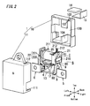
- the contact device of the present invention is not limited to the present embodiment, and may have various configurations within the technical scope of the present invention. Unless otherwise noted, the following descriptions are made based on forward and rearward, left and right, and upward and downward directions defined in FIG. 2 .
- the contact device of the present embodiment includes a case (outer casing) 1 constituted by a body 10 and a cover 11.
- the body 10 is a synthetic resin molded product in a rectangular box shape with an open face.
- the cover 11 is a synthetic resin molded product in a rectangular box shape with an open face.
- the case 1 is assembled by covering the body 10 with the cover 11.
- a coupling method allowing prevention of separation is not limited to the above method.
- the body 10 and the cover 11 may be coupled with adhesive (sealant).
- the contact device of the present embodiment includes a relay body A which is constituted by a driving block, a contact block, and a positioning member 12 and is situated in the case 1 .
- the driving block includes a driver 2, an armature 8, a hinge spring 9, and a card 13.
- the driver 2 is an electromagnet including a bobbin 21, a coil 20 formed by winding a wire around the bobbin 21, an iron core situated in a center of the bobbin 21, and a heel piece 22 .
- the bobbin 21 includes a barrel inside the coil 20, a first flange 210 provided to one axial end of the barrel, and a second flange 211 provided to the other axial end of the barrel. Note that, in this bobbin 21, it is preferable that the barrel and the pair of flanges 210 and 211 be formed integrally by use of insulating material such as synthetic resin.
- the first flange 210 is in a flat rectangular box shape with one open bottom (right side) and one open side (lower face) (see FIG. 2 ).
- the pair of coil terminals 212 are individually connected to both ends of the coil 20. When a voltage is applied between the pair of coil terminals 212 and 212, current flows through the coil 20 and therefore the driver (electromagnet) 2 is excited.
- the heel piece 22 is in an L-shape, and includes a holding piece 220 held by the second flange 211, and a main piece 221 extending from an end of the holding piece 220 to the first flange 210 which are formed integrally by use of magnetic material (see FIG. 1 ).
- the armature 8 includes a driving piece 80 in a band plate shape, and a supporting piece 81 which is in a flat plate shape and is wider than the driving piece 80.
- the driving piece 80 and the supporting piece 81 are formed integrally by use of magnetic material.
- the supporting piece 81 is accommodated in the first flange 210, and is fixed to a first fixing piece 90 of the hinge spring 9 (see FIG. 2 and FIG. 6 ). Further, the supporting piece 81 faces an end of the iron core exposed on an inner bottom of the first flange 210.
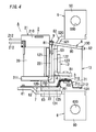
- the driving piece 80 protrudes to an outside of the first flange 210 through the open side (lower face) of the first flange 210. Further, the driving piece 80 abuts on a front end of the main piece 221 of the heel piece 22 (see FIG. 4 ). Note that, there is a projection 82 in a cuboidal shape provided to a front end face (lower end face) of the driving piece 80.
- the hinge spring 9 includes the first fixing piece 90, a second fixing piece 91, and a pair of spring pieces 92 .
- the first fixing piece 90, the second fixing piece 91, and the pair of spring pieces 92 are formed integrally by use of a plate spring (see FIG. 6 ).
- the first fixing piece 90 is in a rectangular flat plate shape and is fixed (swaged) to the supporting piece 81 of the armature 8.
- the second fixing piece 91 is in a rectangular flat plate shape, and is fixed (swaged) to the main piece 221 of the heel piece 22.
- the pair of spring pieces 92 each are in an L-shape, and include opposite ends in a length direction coupled to the first fixing piece 90 and the second fixing piece 91, respectively.
- the armature 8 When the armature 8 is driven by the driver 2, the armature 8 turns around a fulcrum defined by a part of the armature 8 in contact with the main piece 221 of the heel piece 22, in a direction (counterclockwise in FIG. 1 ) in which the supporting piece 81 moves close to the iron core. When the armature 8 is not driven by the driver 2, the armature 8 turns in a direction (clockwise in FIG. 1 ) in which the supporting piece 81 moves away from the iron core.
- the contact block includes a fixed contact 3, a movable contact 4, a first terminal 5, a second terminal 6, and a contact spring 7.
- the contact spring 7 includes multiple (three in the present embodiment) plate springs 70 and an interconnection member 71 (see FIG. 4 ).
- the plate spring 70 includes a main piece 700 in a band shape, an inclined piece 701 extending obliquely from a front end (lower end) of the main piece 700, and an attachment piece 702 in a rectangular shape protruding from a front end (lower end) of the inclined piece 701 in parallel with the main piece 700. As shown in FIG. 6 , these three plate springs 70 are coupled with each other so that the main pieces 700 are in a stack and the attachment pieces 702 are in a stack.
- the interconnection member 71 includes an attachment part 710 in a rectangular shape, an inclined part 711 protruding obliquely downward from a center of a lower end of the attachment part 710, and a connection piece 712 extending from a front end (lower end) of the inclined part 711 in parallel with the attachment part 710 (see FIG. 4 ).
- the attachment part 710 is situated on the attachment pieces 702 of the plate springs 70 .
- the movable contact 4 is provided to a surface (right side) of the attachment part 710 so as to penetrate through the three attachment pieces 702 and the attachment part 710 .
- a front end (lower end) part is wider than a remaining part.
- the connection piece 712 is coupled to the card 13 at the wide front end part.
- the contact spring 7 is connected to the second terminal 6 at a further end part (upper end of the main piece 700 ) of the plate spring 70 (see FIG. 4 ).
- the second terminal 6 includes a terminal piece 60 , a fixing piece 61, an inclined piece 62 , and an interconnection piece 63, which are formed integrally by use of metal.
- the terminal piece 60 is in a rectangular flat plate shape, and includes a screw hole 600 penetrating through its center. A terminal screw is screwed into the screw hole 600 .
- the fixing piece 61 is in a rectangular flat plate shape, and the further end (upper end) of the plate spring 70 of the contact spring 7 is fixed (swaged) to the fixing piece 61.
- the inclined piece 62 is in a rectangular flat plate shape, and extends obliquely downward (in a left lower direction) from the lower end of the fixing piece 61.
- the interconnection piece 63 is in a rectangular flat plate shape, and interconnects the upper end of the terminal piece 60 and the lower end of the inclined piece 62.
- the fixed contact 3 which is to be in contact with the movable contact 4 is provided to the first terminal 5.
- the first terminal 5 includes a terminal piece 50, an attachment piece 51, a supporting piece 52, and an interconnection piece 53, which are formed integrally by use of metal.
- the terminal piece 50 is in a rectangular flat plate shape, and includes a screw hole 500 penetrating through its center. A terminal screw is screwed into the screw hole 500.
- the attachment piece 51 is in a rectangular flat plate shape, and the fixed contact 3 is attached to a center of the attachment piece 51.
- the supporting piece 52 includes: a main piece 520 having the front end connected to the terminal piece 50; and an inclined piece 521 extending obliquely upward from the upper edge of the main piece 520.
- the interconnection piece 53 is in a rectangular flat plate shape, and interconnects the upper end of the inclined piece 521 and the right end of the attachment piece 51.
- the fixed contact 3 and the first terminal 5 constitute a fixed contact member
- the movable contact 4 constitute a movable contact member
- the card 13 of the driving block is made of resilient material (e.g., a metal plate), and is fixed to each of the armature 8 and the contact spring 7.
- the card 13 is in a band shape as shown in FIG. 5 and FIG. 6 , and includes one end in a length direction through which a rectangular hole 130 penetrates, and another end in the length direction bent at the right angle to extend in a thickness direction of the card 13.
- the card 13 is fixed to the armature 8 by swaging the projection 82 inserted into the hole 130. Further, in the card 13, the part which is bent at the right angle (hereinafter referred to as a second fixing part 131 ) is fixed (swaged) to the contact spring 7 (the connection piece 712 of the interconnection member 71 ).
- the positioning member 12 is a synthetic resin molded product including a bottom wall 120, a first longitudinal wall 121, a second longitudinal wall 122, a third longitudinal wall 123, a fourth longitudinal wall 124, and a fifth longitudinal wall 125 which are formed integrally.
- the bottom wall 120 is in a flat hook shape.
- the first longitudinal wall 121 to the fifth longitudinal wall 125 are in an almost rectangular flat plate shape, and extend in the same direction from a surface of the bottom wall 120 .
- the first longitudinal wall 121, the second longitudinal wall 122, and the third longitudinal wall 123 are arranged in parallel with each other at intervals on a narrow part of the bottom wall 120.
- a space between the first longitudinal wall 121 and the second longitudinal wall 122 is defined as a first groove 126
- a space between the second longitudinal wall 122 and the third longitudinal wall 123 is defined as a second groove 127 .
- the fourth longitudinal wall 124 and the fifth longitudinal wall 125 are arranged in parallel with each other at an interval on an end of a broad part of the bottom wall 120.
- a space between the fourth longitudinal wall 124 and the fifth longitudinal wall 125 is defined as a third groove 128.
- a pair of holding holes (first holding holes) 1260 are arranged in a length direction of the first groove 126 in a bottom of the first groove 126.
- a pair of holding holes (second holding holes) 1270 are arranged in a length direction of the second groove 127 in a bottom of the second groove 127.
- a pair of holding holes (third holding holes) 1280 are arranged in a length direction of the third groove 128 in a bottom of the third groove 128.
- Each of the pair of first holding holes 1260, the pair of second holding holes 1270, and the pair of third holding holes 1280 is a rectangular through hole penetrating through the bottom wall 120. Note that, protrusions are provided to an inner circumferential surface of each of the first holding holes 1260, the second holding holes 1270, and the third holding holes 1280 .
- the main piece 221 of the heel piece 22 constituting the driver 2 is inserted into the first groove 126 .
- This main piece 221 includes a pair of protrusions. The pair of protrusions are pressed into the first holding holes 1260, and thereby the main piece 221 of the heel piece 22 is held and positioned in the first groove 126 (see FIG. 4 ).
- the interconnection piece 53 of the first terminal 5 is inserted into the second groove 127.
- the interconnection piece 53 also includes a pair of protrusions 530 (see FIG. 6 ). The pair of protrusions 530 are pressed into the second holding holes 1270 , and thereby the interconnection piece 53 of the first terminal 5 is held and positioned in the second groove 127 (see FIG. 4 ).
- the interconnection piece 63 of the second terminal 6 is inserted into the third groove 128.
- the interconnection piece 63 also includes a pair of protrusions. The pair of protrusions are pressed into the third holding holes 1280, and thereby the interconnection piece 63 of the second terminal 6 is held and positioned in the third groove 128 (see FIG. 4 ).
- the positioning member 12 is configured to define a positional relationship between the armature 8, the driver 2, the fixed contact 3, the movable contact 4 , the contact spring 7, and the card 13. Further, the driver 2, the first terminal 5, and the second terminal 6 are held by the positioning member 12 to constitute the relay body A .
- the coil terminals 212 of the driver 2 protrude to an outside of the body 10 through a groove 102 provided to an upper side plate of the body 10 (see FIG. 1 ).
- a cuboidal rib 103 which has a length direction parallel to the forward and rearward direction and protrudes outward (upward) from a surface (upper face) of the side plate.
- the arc extinguishing member placed inside a space surrounded by the driver 2, the armature 8, contacts (the fixed contact 3 and the movable contact 4 ), and the card 13.
- the arc extinguishing member is constituted by a permanent magnet 14 and a yoke 15.
- the permanent magnet 14 is in a rectangular flat plate shape, and is magnetized to have different poles in a thickness direction. In the forward and rearward direction, the yoke 15 is in an L-shape.
- the permanent magnet 14 and the yoke 15 are accommodated in an accommodation part 104 provided to the body 10 .
- the accommodation part 104 is in a box shape whose outer shape is an L-shape in the forward and rearward direction, and protrudes forward from the bottom plate 100 of the body 10 (see FIG. 2 ). Further, the accommodation part 104 is hollow, and therefore the permanent magnet 14 and the yoke 15 are inserted into the accommodation part 104 through an insertion opening 1040 formed in a rear side of the body 10 and are accommodated (see FIG. 3 ).
- the second fixing part 131 of the card 13 is engaged with the connection piece 712 of the contact spring 7, and thereafter the driver 2, the first terminal 5, and the second terminal 6 are held by the positioning member 12. Thereafter, the first fixing part (hole 130 ) of the card 13 is engaged with the projection 82 of the armature 8, and thereby the relay body A is assembled.
- the relay body A is accommodated in the body 10.
- the rear end part of the interconnection piece 63 of the second terminal 6 is pressed into the hole 101A of the bottom plate 100 of the body 10, and thereby the relay body A is positioned and fixed to the body 10 .
- the case 1 is assembled.
- the permanent magnet 14 and the yoke 15 are accommodated in the accommodation part 104 of the body 10, and thereby assembling of the contact device of the present embodiment is completed.
- the driver 2 While no voltage is applied between the coil terminals 212, the driver 2 does not operate the armature 8. Therefore, the contact spring 7 is not pulled by the card 13, and the movable contact 4 and the fixed contact 3 face each other to form a predetermined gap therebetween. At this time, the first terminal 5 and the second terminal 6 are in a non-conduction state (off-state).
- the driver 2 operates the armature 8, and the armature 8 rotates counterclockwise. Therefore, the contact spring 7 is pulled by the card 13 and is bent in a right direction. Therefore, the movable contact 4 is in contact with the fixed contact 3. At this time, the first terminal 5 and the second terminal 6 are in a conduction state (on-state).
- the contact device of the present embodiment accommodates, in the accommodation part 104 of the body 10, the arc extinguishing member constituted by the permanent magnet 14 and the yoke 15 .
- the permanent magnet 14 and the yoke 15 form a magnetic field around the fixed contact 3 and the movable contact 4, and thereby an arc is elongated by electromagnetic force caused by the magnetic field, and this results in extinguishment of the arc.
- one of methods of moving the arc away from the movable contact 4 may be a method of reducing a level difference between a top part of the movable contact 4 (part to be in contact with the fixed contact 3 ) and the surface of the attachment part 710.
- this method when the height of the movable contact 4 is reduced, the arc occurring on the movable contact 4 easily moves toward the surface of the attachment part 710.
- the volume of the movable contact 4 is decreased, and therefore lifetime of contacts regarding on and off operation may be shortened, and contacts are likely to adhere to each other by melting.
- the present embodiment can solve the above problem by the following method without changing the height of the movable contact 4 .
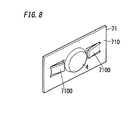
- FIG. 8 is an enlarged view illustrating a primary part of the contact device of the present embodiment.
- protrusions 7100 are provided to the attachment part 710 to obtain the same effect as in a case where a level difference between the top part of the movable contact 4 and the surface of the attachment part 710 (face to which the movable contact 4 is provided) is decreased.
- the movable contact 4 is attached to a center of the attachment part 710 in a rectangular plate shape elongated in the forward and rearward direction, and a pair of protrusions 7100 are provided to opposite sides with regard to the movable contact 4 in the forward and rearward direction.
- Each protrusion 7100 is formed by cutting and arising part of the attachment part 710.
- each protrusion 7100 an end close to the movable contact 4 in the forward and rearward direction and both ends in the upward and downward direction are separated from the attachment part 710 by cutting, and the end close to the movable contact 4 is made to protrude in the same direction as the protruding direction of the movable contact 4. Consequently, it is possible to obtain the same effect as in the case where the level difference between the top part of the movable contact 4 and the surface of the attachment part 710 is decreased.
- the volume of the movable contact 4 is not decreased, the arc occurring on the movable contact 4 may easily move from the movable contact 4 to the protrusion 7100 of the attachment part 710.
- the lifetime of contacts can be prolonged.
- the volume of the movable contact 4 is not decreased, there are advantages that the lifetime of contacts with regard to the on and off operation can be maintained and adhesion of the movable contact 4 caused by melting is not likely to occur.
- a necessary step is only cutting and arising part of the attachment part 710, and therefore there are advantages that processing becomes easy and it is easy to adjust the level difference after assembling.
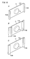
- FIG. 9A to FIG. 9C are enlarged views illustrating primary parts of other examples of the contact device of the present embodiment.
- the protrusion 7100 is formed by cutting and arising part of the attachment part 710 of the interconnection member 71.
- the protrusion 7100 may be in another shape.
- protrusions 7101 are formed on the attachment part 710 so as to be in front of and in back of the movable contact 4. Each protrusion 7101 is formed by making protruding part of the attachment part 710 in the same direction as the protruding direction of the movable contact 4 to be in a semispherical shape.
- protrusions 7102 are formed on the attachment part 710 so as to be in front of and in back of the movable contact 4. Each protrusion 7102 is part of the attachment part 710 and is elongated in the upward and downward direction and protrudes in the same direction as the protruding direction of the movable contact 4.
- FIG. 9A protrusions 7101 are formed on the attachment part 710 so as to be in front of and in back of the movable contact 4.
- Each protrusion 7101 is formed by making protruding part of the attachment part 710 in the same direction as the protruding direction of the movable contact 4 to be in a semispherical shape.
- protrusions 7103 are formed on the attachment part 710 so as to be in front of and in back of the movable contact 4.
- Each protrusion 7103 is part of the attachment part 710 and is elongated in the forward and rearward direction and protrudes in the same direction as the protruding direction of the movable contact 4.
- the volume of the movable contact 4 is not decreased, the arc occurring on the movable contact 4 may easily move from the movable contact 4 to the protrusion 7101 to 7103 of the attachment part 710.
- the lifetime of contacts can be prolonged.
- the volume of the movable contact 4 is not decreased, there are advantages that the lifetime of contacts with regard to the on and off operation can be maintained and adhesion of the movable contact 4 caused by melting is not likely to occur.
- a necessary step is only making part of the attachment part 710 to protrude in the same direction as the protruding direction of the movable contact 4, and therefore there are advantages that processing becomes easy and the degree of freedom in shape is high.
- FIG. 10A to FIG. 10C are enlarged views illustrating primary parts of other examples of the contact device of the present embodiment.
- protrusions 7104 are formed by bending opposite ends in the forward and rearward direction of the attachment part 710 in the same direction as the protruding direction of the movable contact 4 .
- protrusions 7105 are formed by bending opposite end parts in the forward and rearward direction of the attachment part 710 in a U-shape.
- protrusions 7106 are formed by folding opposite ends in the forward and rearward direction of the attachment part 710 in the same direction as the protruding direction of the movable contact 4.
- the volume of the movable contact 4 is not decreased, the arc occurring on the movable contact 4 may easily move from the movable contact 4 to the protrusion 7104 to 7106 of the attachment part 710.
- the lifetime of contacts can be prolonged.
- the volume of the movable contact 4 is not decreased, there are advantages that the lifetime of contacts with regard to the on and off operation can be maintained and adhesion of the movable contact 4 caused by melting is not likely to occur.
- a necessary step is only bending or folding part of the attachment part 710 , and therefore there is an advantage that processing becomes easy. Furthermore, in a case of folding an end part of the attachment part 710, there is an advantage that it is easy to adjust the level difference after assembling.
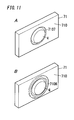
- FIG. 11A and FIG. 11B are enlarged views illustrating primary parts of other examples of the contact device of the present embodiment.
- a recess 7107 in a circular shape is formed in an almost center of the attachment part 710, and the movable contact 4 is situated in the recess 7107 . Therefore, without decreasing the height of the movable contact 4, it is possible to obtain the same effect as in the case where the level difference between the top part of the movable contact 4 (part to be in contact with the fixed contact 3 ) and the surface of the attachment part 710 is decreased.
- the surface close to the fixed contact 3 of the attachment part 710 serves as a protrusion.
- the protrusion is constituted by a periphery of the recess 7107.
- a protrusion 7108 is formed by making part of the attachment part 710 to protrude in the same direction as the protruding direction of the movable contact 4 to be in a ring shape so as to surround the movable contact 4 .
- the volume of the movable contact 4 is not decreased, the arc occurring on the movable contact 4 may easily move from the movable contact 4 to the protrusion (the periphery of the recess 7107 and the protrusion 7108 ).
- the lifetime of contacts can be prolonged.
- the volume of the movable contact 4 is not decreased, there are advantages that the lifetime of contacts with regard to the on and off operation can be maintained and adhesion of the movable contact 4 caused by melting is not likely to occur.
- the protrusion is formed by use of part of the attachment part 710 .
- the protrusion may be a separate part from a remaining part of the attachment part 710 .
- material of facilitating movement of an arc e.g., material with a low work function and material with high thermal conductivity
- a breaking performance can be improved.
- durable material the breaking performance can be more improved.
- the gap (level difference) between the top part of the movable contact 4 and the top part of the protrusion be less than 1 mm.
- the protrusion be placed at a distance of 5 mm or less from an edge (outer periphery) of the movable contact 4. In this case, there is an advantage that an arc easily moves to the protrusion.
- the present embodiment includes the protrusions on both sides with regard to the movable contact 4.
- the number of protrusions may be one or three or more.
- protrusions provided as separate parts may be arranged in circle around the movable contact 4.
- protrusions formed by cutting and raising may be arranged in circle. In these cases, it is possible to obtain the same advantage that an arc is allowed to move to the protrusion while a moving direction of the arc is not limited.
- the present embodiment is described with reference to examples in which the attachment part 710 of the interconnection member 71 and the movable contact 4 are provided as separate parts and the attachment piece 51 and the fixed contact 3 are also provided as separate parts.
- the attachment part 710 of the interconnection member 71 and the movable contact 4 may be formed integrally, and the attachment piece 51 and the fixed contact 3 may be formed integrally.
- the present invention should not be limited to the present embodiment.
- the present embodiment is described with reference to examples in which the protrusions are provided to the movable contact member.
- the protrusions may be provided to at least one of the movable contact member and the fixed contact member. Therefore, the present invention should not be limited to the present embodiment.
- the protrusions may be provided to the fixed contact member or the protrusions may be provided to the movable contact member and the fixed contact member.
- the contact device of the first aspect in accordance with the present invention includes a fixed contact member (the fixed contact 3 and the first terminal 5 ) and a movable contact member (the movable contact 4, the second terminal 6 , and the contact spring 7 ).
- the fixed contact member includes a fixed contact 3.
- the movable contact member includes a movable contact 4 and is movable between a position where the movable contact 4 is in contact with the fixed contact 3 and a position where the movable contact 4 is away from the fixed contact 3 .
- At least one of the fixed contact member and the movable contact member further includes a protrusion which protrudes from a face to which a corresponding contact is provided, in a direction same as a protruding direction of the corresponding contact.
- the protrusion is a separate part from a remaining part of the at least one of the fixed contact member and the movable contact member.
- the protrusion 7100 is formed by cutting and raising part of the at least one of the fixed contact member and the movable contact member.
- the protrusion 7101 to 7103 is formed by causing, part of the at least one of the fixed contact member and the movable contact member, to protrude.
- the protrusion 7104, 7105 is formed by bending part of the at least one of the fixed contact member and the movable contact member.
- the protrusion 7106 is formed by folding an end part of the at least one of the fixed contact member and the movable contact member.
- At least one of the fixed contact member and the movable contact member further includes a recess 7107 in which the corresponding contact (e.g., the movable contact 4 ) is situated.
- the protrusion is constituted by a periphery of the recess 7107 .
- the protrusion 7108 is formed into a ring shape to surround the corresponding contact (e.g., the movable contact 4 ).
- the contact device further includes an armature 8, a driver 2, a contact spring 7, and a card 13 .
- the driver 2 is for driving the armature 8.
- the contact spring 7 is for holding the movable contact 4 so as to allow the movable contact 4 to be in contact with and separate from the fixed contact 3 .
- the card 13 interconnects the armature 8 and the contact spring 7.
- the card 13 is made of resilient material and is fixed to each of the armature 8 and the contact spring 7 .
- the card 13 is more flexible in a direction perpendicular to a contact and separation direction of the movable contact 4 than in the contact and separation direction.
- the card 13 is made of metal.
Landscapes
- Physics & Mathematics (AREA)
- Electromagnetism (AREA)
- Arc-Extinguishing Devices That Are Switches (AREA)
- Contacts (AREA)
Applications Claiming Priority (1)
| Application Number | Priority Date | Filing Date | Title |
|---|---|---|---|
| JP2014098934A JP6655792B2 (ja) | 2014-05-12 | 2014-05-12 | 接点装置 |
Publications (2)
| Publication Number | Publication Date |
|---|---|
| EP2945175A1 true EP2945175A1 (fr) | 2015-11-18 |
| EP2945175B1 EP2945175B1 (fr) | 2018-12-26 |
Family
ID=53174887
Family Applications (1)
| Application Number | Title | Priority Date | Filing Date |
|---|---|---|---|
| EP15167289.6A Active EP2945175B1 (fr) | 2014-05-12 | 2015-05-12 | Dispositif de contact |
Country Status (4)
| Country | Link |
|---|---|
| US (2) | US10032570B2 (fr) |
| EP (1) | EP2945175B1 (fr) |
| JP (1) | JP6655792B2 (fr) |
| CN (2) | CN105097362B (fr) |
Families Citing this family (9)
| Publication number | Priority date | Publication date | Assignee | Title |
|---|---|---|---|---|
| JP6433706B2 (ja) * | 2014-07-28 | 2018-12-05 | 富士通コンポーネント株式会社 | 電磁継電器及びコイル端子 |
| JP6458705B2 (ja) * | 2015-10-29 | 2019-01-30 | オムロン株式会社 | リレー |
| JP2018037287A (ja) * | 2016-08-31 | 2018-03-08 | パナソニックIpマネジメント株式会社 | 電磁リレー |
| JP2019096460A (ja) * | 2017-11-22 | 2019-06-20 | 富士通コンポーネント株式会社 | 電磁継電器 |
| WO2020110912A1 (fr) * | 2018-11-28 | 2020-06-04 | パナソニックIpマネジメント株式会社 | Dispositif de contact |
| DE102018133419A1 (de) * | 2018-12-21 | 2020-06-25 | Johnson Electric Germany GmbH & Co. KG | Festkontaktstückträger für ein Relais und Verfahren zur Einstellung eines Kontaktabstandes |
| JP7036047B2 (ja) * | 2019-01-18 | 2022-03-15 | オムロン株式会社 | リレー |
| JP2021086721A (ja) * | 2019-11-27 | 2021-06-03 | パナソニックIpマネジメント株式会社 | 接点装置 |
| CN119153271B (zh) * | 2024-11-18 | 2025-05-02 | 东莞市中汇瑞德电子股份有限公司 | 一种高压直流继电器辅助触点引出结构形式 |
Citations (6)
| Publication number | Priority date | Publication date | Assignee | Title |
|---|---|---|---|---|
| EP0657907A1 (fr) * | 1993-12-06 | 1995-06-14 | Schneider Electric Sa | Dispositif de rupture de courant d'appareil interrupteur notamment pour contacteur ou contacteur-disjoncteur |
| DE19854625A1 (de) * | 1997-12-01 | 1999-06-02 | Fuji Electric Co Ltd | Kontaktanordnung für elektromagnetisches Schaltschütz |
| EP1085552A1 (fr) * | 1999-09-16 | 2001-03-21 | General Electric Company | Agencement de contacts d'arc |
| DE102007040170A1 (de) * | 2007-08-22 | 2009-02-26 | Siemens Ag | Vorkontakt für ein elektrisches Schaltgerät sowie ein diesen Vorkontakt aufweisendes elektrisches Schaltgerät und Verfahren zur Montage des Vorkontaktes |
| EP2551870A1 (fr) * | 2011-07-27 | 2013-01-30 | Panasonic Corporation | Relais électromagnétique |
| JP2013030308A (ja) | 2011-07-27 | 2013-02-07 | Panasonic Corp | 電磁リレー |
Family Cites Families (19)
| Publication number | Priority date | Publication date | Assignee | Title |
|---|---|---|---|---|
| JPS5049667U (fr) | 1973-09-05 | 1975-05-15 | ||
| JPS5096957U (fr) | 1973-12-19 | 1975-08-13 | ||
| JPS58192419U (ja) * | 1982-06-17 | 1983-12-21 | ミツミ電機株式会社 | 接点取付構造 |
| JPS59196515A (ja) * | 1983-04-21 | 1984-11-07 | 三菱電機株式会社 | 電力開閉装置 |
| JPS6070627A (ja) * | 1983-09-27 | 1985-04-22 | 三菱電機株式会社 | 回路しや断器 |
| JP2658170B2 (ja) | 1988-05-11 | 1997-09-30 | オムロン株式会社 | 開閉器 |
| JPH04118551U (ja) * | 1991-04-09 | 1992-10-23 | オムロン株式会社 | 接点開閉機構 |
| JPH04312715A (ja) * | 1991-04-11 | 1992-11-04 | Fuji Electric Co Ltd | 開閉器の電気接点 |
| JP3383984B2 (ja) * | 1992-05-14 | 2003-03-10 | オムロン株式会社 | 電磁継電器 |
| US5583328A (en) * | 1992-07-02 | 1996-12-10 | Mitsubishi Denki Kabushiki Kaisha | High voltage switch including U-shaped, slitted stationary contact assembly with arc extinguishing/magnetic blowout features |
| JPH06215661A (ja) * | 1993-01-19 | 1994-08-05 | Mitsubishi Electric Corp | 開閉器 |
| EP1313117B1 (fr) * | 2001-11-16 | 2014-06-04 | Abb Ag | Dispositif d'extinction d'arc pour un interrupteur électronique |
| DE102007025537A1 (de) * | 2007-05-31 | 2008-12-04 | Abb Ag | Elektrisches Installationsschaltgerät mit einer Lichtbogenblaseinrichtung |
| JP5120162B2 (ja) * | 2008-09-05 | 2013-01-16 | アンデン株式会社 | 電磁継電器 |
| JP5923932B2 (ja) * | 2011-11-04 | 2016-05-25 | オムロン株式会社 | 接点開閉機構及び電磁継電器 |
| CN104025405B (zh) * | 2011-11-07 | 2017-03-22 | 株式会社自动网络技术研究所 | 电接线盒 |
| EP2620966A1 (fr) * | 2012-01-27 | 2013-07-31 | Johnson Electric S.A. | Agencement de contact pour dispositifs de commutation électrique de grande puissance |
| JP6047909B2 (ja) * | 2012-04-09 | 2016-12-21 | オムロン株式会社 | 開閉器 |
| GB201407705D0 (en) * | 2014-05-01 | 2014-06-18 | Johnson Electric Sa | Improvements in electrical contact sets |
-
2014
- 2014-05-12 JP JP2014098934A patent/JP6655792B2/ja active Active
-
2015
- 2015-05-12 CN CN201510239183.7A patent/CN105097362B/zh active Active
- 2015-05-12 US US14/710,199 patent/US10032570B2/en active Active
- 2015-05-12 EP EP15167289.6A patent/EP2945175B1/fr active Active
- 2015-05-12 CN CN201910131124.6A patent/CN109741995B/zh active Active
-
2018
- 2018-06-21 US US16/015,109 patent/US11011324B2/en active Active
Patent Citations (6)
| Publication number | Priority date | Publication date | Assignee | Title |
|---|---|---|---|---|
| EP0657907A1 (fr) * | 1993-12-06 | 1995-06-14 | Schneider Electric Sa | Dispositif de rupture de courant d'appareil interrupteur notamment pour contacteur ou contacteur-disjoncteur |
| DE19854625A1 (de) * | 1997-12-01 | 1999-06-02 | Fuji Electric Co Ltd | Kontaktanordnung für elektromagnetisches Schaltschütz |
| EP1085552A1 (fr) * | 1999-09-16 | 2001-03-21 | General Electric Company | Agencement de contacts d'arc |
| DE102007040170A1 (de) * | 2007-08-22 | 2009-02-26 | Siemens Ag | Vorkontakt für ein elektrisches Schaltgerät sowie ein diesen Vorkontakt aufweisendes elektrisches Schaltgerät und Verfahren zur Montage des Vorkontaktes |
| EP2551870A1 (fr) * | 2011-07-27 | 2013-01-30 | Panasonic Corporation | Relais électromagnétique |
| JP2013030308A (ja) | 2011-07-27 | 2013-02-07 | Panasonic Corp | 電磁リレー |
Also Published As
| Publication number | Publication date |
|---|---|
| CN109741995A (zh) | 2019-05-10 |
| US20150325385A1 (en) | 2015-11-12 |
| JP2015216052A (ja) | 2015-12-03 |
| CN105097362B (zh) | 2019-03-19 |
| US11011324B2 (en) | 2021-05-18 |
| US20190013158A1 (en) | 2019-01-10 |
| CN105097362A (zh) | 2015-11-25 |
| EP2945175B1 (fr) | 2018-12-26 |
| CN109741995B (zh) | 2020-08-21 |
| JP6655792B2 (ja) | 2020-02-26 |
| US10032570B2 (en) | 2018-07-24 |
Similar Documents
| Publication | Publication Date | Title |
|---|---|---|
| US11011324B2 (en) | Contact device | |
| EP2945179B1 (fr) | Dispositif de contact | |
| EP2945178B1 (fr) | Dispositif de contact | |
| EP2639804B1 (fr) | Dispositif à contact scellé | |
| KR101742872B1 (ko) | 전자 계전기 | |
| CN106057586B (zh) | 触点装置以及电磁继电器 | |
| JP5673878B1 (ja) | 封止接点装置 | |
| US11348750B2 (en) | Relay | |
| JP5741740B1 (ja) | 封止接点装置およびその製造方法 | |
| EP2945174B1 (fr) | Dispositif de contact | |
| JP6119286B2 (ja) | 電磁継電器 | |
| EP3770941A1 (fr) | Relais | |
| CN107251184A (zh) | 线圈端子及具备线圈端子的电磁继电器 | |
| US12412716B2 (en) | Electromagnetic relay | |
| JP2010062042A (ja) | リレー | |
| JP5924398B2 (ja) | 封止接点装置 | |
| JP2021086721A (ja) | 接点装置 |
Legal Events
| Date | Code | Title | Description |
|---|---|---|---|
| PUAI | Public reference made under article 153(3) epc to a published international application that has entered the european phase |
Free format text: ORIGINAL CODE: 0009012 |
|
| AK | Designated contracting states |
Kind code of ref document: A1 Designated state(s): AL AT BE BG CH CY CZ DE DK EE ES FI FR GB GR HR HU IE IS IT LI LT LU LV MC MK MT NL NO PL PT RO RS SE SI SK SM TR |
|
| AX | Request for extension of the european patent |
Extension state: BA ME |
|
| 17P | Request for examination filed |
Effective date: 20160512 |
|
| RBV | Designated contracting states (corrected) |
Designated state(s): AL AT BE BG CH CY CZ DE DK EE ES FI FR GB GR HR HU IE IS IT LI LT LU LV MC MK MT NL NO PL PT RO RS SE SI SK SM TR |
|
| GRAP | Despatch of communication of intention to grant a patent |
Free format text: ORIGINAL CODE: EPIDOSNIGR1 |
|
| STAA | Information on the status of an ep patent application or granted ep patent |
Free format text: STATUS: GRANT OF PATENT IS INTENDED |
|
| RIC1 | Information provided on ipc code assigned before grant |
Ipc: H01H 9/46 20060101AFI20180716BHEP Ipc: H01H 50/54 20060101ALI20180716BHEP Ipc: H01H 50/64 20060101ALI20180716BHEP |
|
| INTG | Intention to grant announced |
Effective date: 20180801 |
|
| GRAS | Grant fee paid |
Free format text: ORIGINAL CODE: EPIDOSNIGR3 |
|
| GRAA | (expected) grant |
Free format text: ORIGINAL CODE: 0009210 |
|
| STAA | Information on the status of an ep patent application or granted ep patent |
Free format text: STATUS: THE PATENT HAS BEEN GRANTED |
|
| AK | Designated contracting states |
Kind code of ref document: B1 Designated state(s): AL AT BE BG CH CY CZ DE DK EE ES FI FR GB GR HR HU IE IS IT LI LT LU LV MC MK MT NL NO PL PT RO RS SE SI SK SM TR |
|
| REG | Reference to a national code |
Ref country code: GB Ref legal event code: FG4D |
|
| REG | Reference to a national code |
Ref country code: CH Ref legal event code: EP |
|
| REG | Reference to a national code |
Ref country code: AT Ref legal event code: REF Ref document number: 1082572 Country of ref document: AT Kind code of ref document: T Effective date: 20190115 |
|
| REG | Reference to a national code |
Ref country code: DE Ref legal event code: R096 Ref document number: 602015022126 Country of ref document: DE |
|
| REG | Reference to a national code |
Ref country code: IE Ref legal event code: FG4D |
|
| PG25 | Lapsed in a contracting state [announced via postgrant information from national office to epo] |
Ref country code: NO Free format text: LAPSE BECAUSE OF FAILURE TO SUBMIT A TRANSLATION OF THE DESCRIPTION OR TO PAY THE FEE WITHIN THE PRESCRIBED TIME-LIMIT Effective date: 20190326 Ref country code: HR Free format text: LAPSE BECAUSE OF FAILURE TO SUBMIT A TRANSLATION OF THE DESCRIPTION OR TO PAY THE FEE WITHIN THE PRESCRIBED TIME-LIMIT Effective date: 20181226 Ref country code: LT Free format text: LAPSE BECAUSE OF FAILURE TO SUBMIT A TRANSLATION OF THE DESCRIPTION OR TO PAY THE FEE WITHIN THE PRESCRIBED TIME-LIMIT Effective date: 20181226 Ref country code: BG Free format text: LAPSE BECAUSE OF FAILURE TO SUBMIT A TRANSLATION OF THE DESCRIPTION OR TO PAY THE FEE WITHIN THE PRESCRIBED TIME-LIMIT Effective date: 20190326 Ref country code: FI Free format text: LAPSE BECAUSE OF FAILURE TO SUBMIT A TRANSLATION OF THE DESCRIPTION OR TO PAY THE FEE WITHIN THE PRESCRIBED TIME-LIMIT Effective date: 20181226 Ref country code: LV Free format text: LAPSE BECAUSE OF FAILURE TO SUBMIT A TRANSLATION OF THE DESCRIPTION OR TO PAY THE FEE WITHIN THE PRESCRIBED TIME-LIMIT Effective date: 20181226 |
|
| REG | Reference to a national code |
Ref country code: NL Ref legal event code: MP Effective date: 20181226 |
|
| REG | Reference to a national code |
Ref country code: LT Ref legal event code: MG4D |
|
| PG25 | Lapsed in a contracting state [announced via postgrant information from national office to epo] |
Ref country code: RS Free format text: LAPSE BECAUSE OF FAILURE TO SUBMIT A TRANSLATION OF THE DESCRIPTION OR TO PAY THE FEE WITHIN THE PRESCRIBED TIME-LIMIT Effective date: 20181226 Ref country code: SE Free format text: LAPSE BECAUSE OF FAILURE TO SUBMIT A TRANSLATION OF THE DESCRIPTION OR TO PAY THE FEE WITHIN THE PRESCRIBED TIME-LIMIT Effective date: 20181226 Ref country code: AL Free format text: LAPSE BECAUSE OF FAILURE TO SUBMIT A TRANSLATION OF THE DESCRIPTION OR TO PAY THE FEE WITHIN THE PRESCRIBED TIME-LIMIT Effective date: 20181226 Ref country code: GR Free format text: LAPSE BECAUSE OF FAILURE TO SUBMIT A TRANSLATION OF THE DESCRIPTION OR TO PAY THE FEE WITHIN THE PRESCRIBED TIME-LIMIT Effective date: 20190327 |
|
| REG | Reference to a national code |
Ref country code: AT Ref legal event code: MK05 Ref document number: 1082572 Country of ref document: AT Kind code of ref document: T Effective date: 20181226 |
|
| PG25 | Lapsed in a contracting state [announced via postgrant information from national office to epo] |
Ref country code: NL Free format text: LAPSE BECAUSE OF FAILURE TO SUBMIT A TRANSLATION OF THE DESCRIPTION OR TO PAY THE FEE WITHIN THE PRESCRIBED TIME-LIMIT Effective date: 20181226 |
|
| PG25 | Lapsed in a contracting state [announced via postgrant information from national office to epo] |
Ref country code: IT Free format text: LAPSE BECAUSE OF FAILURE TO SUBMIT A TRANSLATION OF THE DESCRIPTION OR TO PAY THE FEE WITHIN THE PRESCRIBED TIME-LIMIT Effective date: 20181226 Ref country code: PL Free format text: LAPSE BECAUSE OF FAILURE TO SUBMIT A TRANSLATION OF THE DESCRIPTION OR TO PAY THE FEE WITHIN THE PRESCRIBED TIME-LIMIT Effective date: 20181226 Ref country code: ES Free format text: LAPSE BECAUSE OF FAILURE TO SUBMIT A TRANSLATION OF THE DESCRIPTION OR TO PAY THE FEE WITHIN THE PRESCRIBED TIME-LIMIT Effective date: 20181226 Ref country code: CZ Free format text: LAPSE BECAUSE OF FAILURE TO SUBMIT A TRANSLATION OF THE DESCRIPTION OR TO PAY THE FEE WITHIN THE PRESCRIBED TIME-LIMIT Effective date: 20181226 Ref country code: PT Free format text: LAPSE BECAUSE OF FAILURE TO SUBMIT A TRANSLATION OF THE DESCRIPTION OR TO PAY THE FEE WITHIN THE PRESCRIBED TIME-LIMIT Effective date: 20190426 |
|
| PG25 | Lapsed in a contracting state [announced via postgrant information from national office to epo] |
Ref country code: SM Free format text: LAPSE BECAUSE OF FAILURE TO SUBMIT A TRANSLATION OF THE DESCRIPTION OR TO PAY THE FEE WITHIN THE PRESCRIBED TIME-LIMIT Effective date: 20181226 Ref country code: EE Free format text: LAPSE BECAUSE OF FAILURE TO SUBMIT A TRANSLATION OF THE DESCRIPTION OR TO PAY THE FEE WITHIN THE PRESCRIBED TIME-LIMIT Effective date: 20181226 Ref country code: RO Free format text: LAPSE BECAUSE OF FAILURE TO SUBMIT A TRANSLATION OF THE DESCRIPTION OR TO PAY THE FEE WITHIN THE PRESCRIBED TIME-LIMIT Effective date: 20181226 Ref country code: IS Free format text: LAPSE BECAUSE OF FAILURE TO SUBMIT A TRANSLATION OF THE DESCRIPTION OR TO PAY THE FEE WITHIN THE PRESCRIBED TIME-LIMIT Effective date: 20190426 Ref country code: SK Free format text: LAPSE BECAUSE OF FAILURE TO SUBMIT A TRANSLATION OF THE DESCRIPTION OR TO PAY THE FEE WITHIN THE PRESCRIBED TIME-LIMIT Effective date: 20181226 |
|
| REG | Reference to a national code |
Ref country code: DE Ref legal event code: R097 Ref document number: 602015022126 Country of ref document: DE |
|
| PG25 | Lapsed in a contracting state [announced via postgrant information from national office to epo] |
Ref country code: DK Free format text: LAPSE BECAUSE OF FAILURE TO SUBMIT A TRANSLATION OF THE DESCRIPTION OR TO PAY THE FEE WITHIN THE PRESCRIBED TIME-LIMIT Effective date: 20181226 Ref country code: AT Free format text: LAPSE BECAUSE OF FAILURE TO SUBMIT A TRANSLATION OF THE DESCRIPTION OR TO PAY THE FEE WITHIN THE PRESCRIBED TIME-LIMIT Effective date: 20181226 |
|
| PLBE | No opposition filed within time limit |
Free format text: ORIGINAL CODE: 0009261 |
|
| STAA | Information on the status of an ep patent application or granted ep patent |
Free format text: STATUS: NO OPPOSITION FILED WITHIN TIME LIMIT |
|
| 26N | No opposition filed |
Effective date: 20190927 |
|
| REG | Reference to a national code |
Ref country code: CH Ref legal event code: PL |
|
| GBPC | Gb: european patent ceased through non-payment of renewal fee |
Effective date: 20190512 |
|
| PG25 | Lapsed in a contracting state [announced via postgrant information from national office to epo] |
Ref country code: LI Free format text: LAPSE BECAUSE OF NON-PAYMENT OF DUE FEES Effective date: 20190531 Ref country code: CH Free format text: LAPSE BECAUSE OF NON-PAYMENT OF DUE FEES Effective date: 20190531 Ref country code: MC Free format text: LAPSE BECAUSE OF FAILURE TO SUBMIT A TRANSLATION OF THE DESCRIPTION OR TO PAY THE FEE WITHIN THE PRESCRIBED TIME-LIMIT Effective date: 20181226 |
|
| REG | Reference to a national code |
Ref country code: BE Ref legal event code: MM Effective date: 20190531 |
|
| PG25 | Lapsed in a contracting state [announced via postgrant information from national office to epo] |
Ref country code: LU Free format text: LAPSE BECAUSE OF NON-PAYMENT OF DUE FEES Effective date: 20190512 Ref country code: SI Free format text: LAPSE BECAUSE OF FAILURE TO SUBMIT A TRANSLATION OF THE DESCRIPTION OR TO PAY THE FEE WITHIN THE PRESCRIBED TIME-LIMIT Effective date: 20181226 |
|
| PG25 | Lapsed in a contracting state [announced via postgrant information from national office to epo] |
Ref country code: TR Free format text: LAPSE BECAUSE OF FAILURE TO SUBMIT A TRANSLATION OF THE DESCRIPTION OR TO PAY THE FEE WITHIN THE PRESCRIBED TIME-LIMIT Effective date: 20181226 |
|
| PG25 | Lapsed in a contracting state [announced via postgrant information from national office to epo] |
Ref country code: IE Free format text: LAPSE BECAUSE OF NON-PAYMENT OF DUE FEES Effective date: 20190512 Ref country code: GB Free format text: LAPSE BECAUSE OF NON-PAYMENT OF DUE FEES Effective date: 20190512 |
|
| PG25 | Lapsed in a contracting state [announced via postgrant information from national office to epo] |
Ref country code: BE Free format text: LAPSE BECAUSE OF NON-PAYMENT OF DUE FEES Effective date: 20190531 |
|
| PG25 | Lapsed in a contracting state [announced via postgrant information from national office to epo] |
Ref country code: FR Free format text: LAPSE BECAUSE OF NON-PAYMENT OF DUE FEES Effective date: 20190531 |
|
| PG25 | Lapsed in a contracting state [announced via postgrant information from national office to epo] |
Ref country code: CY Free format text: LAPSE BECAUSE OF FAILURE TO SUBMIT A TRANSLATION OF THE DESCRIPTION OR TO PAY THE FEE WITHIN THE PRESCRIBED TIME-LIMIT Effective date: 20181226 |
|
| PG25 | Lapsed in a contracting state [announced via postgrant information from national office to epo] |
Ref country code: MT Free format text: LAPSE BECAUSE OF FAILURE TO SUBMIT A TRANSLATION OF THE DESCRIPTION OR TO PAY THE FEE WITHIN THE PRESCRIBED TIME-LIMIT Effective date: 20181226 Ref country code: HU Free format text: LAPSE BECAUSE OF FAILURE TO SUBMIT A TRANSLATION OF THE DESCRIPTION OR TO PAY THE FEE WITHIN THE PRESCRIBED TIME-LIMIT; INVALID AB INITIO Effective date: 20150512 |
|
| PG25 | Lapsed in a contracting state [announced via postgrant information from national office to epo] |
Ref country code: MK Free format text: LAPSE BECAUSE OF FAILURE TO SUBMIT A TRANSLATION OF THE DESCRIPTION OR TO PAY THE FEE WITHIN THE PRESCRIBED TIME-LIMIT Effective date: 20181226 |
|
| PGFP | Annual fee paid to national office [announced via postgrant information from national office to epo] |
Ref country code: DE Payment date: 20250521 Year of fee payment: 11 |