EP2945242A2 - Éolienne dotée d'une protection améliorée contre les surtensions - Google Patents
Éolienne dotée d'une protection améliorée contre les surtensions Download PDFInfo
- Publication number
- EP2945242A2 EP2945242A2 EP15167549.3A EP15167549A EP2945242A2 EP 2945242 A2 EP2945242 A2 EP 2945242A2 EP 15167549 A EP15167549 A EP 15167549A EP 2945242 A2 EP2945242 A2 EP 2945242A2
- Authority
- EP
- European Patent Office
- Prior art keywords
- voltage
- overvoltage
- plant according
- wind energy
- energy plant
- Prior art date
- Legal status (The legal status is an assumption and is not a legal conclusion. Google has not performed a legal analysis and makes no representation as to the accuracy of the status listed.)
- Granted
Links
Images


Classifications
-
- H—ELECTRICITY
- H02—GENERATION; CONVERSION OR DISTRIBUTION OF ELECTRIC POWER
- H02J—ELECTRIC POWER NETWORKS; CIRCUIT ARRANGEMENTS OR SYSTEMS FOR SUPPLYING OR DISTRIBUTING ELECTRIC POWER; SYSTEMS FOR STORING ELECTRIC ENERGY
- H02J3/00—Circuit arrangements for AC mains or AC distribution networks
- H02J3/38—Arrangements for feeding a single network from two or more generators or sources in parallel; Arrangements for feeding already energised networks from additional generators or sources in parallel
- H02J3/46—Controlling the sharing of generated power between the generators, sources or networks
- H02J3/48—Controlling the sharing of active power
-
- F—MECHANICAL ENGINEERING; LIGHTING; HEATING; WEAPONS; BLASTING
- F03—MACHINES OR ENGINES FOR LIQUIDS; WIND, SPRING, OR WEIGHT MOTORS; PRODUCING MECHANICAL POWER OR A REACTIVE PROPULSIVE THRUST, NOT OTHERWISE PROVIDED FOR
- F03D—WIND MOTORS
- F03D9/00—Adaptations of wind motors for special use; Combinations of wind motors with apparatus driven thereby; Wind motors specially adapted for installation in particular locations
- F03D9/20—Wind motors characterised by the driven apparatus
- F03D9/25—Wind motors characterised by the driven apparatus the apparatus being an electrical generator
- F03D9/255—Wind motors characterised by the driven apparatus the apparatus being an electrical generator connected to electrical distribution networks; Arrangements therefor
-
- F—MECHANICAL ENGINEERING; LIGHTING; HEATING; WEAPONS; BLASTING
- F03—MACHINES OR ENGINES FOR LIQUIDS; WIND, SPRING, OR WEIGHT MOTORS; PRODUCING MECHANICAL POWER OR A REACTIVE PROPULSIVE THRUST, NOT OTHERWISE PROVIDED FOR
- F03D—WIND MOTORS
- F03D9/00—Adaptations of wind motors for special use; Combinations of wind motors with apparatus driven thereby; Wind motors specially adapted for installation in particular locations
- F03D9/20—Wind motors characterised by the driven apparatus
- F03D9/25—Wind motors characterised by the driven apparatus the apparatus being an electrical generator
- F03D9/255—Wind motors characterised by the driven apparatus the apparatus being an electrical generator connected to electrical distribution networks; Arrangements therefor
- F03D9/257—Wind motors characterised by the driven apparatus the apparatus being an electrical generator connected to electrical distribution networks; Arrangements therefor the wind motor being part of a wind farm
-
- H—ELECTRICITY
- H02—GENERATION; CONVERSION OR DISTRIBUTION OF ELECTRIC POWER
- H02H—EMERGENCY PROTECTIVE CIRCUIT ARRANGEMENTS
- H02H7/00—Emergency protective circuit arrangements specially adapted for specific types of electric machines or apparatus or for sectionalised protection of cable or line systems, and effecting automatic switching in the event of an undesired change from normal working conditions
- H02H7/10—Emergency protective circuit arrangements specially adapted for specific types of electric machines or apparatus or for sectionalised protection of cable or line systems, and effecting automatic switching in the event of an undesired change from normal working conditions for converters; for rectifiers
- H02H7/12—Emergency protective circuit arrangements specially adapted for specific types of electric machines or apparatus or for sectionalised protection of cable or line systems, and effecting automatic switching in the event of an undesired change from normal working conditions for converters; for rectifiers for static converters or rectifiers
- H02H7/1216—Emergency protective circuit arrangements specially adapted for specific types of electric machines or apparatus or for sectionalised protection of cable or line systems, and effecting automatic switching in the event of an undesired change from normal working conditions for converters; for rectifiers for static converters or rectifiers for AC-AC converters
-
- H—ELECTRICITY
- H02—GENERATION; CONVERSION OR DISTRIBUTION OF ELECTRIC POWER
- H02J—ELECTRIC POWER NETWORKS; CIRCUIT ARRANGEMENTS OR SYSTEMS FOR SUPPLYING OR DISTRIBUTING ELECTRIC POWER; SYSTEMS FOR STORING ELECTRIC ENERGY
- H02J3/00—Circuit arrangements for AC mains or AC distribution networks
- H02J3/12—Arrangements for adjusting voltage in AC networks by changing a characteristic of the network load
-
- H—ELECTRICITY
- H02—GENERATION; CONVERSION OR DISTRIBUTION OF ELECTRIC POWER
- H02J—ELECTRIC POWER NETWORKS; CIRCUIT ARRANGEMENTS OR SYSTEMS FOR SUPPLYING OR DISTRIBUTING ELECTRIC POWER; SYSTEMS FOR STORING ELECTRIC ENERGY
- H02J3/00—Circuit arrangements for AC mains or AC distribution networks
- H02J3/18—Arrangements for adjusting, eliminating or compensating reactive power in networks
- H02J3/1885—Arrangements for adjusting, eliminating or compensating reactive power in networks using rotating AC generators, e.g. synchronous generators
-
- H—ELECTRICITY
- H02—GENERATION; CONVERSION OR DISTRIBUTION OF ELECTRIC POWER
- H02J—ELECTRIC POWER NETWORKS; CIRCUIT ARRANGEMENTS OR SYSTEMS FOR SUPPLYING OR DISTRIBUTING ELECTRIC POWER; SYSTEMS FOR STORING ELECTRIC ENERGY
- H02J3/00—Circuit arrangements for AC mains or AC distribution networks
- H02J3/38—Arrangements for feeding a single network from two or more generators or sources in parallel; Arrangements for feeding already energised networks from additional generators or sources in parallel
- H02J3/381—Dispersed generators
-
- H—ELECTRICITY
- H02—GENERATION; CONVERSION OR DISTRIBUTION OF ELECTRIC POWER
- H02M—APPARATUS FOR CONVERSION BETWEEN AC AND AC, BETWEEN AC AND DC, OR BETWEEN DC AND DC, AND FOR USE WITH MAINS OR SIMILAR POWER SUPPLY SYSTEMS; CONVERSION OF DC OR AC INPUT POWER INTO SURGE OUTPUT POWER; CONTROL OR REGULATION THEREOF
- H02M1/00—Details of apparatus for conversion
- H02M1/32—Means for protecting converters other than automatic disconnection
-
- H—ELECTRICITY
- H02—GENERATION; CONVERSION OR DISTRIBUTION OF ELECTRIC POWER
- H02M—APPARATUS FOR CONVERSION BETWEEN AC AND AC, BETWEEN AC AND DC, OR BETWEEN DC AND DC, AND FOR USE WITH MAINS OR SIMILAR POWER SUPPLY SYSTEMS; CONVERSION OF DC OR AC INPUT POWER INTO SURGE OUTPUT POWER; CONTROL OR REGULATION THEREOF
- H02M5/00—Conversion of AC power input into AC power output, e.g. for change of voltage, for change of frequency, for change of number of phases
- H02M5/40—Conversion of AC power input into AC power output, e.g. for change of voltage, for change of frequency, for change of number of phases with intermediate conversion into DC
- H02M5/42—Conversion of AC power input into AC power output, e.g. for change of voltage, for change of frequency, for change of number of phases with intermediate conversion into DC by static converters
- H02M5/44—Conversion of AC power input into AC power output, e.g. for change of voltage, for change of frequency, for change of number of phases with intermediate conversion into DC by static converters using discharge tubes or semiconductor devices to convert the intermediate DC into AC
- H02M5/453—Conversion of AC power input into AC power output, e.g. for change of voltage, for change of frequency, for change of number of phases with intermediate conversion into DC by static converters using discharge tubes or semiconductor devices to convert the intermediate DC into AC using devices of a triode or transistor type requiring continuous application of a control signal
- H02M5/458—Conversion of AC power input into AC power output, e.g. for change of voltage, for change of frequency, for change of number of phases with intermediate conversion into DC by static converters using discharge tubes or semiconductor devices to convert the intermediate DC into AC using devices of a triode or transistor type requiring continuous application of a control signal using semiconductor devices only
-
- H—ELECTRICITY
- H02—GENERATION; CONVERSION OR DISTRIBUTION OF ELECTRIC POWER
- H02P—CONTROL OR REGULATION OF ELECTRIC MOTORS, ELECTRIC GENERATORS OR DYNAMO-ELECTRIC CONVERTERS; CONTROLLING TRANSFORMERS, REACTORS OR CHOKE COILS
- H02P9/00—Arrangements for controlling electric generators for the purpose of obtaining a desired output
- H02P9/02—Details of the control
-
- H—ELECTRICITY
- H02—GENERATION; CONVERSION OR DISTRIBUTION OF ELECTRIC POWER
- H02J—ELECTRIC POWER NETWORKS; CIRCUIT ARRANGEMENTS OR SYSTEMS FOR SUPPLYING OR DISTRIBUTING ELECTRIC POWER; SYSTEMS FOR STORING ELECTRIC ENERGY
- H02J2101/00—Supply or distribution of decentralised, dispersed or local electric power generation
- H02J2101/20—Dispersed power generation using renewable energy sources
- H02J2101/28—Wind energy
-
- H—ELECTRICITY
- H02—GENERATION; CONVERSION OR DISTRIBUTION OF ELECTRIC POWER
- H02M—APPARATUS FOR CONVERSION BETWEEN AC AND AC, BETWEEN AC AND DC, OR BETWEEN DC AND DC, AND FOR USE WITH MAINS OR SIMILAR POWER SUPPLY SYSTEMS; CONVERSION OF DC OR AC INPUT POWER INTO SURGE OUTPUT POWER; CONTROL OR REGULATION THEREOF
- H02M1/00—Details of apparatus for conversion
- H02M1/0064—Magnetic structures combining different functions, e.g. storage, filtering or transformation
-
- H—ELECTRICITY
- H02—GENERATION; CONVERSION OR DISTRIBUTION OF ELECTRIC POWER
- H02M—APPARATUS FOR CONVERSION BETWEEN AC AND AC, BETWEEN AC AND DC, OR BETWEEN DC AND DC, AND FOR USE WITH MAINS OR SIMILAR POWER SUPPLY SYSTEMS; CONVERSION OF DC OR AC INPUT POWER INTO SURGE OUTPUT POWER; CONTROL OR REGULATION THEREOF
- H02M1/00—Details of apparatus for conversion
- H02M1/32—Means for protecting converters other than automatic disconnection
- H02M1/325—Means for protecting converters other than automatic disconnection with means for allowing continuous operation despite a fault, i.e. fault tolerant converters
-
- H—ELECTRICITY
- H02—GENERATION; CONVERSION OR DISTRIBUTION OF ELECTRIC POWER
- H02M—APPARATUS FOR CONVERSION BETWEEN AC AND AC, BETWEEN AC AND DC, OR BETWEEN DC AND DC, AND FOR USE WITH MAINS OR SIMILAR POWER SUPPLY SYSTEMS; CONVERSION OF DC OR AC INPUT POWER INTO SURGE OUTPUT POWER; CONTROL OR REGULATION THEREOF
- H02M1/00—Details of apparatus for conversion
- H02M1/42—Circuits or arrangements for compensating for or adjusting power factor in converters or inverters
-
- Y—GENERAL TAGGING OF NEW TECHNOLOGICAL DEVELOPMENTS; GENERAL TAGGING OF CROSS-SECTIONAL TECHNOLOGIES SPANNING OVER SEVERAL SECTIONS OF THE IPC; TECHNICAL SUBJECTS COVERED BY FORMER USPC CROSS-REFERENCE ART COLLECTIONS [XRACs] AND DIGESTS
- Y02—TECHNOLOGIES OR APPLICATIONS FOR MITIGATION OR ADAPTATION AGAINST CLIMATE CHANGE
- Y02B—CLIMATE CHANGE MITIGATION TECHNOLOGIES RELATED TO BUILDINGS, e.g. HOUSING, HOUSE APPLIANCES OR RELATED END-USER APPLICATIONS
- Y02B70/00—Technologies for an efficient end-user side electric power management and consumption
- Y02B70/10—Technologies improving the efficiency by using switched-mode power supplies [SMPS], i.e. efficient power electronics conversion e.g. power factor correction or reduction of losses in power supplies or efficient standby modes
-
- Y—GENERAL TAGGING OF NEW TECHNOLOGICAL DEVELOPMENTS; GENERAL TAGGING OF CROSS-SECTIONAL TECHNOLOGIES SPANNING OVER SEVERAL SECTIONS OF THE IPC; TECHNICAL SUBJECTS COVERED BY FORMER USPC CROSS-REFERENCE ART COLLECTIONS [XRACs] AND DIGESTS
- Y02—TECHNOLOGIES OR APPLICATIONS FOR MITIGATION OR ADAPTATION AGAINST CLIMATE CHANGE
- Y02E—REDUCTION OF GREENHOUSE GAS [GHG] EMISSIONS, RELATED TO ENERGY GENERATION, TRANSMISSION OR DISTRIBUTION
- Y02E10/00—Energy generation through renewable energy sources
- Y02E10/70—Wind energy
- Y02E10/72—Wind turbines with rotation axis in wind direction
-
- Y—GENERAL TAGGING OF NEW TECHNOLOGICAL DEVELOPMENTS; GENERAL TAGGING OF CROSS-SECTIONAL TECHNOLOGIES SPANNING OVER SEVERAL SECTIONS OF THE IPC; TECHNICAL SUBJECTS COVERED BY FORMER USPC CROSS-REFERENCE ART COLLECTIONS [XRACs] AND DIGESTS
- Y02—TECHNOLOGIES OR APPLICATIONS FOR MITIGATION OR ADAPTATION AGAINST CLIMATE CHANGE
- Y02E—REDUCTION OF GREENHOUSE GAS [GHG] EMISSIONS, RELATED TO ENERGY GENERATION, TRANSMISSION OR DISTRIBUTION
- Y02E10/00—Energy generation through renewable energy sources
- Y02E10/70—Wind energy
- Y02E10/76—Power conversion electric or electronic aspects
-
- Y—GENERAL TAGGING OF NEW TECHNOLOGICAL DEVELOPMENTS; GENERAL TAGGING OF CROSS-SECTIONAL TECHNOLOGIES SPANNING OVER SEVERAL SECTIONS OF THE IPC; TECHNICAL SUBJECTS COVERED BY FORMER USPC CROSS-REFERENCE ART COLLECTIONS [XRACs] AND DIGESTS
- Y02—TECHNOLOGIES OR APPLICATIONS FOR MITIGATION OR ADAPTATION AGAINST CLIMATE CHANGE
- Y02E—REDUCTION OF GREENHOUSE GAS [GHG] EMISSIONS, RELATED TO ENERGY GENERATION, TRANSMISSION OR DISTRIBUTION
- Y02E40/00—Technologies for an efficient electrical power generation, transmission or distribution
- Y02E40/30—Reactive power compensation
Definitions
- Wind turbine with a wind rotor, a generator which is driven by the wind rotor, and a converter for generating electrical energy, which is discharged via a connecting line with an inductively acting line choke to a network, wherein an overvoltage protection device is provided.
- the invention has for its object to provide an improved overvoltage protection device, which achieves higher overvoltage strengths in a more efficient manner.
- an overvoltage protection device In a wind turbine with a wind rotor, a generator, which is driven by the wind rotor, and a converter, wherein the generator and the converter are designed to generate electrical energy, which is delivered via a connecting line with an inductively acting line choke to a network, an overvoltage protection device is provided according to the invention, the overvoltage protection device is designed such that it comprises a plurality of different active modules, which are designed so that they each cause a decrease in the voltage at the output of the inverter, a switching matrix, which the different active modules in the overvoltage range switches on and off, and a selector with an overvoltage classifier, which is adapted to determine depending on the overvoltage an overvoltage range and to select a predetermined level to control the switching matrix such that successively some Wirkmo dule, wherein the overvoltage classifier defines a plurality of overvoltage areas, in which the selector sets each different switching groups.
- Overvoltage ranges are understood to be voltage ranges above the nominal voltage, which extend over predetermined sections in each case. For example, a first overvoltage range between 116 and 130% of the mains voltage, a second overvoltage range between 130 and 145%, and finally a third overvoltage range between 145 and 170%.
- active modules is understood to mean those structural units which in each case cause an increase in the overvoltage resistance of the wind power plant itself.
- the invention makes it possible to combine different approaches to increase the overvoltage resistance. This results in a combinatorial effect, which makes it possible to cope with even higher requirements for the surge voltage with voltage peaks, up to, for example, 170% of the mains voltage on this basis, without the need for a performance higher design of the inverter would be required. So you can continue to use the previously used inverter. As a result, considerable effort is saved.
- the invention achieves this through the innovative interaction of various measures, some of which are known per se. In the prior art, this is not an example.
- the invention thus not only achieves a high overvoltage tolerance, but also makes it possible to leave the essential core components of the wind energy plant, in particular its converter, unchanged.
- she allows one graded response depending on the severity of the overvoltage situation (overvoltage range).
- the behavior of the wind turbine is transparent to the grid, ie from the network's point of view, the wind turbine behaves completely unobtrusive, as if it has the required dielectric strength due to a higher designed inverter. Overall, this results in a much more effective protection of the wind turbine against overvoltages, compared with the previously either insufficient measures or very expensive measures, such as a considerable over-interpretation of the inverter.
- the selector is designed so that at least two, preferably three different overvoltage stages are switchable.
- This can be provided as the first overvoltage range of the previously used overvoltage range of 116% (end of the tolerance band to the rated voltage) up to 130%.
- This is followed by an extended overvoltage range of 130% to 145%.
- This is followed by a survival area, in which the self-protection of the wind turbine has priority, to about 170%.
- the selector and the switch matrix are combined. This allows a particularly compact design. An example of this is an embodiment as a tap-changer.
- one of the active modules is designed as a reduction element for reducing the delivered active power of the wind energy plant, and specifically only from at least a second overvoltage range. This ensures that at higher overvoltages (in the extended overvoltage range or even only in the survival range) the effective power delivered by the wind energy plant is reduced.
- the inverter thus relieved of the output of active power can then deliver correspondingly more reactive power. This is preferably done gradually.
- a current statics is expediently implemented, wherein the delivered active current is increasingly reduced with increasing voltage.
- variable limiter is understood here to mean that, depending on the overvoltage range, a permissible upper limit for the capacitive reactive power output is defined and lowered with increasing voltage.
- the limiter preferably has a limitation statics. Thus, when overvoltage occurs, the output of capacitive reactive power can be lowered to zero (or another adjustable sub-value). This measure is used to reduce the voltage on the line-side inverter.
- another of the active modules has an overcurrent control which sets an increased inductive reactive power output, which is preferably above the rated reactive power output.
- the active module makes use of the knowledge that by delivering inductive reactive power, a voltage reduction can be achieved.
- the extent thus achieved depends on the dimensions of the choke and the transformer in the connecting line.
- the throttle is sized so that the flow of current through it at the top of the extended Overvoltage range is a maximum of 1.6 times, preferably at most 1.1 times the rated current of the grid-side inverter.
- the increased inductive reactive power can be dimensioned such that it amounts to at least twice, preferably at least four times, the rated reactive power output.
- One of the active modules is preferably designed as a voltage statics for a nominal voltage shifter in a DC link of the inverter. This allows the selector to raise the DC link voltage in the inverter in the desired overvoltage range. Preferably, the increase is disproportionate, i. if the boost occurs, it will be done on a larger scale than the increase in line voltage. By raising the intermediate circuit voltage is achieved that the output from the grid-side inverter of the inverter voltage to the network can also increase. The wind turbine can thus adapt to the increased voltage in the network.
- one of the active modules is designed as an overmodulation element, which increases the voltage delivered by the converter, more precisely its line-side inverter.
- the output voltage of the network-side inverter can be further increased, in particular in high voltage ranges (survival ranges), by short-time overmodulation, and thus adapted to the increased mains voltage.
- This has proven to be overmodulation degrees, which can cause at least 5%, preferably up to 7% increase in voltage.
- the harmonic distortion is set to a value of at most 20%.
- a voltage statics is preferably provided. It is expediently divided into several areas. This can be determined depending on the overvoltage range, a different behavior. Advantageously, this already takes place in the first overvoltage range, to a disproportionate extent. For this purpose, a characteristic gradient greater than one (disproportionately) is implemented in the voltage statics. Preferably, it is part of a ramp function, which then has an increased constant value in another overvoltage range.
- the reduction member further comprises a control output for activating a chopper on the DC link.
- Activation can be direct or indirect.
- directly is meant that the reduction member does not directly activate the chopper, but rather switching thresholds or limit values of the chopper control present in itself are modified and thus its application behavior is changed in the desired manner.
- the reduction element can additionally dissipate power into the chopper, at least in the short term, so as to relieve the intermediate circuit. The current load of the grid-side inverter is thus further reduced or it can deliver correspondingly more reactive current and thus reactive power.
- a maximum voltage is reduced. This allows a more favorable magnetic design of the transformer of the wind turbine. Furthermore, cooperation with the overvoltage classifier is preferably provided in such a way that, with the maximum voltage lowered, the classification takes place with correspondingly reduced values. Thus, the classification is tracked in terms of the reduced maximum voltage, and so continues to ensure a sensitive graded response.
- the plant transformer in the connecting line of the wind turbine is dimensioned so that it is magnetically saturated at mains frequencies below a nominal mains frequency in the overvoltage range.
- a transformer designed in this way it is achieved that it behaves like an inductive choke in the event of overvoltages due to additional saturation current, and thus automatically acts as a passive voltage-reducing effect.
- the transformer thus intervenes automatically stabilizing. Because of its considerable inductance, a considerable contribution to the voltage reduction is thus achieved without additional effort.
- the starting point for its voltage-lowering effect due to the frequency dependence is not exactly defined, but this is not serious in view of the advantages achieved thereby.
- the plant transformer is designed for a lowered main field voltage.
- the plant transformer can be made smaller, so that it is ultimately even cheaper.
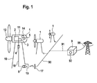
- a in the embodiment according to FIG. 1 represented wind farm comprises a plurality of wind turbines 1, which are each connected via a connecting line 19 with a plant transformer 8 to an internal collection network 90. Via a main line 91, the collecting network 90 is connected via a parking transformer 92 to a high-voltage power transmission network 99.
- the wind farm is controlled in its entirety by a Parkmaster 9.
- the wind turbine 1 according to the exemplary embodiment of the invention comprises a tower 10, on the upper end of which a gondola 11 is pivotably arranged in the azimuth direction. At one end face of a wind rotor 12 is rotatably mounted, which via a rotor shaft (not shown) drives a generator 2 for generating electrical energy. This is connected to a converter 3 for delivering the generated electrical energy via a Low-voltage connection line 18 which is connected to the plant transformer 8 and comprises a mains choke 4.
- the mains choke 4 is preferably designed as an LCL filter.
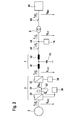
- the electrical function blocks of the wind turbine 1 are visualized. From the generator 2 electrical energy is generated and fed via a network-side inverter 30 of the inverter 3 in a DC voltage intermediate circuit 31.
- the DC voltage intermediate circuit 31 has a capacitor (not shown) as an energy store.
- a chopper 32 is arranged in a conventional manner to the DC voltage intermediate circuit 31, which can be controlled optionally and serves to reduce the DC voltage supplied in the DC intermediate circuit 31.
- the voltage in the DC voltage intermediate circuit 31 is referred to as U DC .
- a network-side inverter 33 is provided, to which the reactor 4 is connected.
- the voltage at the output of the grid-side inverter 33 of the inverter 3 is referred to as U LSI and the current flowing from the grid-side inverter 33 into the line choke 4 current as I ' LSI .
- the line reactor 4 is designed as an LCL line filter and comprises two inductors, a converter-side inductor 41 and a line-side inductor 42. Between them, a filter capacitor 43 is connected. At the output of the line choke 4, a low-voltage circuit breaker 40 is arranged. The current flowing through it in the closed state is referred to as I LSI .
- a connection point 44 is provided, which is used to supply the electrical components of the wind turbine 1 including its controller 14 is used (the so-called. Personal use). On the network side of this connection point 44 of the machine transformer 8 of the wind turbine 1 is connected.
- connection point 44 for the personal use and the machine transformer 8 through a low-voltage connection line 18 is referred to as I LV , and the voltage prevailing there as U LV .
- I LV The current flowing between the connection point 44 for the personal use and the machine transformer 8 through a low-voltage connection line 18 is referred to as I LV , and the voltage prevailing there as U LV .
- U LV the voltage prevailing there as U MV .
- the controller 14 of the wind turbine comprises an overvoltage protection device 5, which serves to protect the wind turbine 1 in the event of voltage disturbances in the network, in particular when overvoltages occur, from harmful high voltages and their negative effects.
- the overvoltage protection device 5 comprises a plurality of active modules 61, 62, 63, 64, 65, 66, which each contribute to a reduction of a voltage increase in different ways.
- the active modules 61-66 are designed so that, in the case of a network-side rise in the mean voltage U MV , and correspondingly also the voltage U LV applied in the low-voltage connection line 18, a slight increase in voltage occurs in the area of the converter 3 of the wind energy plant, so that the latter is too close high voltages is protected. decisive is here for the voltage at the output of the inverter 33, hence U LSI .
- the overvoltage protection device 5 comprises a switching matrix 6, with which the active modules 61-66 are linked.
- the switching matrix 6 switches depending on the switching state, the different active modules or from.
- a selector 7 with an overvoltage classifier 70 is provided.
- the overvoltage classifier 70 is connected to a voltage sensor 17, which measures the voltage in the connection line 19 of the wind turbine 1 (a measurement on the low voltage connection line 18 is also possible). Values for overvoltage ranges I, II, III are set at the overvoltage classifier.
- the overvoltage classifier is designed to determine, depending on the voltage measured by the sensor 17, whether there is an overvoltage, ie a voltage above the rated voltage of the network plus a predetermined tolerance range.
- the predetermined tolerance range should be a value of up to + 16% of the mains voltage.
- the overvoltage classifier 70 now determines, depending on whether the mains voltage is between 116 and 130% of the nominal voltage, between 130 and 145% of the rated voltage, or between 145 and 170% of the nominal voltage, which stage of the selector 7 he controls.
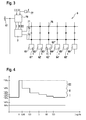
- the selector 7 now controls depending on which of its stages were controlled by the Sprintsklassifikator 70, switching groups 71, 72, 73, which corresponding connection or disconnection signals via the switching matrix. 6 to the active modules 61-66. Thus, it can be determined via the selector 7 and the switching matrix 6, which of the active modules are activated or deactivated in which overvoltage range. This can be set freely via the switching matrix 6. In this case, it is the case that in a first overvoltage range (between 116% and 130% of the nominal voltage) the switching group 71 is activated. This case will be referred to as overvoltage range I below.
- overvoltage range II In the case of an overvoltage in the range between 130 and 145%, the switching group 72 is actuated, this case is referred to as overvoltage range II. If the voltage is in the range between 145% and 170%, the switching group 73 is actuated and this case is referred to as overvoltage range III.
- the overvoltage areas are in FIG. 4 shown and in the respective overvoltage ranges, taking into account the set switching groups 71-73 resulting switching states for the active modules 61-66 are in FIG. 5 shown.
- the active modules will be described in more detail with regard to their construction and their mode of operation as well as their effect on the electrical parameters, in particular the voltage and currents.
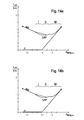
- the active module 61 is designed as a reduction member and designed to reduce the output of the inverter 3 active power at critical overvoltage (ie in the overvoltage range III).
- a voltage statics 61 ' is implemented, which is designed as a negative proportional control. This means that above an adjustable threshold value, the active power output by the converter 3 is reduced with increasing voltage. This is where the tension comes the medium voltage level U MV on.
- the proportional control in the voltage statics 61 ' is set so that when reaching the upper end of the overvoltage range III at a value of 170% of the rated voltage, the active power feed is reduced to zero (see point X in FIG Fig. 6a ).
- the reduction starts at a voltage value U Z that is greater than the lower end of the overvoltage range III (see point Y in FIG Fig. 6a ).
- the voltage U Z and the point Y are chosen so that when extending the voltage in the voltage 61 'implemented curve down, ie the lower voltage, when reaching the lower end in the overvoltage range III (the voltage is then 145% of Rated voltage), an active power value is reached which corresponds to the dynamic active power output which the converter 3 can make for a short time (see point Z).
- the active power feed-in which is not desired for the operation of the wind energy plant 1 per se, only takes place when the voltage is already at a critical level.
- the active module 61 preferably further has a control output 61 "for activating another active module 66 which activates the chopper 32 of the converter 3.
- the excess power effectively be reduced.
- the scope of the reduction is in Fig. 6b shown.
- the active module 62 is designed as a limiter and designed to act on the line-side inverter 33 of the inverter 3 so that its super-reactive power in the overvoltage range I is reduced to zero with increasing mains voltage.
- Reference point is again the mean voltage U MV .
- a corresponding reactive power statics 62 ' is implemented in the active module 62. This is illustrated in FIG. 7 by the point B, which is associated with a reduction of the super-excited reactive power to zero at the upper end of the overvoltage region I.
- a smaller line choke 4 is used, which is dimensioned such that the full supply of the super- excited reactive power Q crp is still possible beyond a voltage value of 116% (up to the point A2 in FIG Fig. 7 ), and only then a reduction takes place (see dashed line in Fig. 7 ).
- the latter offers the advantage that thanks to the smaller size of the throttle 4, the supply of super-reactive power can be maintained even longer.
- the active module 62 is preferably no longer active in overvoltage regions II and III, since the supply of super-excited reactive power has then already reached the value zero in any case (see point B in FIG Fig. 7 ).
- an active module 63 is provided as an inductive overcurrent control, which also acts on the reactive power. It is designed for cooperation with the limiter of the active module 62 in such a way that the active module 63 is only used when the active module 62 has reduced the output of super-reactive power to the value zero.
- the active module 63 has two reactive power statistics 63 ', 63 ", one for the overvoltage range II and another for the overvoltage range III FIGS. 8a and 8b , As a result of the interaction with the active module 62, the active module 63 assumes the point B (cf. Fig. 7 and 8a ).
- the reactive power statics 63 'for the overvoltage region II is designed such that it visibly increases an inductive (underexcited) reactive power to be emitted.
- the reactive power statics 63 ' are designed such that, when reaching the upper end of the overvoltage range II (at a voltage value of 145%), the emitted undervoltage reactive power Q IND reaches exactly the nominal value for the under-excited reactive power (see FIG. Point C in Fig. 8a ).
- a mains choke 4 with a small inductance is provided. Then there is a characteristic curve for the voltage statics, as indicated by the points B and C in FIG. 8a is characterized.
- an inductive reactive power of 1.6 times the rated value is set. It is understood that for this purpose, the inverter 3, more precisely, its mains-side inverter 33, must be designed for a corresponding current load.
- the active module 64 acts on the voltage in the DC-link 31 of the converter 3.
- the active module 64 has a nominal voltage slider, which acts on a control element 36 for the voltage in the DC link. It is designed, upon reaching the overvoltage range I, the desired value for the To shift voltage in the DC bus to a higher value, in the illustrated embodiment from a normal value for the voltage in the DC bus of 1100 V to an increased voltage value of 1150 V (s. Fig. 9 , upper diagram).
- the nominal voltage slider comprises a ramp member 64 ', which is designed so that a disproportionate increase in the desired value takes place. This is understood to mean that with an increase of the relevant voltage at point 19 by 1%, the voltage in the DC link increases by more than 1%.
- the voltage U LSI output by the network-side inverter 33 can be correspondingly increased.
- the increase achieved in this case forms that in the intermediate circuit 31.
- the thus achieved increase in the voltage U LSI is in FIG. 9 , lower diagram shown. It has proven useful if the increase made in the overvoltage range I in the overvoltage range II and III is maintained, but is discontinued.
- an effective module 65 acts on a pulse-wide modulation control element 34 of the network-side inverter 33, in such a way that the modulation 33 performed by the control element 34 takes place as overmodulation.
- An overmodulation up to approx. 105% of the maximum output voltage in the overvoltage range III (s. Fig. 10 , upper diagram).
- the effect of overmodulation is in the FIGS. 11 and 12 shown. Starting from the normal modulated case (ie without overmodulation) are in FIG. 11a the chained voltages in the three-phase three-phase system of the inverter 33 are shown. In FIG. 11b is the case with Overmodulation shown.
- the desired increase in the rms value of the delivered voltage is in FIG. 12a abraded over the degree of overmodulation while FIG. 12b represents the undesirable increase in the harmonics at the respectively reached (excessive) voltages.
- FIG. 12b represents the undesirable increase in the harmonics at the respectively reached (excessive) voltages.
- the overmodulation is preferably limited to a value of 1.05 corresponding to 105%. It can thus be achieved an increase in voltage by about 5% (s. Fig. 12a ).
- the active module 65 cooperates with the active module 61 in such a way that this returns the active power to be delivered in the overvoltage range.
- the power available from the inverter 33 can be used more and more, up to and including, for the generation of the reactive power required by the active module 65. This results in a synergistic interaction of the active modules 61, 63 and 64 in the overvoltage areas.
- the active module 65 contains a modulation statics 65 '. It is designed so that it determines a degree of overmodulation as a function of an overvoltage at the medium voltage U MW .
- the statics is designed as a proportional control element. In this a characteristic is implemented, which has a slope greater than 1, so that the control member is designed disproportionately. Thus, a fast response can already be achieved at the beginning of the critical overvoltage.
- an active module 66 is provided, which is designed as an additional activation module for the chopper 32.
- the chopper 32 is activated in the overvoltage range III.
- the active power is reduced compared to the network, while the generator 2 can go through in the wind turbine and feeds the power generated by it in the chopper.
- the module 66 cooperates with the active module 61, in such a way that, in particular when additional dynamic active power occurs in the overvoltage range, the chopper 32 is connected through the active module 66. This is in FIG. 6 visualized with the dashed lines in the overvoltage range III.
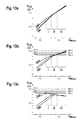
- FIG. 10b and c that the voltage increase for the voltage U LSI at the output of the converter 3 is significantly attenuated by the action of the active modules compared to the initial situation as in FIG. 10a shown.
- FIG. 10b the characteristic curve is shown for the case that a small line choke 4 is provided.
- a small line choke is understood as meaning a low inductance.
- the increase in voltage continues here into the higher ranges, but with a much weaker scope.
- the respectively achieved limit values for the voltage U LSI at the converter 3 for the different cases are plotted on the right side with 840 V as maximum.
- the design-relevant point is therefore the upper end point of the overvoltage range III (marked by a circle).
- FIG. 10c The case with a design for a large mains choke 4 is shown in FIG. 10c.
- the power transformer 8 is preferably designed so that above a predefined voltage-frequency combination, a magnetic saturation occurs. As a result, several advantages are achieved. On the one hand, the transformer 8 can be made smaller. At a designated operating frequency range 45 Hz to 55 Hz, the transformer is suitably designed so that at the lower end of the operating range (here 45 Hz) saturation occurs from an overvoltage of 116%. Due to this saturation, the transformer generates additional reactive current, which is also favorable for the protection of the plant. Preferably, the insertion point is chosen so that the effect occurs primarily in the overvoltage regions II and III.
- a frequency adaptation element 77 for the overvoltage classifier 70 is expediently provided.
Landscapes
- Engineering & Computer Science (AREA)
- Power Engineering (AREA)
- Life Sciences & Earth Sciences (AREA)
- Sustainable Development (AREA)
- Sustainable Energy (AREA)
- Chemical & Material Sciences (AREA)
- Combustion & Propulsion (AREA)
- Mechanical Engineering (AREA)
- General Engineering & Computer Science (AREA)
- Control Of Eletrric Generators (AREA)
- Protection Of Generators And Motors (AREA)
- Inverter Devices (AREA)
Applications Claiming Priority (1)
| Application Number | Priority Date | Filing Date | Title |
|---|---|---|---|
| DE102014209332.5A DE102014209332A1 (de) | 2014-05-16 | 2014-05-16 | Windenergieanlage mit verbessertem Überspannungsschutz |
Publications (3)
| Publication Number | Publication Date |
|---|---|
| EP2945242A2 true EP2945242A2 (fr) | 2015-11-18 |
| EP2945242A3 EP2945242A3 (fr) | 2016-04-06 |
| EP2945242B1 EP2945242B1 (fr) | 2020-07-01 |
Family
ID=53189661
Family Applications (1)
| Application Number | Title | Priority Date | Filing Date |
|---|---|---|---|
| EP15167549.3A Not-in-force EP2945242B1 (fr) | 2014-05-16 | 2015-05-13 | Éolienne dotée d'une protection améliorée contre les surtensions |
Country Status (4)
| Country | Link |
|---|---|
| US (1) | US9515594B2 (fr) |
| EP (1) | EP2945242B1 (fr) |
| CA (1) | CA2890982C (fr) |
| DE (1) | DE102014209332A1 (fr) |
Cited By (2)
| Publication number | Priority date | Publication date | Assignee | Title |
|---|---|---|---|---|
| EP3219986A1 (fr) * | 2016-03-18 | 2017-09-20 | Senvion GmbH | Éolienne comprenant un module de contrôle de puissance |
| WO2020125882A1 (fr) * | 2018-12-20 | 2020-06-25 | Vestas Wind Systems A/S | Renforcement d'injection de courant réactif à partir de générateurs d'éolienne |
Families Citing this family (17)
| Publication number | Priority date | Publication date | Assignee | Title |
|---|---|---|---|---|
| DE102011007696A1 (de) * | 2011-04-19 | 2012-10-25 | Siemens Aktiengesellschaft | Matrix-Umrichter und Verfahren zum Erzeugen einer Wechselspannung in einem zweiten Wechselspannungsnetz aus einer Wechselspannung in einem ersten Wechselspannungsnetz mittels eines Matrix-Umrichters |
| DE102012006259A1 (de) * | 2012-03-29 | 2013-10-02 | Repower Systems Se | Chopperverstärkter Umrichter für Windenergieanlagen |
| CN104471242B (zh) * | 2012-07-19 | 2017-12-19 | 维斯塔斯风力系统集团公司 | 操作风力涡轮机的方法及其适用系统 |
| WO2015086021A1 (fr) * | 2013-12-11 | 2015-06-18 | Vestas Wind Systems A/S | Centrale éolienne et procédé d'augmentation de la capacité de puissance réactive d'une centrale éolienne |
| WO2016155739A1 (fr) * | 2015-04-01 | 2016-10-06 | Vestas Wind Systems A/S | Procédé de gestion d'un événement de temps de maintien de surtension |
| EP3086432B1 (fr) * | 2015-04-23 | 2018-07-18 | GE Energy Power Conversion Technology Ltd | Systèmes de distribution de puissance |
| DE102015009741A1 (de) * | 2015-07-31 | 2017-02-02 | Senvion Gmbh | Windenergieanlage mit spannungsgeregelter Eigenbedarfsversorgung |
| DE102015009742A1 (de) * | 2015-07-31 | 2017-02-02 | Senvion Gmbh | Eigenbedarfssteuerung für eine Windenergieanlage |
| US10539118B2 (en) * | 2016-07-06 | 2020-01-21 | Vestas Wind Systmens A/S | Wind power plant having a plurality of wind turbine generators and a power plant controller |
| CN110234870A (zh) * | 2017-02-07 | 2019-09-13 | 西门子歌美飒可再生能源公司 | 具有辅助电源的风力涡轮机 |
| DK3376026T3 (da) * | 2017-03-13 | 2022-02-28 | Nordex Energy Se & Co Kg | Fremgangsmåde til regulering af aktiv-effekt fra en vindmøllepark, og tilsvarende vindmøllepark |
| US20190140569A1 (en) * | 2017-11-09 | 2019-05-09 | General Electric Company | DFIG Converter Overmodulation |
| US11611290B2 (en) * | 2017-12-22 | 2023-03-21 | Vestas Wind Systems A/S | Wind turbine with reduced DC-voltage reserve |
| DE102018000157A1 (de) * | 2018-01-11 | 2019-07-11 | Senvion Gmbh | Steuerung einer Windenergieanlage durch Änderung von Drehzahlparametern |
| WO2020057704A1 (fr) * | 2018-09-19 | 2020-03-26 | Vestas Wind Systems A/S | Commande d'un système de génération d'énergie d'éolienne pour optimiser une tension de liaison cc |
| WO2021083469A1 (fr) * | 2019-10-31 | 2021-05-06 | Vestas Wind Systems A/S | Éolienne dotée d'un dispositif de protection contre les surtensions |
| US12266940B2 (en) | 2020-01-21 | 2025-04-01 | Vestas Wind Systems A/S | Wind turbine power generation comprising an ac-dc-ac converter and a transformer with a tap changer |
Family Cites Families (37)
| Publication number | Priority date | Publication date | Assignee | Title |
|---|---|---|---|---|
| US3836994A (en) * | 1969-05-01 | 1974-09-17 | Gen Electric | Thyristor overvoltage protective element |
| US3662250A (en) * | 1970-11-12 | 1972-05-09 | Gen Electric | Thyristor overvoltage protective circuit |
| US5023527A (en) * | 1974-06-24 | 1991-06-11 | General Electric Company | Control circuits, electronically commutated motor systems and methods |
| US4497031A (en) * | 1982-07-26 | 1985-01-29 | Johnson Service Company | Direct digital control apparatus for automated monitoring and control of building systems |
| US5982645A (en) * | 1992-08-25 | 1999-11-09 | Square D Company | Power conversion and distribution system |
| WO1995001670A1 (fr) * | 1993-06-29 | 1995-01-12 | Square D Company | Systeme de conversion de puissance ac-cc |
| US5747972A (en) * | 1995-01-11 | 1998-05-05 | Microplanet Ltd. | Method and apparatus for electronic power control |
| DE10005449B4 (de) * | 2000-02-08 | 2008-06-12 | Siemens Ag | Überspannungsschutzvorrichtung für einen Matrixumrichter |
| DE10011518A1 (de) * | 2000-03-09 | 2001-09-27 | Siemens Ag | Rückspeisefähiger Umrichtermotor |
| DE60139067D1 (de) * | 2000-03-18 | 2009-08-06 | Areva T & D Sa | Verbesserte elektrische unterstation |
| DE10136974A1 (de) | 2001-04-24 | 2002-11-21 | Aloys Wobben | Verfahren zum Betreiben einer Windenergieanlage |
| US7990740B1 (en) * | 2004-03-19 | 2011-08-02 | Marvell International Ltd. | Method and apparatus for controlling power factor correction |
| US7733678B1 (en) * | 2004-03-19 | 2010-06-08 | Marvell International Ltd. | Power factor correction boost converter with continuous, discontinuous, or critical mode selection |
| JP4498827B2 (ja) * | 2004-06-03 | 2010-07-07 | トヨタ自動車株式会社 | 電力変換装置およびそれを備えた車両 |
| CN101091305A (zh) * | 2004-12-28 | 2007-12-19 | 维斯塔斯风力系统有限公司 | 控制连接到公用电网的风力涡轮机的方法 |
| EP1920515A4 (fr) * | 2005-08-30 | 2016-09-28 | Abb Research Ltd | Regulation de debit de puissance d'eolienne a charge de lissage et convertisseur d'energie |
| US7394166B2 (en) * | 2006-10-04 | 2008-07-01 | General Electric Company | Method, apparatus and computer program product for wind turbine start-up and operation without grid power |
| DE102006053367A1 (de) * | 2006-11-10 | 2008-05-21 | Repower Systems Ag | Verfahren und Vorrichtung zum Betrieb eines Umrichters, insbesondere für Windenergieanlagen |
| JP4957304B2 (ja) * | 2007-03-14 | 2012-06-20 | 株式会社明電舎 | 交流−交流直接変換装置の空間ベクトル変調方法 |
| DE102007017870B4 (de) | 2007-04-13 | 2022-03-31 | Senvion Gmbh | Verfahren zum Betreiben einer Windenergieanlage bei Überspannungen im Netz |
| DE102007057925A1 (de) | 2007-12-01 | 2009-06-04 | Nordex Energy Gmbh | Verfahren zum Betreiben einer Windenergieanlage mit einer spannungsabhängigen Steuerung einer bereitzustellenden elektrischen Blindgröße |
| JP5304192B2 (ja) * | 2008-03-28 | 2013-10-02 | ダイキン工業株式会社 | 電力変換装置 |
| DE102008049630A1 (de) * | 2008-09-30 | 2010-04-08 | Repower Systems Ag | Überspannungsschutzgerät für Windenergieanlagen |
| US9496717B2 (en) * | 2008-10-28 | 2016-11-15 | Technical University Of Denmark | System and method for connecting a converter to a utility grid |
| JP5013283B2 (ja) * | 2010-02-17 | 2012-08-29 | 株式会社安川電機 | マトリクスコンバータの制御装置 |
| US8405939B2 (en) * | 2010-03-08 | 2013-03-26 | Pass & Seymour, Inc. | Protective device for an electrical supply facility |
| ES2574707T3 (es) * | 2010-12-10 | 2016-06-21 | Vestas Wind Systems A/S | Un procedimiento para hacer funcionar una turbina eólica, así como un sistema adecuado para el mismo |
| WO2012083963A1 (fr) * | 2010-12-23 | 2012-06-28 | Vestas Wind Systems A/S | Procédé d'exploitation d'une éolienne et système approprié |
| US9222465B2 (en) * | 2011-04-15 | 2015-12-29 | Northeastern University | Non-rotating wind energy generator |
| EP2807743B1 (fr) * | 2012-01-24 | 2016-01-13 | Senvion GmbH | Prédicteur d'oscillations harmoniques pour parc d'éoliennes et procédé correspondant |
| EP2621070A1 (fr) * | 2012-01-26 | 2013-07-31 | Siemens Aktiengesellschaft | Procédé et agencement de fonctionnement d'un convertisseur d'éolienne |
| CN103718447B (zh) * | 2012-04-10 | 2017-06-23 | 富士电机株式会社 | 功率转换设备 |
| US9252900B2 (en) * | 2012-06-01 | 2016-02-02 | Blackberry Limited | Universal synchronization engine based on probabilistic methods for guarantee of lock in multiformat audio systems |
| DE102012218889A1 (de) | 2012-10-17 | 2014-04-17 | Robert Bosch Gmbh | Verfahren und Vorrichtung zum Übertragen von elektrischer Leistung |
| US8848410B2 (en) * | 2012-12-06 | 2014-09-30 | Kabushiki Kaisha Yaskawa Denki | Matrix converter |
| US9828971B2 (en) * | 2014-11-20 | 2017-11-28 | General Electric Company | System and method for optimizing wind turbine operation |
| US9744352B2 (en) * | 2014-11-25 | 2017-08-29 | Medtronic Bakken Research Center B.V. | Electronic module with electromagnetic interference protection |
-
2014
- 2014-05-16 DE DE102014209332.5A patent/DE102014209332A1/de not_active Ceased
-
2015
- 2015-05-11 CA CA2890982A patent/CA2890982C/fr active Active
- 2015-05-13 EP EP15167549.3A patent/EP2945242B1/fr not_active Not-in-force
- 2015-05-15 US US14/713,911 patent/US9515594B2/en not_active Expired - Fee Related
Non-Patent Citations (1)
| Title |
|---|
| None |
Cited By (3)
| Publication number | Priority date | Publication date | Assignee | Title |
|---|---|---|---|---|
| EP3219986A1 (fr) * | 2016-03-18 | 2017-09-20 | Senvion GmbH | Éolienne comprenant un module de contrôle de puissance |
| WO2020125882A1 (fr) * | 2018-12-20 | 2020-06-25 | Vestas Wind Systems A/S | Renforcement d'injection de courant réactif à partir de générateurs d'éolienne |
| US12126178B2 (en) | 2018-12-20 | 2024-10-22 | Vestas Wind Systems A/S | Boosting reactive current injection from wind turbine generators |
Also Published As
| Publication number | Publication date |
|---|---|
| US9515594B2 (en) | 2016-12-06 |
| US20150333677A1 (en) | 2015-11-19 |
| CA2890982A1 (fr) | 2015-11-16 |
| CA2890982C (fr) | 2018-02-06 |
| EP2945242B1 (fr) | 2020-07-01 |
| DE102014209332A1 (de) | 2015-11-19 |
| EP2945242A3 (fr) | 2016-04-06 |
Similar Documents
| Publication | Publication Date | Title |
|---|---|---|
| EP2945242B1 (fr) | Éolienne dotée d'une protection améliorée contre les surtensions | |
| EP1921738B1 (fr) | Méthode et dispositif de commande pour un onduleur, en particulier pour une éolienne | |
| EP1914857B1 (fr) | Dispositif de circuit électrique et procédé, en particulier pour des générateurs photovoltaic | |
| EP2275674B2 (fr) | Procédé destiné au fonctionnement d'un parc éolien | |
| EP2209205B1 (fr) | Procédé pour faire fonctionner une centrale éolienne en cas de surtensions dans le réseau | |
| DE102008049630A1 (de) | Überspannungsschutzgerät für Windenergieanlagen | |
| DE102008048258B4 (de) | Windpark und Verfahren zum Betreiben eines Windparks | |
| DE102008018748A1 (de) | Windenergieanlage mit Anschlussschutzeinrichtung | |
| EP2325984A1 (fr) | Démarrage d'un champ photovoltaïque avec haute tension à circuit ouvert | |
| EP3602768B1 (fr) | Parc éolien comprenant plusieurs aérogénérateurs | |
| DE102016009413A1 (de) | Verfahren zum Regeln der Blindleistungsabgabe eines Windparks sowie ein entsprechender Windpark | |
| DE102011077160A1 (de) | Solarmodul und Verfahren zu dessen Betrieb | |
| DE102010025647B4 (de) | Vorrichtung und Verfahren zur intelligenten Netzleistungsregulierung durch kapazitive Energiespeicherung | |
| EP2599213B1 (fr) | Système convertisseur et procédé de fonctionnement d'un système convertisseur de ce type | |
| DE102013215398A1 (de) | Verfahren zum Steuern von Windenergieanlagen | |
| EP3911856A1 (fr) | Éolienne servant à injecter de l'énergie électrique dans un réseau de distribution électrique | |
| AT515985B1 (de) | Energieversorgungsvorrichtung | |
| EP3806261B1 (fr) | Procédé d'alimentation caractérisée par tension d'énergie électrique dans un réseau d'alimentation électrique au moyen d'une éolienne | |
| EP3125401B1 (fr) | Éolienne comprenant une alimentation d'autoconsommation a tension regulee | |
| WO2022048763A1 (fr) | Système comprenant une liaison de transmission de courant continu ou une grille de transmission de courant continu et son procédé de fonctionnement | |
| EP4022733A1 (fr) | Installation et procédé pour stabiliser un réseau électrique | |
| DE102018110245A1 (de) | Verfahren und Schaltungsanordnung zur Steuerung eines Asynchrongenerators | |
| DE102010009484B4 (de) | Wechselrichter für Photovoltaikanlagen | |
| EP4002677A1 (fr) | Système de porte pour un véhicule doté d'une battant de porte et procédé de freinage sélectif d'un battant de porte à moteur électrique | |
| DE1923978A1 (de) | Verfahren zum Schutze lastgefuehrter statischer Umrichter gegen UEberspannungen |
Legal Events
| Date | Code | Title | Description |
|---|---|---|---|
| PUAI | Public reference made under article 153(3) epc to a published international application that has entered the european phase |
Free format text: ORIGINAL CODE: 0009012 |
|
| AK | Designated contracting states |
Kind code of ref document: A2 Designated state(s): AL AT BE BG CH CY CZ DE DK EE ES FI FR GB GR HR HU IE IS IT LI LT LU LV MC MK MT NL NO PL PT RO RS SE SI SK SM TR |
|
| AX | Request for extension of the european patent |
Extension state: BA ME |
|
| PUAL | Search report despatched |
Free format text: ORIGINAL CODE: 0009013 |
|
| AK | Designated contracting states |
Kind code of ref document: A3 Designated state(s): AL AT BE BG CH CY CZ DE DK EE ES FI FR GB GR HR HU IE IS IT LI LT LU LV MC MK MT NL NO PL PT RO RS SE SI SK SM TR |
|
| AX | Request for extension of the european patent |
Extension state: BA ME |
|
| RIC1 | Information provided on ipc code assigned before grant |
Ipc: H02P 9/02 20060101ALI20160301BHEP Ipc: H02J 3/18 20060101ALI20160301BHEP Ipc: H02J 3/38 20060101ALI20160301BHEP Ipc: F03D 9/00 20160101ALI20160301BHEP Ipc: H02M 5/451 20060101ALI20160301BHEP Ipc: H02M 1/32 20070101ALI20160301BHEP Ipc: H02H 7/12 20060101AFI20160301BHEP |
|
| 17P | Request for examination filed |
Effective date: 20161005 |
|
| RBV | Designated contracting states (corrected) |
Designated state(s): AL AT BE BG CH CY CZ DE DK EE ES FI FR GB GR HR HU IE IS IT LI LT LU LV MC MK MT NL NO PL PT RO RS SE SI SK SM TR |
|
| STAA | Information on the status of an ep patent application or granted ep patent |
Free format text: STATUS: EXAMINATION IS IN PROGRESS |
|
| 17Q | First examination report despatched |
Effective date: 20190607 |
|
| GRAP | Despatch of communication of intention to grant a patent |
Free format text: ORIGINAL CODE: EPIDOSNIGR1 |
|
| STAA | Information on the status of an ep patent application or granted ep patent |
Free format text: STATUS: GRANT OF PATENT IS INTENDED |
|
| RIC1 | Information provided on ipc code assigned before grant |
Ipc: H02J 3/12 20060101ALI20200128BHEP Ipc: H02M 1/32 20070101ALI20200128BHEP Ipc: F03D 9/25 20160101ALI20200128BHEP Ipc: H02J 3/18 20060101ALI20200128BHEP Ipc: H02M 1/42 20070101ALI20200128BHEP Ipc: H02M 5/458 20060101ALI20200128BHEP Ipc: H02J 3/38 20060101ALI20200128BHEP Ipc: H02H 7/12 20060101AFI20200128BHEP |
|
| INTG | Intention to grant announced |
Effective date: 20200227 |
|
| GRAS | Grant fee paid |
Free format text: ORIGINAL CODE: EPIDOSNIGR3 |
|
| GRAA | (expected) grant |
Free format text: ORIGINAL CODE: 0009210 |
|
| STAA | Information on the status of an ep patent application or granted ep patent |
Free format text: STATUS: THE PATENT HAS BEEN GRANTED |
|
| AK | Designated contracting states |
Kind code of ref document: B1 Designated state(s): AL AT BE BG CH CY CZ DE DK EE ES FI FR GB GR HR HU IE IS IT LI LT LU LV MC MK MT NL NO PL PT RO RS SE SI SK SM TR |
|
| REG | Reference to a national code |
Ref country code: AT Ref legal event code: REF Ref document number: 1287050 Country of ref document: AT Kind code of ref document: T Effective date: 20200715 Ref country code: CH Ref legal event code: EP |
|
| REG | Reference to a national code |
Ref country code: IE Ref legal event code: FG4D Free format text: LANGUAGE OF EP DOCUMENT: GERMAN |
|
| REG | Reference to a national code |
Ref country code: DE Ref legal event code: R096 Ref document number: 502015012898 Country of ref document: DE |
|
| RAP2 | Party data changed (patent owner data changed or rights of a patent transferred) |
Owner name: SENVION DEUTSCHLAND GMBH |
|
| REG | Reference to a national code |
Ref country code: DE Ref legal event code: R081 Ref document number: 502015012898 Country of ref document: DE Owner name: SIEMENS GAMESA RENEWABLE ENERGY SERVICE GMBH, DE Free format text: FORMER OWNER: SENVION GMBH, 22297 HAMBURG, DE |
|
| REG | Reference to a national code |
Ref country code: DK Ref legal event code: T3 Effective date: 20200929 |
|
| REG | Reference to a national code |
Ref country code: NL Ref legal event code: FP |
|
| REG | Reference to a national code |
Ref country code: LT Ref legal event code: MG4D |
|
| PG25 | Lapsed in a contracting state [announced via postgrant information from national office to epo] |
Ref country code: BG Free format text: LAPSE BECAUSE OF FAILURE TO SUBMIT A TRANSLATION OF THE DESCRIPTION OR TO PAY THE FEE WITHIN THE PRESCRIBED TIME-LIMIT Effective date: 20201001 |
|
| PG25 | Lapsed in a contracting state [announced via postgrant information from national office to epo] |
Ref country code: NO Free format text: LAPSE BECAUSE OF FAILURE TO SUBMIT A TRANSLATION OF THE DESCRIPTION OR TO PAY THE FEE WITHIN THE PRESCRIBED TIME-LIMIT Effective date: 20201001 Ref country code: GR Free format text: LAPSE BECAUSE OF FAILURE TO SUBMIT A TRANSLATION OF THE DESCRIPTION OR TO PAY THE FEE WITHIN THE PRESCRIBED TIME-LIMIT Effective date: 20201002 Ref country code: FI Free format text: LAPSE BECAUSE OF FAILURE TO SUBMIT A TRANSLATION OF THE DESCRIPTION OR TO PAY THE FEE WITHIN THE PRESCRIBED TIME-LIMIT Effective date: 20200701 Ref country code: LT Free format text: LAPSE BECAUSE OF FAILURE TO SUBMIT A TRANSLATION OF THE DESCRIPTION OR TO PAY THE FEE WITHIN THE PRESCRIBED TIME-LIMIT Effective date: 20200701 Ref country code: HR Free format text: LAPSE BECAUSE OF FAILURE TO SUBMIT A TRANSLATION OF THE DESCRIPTION OR TO PAY THE FEE WITHIN THE PRESCRIBED TIME-LIMIT Effective date: 20200701 Ref country code: PT Free format text: LAPSE BECAUSE OF FAILURE TO SUBMIT A TRANSLATION OF THE DESCRIPTION OR TO PAY THE FEE WITHIN THE PRESCRIBED TIME-LIMIT Effective date: 20201102 Ref country code: CZ Free format text: LAPSE BECAUSE OF FAILURE TO SUBMIT A TRANSLATION OF THE DESCRIPTION OR TO PAY THE FEE WITHIN THE PRESCRIBED TIME-LIMIT Effective date: 20200701 Ref country code: SE Free format text: LAPSE BECAUSE OF FAILURE TO SUBMIT A TRANSLATION OF THE DESCRIPTION OR TO PAY THE FEE WITHIN THE PRESCRIBED TIME-LIMIT Effective date: 20200701 Ref country code: ES Free format text: LAPSE BECAUSE OF FAILURE TO SUBMIT A TRANSLATION OF THE DESCRIPTION OR TO PAY THE FEE WITHIN THE PRESCRIBED TIME-LIMIT Effective date: 20200701 |
|
| PG25 | Lapsed in a contracting state [announced via postgrant information from national office to epo] |
Ref country code: IS Free format text: LAPSE BECAUSE OF FAILURE TO SUBMIT A TRANSLATION OF THE DESCRIPTION OR TO PAY THE FEE WITHIN THE PRESCRIBED TIME-LIMIT Effective date: 20201101 Ref country code: PL Free format text: LAPSE BECAUSE OF FAILURE TO SUBMIT A TRANSLATION OF THE DESCRIPTION OR TO PAY THE FEE WITHIN THE PRESCRIBED TIME-LIMIT Effective date: 20200701 Ref country code: LV Free format text: LAPSE BECAUSE OF FAILURE TO SUBMIT A TRANSLATION OF THE DESCRIPTION OR TO PAY THE FEE WITHIN THE PRESCRIBED TIME-LIMIT Effective date: 20200701 Ref country code: RS Free format text: LAPSE BECAUSE OF FAILURE TO SUBMIT A TRANSLATION OF THE DESCRIPTION OR TO PAY THE FEE WITHIN THE PRESCRIBED TIME-LIMIT Effective date: 20200701 |
|
| REG | Reference to a national code |
Ref country code: GB Ref legal event code: 732E Free format text: REGISTERED BETWEEN 20210304 AND 20210310 |
|
| REG | Reference to a national code |
Ref country code: DE Ref legal event code: R097 Ref document number: 502015012898 Country of ref document: DE |
|
| PG25 | Lapsed in a contracting state [announced via postgrant information from national office to epo] |
Ref country code: EE Free format text: LAPSE BECAUSE OF FAILURE TO SUBMIT A TRANSLATION OF THE DESCRIPTION OR TO PAY THE FEE WITHIN THE PRESCRIBED TIME-LIMIT Effective date: 20200701 Ref country code: RO Free format text: LAPSE BECAUSE OF FAILURE TO SUBMIT A TRANSLATION OF THE DESCRIPTION OR TO PAY THE FEE WITHIN THE PRESCRIBED TIME-LIMIT Effective date: 20200701 Ref country code: SM Free format text: LAPSE BECAUSE OF FAILURE TO SUBMIT A TRANSLATION OF THE DESCRIPTION OR TO PAY THE FEE WITHIN THE PRESCRIBED TIME-LIMIT Effective date: 20200701 Ref country code: IT Free format text: LAPSE BECAUSE OF FAILURE TO SUBMIT A TRANSLATION OF THE DESCRIPTION OR TO PAY THE FEE WITHIN THE PRESCRIBED TIME-LIMIT Effective date: 20200701 |
|
| PLBE | No opposition filed within time limit |
Free format text: ORIGINAL CODE: 0009261 |
|
| STAA | Information on the status of an ep patent application or granted ep patent |
Free format text: STATUS: NO OPPOSITION FILED WITHIN TIME LIMIT |
|
| PG25 | Lapsed in a contracting state [announced via postgrant information from national office to epo] |
Ref country code: AL Free format text: LAPSE BECAUSE OF FAILURE TO SUBMIT A TRANSLATION OF THE DESCRIPTION OR TO PAY THE FEE WITHIN THE PRESCRIBED TIME-LIMIT Effective date: 20200701 |
|
| 26N | No opposition filed |
Effective date: 20210406 |
|
| PG25 | Lapsed in a contracting state [announced via postgrant information from national office to epo] |
Ref country code: SK Free format text: LAPSE BECAUSE OF FAILURE TO SUBMIT A TRANSLATION OF THE DESCRIPTION OR TO PAY THE FEE WITHIN THE PRESCRIBED TIME-LIMIT Effective date: 20200701 |
|
| PG25 | Lapsed in a contracting state [announced via postgrant information from national office to epo] |
Ref country code: SI Free format text: LAPSE BECAUSE OF FAILURE TO SUBMIT A TRANSLATION OF THE DESCRIPTION OR TO PAY THE FEE WITHIN THE PRESCRIBED TIME-LIMIT Effective date: 20200701 |
|
| REG | Reference to a national code |
Ref country code: CH Ref legal event code: PL |
|
| PG25 | Lapsed in a contracting state [announced via postgrant information from national office to epo] |
Ref country code: CH Free format text: LAPSE BECAUSE OF NON-PAYMENT OF DUE FEES Effective date: 20210531 Ref country code: MC Free format text: LAPSE BECAUSE OF FAILURE TO SUBMIT A TRANSLATION OF THE DESCRIPTION OR TO PAY THE FEE WITHIN THE PRESCRIBED TIME-LIMIT Effective date: 20200701 Ref country code: LI Free format text: LAPSE BECAUSE OF NON-PAYMENT OF DUE FEES Effective date: 20210531 Ref country code: LU Free format text: LAPSE BECAUSE OF NON-PAYMENT OF DUE FEES Effective date: 20210513 |
|
| REG | Reference to a national code |
Ref country code: BE Ref legal event code: MM Effective date: 20210531 |
|
| PG25 | Lapsed in a contracting state [announced via postgrant information from national office to epo] |
Ref country code: IE Free format text: LAPSE BECAUSE OF NON-PAYMENT OF DUE FEES Effective date: 20210513 |
|
| REG | Reference to a national code |
Ref country code: AT Ref legal event code: MM01 Ref document number: 1287050 Country of ref document: AT Kind code of ref document: T Effective date: 20210513 |
|
| PG25 | Lapsed in a contracting state [announced via postgrant information from national office to epo] |
Ref country code: BE Free format text: LAPSE BECAUSE OF NON-PAYMENT OF DUE FEES Effective date: 20210531 |
|
| PG25 | Lapsed in a contracting state [announced via postgrant information from national office to epo] |
Ref country code: AT Free format text: LAPSE BECAUSE OF NON-PAYMENT OF DUE FEES Effective date: 20210513 |
|
| PG25 | Lapsed in a contracting state [announced via postgrant information from national office to epo] |
Ref country code: HU Free format text: LAPSE BECAUSE OF FAILURE TO SUBMIT A TRANSLATION OF THE DESCRIPTION OR TO PAY THE FEE WITHIN THE PRESCRIBED TIME-LIMIT; INVALID AB INITIO Effective date: 20150513 |
|
| REG | Reference to a national code |
Ref country code: NL Ref legal event code: HC Owner name: SIEMENS GAMESA RENEWABLE ENERGY SERVICE GMBH; DE Free format text: DETAILS ASSIGNMENT: CHANGE OF OWNER(S), CHANGE OF OWNER(S) NAME; FORMER OWNER NAME: SENVION DEUTSCHLAND GMBH Effective date: 20230526 |
|
| PG25 | Lapsed in a contracting state [announced via postgrant information from national office to epo] |
Ref country code: CY Free format text: LAPSE BECAUSE OF FAILURE TO SUBMIT A TRANSLATION OF THE DESCRIPTION OR TO PAY THE FEE WITHIN THE PRESCRIBED TIME-LIMIT Effective date: 20200701 |
|
| PGFP | Annual fee paid to national office [announced via postgrant information from national office to epo] |
Ref country code: NL Payment date: 20230519 Year of fee payment: 9 Ref country code: FR Payment date: 20230515 Year of fee payment: 9 Ref country code: DK Payment date: 20230522 Year of fee payment: 9 Ref country code: DE Payment date: 20230519 Year of fee payment: 9 |
|
| PGFP | Annual fee paid to national office [announced via postgrant information from national office to epo] |
Ref country code: GB Payment date: 20230522 Year of fee payment: 9 |
|
| PG25 | Lapsed in a contracting state [announced via postgrant information from national office to epo] |
Ref country code: MK Free format text: LAPSE BECAUSE OF FAILURE TO SUBMIT A TRANSLATION OF THE DESCRIPTION OR TO PAY THE FEE WITHIN THE PRESCRIBED TIME-LIMIT Effective date: 20200701 |
|
| PG25 | Lapsed in a contracting state [announced via postgrant information from national office to epo] |
Ref country code: TR Free format text: LAPSE BECAUSE OF FAILURE TO SUBMIT A TRANSLATION OF THE DESCRIPTION OR TO PAY THE FEE WITHIN THE PRESCRIBED TIME-LIMIT Effective date: 20200701 |
|
| PG25 | Lapsed in a contracting state [announced via postgrant information from national office to epo] |
Ref country code: MT Free format text: LAPSE BECAUSE OF FAILURE TO SUBMIT A TRANSLATION OF THE DESCRIPTION OR TO PAY THE FEE WITHIN THE PRESCRIBED TIME-LIMIT Effective date: 20200701 |
|
| REG | Reference to a national code |
Ref country code: DE Ref legal event code: R119 Ref document number: 502015012898 Country of ref document: DE |
|
| REG | Reference to a national code |
Ref country code: DK Ref legal event code: EBP Effective date: 20240531 |
|
| REG | Reference to a national code |
Ref country code: NL Ref legal event code: MM Effective date: 20240601 |
|
| GBPC | Gb: european patent ceased through non-payment of renewal fee |
Effective date: 20240513 |
|
| PG25 | Lapsed in a contracting state [announced via postgrant information from national office to epo] |
Ref country code: NL Free format text: LAPSE BECAUSE OF NON-PAYMENT OF DUE FEES Effective date: 20240601 |
|
| PG25 | Lapsed in a contracting state [announced via postgrant information from national office to epo] |
Ref country code: DE Free format text: LAPSE BECAUSE OF NON-PAYMENT OF DUE FEES Effective date: 20241203 |
|
| PG25 | Lapsed in a contracting state [announced via postgrant information from national office to epo] |
Ref country code: DK Free format text: LAPSE BECAUSE OF NON-PAYMENT OF DUE FEES Effective date: 20240531 |
|
| PG25 | Lapsed in a contracting state [announced via postgrant information from national office to epo] |
Ref country code: FR Free format text: LAPSE BECAUSE OF NON-PAYMENT OF DUE FEES Effective date: 20240531 |
|
| PG25 | Lapsed in a contracting state [announced via postgrant information from national office to epo] |
Ref country code: GB Free format text: LAPSE BECAUSE OF NON-PAYMENT OF DUE FEES Effective date: 20240513 |