EP2946464B1 - Convertisseur multiniveaux à cellules hybrides en pont complet - Google Patents
Convertisseur multiniveaux à cellules hybrides en pont complet Download PDFInfo
- Publication number
- EP2946464B1 EP2946464B1 EP13701599.6A EP13701599A EP2946464B1 EP 2946464 B1 EP2946464 B1 EP 2946464B1 EP 13701599 A EP13701599 A EP 13701599A EP 2946464 B1 EP2946464 B1 EP 2946464B1
- Authority
- EP
- European Patent Office
- Prior art keywords
- cell
- bridge
- connection terminal
- phase arm
- hybrid
- Prior art date
- Legal status (The legal status is an assumption and is not a legal conclusion. Google has not performed a legal analysis and makes no representation as to the accuracy of the status listed.)
- Active
Links
- 238000004146 energy storage Methods 0.000 claims description 55
- UFFSXJKVKBQEHC-UHFFFAOYSA-N heptafluorobutyric anhydride Chemical compound FC(F)(F)C(F)(F)C(F)(F)C(=O)OC(=O)C(F)(F)C(F)(F)C(F)(F)F UFFSXJKVKBQEHC-UHFFFAOYSA-N 0.000 claims description 10
- 230000008878 coupling Effects 0.000 claims description 8
- 238000010168 coupling process Methods 0.000 claims description 8
- 238000005859 coupling reaction Methods 0.000 claims description 8
- 238000010397 one-hybrid screening Methods 0.000 claims 2
- 210000004027 cell Anatomy 0.000 description 213
- 239000003990 capacitor Substances 0.000 description 25
- 210000004754 hybrid cell Anatomy 0.000 description 22
- 230000000903 blocking effect Effects 0.000 description 9
- 239000004065 semiconductor Substances 0.000 description 9
- 230000005540 biological transmission Effects 0.000 description 7
- 230000008901 benefit Effects 0.000 description 4
- 239000000203 mixture Substances 0.000 description 4
- 230000000670 limiting effect Effects 0.000 description 3
- 230000002829 reductive effect Effects 0.000 description 3
- 230000002441 reversible effect Effects 0.000 description 2
- 230000003068 static effect Effects 0.000 description 2
- 101150111311 C5ar2 gene Proteins 0.000 description 1
- 101000946191 Galerina sp Laccase-1 Proteins 0.000 description 1
- 101100218337 Gibberella zeae (strain ATCC MYA-4620 / CBS 123657 / FGSC 9075 / NRRL 31084 / PH-1) aurL2 gene Proteins 0.000 description 1
- 101150017281 LAC2 gene Proteins 0.000 description 1
- 101150081322 LAC3 gene Proteins 0.000 description 1
- 101100020526 Pycnoporus cinnabarinus LCC3-1 gene Proteins 0.000 description 1
- 230000002349 favourable effect Effects 0.000 description 1
- 230000006872 improvement Effects 0.000 description 1
- 230000009467 reduction Effects 0.000 description 1
- 230000000717 retained effect Effects 0.000 description 1
Images


Classifications
-
- H—ELECTRICITY
- H02—GENERATION; CONVERSION OR DISTRIBUTION OF ELECTRIC POWER
- H02M—APPARATUS FOR CONVERSION BETWEEN AC AND AC, BETWEEN AC AND DC, OR BETWEEN DC AND DC, AND FOR USE WITH MAINS OR SIMILAR POWER SUPPLY SYSTEMS; CONVERSION OF DC OR AC INPUT POWER INTO SURGE OUTPUT POWER; CONTROL OR REGULATION THEREOF
- H02M1/00—Details of apparatus for conversion
- H02M1/32—Means for protecting converters other than automatic disconnection
-
- H—ELECTRICITY
- H02—GENERATION; CONVERSION OR DISTRIBUTION OF ELECTRIC POWER
- H02M—APPARATUS FOR CONVERSION BETWEEN AC AND AC, BETWEEN AC AND DC, OR BETWEEN DC AND DC, AND FOR USE WITH MAINS OR SIMILAR POWER SUPPLY SYSTEMS; CONVERSION OF DC OR AC INPUT POWER INTO SURGE OUTPUT POWER; CONTROL OR REGULATION THEREOF
- H02M7/00—Conversion of AC power input into DC power output; Conversion of DC power input into AC power output
- H02M7/02—Conversion of AC power input into DC power output without possibility of reversal
- H02M7/04—Conversion of AC power input into DC power output without possibility of reversal by static converters
- H02M7/06—Conversion of AC power input into DC power output without possibility of reversal by static converters using discharge tubes without control electrode or semiconductor devices without control electrode
-
- H—ELECTRICITY
- H02—GENERATION; CONVERSION OR DISTRIBUTION OF ELECTRIC POWER
- H02M—APPARATUS FOR CONVERSION BETWEEN AC AND AC, BETWEEN AC AND DC, OR BETWEEN DC AND DC, AND FOR USE WITH MAINS OR SIMILAR POWER SUPPLY SYSTEMS; CONVERSION OF DC OR AC INPUT POWER INTO SURGE OUTPUT POWER; CONTROL OR REGULATION THEREOF
- H02M7/00—Conversion of AC power input into DC power output; Conversion of DC power input into AC power output
- H02M7/02—Conversion of AC power input into DC power output without possibility of reversal
- H02M7/04—Conversion of AC power input into DC power output without possibility of reversal by static converters
- H02M7/12—Conversion of AC power input into DC power output without possibility of reversal by static converters using discharge tubes with control electrode or semiconductor devices with control electrode
- H02M7/21—Conversion of AC power input into DC power output without possibility of reversal by static converters using discharge tubes with control electrode or semiconductor devices with control electrode using devices of a triode or transistor type requiring continuous application of a control signal
- H02M7/217—Conversion of AC power input into DC power output without possibility of reversal by static converters using discharge tubes with control electrode or semiconductor devices with control electrode using devices of a triode or transistor type requiring continuous application of a control signal using semiconductor devices only
- H02M7/219—Conversion of AC power input into DC power output without possibility of reversal by static converters using discharge tubes with control electrode or semiconductor devices with control electrode using devices of a triode or transistor type requiring continuous application of a control signal using semiconductor devices only in a bridge configuration
-
- H—ELECTRICITY
- H02—GENERATION; CONVERSION OR DISTRIBUTION OF ELECTRIC POWER
- H02M—APPARATUS FOR CONVERSION BETWEEN AC AND AC, BETWEEN AC AND DC, OR BETWEEN DC AND DC, AND FOR USE WITH MAINS OR SIMILAR POWER SUPPLY SYSTEMS; CONVERSION OF DC OR AC INPUT POWER INTO SURGE OUTPUT POWER; CONTROL OR REGULATION THEREOF
- H02M7/00—Conversion of AC power input into DC power output; Conversion of DC power input into AC power output
- H02M7/42—Conversion of DC power input into AC power output without possibility of reversal
- H02M7/44—Conversion of DC power input into AC power output without possibility of reversal by static converters
- H02M7/48—Conversion of DC power input into AC power output without possibility of reversal by static converters using discharge tubes with control electrode or semiconductor devices with control electrode
- H02M7/483—Converters with outputs that each can have more than two voltages levels
-
- H—ELECTRICITY
- H02—GENERATION; CONVERSION OR DISTRIBUTION OF ELECTRIC POWER
- H02M—APPARATUS FOR CONVERSION BETWEEN AC AND AC, BETWEEN AC AND DC, OR BETWEEN DC AND DC, AND FOR USE WITH MAINS OR SIMILAR POWER SUPPLY SYSTEMS; CONVERSION OF DC OR AC INPUT POWER INTO SURGE OUTPUT POWER; CONTROL OR REGULATION THEREOF
- H02M7/00—Conversion of AC power input into DC power output; Conversion of DC power input into AC power output
- H02M7/42—Conversion of DC power input into AC power output without possibility of reversal
- H02M7/44—Conversion of DC power input into AC power output without possibility of reversal by static converters
- H02M7/48—Conversion of DC power input into AC power output without possibility of reversal by static converters using discharge tubes with control electrode or semiconductor devices with control electrode
- H02M7/483—Converters with outputs that each can have more than two voltages levels
- H02M7/4835—Converters with outputs that each can have more than two voltages levels comprising two or more cells, each including a switchable capacitor, the capacitors having a nominal charge voltage which corresponds to a given fraction of the input voltage, and the capacitors being selectively connected in series to determine the instantaneous output voltage
-
- H—ELECTRICITY
- H02—GENERATION; CONVERSION OR DISTRIBUTION OF ELECTRIC POWER
- H02M—APPARATUS FOR CONVERSION BETWEEN AC AND AC, BETWEEN AC AND DC, OR BETWEEN DC AND DC, AND FOR USE WITH MAINS OR SIMILAR POWER SUPPLY SYSTEMS; CONVERSION OF DC OR AC INPUT POWER INTO SURGE OUTPUT POWER; CONTROL OR REGULATION THEREOF
- H02M7/00—Conversion of AC power input into DC power output; Conversion of DC power input into AC power output
- H02M7/66—Conversion of AC power input into DC power output; Conversion of DC power input into AC power output with possibility of reversal
- H02M7/68—Conversion of AC power input into DC power output; Conversion of DC power input into AC power output with possibility of reversal by static converters
- H02M7/72—Conversion of AC power input into DC power output; Conversion of DC power input into AC power output with possibility of reversal by static converters using discharge tubes with control electrode or semiconductor devices with control electrode
- H02M7/79—Conversion of AC power input into DC power output; Conversion of DC power input into AC power output with possibility of reversal by static converters using discharge tubes with control electrode or semiconductor devices with control electrode using devices of a triode or transistor type requiring continuous application of a control signal
- H02M7/797—Conversion of AC power input into DC power output; Conversion of DC power input into AC power output with possibility of reversal by static converters using discharge tubes with control electrode or semiconductor devices with control electrode using devices of a triode or transistor type requiring continuous application of a control signal using semiconductor devices only
-
- H—ELECTRICITY
- H02—GENERATION; CONVERSION OR DISTRIBUTION OF ELECTRIC POWER
- H02M—APPARATUS FOR CONVERSION BETWEEN AC AND AC, BETWEEN AC AND DC, OR BETWEEN DC AND DC, AND FOR USE WITH MAINS OR SIMILAR POWER SUPPLY SYSTEMS; CONVERSION OF DC OR AC INPUT POWER INTO SURGE OUTPUT POWER; CONTROL OR REGULATION THEREOF
- H02M1/00—Details of apparatus for conversion
- H02M1/0083—Converters characterised by their input or output configuration
- H02M1/0085—Partially controlled bridges
-
- H—ELECTRICITY
- H02—GENERATION; CONVERSION OR DISTRIBUTION OF ELECTRIC POWER
- H02M—APPARATUS FOR CONVERSION BETWEEN AC AND AC, BETWEEN AC AND DC, OR BETWEEN DC AND DC, AND FOR USE WITH MAINS OR SIMILAR POWER SUPPLY SYSTEMS; CONVERSION OF DC OR AC INPUT POWER INTO SURGE OUTPUT POWER; CONTROL OR REGULATION THEREOF
- H02M1/00—Details of apparatus for conversion
- H02M1/0095—Hybrid converter topologies, e.g. NPC mixed with flying capacitor, thyristor converter mixed with MMC or charge pump mixed with buck
-
- H—ELECTRICITY
- H02—GENERATION; CONVERSION OR DISTRIBUTION OF ELECTRIC POWER
- H02M—APPARATUS FOR CONVERSION BETWEEN AC AND AC, BETWEEN AC AND DC, OR BETWEEN DC AND DC, AND FOR USE WITH MAINS OR SIMILAR POWER SUPPLY SYSTEMS; CONVERSION OF DC OR AC INPUT POWER INTO SURGE OUTPUT POWER; CONTROL OR REGULATION THEREOF
- H02M7/00—Conversion of AC power input into DC power output; Conversion of DC power input into AC power output
- H02M7/42—Conversion of DC power input into AC power output without possibility of reversal
- H02M7/44—Conversion of DC power input into AC power output without possibility of reversal by static converters
- H02M7/48—Conversion of DC power input into AC power output without possibility of reversal by static converters using discharge tubes with control electrode or semiconductor devices with control electrode
- H02M7/53—Conversion of DC power input into AC power output without possibility of reversal by static converters using discharge tubes with control electrode or semiconductor devices with control electrode using devices of a triode or transistor type requiring continuous application of a control signal
- H02M7/537—Conversion of DC power input into AC power output without possibility of reversal by static converters using discharge tubes with control electrode or semiconductor devices with control electrode using devices of a triode or transistor type requiring continuous application of a control signal using semiconductor devices only, e.g. single switched pulse inverters
- H02M7/5387—Conversion of DC power input into AC power output without possibility of reversal by static converters using discharge tubes with control electrode or semiconductor devices with control electrode using devices of a triode or transistor type requiring continuous application of a control signal using semiconductor devices only, e.g. single switched pulse inverters in a bridge configuration
- H02M7/5388—Conversion of DC power input into AC power output without possibility of reversal by static converters using discharge tubes with control electrode or semiconductor devices with control electrode using devices of a triode or transistor type requiring continuous application of a control signal using semiconductor devices only, e.g. single switched pulse inverters in a bridge configuration with asymmetrical configuration of switches
Definitions
- the present invention generally relates to multilevel converters. More particularly the present invention relates to a multilevel converter configured to convert between alternating current and direct current.
- Multilevel converters are of interest to use in a number of different power transmission environments. They may for instance be used as voltage source converters in direct current power transmission systems such as high voltage direct current (HVDC) and alternating current power transmission systems, such as flexible alternating current transmission system (FACTS). They may also be used as reactive compensation circuits such as Static VAR compensators.
- HVDC high voltage direct current
- FACTS flexible alternating current transmission system
- multilevel converters In order to reduce harmonic distortion in the output of power electronic converters, where the output voltages can assume several discrete levels, so called multilevel converters have been proposed.
- converters where a number of cascaded converter cells, each comprising a number of switching units and an energy storage unit in the form of a DC capacitor have been proposed.
- Converter elements in such a converter may for instance be of the half-bridge, full-bridge or clamped double cell type.
- a half-bridge connection in upper and lower arms provides unipolar cell voltage contributions and offers the simplest structure of the chain link converter. This type is described by Marquardt, 'New Concept for high voltage-Modular multilevel converter', IEEE 2004 and A. Lesnicar, R. Marquardt, "A new modular voltage source inverter topology", EPE 2003 .
- full-bridge cells This is described in WO 2011/012174 .
- Series connection of full-bridge cells offers four quadrant power flows through the energy storage element of the cell capacitor as well as DC fault voltage blocking capability by imposing a reverse voltage.
- full-bridge cells doubles the number of components compared with a half-bridge cell.
- One way to reduce the number of components combined with a retained fault current limiting ability is through mixing the cells of the half- and full-bridge type.
- Half of the cells may then be full-bridge cells used for imposing the reverse voltage due to the rating of the cascaded converter cells. This is for instance described in WO 2011/042050 .
- the mixing of cells reduces the number of components further while retaining a good fault current limitation ability.
- US 2012/243282 discloses a submodule of a high-voltage inverter that has a first sub-unit with a first energy storage device, a first series circuit of two power semiconductor switching units connected in parallel with the first energy storage device, each including a switchable power semiconductor, having the same pass-through direction, and each being conductive opposite the nominal pass-through direction.
- a first connection terminal is connected to the potential point between the power semiconductor switching units of the first series circuit.
- a second sub-unit has a second energy storage device, a second series circuit of two power semiconductor switching units connected in parallel with the second energy storage device, each including a switchable power semiconductor, having the same pass-through direction, and each being conductive opposite the nominal pass-through direction.
- a second connection terminal is connected to the potential point between the power semiconductor switching units of the second series circuit.
- the first and second sub-units are connected to each other by connections designed such that a current flow between the first connection terminal and the second connection terminal in both directions takes place only via the first energy storage device and/or the second energy storage device in a selected switching state of all power semiconductor switching units.
- the present invention is directed towards reducing the number of components in a voltage source converter combined with providing sufficient fault current limitation.
- This object is according to a first aspect achieved through a multilevel converter as disclosed in claim 1.
- the present invention has a number of advantages. It provides equal fault limiting capability as similar conventional converter structures with a reduced number of components. This is combined with a modular cell structure with low complexity and low costs. Another advantage is that the number of control signals needed for controlling the cell are reduced.
- Fig. 1 shows one variation of a multilevel converter in the form of a cell based voltage source converter 10.
- the converter operates to convert between alternating current (AC) and direct current (DC).
- the converter 10 in fig. 1 comprises a three-phase bridge made up of a number of phase legs. There are in this case three phase legs. It should however be realized that as an alternative there may be for instance only two phase legs. There is thus a first phase leg PL1, a second phase leg PL2 and a third phase leg PL3.
- the phase legs are more particularly connected between two DC poles, a first DC pole P1 and a second DC pole P2 and the mid points of the phase legs are connected to corresponding alternating current terminals AC1, AC2, AC3.
- phase leg The midpoint of a phase leg is here connected to a corresponding AC terminal via a reactor LAC1, LAC2 and LAC3.
- a phase leg is thereby divided into two halves, an upper half and a lower half, where such a half is also termed a phase arm.
- the first DC pole P1 furthermore has a first potential +DC that may be positive, while the second DC pole has a second potential -DC that may be negative.
- the first pole P1 may therefore also be termed a positive pole, while the second pole P2 may be termed negative pole.
- poles may furthermore be part of a DC power transmission system such as a High Voltage Direct Current (HVDC) power transmission system or a flexible alternating current transmission system (FACTS).
- HVDC High Voltage Direct Current
- FACTS flexible alternating current transmission system
- the voltage source converter of fig. 1 is only one example of a multilevel converter where the invention may be used. It is for instance possible to provide the three phase legs in series with each other between the two poles, where these then make up a first set of phase legs. It is then possible to provide a second set of series-connected phase legs in parallel with the first set. In this case the midpoints of the phase legs of the first set forms primary AC terminals and the midpoints of the phase legs of the second set forms secondary AC terminals for the three phases.
- Yet another realization of a multilevel converter is a static VAR compensator.
- the phase arms of the voltage source converter 10 in the example in fig. 1 comprise cells.
- a cell is a unit that may be switched for providing a voltage contribution to the voltage on the corresponding AC terminal.
- a cell then comprises one or more energy storage elements, for instance in the form of capacitors, and the cell may be switched to provide a voltage contribution corresponding to the voltage of the energy storage element or a zero voltage contribution. If more than one energy storage element is included in a cell it is possible with even further voltage contributions.
- the cells are with advantage connected in series or in cascade in a phase arm.
- the upper phase arm of the first phase leg PL1 includes five cells C1u1, C2u1, C3u1, C4u1 and C5u1, while the lower phase arm of the first phase leg PL1 includes five cells C1l1, C2l1, C3l1, C4l1 and C5l1.
- the upper phase arm of the second phase leg PL2 includes five cells C1u2, C2u2, C3u2, C4u2 and C5u2 while the lower phase arm of the second phase leg PL2 includes five cells C1l2, C2l2, C3l2, C4l2 and C5l2.
- the upper phase arm of the third phase leg PL3 includes five cells C1u3, C2u3, C3u3, C4u3 and C5u3 while the lower phase arm of the third phase leg PL3 includes five cells C1l3, C2l3, C3l3, C4l3 and C5l3.
- the number of cells provided in fig. 1 is only an example. It therefore has to be stressed that the number of cells in a phase arm may vary. It is often favorable to have many more cells in each phase arm, especially in HVDC applications. A phase arm may for instance comprise hundreds of cells. There may however also be fewer.
- Control of each cell in a phase arm is normally done through providing the cell with a control signal directed towards controlling the contribution of that cell to meeting a reference voltage.
- the reference voltage may be provided for obtaining a waveform on the AC terminal of a phase leg, for instance a sine wave. In order to control the cells there is therefore a control unit 12.
- the control unit 12 is provided for controlling all the phase arms of the converter. However, in order to simplify the figure only the control of the upper phase arm of the first phase leg PL is indicated in fig. 1 .
- phase arms are controlled in a similar manner in order to form output waveforms on the three AC terminals AC1, AC2 and AC3.
- a hybrid full-bridge cell is in the context discussed here defined as a full-bridge cell where one bridge unit comprising at least one switching element anti-parallel unidirectional conducting element pair is replaced by at least one unidirectional conducting element.
- a hybrid full-bridge cell in the definition used here is in one specific example thus a full-bridge where one of the switches is replaced by a diode. Thereby the cell can furthermore be termed an asymmetric full-bridge cell or an asymmetric hybrid full-bridge cell.
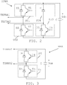
- Fig. 2 shows a first type of hybrid full-bridge cell HFBA that is to be provided in the upper phase arm of the first phase leg.
- the cell HFBA is thus a hybrid full-bridge converter cell and includes an energy storage element, here in the form of a capacitor C, which is connected in parallel with a first group of semiconducting units SU1 and SU2.
- the energy storage element provides a voltage Udm, and therefore has a positive and negative end, where the positive end has a higher potential than the negative end.
- the semiconducting units SU1 and SU2 in the first group are connected in series with each other.
- the first group here includes two semiconducting units SU1 and SU2 (shown as dashed boxes).
- each switch may be realized in the form of a switching element that may be an IGBT (Insulated Gate Bipolar Transistor) transistor together with an anti-parallel unidirectional conducting element.
- the first semiconducting unit SU1 is therefore provided as a first switch S1 having a first transistor T1 with a first anti-parallel diode D1.
- the first diode D1 is connected between the emitter and collector of the transistor T1 and has a direction of conductivity from the emitter to the collector as well as towards the positive end of the energy storage element C.
- the second semiconducting unit SU2 is provided as a second switch S2 having a second transistor T2 with a second anti-parallel diode D2.
- the second diode D2 is connected in the same way in relation to the energy storage element C as the first diode D1, i.e. conducts current towards the positive end of the energy storage element C.
- the first semiconducting unit SU1 is furthermore connected to the positive end of the energy storage element C, while the second semiconducting unit SU2 is connected to the negative end of the energy storage element C.
- the second group includes a third semiconducting unit SU3 and a fourth semiconducting unit SU4.
- the third semiconducting unit SU3 is provided as a third switch S3, here provided through a third transistor T3 with anti-parallel third diode D3.
- the fourth semiconducting unit SU4 is not a switch. It only comprises one type of semiconducting element, a unidirectional conduction element, a diode D.
- the fourth semiconducting unit SU4 thus consists of unidirectional conducting elements, where the number of such elements is at least one. This second group of semiconducting units is thus provided in a further branch in parallel with the capacitor C.
- the fourth semiconductor unit SU4 is furthermore connected to the positive end of the energy storage element C, while the third semiconducting unit SU3 is connected to the negative end of the energy storage element C. Both the diodes D3 and D furthermore have a direction of current conduction towards the positive end of the energy storage element C.
- This first type of hybrid full-bridge cell HFBA comprises a first cell connection terminal TEFBA1 and a second cell connection terminal TEFBA2, each providing a connection for the cell to the upper phase arm of the first phase leg of the voltage source converter.
- the first cell connection terminal TEFBA1 more particularly provides a connection from the upper phase arm to the junction between the first and the second semiconducting units SU1 and SU2, while the second cell connection terminal TEFBA2 provides a connection between the upper phase arm and a connection point between the third and fourth semiconducting units SU3 and SU4.
- the junction between the first and second semiconducting units SU1 and SU2 thus provides one cell connection terminal TEFBA1, while the junction between the third and fourth semiconducting units SU3 and SU4 provides a further cell connection terminal TEFBA2.
- These connection terminals TEFBA1 and TEFBA2 thus provide points where the cell HFBA can be connected to the upper phase arm of the first phase leg.
- the first cell connection terminal TEFBA1 thereby joins the upper phase arm with the connection point or junction between two of the series-connected switches of the first group, here the first and second switches
- the second cell connection terminal TEFBA2 joins the upper phase arm with a connection point between two of the series connected semiconducting units of the second group, here between the third switch and the sole diode D.
- the first cell connection terminal TEFBA1 furthermore faces the first pole and thereby couples the cell to the first pole, while the second cell connection terminal TEFBA2 faces the AC terminal of the phase leg and thereby couples the cell to the AC terminal.
- the further diode D also couples the second cell connection terminal TEFBA2 to the positive end of the energy storage element.
- the expression couple or coupling is intended to indicate that more components, such as more cells and inductors, may be connected between the pole and the cell, while the expression connect or connecting is intended to indicate a direct connection between two components such as two cells. There is thus no component in-between two components that are connected to each other.
- Fig. 3 schematically shows a first type of half-bridge converter cell HBA that may be used in the upper phase arm of the first phase leg.
- this cell includes an energy storage element, here in the form of a capacitor C, which is connected in parallel with a group of switches.
- this energy storage element C provides a voltage Udm, and thus also has a positive and negative end, where the positive end has a higher potential than the negative end.
- the switches in this group are connected in series with each other.
- the group here includes a fourth and a fifth switch S4 and S5 (shown as dashed boxes), where each switch S4, S5 may be realized in the form of a switching element that may be an IGBT (Insulated Gate Bipolar Transistor) transistor together with an anti-parallel unidirectional conduction element, which may be a diode.
- IGBT Insulated Gate Bipolar Transistor
- a fourth switch S4 having a fourth transistor T4 with a fourth anti-parallel diode D4, where the diode D4 has a direction of current conduction towards the positive end of the energy storage element C and a fifth switch S5 connected in series with the fourth switch S4 and having a fifth transistor T5 with anti-parallel diode D5, where the diode D5 has the same direction of current conduction as the fourth diode D4.
- the fourth switch S4 is connected to the positive end of the energy storage element C, while the fifth switch S5 is connected to the negative end of the energy storage element C.
- This first type of half-bridge cell HBA also comprises a first cell connection terminal TEHBA1 and a second cell connection terminal TEHBA2, each providing a connection for the cell to the upper phase arm of the first phase leg of the voltage source converter.
- the first cell connection terminal TEHBA1 more particularly provides a connection from the upper phase arm to the junction between the fourth switch S4 and the capacitor C, while the second connection terminal TEHBA2 provides a connection from the upper phase arm to the junction between the fourth and the fifth switches S4 and S5.
- the second cell connection terminal TEHBA2 thus joins the phase arm with the connection point or junction between two of the series-connected switches of the first group, here the fourth and fifth switches S4 and S5, while the first cell connection terminal TEHBA1 joins the upper phase arm with a connection point between the fourth switch S4 and the positive end of the capacitor C. Also here the first cell connection terminal TEHBA1 faces the first pole, while the second cell connection terminal TEHBA2 faces the AC terminal of the phase leg.
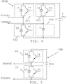
- Fig. 4 shows a second type of hybrid full-bridge cell HFBB that may be provided in the second phase arm of the first phase leg.
- the cell HFBB is thus a hybrid full-bridge converter cell and also includes an energy storage element, here in the form of a capacitor C, which is connected in parallel with a first group of semiconducting units. Also this energy storage element C provides a voltage Udm, and therefore has a positive and negative end, where the positive end has a higher potential than the negative end.
- the first group also here includes two series-connected semiconducting units SU1 and SU2 (shown as dashed boxes) in the form of switches S1 and S2. In fig. 4 there is a first switch S1 having a first transistor T1 with a first anti-parallel diode D1, where the diode D1 has a direction of current conduction towards the positive end of the energy storage element C.
- the first semiconducting unit SU1 is also here connected to the positive end of the energy storage element C, while the second semiconducting unit SU2 is connected to the negative end of the energy storage element C.
- the second group also here includes a third semiconducting unit SU3 and a fourth semiconducting unit SU4, where the third semiconducting unit SU3 is provided through a third switch S3 comprising a third transistor T3 with anti-parallel third diode D3 and the fourth semiconducting unit SU4 is provided using only unidirectional conduction elements, in this example a diode D.
- the fourth semiconducting unit SU4 thereby consists of a number of unidirectional conducting elements, comprising at least one element.
- the second group of semiconducting units is thus provided in a further branch in parallel with the capacitor C.
- the fourth semiconductor unit SU4 is in this case connected to the negative end of the energy storage element C, while the third semiconducting unit SU3 is connected to the positive end of the energy storage element C.
- the current conducting direction of both diodes D3 and D is towards the positive end of the energy storage element C.
- This second type of hybrid full-bridge cell HFBB comprises a first cell connection terminal TEFBB1 and a second cell connection terminal TEFBB2, each providing a connection for the cell to the lower phase arm of the voltage source converter, i.e. the lower phase arm of the first phase leg.
- the first cell connection terminal TEFBB1 provides a connection from the lower phase arm to the junction between the first and the second semiconducting units SU1 and SU2
- the second cell connection terminal TEFBB2 provides a connection between the lower phase arm and the connection point between the third and fourth semiconducting units SU3 and SU4.
- the junction between the first and the second switching units SU1 and SU2 thus provide a cell connection terminal and the junction between the third and fourth semiconducting units SU3 and SU4 provide a further cell connection terminal.
- the first cell connection terminal TEFBB1 furthermore faces the second pole and thereby couples the cell to the second pole, while the second cell connection terminal TEFBB2 faces the AC terminal of the phase leg.
- the second cell connection terminals thereby couples the cell to the AC terminal of the phase leg, while the at least one unidirectional conducting element couples the second cell connection terminal to the negative end of energy storage element C.
- Fig. 5 shows a corresponding second type of half-bridge cell HBB for connection in the lower phase arm of the first phase leg. It comprises a group of switches comprising a fourth and fifth switch S4 and S5 connected in the same way as the fourth and fifth switches of the first type of half-bridge cell.
- the first cell connection terminal TEHBB1 provides a connection from the lower phase arm to the junction between the fourth and the fifth switches S4 and S5, while the second cell connection terminal TEHBB2 provides a connection from the lower phase arm to the junction between the fifth switch S5 and the negative end of the capacitor C.
- the first cell connection terminal TEHBB1 faces the second pole, while the second cell connection terminal TEHBB2 faces the AC terminal of the phase leg.
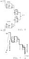
- Fig. 6 schematically shows a phase leg where the upper phase arm comprises the first type of hybrid full bridge cells and the first type of half-bridge cells, while the lower phase arm comprises the second type of hybrid full bridge cells and the second type of half-bridge cells connected in the above described way.
- the number of hybrid full-bridge cells in the upper phase arm may be between 20 and 100% of all the cells in the upper phase arm, may advantageously be between 20 and 50% and may as an example be 50%, while the rest of the cells in the upper phase arm are half-bridge cells. The same distribution may be provided in the lower phase arm.
- the first type of hybrid full-bridge cell and the first type of half-bridge cell of the upper arm of the phase leg shown in fig. 6 are operated according to the switching table below, table 1.
- table 1 the switching states of the first, second and third switches S1, S2 and S3 of the first type of hybrid full bridge cell are shown together with the switching states of the fourth and fifth switches S4 and S5 of the first type of half-bridge cell.
- the two cells are considered as a pair together providing a voltage Vout.
- the table therefore shows the combination of switching states causing a voltage contribution that lowers the first pole voltage +DC.
- the switching states of the switches of the second type of hybrid full bridge cell and the second type of half-bridge cell of the lower phase arm of the phase leg shown in fig. 6 are operated according to the switching table below, table 2.
- the switching states of the first, second and third switches S1, S2 and S3 of the second type of hybrid full-bridge cell are shown together with the switching states of the fourth and fifth switches S4 and S5 of the second type of half-bridge cell.
- the two cells are considered as a pair together providing a voltage Vout.
- the table thus shows the combination of switching states causing a voltage contribution that raises the second pole voltage -DC.
- the second branch of semiconducting units i.e. the branch comprising the third and the fourth semiconducting units, here the branch with the third switch S3 and the diode D
- the third switch S3 is redundant in normal operation. This can be seen through the third switch S3 always being turned on. This means that the third switch S3 does in normal operation always provide a current path between the AC terminal of the phase leg and the corresponding pole. It can also be seen that therefore there is no needed for any switching element in parallel with the diode D of the fourth semiconducting unit of the full-bridge cells.
- full-bridge cells are ordinarily not for improving the normal operation, but to be able to limit and sometimes also block fault currents in case of a DC pole fault, such as a pole-to-pole fault or a pole-to-ground fault.
- a DC pole fault such as a pole-to-pole fault or a pole-to-ground fault.
- the voltage at the AC terminal of as phase leg can be considered as forming an AC voltage source VAC feeding the phase leg with an AC voltage.
- the switching elements of all the switches may be opened by the control unit of the converter.
- the switching element of the third switch S3 may more particularly be open, at least in the negative half period of the AC voltage for the first type of hybrid full-bridge cell HFBA and at least in the positive half period of the AC voltage for the second type of hybrid full-bridge cell HFBB.
- Fig. 7 shows the fault current through the upper phase arm of fig. 6 in case of a positive pole-to-ground fault at a positive half period of the AC voltage cycle of the AC voltage source VAC and fig. 8 shows the fault current through the upper phase arm of fig. 6 in case of a positive pole-to-ground fault at a negative half period of the AC voltage cycle of the AC voltage source VAC.
- the fault current will, in the positive half-period of the AC voltage source VAC, run from the AC voltage source VAC, through the fourth switch S4, through the diode D, through the hybrid cell capacitor and through the diode of the second switch S2 to the first pole. It can also be seen that since the first pole has a positive potential during normal operation, the diode D is together with the second switch S2 connected in a branch between the first and the second cell connection terminals of the hybrid cell that couples the negative end of the hybrid cell energy storage unit to the first pole. It can in this way be seen that the diode D couples an end of the hybrid cell energy storage unit to a pole, which end has a polarity that is opposite to the polarity of the pole in normal operation.
- the fault current will, in the negative half-period of the AC voltage source VAC, flow from the first pole, through the first switch S1, through the hybrid cell capacitor, through the diode of the third switch S3, through the half-bridge cell capacitor and through the diode of the fifth switch S5 to the AC voltage source VAC.
- the switching element of the third switch S3 is needed in order for the current to pass through hybrid cell capacitor in the situation depicted in fig. 7 .
- the diode D functions to couple the energy storage element of the hybrid full bridge cell HFBA between the first and the second cell connection terminals of the hybrid full bridge cell HFBA with a polarity that counteracts negative currents in the phase arm. This means that when the diode D is conducting, the negative end of the hybrid full-bridge cell capacitor faces the first pole P1 and the positive end faces the AC terminal AC1.
- Fig. 9 shows the fault current through the lower phase arm of fig. 6 in case of a negative pole-to-ground fault at the negative half period of the AC voltage cycle of the AC voltage source VAC and fig. 10 shows the fault current through the lower phase arm of fig. 6 in case of a negative pole-to-ground fault at the positive half period of the AC voltage cycle of the AC voltage source VAC.
- the fault current will, in the negative half-period of the voltage source VAC, flow from the second pole, through the diode of the first switch S1, through the hybrid cell capacitor, through the diode D and through the diode of the fifth switch S5 to the AC voltage source VAC.
- the diode D is together with the first switch S1 provided in a branch between the first and the second cell connection terminals of the hybrid cell that couples the positive end of the hybrid cell energy storage unit to the second pole. It can in this way be seen that the diode D couples an end of the hybrid cell energy storage unit to a pole, which end has a polarity that is opposite to the polarity of the pole in normal operation.
- the fault current will, in the positive half-period of the AC voltage source VAC, run from the AC voltage source VAC, through the fourth switch S4, through the half-bridge cell capacitor, through the diode of the third switch S3, through the hybrid cell capacitor and through the diode of the second switch S2 to the second pole. It can also here be seen that the switching element of the third switch S3 is needed in order for the current to pass through hybrid cell capacitor in the situation depicted in fig. 9 . However, there is no need for a switching element in parallel with the diode D for obtaining the same result in the situation in fig. 10 .
- the diode D functions to couple the energy storage element of the hybrid full bridge cell HFBB between the first and the second cell connection terminals of the hybrid full bridge cell HFBB with a polarity that counteracts negative currents in the phase arm. This means that when the diode D is conducting the positive end of the hybrid full-bridge cell capacitor faces the second pole P2 and the negative end faces the AC terminal AC1.
- the fault current because of a pole-to-ground fault of the corresponding pole may be completely blocked.
- This structure operates in the same way as normal cascaded two level half-bridge cells (CTL) while one of the active switches, the third switch, of the hybrid cell is always ON and generate either 2Udm, Udm, 0 voltage levels, according to different switching states. However, in case of a DC fault, this third switch is turned OFF to provide an opposite voltage polarity according to the fault position in upper or lower arm. This results in the DC fault being blocked or limited.
- CTL normal cascaded two level half-bridge cells
- the cell structure comprises 5 transistor antiparallel diode pairs and only one extra diode which can save one active switch compared to a converter configuration where there is a mix of half-bridge cells and conventional full-bridge cells.
- hybrid cell structures used both in the upper and lower phase arms may be varied.
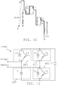
- a third type of hybrid cell structure HFBC that may be used in the upper phase arm is schematically shown in fig. 11 .
- This type differs from the structure of the first type through the fourth semiconducting unit SU4 with the diode D being connected to the negative end of the cell capacitor C and the third semiconducting unit SU3 being connected to the positive end of the cell capacitor C.
- the first cell connection terminal TEFBC1 is further provided at the junction between the third and fourth semiconducting units SU3 and SU4, while the second cell connection terminal TEFBC2 is provided between the first and second semiconducting units SU1 and SU2.
- the first cell connection terminal TEFBC1 is a further cell connection terminal coupling the cell HFBC to the first pole and the at least one unidirectional conducting element couples the first cell connection terminal TEFBC1 to the negative end of the energy storage element C.
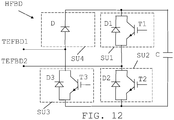
- a fourth type of hybrid cell structure HFBD that may be used in the lower phase arm is schematically shown in fig. 12 .
- the first cell connection terminal TEFBD1 is further provided at the junction between the third and fourth semiconducting units SU3 and SU4, while the second cell connection terminal TEFBD2 is provided between the first and second semiconducting units SU1 and SU2.
- the first cell connection terminal TEFBD1 which is here a further cell connection terminal, couples the cell to the second pole and the at least one unidirectional conducting element D couples the first cell connection terminal TEFBD1 to the positive end of the energy storage element C.
- the third type of hybrid cell may replace the first type in the upper arm.
- the third type may also be combined with the first type. There may thus be cells of both the first and the third type of hybrid cell in the upper phase arm.
- the fourth type of hybrid cell may replace the second type in the lower arm. It may also be combined with the second type. There may thus be cells of both the second and the fourth type of hybrid cells in the lower phase arm.
- phase arms comprises hybrid full-bride cells. This may be of interest if pole-to-ground faults of one of the poles are extremely rare. This may be the case if one of the poles is an overhead line while the other is provided through a cable. All cells of a phase arm may also be hybrid cells.
- the distribution between the hybrid full-bridge cells and the half-bridge cells may furthermore vary.
- the percentage of hybrid-full bridge cells in a phase arm may for instance vary between 20 and 100%. As an alternative it may vary between 20 and 50%. 50% is normally the percentage required for full fault current blocking ability. A higher percentage may be wanted if redundancy is an issue, while a lower may be used if only fault current limitation is desired.
- the other cells, i.e. the cells that are not hybrid full-bridge cells are furthermore not necessarily half-bridge cells. They can also be full-bridge cells or clamped double-cells. It is furthermore possible with a different distribution of hybrid full-bridge cells in the two phase arms.
- the hybrid full-bridge cells may furthermore be provided in other types of converters than the ones shown, such is in converters that employ full bridge-cells combined with director switches, which director switches operate at a fundamental frequency for selectively connecting an AC terminal to a waveform produced by cells in a phase arm.
Landscapes
- Engineering & Computer Science (AREA)
- Power Engineering (AREA)
- Inverter Devices (AREA)
- Rectifiers (AREA)
Claims (8)
- Convertisseur de source de tension multiniveau (10) configuré pour convertir un courant alternatif (CA) en courant continu (CC) ou vice versa et comprenant des jambes de phase branchées entre deux pôles CC (P1, P2), chaque jambe de phase comprenant un bras de phase supérieur et un bras de phase inférieur, les bras de phase comprenant un nombre de cellules entre un pôle CC (P1 ; P2) et une borne CA (AC1), lesdites cellules comprenant au moins une cellule hybride en pont complet (HFBA ; HFBB, HFBC ; HFBD) pour une opération de gestion de courant de défaut, chaque cellule dans le bras de phase étant commandable pour contribuer au respect d'une tension de référence destinée à obtenir une forme d'onde sur la borne CA de la jambe de phase,
ladite cellule hybride en pont complet étant composée de :une première borne de branchement de cellule pour couplage au pôle CC,une deuxième borne de branchement de cellule pour couplage à la borne CA,un élément de stockage d'énergie (C) ayant une extrémité positive et une extrémité négative,un premier groupe d'unités semi-conductrices branchées en série, lequel groupe est branché en parallèle avec l'élément de stockage d'énergie (C), et où les unités semi-conductrices (SU1, SU2) du premier groupe comprennent des premier et deuxième éléments de commutation (T1, T2) avec des premier et deuxième éléments conducteurs unidirectionnels antiparallèles (D1, D2), où une jonction entre la première et la deuxième unité semi-conductrice forme une borne de branchement de cellule (TEFBA1 ; TEFBB1 ; TEFBC2 ; TEFBD2), etun deuxième groupe d'unités semi-conductrices branchées en série, lequel groupe est branché en parallèle avec l'élément de stockage d'énergie (C) ainsi qu'avec le premier groupe, et où le deuxième groupe comprend uniquement une troisième unité semi-conductrice (SU3) ayant un troisième élément de commutation (T3) avec un élément conducteur unidirectionnel antiparallèle (D3) et une quatrième unité semi-conductrice (SU4), où une jonction entre la troisième et la quatrième unité semi-conductrice forme une autre borne de branchement de cellule (TEFBA2 ; TEFBB2 ; TEFBC1 ; TEFBD1) qui est la première ou la deuxième borne de branchement de cellule, la quatrième unité semi-conductrice est composée d'au moins un élément conducteur unidirectionnel (D), où il n'y a aucun élément de commutation en parallèle avec l'au moins un élément conducteur unidirectionnel, et le troisième élément de commutation (T3) de la troisième unité semi-conductrice (SU3) dans le deuxième groupe est toujours configuré pour être passant lors du fonctionnement normal du convertisseur,dans lequel une cellule hybride en pont complet (HFBA ; HFBC) est disposée dans un bras de phase positif entre un premier pôle (P1) et la borne CA (AC1) et une autre cellule hybride en pont complet (HFBB ; HFBD) est disposée dans un bras de phase négatif entre un deuxième pôle (P2) et la borne CA (AC1),dans lequel, dans la cellule hybride en pont complet dans le bras de phase positif, l'autre borne de branchement de cellule est la première borne de branchement de cellule (TEFBC1) couplant la cellule hybride en pont complet (HFBC) au premier pôle (P1) et l'au moins un élément conducteur unidirectionnel (D) couple l'autre borne de branchement de cellule (TEFBC1) à l'extrémité négative de l'élément de stockage d'énergie (C), et dans la cellule hybride en pont complet dans le bras de phase négatif, l'autre borne de branchement de cellule est la première borne de branchement de cellule (TEFBD1) couplant la cellule hybride en pont complet (HFBD) au deuxième pôle (P2) et l'au moins un élément conducteur unidirectionnel (D) couple l'autre borne de branchement de cellule (TEFBD1) à l'extrémité positive de l'élément de stockage d'énergie, oudans lequel, dans la cellule hybride en pont complet dans le bras de phase positif, l'autre borne de branchement de cellule est la deuxième borne de branchement de cellule (TEFBA2) couplant la cellule hybride en pont complet (HFBA) à la borne CA (AC1) et l'au moins un élément conducteur unidirectionnel (D) couple l'autre borne de branchement de cellule (TEFBA2) à l'extrémité positive de l'élément de stockage d'énergie (C), et dans la cellule hybride en pont complet dans le bras de phase négatif, l'autre borne de branchement de cellule est la deuxième borne de branchement de cellule (TEFBB2) couplant la cellule hybride en pont complet (HFBB) à la borne CA (AC1) de la jambe de phase et l'au moins un élément conducteur unidirectionnel (D) couple l'autre borne de branchement de cellule (TEFBB2) à l'extrémité négative de l'élément de stockage d'énergie (C) . - Convertisseur multiniveau selon la revendication 1, dans lequel tous les éléments de commutation de la cellule hybride en pont complet sont configurés pour être bloqués si un courant de défaut dû à un défaut de pôle CC circule à travers le bras de phase.
- Convertisseur multiniveau selon une quelconque revendication précédente, dans lequel la direction de conduction des éléments conducteurs unidirectionnels de la cellule hybride en pont complet est dirigée vers l'extrémité positive de l'élément de stockage d'énergie.
- Convertisseur multiniveau selon une quelconque revendication précédente, dans lequel la quatrième unité semi-conductrice couple l'élément de stockage d'énergie entre la première et la deuxième borne de branchement de cellule avec une polarité qui neutralise des courants négatifs dans le bras de phase.
- Convertisseur multiniveau selon une quelconque revendication précédente, dans lequel le pourcentage de cellules hybrides en pont complet dans le bras de phase se situe dans la gamme de 20-100.
- Convertisseur multiniveau selon la revendication 5, dans lequel le pourcentage de cellules hybrides en pont complet dans le bras de phase est de 50.
- Convertisseur multiniveau selon une quelconque revendication précédente, dans lequel chaque bras de phase comprend au moins une cellule de convertisseur en demi-pont (HBA ; HBB).
- Convertisseur multiniveau selon une quelconque revendication précédente, dans lequel un bras de phase comprend au moins un commutateur directeur configuré pour brancher sélectivement la borne CA (AC1) à une forme d'onde produite par des cellules dans le bras de phase.
Applications Claiming Priority (1)
| Application Number | Priority Date | Filing Date | Title |
|---|---|---|---|
| PCT/EP2013/051027 WO2014111164A1 (fr) | 2013-01-21 | 2013-01-21 | Convertisseur multiniveaux à cellules hybrides en pont complet |
Publications (2)
| Publication Number | Publication Date |
|---|---|
| EP2946464A1 EP2946464A1 (fr) | 2015-11-25 |
| EP2946464B1 true EP2946464B1 (fr) | 2019-12-18 |
Family
ID=47624043
Family Applications (1)
| Application Number | Title | Priority Date | Filing Date |
|---|---|---|---|
| EP13701599.6A Active EP2946464B1 (fr) | 2013-01-21 | 2013-01-21 | Convertisseur multiniveaux à cellules hybrides en pont complet |
Country Status (4)
| Country | Link |
|---|---|
| US (1) | US9716425B2 (fr) |
| EP (1) | EP2946464B1 (fr) |
| CN (1) | CN105191093B (fr) |
| WO (1) | WO2014111164A1 (fr) |
Cited By (1)
| Publication number | Priority date | Publication date | Assignee | Title |
|---|---|---|---|---|
| EP4436021A1 (fr) * | 2023-03-23 | 2024-09-25 | GE Energy Power Conversion Technology Ltd | Convertisseur ca-cc-ca pour applications d'entraînement de moteur |
Families Citing this family (29)
| Publication number | Priority date | Publication date | Assignee | Title |
|---|---|---|---|---|
| EP2768133B1 (fr) * | 2013-02-14 | 2015-11-04 | ABB Technology Ltd | Cellule de convertisseur à pertes de puissance réduites, convertisseur multiniveau haute tension et procédé associé |
| EP2782239A1 (fr) * | 2013-03-21 | 2014-09-24 | Alstom Technology Ltd | Convertisseur électronique de puissance |
| CN103280989B (zh) * | 2013-05-15 | 2017-02-08 | 南京南瑞继保电气有限公司 | 一种换流器及其控制方法 |
| GB2518853B (en) * | 2013-10-02 | 2016-01-27 | Alstom Technology Ltd | Voltage source converter |
| WO2015098146A1 (fr) * | 2013-12-24 | 2015-07-02 | 三菱電機株式会社 | Dispositif de conversion de puissance |
| WO2015124176A1 (fr) * | 2014-02-19 | 2015-08-27 | Abb Technology Ltd | Système de stockage d'énergie comprenant un convertisseur multiniveaux modulaire |
| CN104009446B (zh) * | 2014-02-27 | 2018-05-18 | 南京南瑞继保电气有限公司 | 一种直流输电保护装置、换流器及保护方法 |
| WO2015133365A1 (fr) * | 2014-03-05 | 2015-09-11 | 三菱電機株式会社 | Dispositif de conversion de puissance |
| CN104052026B (zh) * | 2014-05-29 | 2016-05-25 | 华中科技大学 | 用于模块化多电平换流器的子模块拓扑及其应用 |
| EP2988406A1 (fr) * | 2014-08-19 | 2016-02-24 | Alstom Technology Ltd | Améliorations apportées ou se rapportant aux commandes de convertisseurs |
| AT516643B1 (de) * | 2014-12-18 | 2018-02-15 | Schneider Electric Power Drives Gmbh | Gleichrichterschaltung |
| EP3285389B1 (fr) | 2015-04-13 | 2020-11-25 | Mitsubishi Electric Corporation | Dispositif de conversion d'énergie électrique et système d'énergie électrique |
| US10063134B2 (en) * | 2015-05-05 | 2018-08-28 | Abb Schweiz Ag | Voltage source converter with improved operation |
| KR101629397B1 (ko) * | 2015-12-03 | 2016-06-13 | 연세대학교 산학협력단 | 비대칭 모듈러 멀티레벨 컨버터 제어 장치 및 방법 |
| KR101857570B1 (ko) * | 2015-12-30 | 2018-05-15 | 주식회사 효성 | 모듈러 멀티레벨 컨버터 및 이의 dc 고장 차단 방법 |
| WO2017137057A1 (fr) * | 2016-02-08 | 2017-08-17 | Abb Schweiz Ag | Dispositif de commutation pour système d'alimentation haute-tension et agencement comprenant un tel dispositif de commutation |
| EP3439158B1 (fr) * | 2016-03-28 | 2022-06-22 | Mitsubishi Electric Corporation | Dispositif de conversion de puissance |
| US10673352B2 (en) * | 2016-03-28 | 2020-06-02 | Mitsubishi Electric Corporation | Power conversion apparatus comprising cell blocks each including cascaded converter cells and a bypass circuit connected thereto |
| CN106253725B (zh) * | 2016-08-24 | 2018-10-19 | 清华大学 | 适于单向潮流的单侧桥臂阻断型模块化多电平变流器 |
| WO2018091051A1 (fr) | 2016-11-17 | 2018-05-24 | Vestas Wind Systems A/S | Convertisseur multiniveau modulaire à blocage de courant de défaut de cellule en pont complet destiné à des éoliennes |
| CN107086795B (zh) * | 2017-06-21 | 2023-08-08 | 佛山科学技术学院 | 一种Boost型交交直接变换器拓扑 |
| US10193440B1 (en) * | 2017-07-26 | 2019-01-29 | Wisconsin Alumni Research Foundation | Switch network of a multilevel power converter architecture |
| US11289996B2 (en) | 2017-07-31 | 2022-03-29 | Siemens Energy Global GmbH & Co. KG | Converter assembly with an ability to disconnect a fault current and a method for disconnecting a fault current at a converter assembly of this type |
| EP3656044A1 (fr) * | 2017-09-01 | 2020-05-27 | Siemens Aktiengesellschaft | Ensemble convertisseur |
| US11309787B2 (en) * | 2017-09-26 | 2022-04-19 | MitsubishiI Electric Corporation | Power conversion device |
| CN109149986B (zh) * | 2018-10-11 | 2024-03-08 | 昆明理工大学 | 一种类三电平混合式模块化多电平变换器及其控制方法 |
| WO2020192863A1 (fr) * | 2019-03-22 | 2020-10-01 | Abb Power Grids Switzerland Ag | Cellule de convertisseur élévateur-abaisseur en pont complet pour mmc |
| WO2021013319A1 (fr) * | 2019-07-19 | 2021-01-28 | Abb Schweiz Ag | Convertisseur multi-niveau modulaire (mmc) ca-à-ca avec nombre réduit de bras de convertisseur |
| US12255546B2 (en) | 2019-12-03 | 2025-03-18 | Mitsubishi Electric Corporation | Power conversion device that converts electric power between DC circuit and AC circuit |
Citations (2)
| Publication number | Priority date | Publication date | Assignee | Title |
|---|---|---|---|---|
| EP2432109A2 (fr) * | 2010-09-15 | 2012-03-21 | Converteam GmbH | Commutateur modulaire pour un convertisseur électrique, convertisseur électrique et procédé de fonctionnement d'un convertisseur électrique |
| US20120243282A1 (en) * | 2009-12-01 | 2012-09-27 | Siemens Aktiengesellschaft | Converter for high voltages |
Family Cites Families (15)
| Publication number | Priority date | Publication date | Assignee | Title |
|---|---|---|---|---|
| DE102008045247A1 (de) * | 2008-09-01 | 2010-03-04 | Siemens Aktiengesellschaft | Umrichter mit verteilten Bremswiderständen |
| US7940537B2 (en) | 2008-12-31 | 2011-05-10 | Teco-Westinghouse Motor Company | Partial regeneration in a multi-level power inverter |
| EP2244368A1 (fr) * | 2009-04-23 | 2010-10-27 | Mitsubishi Electric R&D Centre Europe B.V. | Procédé et appareil pour le contrôle de la tension de sortie d'un convertisseur élévateur composé de plusieurs dispositifs ponts |
| CN102460933B (zh) | 2009-06-22 | 2014-12-31 | 阿尔斯通技术有限公司 | 变换器 |
| WO2011012174A1 (fr) | 2009-07-31 | 2011-02-03 | Areva T&D Uk Limited | Convertisseur doté dune limitation active de courant de défaut |
| CA2768750C (fr) * | 2009-07-31 | 2017-01-31 | Areva T&D Uk Limited | Circuit pour convertisseur hybride configurable |
| CN102577072B (zh) | 2009-10-06 | 2015-05-27 | Abb研究有限公司 | 改进型电压源转换器结构 |
| WO2011124260A1 (fr) | 2010-04-08 | 2011-10-13 | Areva T&D Uk Limited | Convertisseur modularisé pour hdvc et statcom |
| ES2466353T3 (es) * | 2010-04-08 | 2014-06-10 | Alstom Technology Ltd. | Transformador híbrido HVDC |
| CN101882877A (zh) | 2010-07-08 | 2010-11-10 | 上海海事大学 | 不对称级联型整流电路 |
| PL2671297T3 (pl) * | 2011-02-01 | 2018-10-31 | Siemens Aktiengesellschaft | Sposób usuwania błędu na przewodzie prądu stałego wysokiego napięcia, instalacja do przenoszenia prądu elektrycznego przez przewód prądu stałego wysokiego napięcia i przetwornica |
| WO2012116738A1 (fr) * | 2011-03-01 | 2012-09-07 | Abb Research Ltd | Limitation du courant de défaut dans des systèmes de transmission de courant électrique continu |
| WO2012140008A2 (fr) | 2011-04-15 | 2012-10-18 | Siemens Aktiengesellschaft | Convertisseur à niveaux multiples et procédé de démarrage d'un convertisseur à niveaux multiples |
| CN102377324B (zh) * | 2011-10-18 | 2013-09-04 | 吕遥 | 适合于高压应用的变流桥臂及其应用系统 |
| JP5894777B2 (ja) * | 2011-12-07 | 2016-03-30 | 株式会社日立製作所 | 電力変換装置 |
-
2013
- 2013-01-21 EP EP13701599.6A patent/EP2946464B1/fr active Active
- 2013-01-21 WO PCT/EP2013/051027 patent/WO2014111164A1/fr not_active Ceased
- 2013-01-21 US US14/653,721 patent/US9716425B2/en not_active Expired - Fee Related
- 2013-01-21 CN CN201380071072.9A patent/CN105191093B/zh not_active Expired - Fee Related
Patent Citations (2)
| Publication number | Priority date | Publication date | Assignee | Title |
|---|---|---|---|---|
| US20120243282A1 (en) * | 2009-12-01 | 2012-09-27 | Siemens Aktiengesellschaft | Converter for high voltages |
| EP2432109A2 (fr) * | 2010-09-15 | 2012-03-21 | Converteam GmbH | Commutateur modulaire pour un convertisseur électrique, convertisseur électrique et procédé de fonctionnement d'un convertisseur électrique |
Cited By (1)
| Publication number | Priority date | Publication date | Assignee | Title |
|---|---|---|---|---|
| EP4436021A1 (fr) * | 2023-03-23 | 2024-09-25 | GE Energy Power Conversion Technology Ltd | Convertisseur ca-cc-ca pour applications d'entraînement de moteur |
Also Published As
| Publication number | Publication date |
|---|---|
| CN105191093A (zh) | 2015-12-23 |
| US20150357905A1 (en) | 2015-12-10 |
| EP2946464A1 (fr) | 2015-11-25 |
| CN105191093B (zh) | 2018-03-13 |
| WO2014111164A1 (fr) | 2014-07-24 |
| US9716425B2 (en) | 2017-07-25 |
Similar Documents
| Publication | Publication Date | Title |
|---|---|---|
| US9716425B2 (en) | Multilevel converter with hybrid full-bridge cells | |
| Nami et al. | Five level cross connected cell for cascaded converters | |
| US9461557B2 (en) | Bipolar double voltage cell and multilevel converter with such a cell | |
| Ilves et al. | A submodule implementation for parallel connection of capacitors in modular multilevel converters | |
| US7663268B2 (en) | Converters for high power applications | |
| US10256745B2 (en) | Multilevel converter with reduced AC fault handling rating | |
| CN103959624B (zh) | 直流到直流变换器组件 | |
| CN103546052B (zh) | 多电平电压转换器 | |
| CN103081335B (zh) | 混合hvdc转换器 | |
| EP2471164B1 (fr) | Cellule de convertisseur avec autotransformateur comme derivation, convertisseur de source de tension avec telles cellules et méthode pour l'opération | |
| US20130170255A1 (en) | Apparatus for controlling the electric power transmission in a hvdc power transmission system | |
| US9479076B2 (en) | Converter cell with reduced power losses, high voltage multilevel converter and associated method | |
| CN102084586A (zh) | 电压源转换器 | |
| WO2014111595A1 (fr) | Convertisseur multiniveaux avec cellules hybrides en pont complet | |
| WO2012163841A1 (fr) | Convertisseur de source de tension pour système de transmission ccht | |
| US10873254B2 (en) | Electrical circuit for zero-voltage soft-switching in DC-DC converter under all load conditions | |
| CN103201926B (zh) | 用于非线性的、在时间上改变的负载的电源装置 | |
| WO2015110185A1 (fr) | Convertisseur multiniveau ayant une évaluation de la gestion de défaut de courant alternatif réduite | |
| US9774187B2 (en) | Coupling-in and coupling-out of power in a branch of a DC voltage network node comprising a longitudinal voltage source | |
| US8248828B2 (en) | Medium voltage inverter system | |
| WO2019238443A1 (fr) | Convertisseur de source de tension générant au moins deux trains d'impulsions à l'aide d'au moins trois niveaux de tension | |
| Vozikis et al. | Enhanced modular multilevel converter with reduced number of cells and harmonic content | |
| Tian et al. | Assessment of low-loss configurations for efficiency improvement in hybrid modular multilevel converters | |
| WO2017216291A1 (fr) | Convertisseur multiniveau modulaire et cellule de réduction des pertes par conduction de courant | |
| WO2014154265A1 (fr) | Convertisseur de puissance hybride à chaînes modulaires à niveaux multiples (m2lc) dans une topologie de fixation de niveau au point neutre |
Legal Events
| Date | Code | Title | Description |
|---|---|---|---|
| PUAI | Public reference made under article 153(3) epc to a published international application that has entered the european phase |
Free format text: ORIGINAL CODE: 0009012 |
|
| 17P | Request for examination filed |
Effective date: 20150821 |
|
| AK | Designated contracting states |
Kind code of ref document: A1 Designated state(s): AL AT BE BG CH CY CZ DE DK EE ES FI FR GB GR HR HU IE IS IT LI LT LU LV MC MK MT NL NO PL PT RO RS SE SI SK SM TR |
|
| AX | Request for extension of the european patent |
Extension state: BA ME |
|
| RIN1 | Information on inventor provided before grant (corrected) |
Inventor name: WANG, LIWEI Inventor name: NAMI, ALIREZA |
|
| DAX | Request for extension of the european patent (deleted) | ||
| STAA | Information on the status of an ep patent application or granted ep patent |
Free format text: STATUS: EXAMINATION IS IN PROGRESS |
|
| 17Q | First examination report despatched |
Effective date: 20170307 |
|
| RAP1 | Party data changed (applicant data changed or rights of an application transferred) |
Owner name: ABB SCHWEIZ AG |
|
| GRAP | Despatch of communication of intention to grant a patent |
Free format text: ORIGINAL CODE: EPIDOSNIGR1 |
|
| STAA | Information on the status of an ep patent application or granted ep patent |
Free format text: STATUS: GRANT OF PATENT IS INTENDED |
|
| INTG | Intention to grant announced |
Effective date: 20190716 |
|
| GRAS | Grant fee paid |
Free format text: ORIGINAL CODE: EPIDOSNIGR3 |
|
| GRAA | (expected) grant |
Free format text: ORIGINAL CODE: 0009210 |
|
| STAA | Information on the status of an ep patent application or granted ep patent |
Free format text: STATUS: THE PATENT HAS BEEN GRANTED |
|
| AK | Designated contracting states |
Kind code of ref document: B1 Designated state(s): AL AT BE BG CH CY CZ DE DK EE ES FI FR GB GR HR HU IE IS IT LI LT LU LV MC MK MT NL NO PL PT RO RS SE SI SK SM TR |
|
| REG | Reference to a national code |
Ref country code: CH Ref legal event code: EP |
|
| REG | Reference to a national code |
Ref country code: DE Ref legal event code: R096 Ref document number: 602013064060 Country of ref document: DE |
|
| REG | Reference to a national code |
Ref country code: IE Ref legal event code: FG4D |
|
| REG | Reference to a national code |
Ref country code: AT Ref legal event code: REF Ref document number: 1215661 Country of ref document: AT Kind code of ref document: T Effective date: 20200115 |
|
| REG | Reference to a national code |
Ref country code: NL Ref legal event code: MP Effective date: 20191218 |
|
| PG25 | Lapsed in a contracting state [announced via postgrant information from national office to epo] |
Ref country code: SE Free format text: LAPSE BECAUSE OF FAILURE TO SUBMIT A TRANSLATION OF THE DESCRIPTION OR TO PAY THE FEE WITHIN THE PRESCRIBED TIME-LIMIT Effective date: 20191218 Ref country code: LV Free format text: LAPSE BECAUSE OF FAILURE TO SUBMIT A TRANSLATION OF THE DESCRIPTION OR TO PAY THE FEE WITHIN THE PRESCRIBED TIME-LIMIT Effective date: 20191218 Ref country code: LT Free format text: LAPSE BECAUSE OF FAILURE TO SUBMIT A TRANSLATION OF THE DESCRIPTION OR TO PAY THE FEE WITHIN THE PRESCRIBED TIME-LIMIT Effective date: 20191218 Ref country code: FI Free format text: LAPSE BECAUSE OF FAILURE TO SUBMIT A TRANSLATION OF THE DESCRIPTION OR TO PAY THE FEE WITHIN THE PRESCRIBED TIME-LIMIT Effective date: 20191218 Ref country code: BG Free format text: LAPSE BECAUSE OF FAILURE TO SUBMIT A TRANSLATION OF THE DESCRIPTION OR TO PAY THE FEE WITHIN THE PRESCRIBED TIME-LIMIT Effective date: 20200318 Ref country code: GR Free format text: LAPSE BECAUSE OF FAILURE TO SUBMIT A TRANSLATION OF THE DESCRIPTION OR TO PAY THE FEE WITHIN THE PRESCRIBED TIME-LIMIT Effective date: 20200319 Ref country code: NO Free format text: LAPSE BECAUSE OF FAILURE TO SUBMIT A TRANSLATION OF THE DESCRIPTION OR TO PAY THE FEE WITHIN THE PRESCRIBED TIME-LIMIT Effective date: 20200318 |
|
| REG | Reference to a national code |
Ref country code: LT Ref legal event code: MG4D |
|
| PG25 | Lapsed in a contracting state [announced via postgrant information from national office to epo] |
Ref country code: HR Free format text: LAPSE BECAUSE OF FAILURE TO SUBMIT A TRANSLATION OF THE DESCRIPTION OR TO PAY THE FEE WITHIN THE PRESCRIBED TIME-LIMIT Effective date: 20191218 Ref country code: RS Free format text: LAPSE BECAUSE OF FAILURE TO SUBMIT A TRANSLATION OF THE DESCRIPTION OR TO PAY THE FEE WITHIN THE PRESCRIBED TIME-LIMIT Effective date: 20191218 |
|
| PG25 | Lapsed in a contracting state [announced via postgrant information from national office to epo] |
Ref country code: AL Free format text: LAPSE BECAUSE OF FAILURE TO SUBMIT A TRANSLATION OF THE DESCRIPTION OR TO PAY THE FEE WITHIN THE PRESCRIBED TIME-LIMIT Effective date: 20191218 |
|
| PG25 | Lapsed in a contracting state [announced via postgrant information from national office to epo] |
Ref country code: CZ Free format text: LAPSE BECAUSE OF FAILURE TO SUBMIT A TRANSLATION OF THE DESCRIPTION OR TO PAY THE FEE WITHIN THE PRESCRIBED TIME-LIMIT Effective date: 20191218 Ref country code: PT Free format text: LAPSE BECAUSE OF FAILURE TO SUBMIT A TRANSLATION OF THE DESCRIPTION OR TO PAY THE FEE WITHIN THE PRESCRIBED TIME-LIMIT Effective date: 20200513 Ref country code: RO Free format text: LAPSE BECAUSE OF FAILURE TO SUBMIT A TRANSLATION OF THE DESCRIPTION OR TO PAY THE FEE WITHIN THE PRESCRIBED TIME-LIMIT Effective date: 20191218 Ref country code: NL Free format text: LAPSE BECAUSE OF FAILURE TO SUBMIT A TRANSLATION OF THE DESCRIPTION OR TO PAY THE FEE WITHIN THE PRESCRIBED TIME-LIMIT Effective date: 20191218 Ref country code: EE Free format text: LAPSE BECAUSE OF FAILURE TO SUBMIT A TRANSLATION OF THE DESCRIPTION OR TO PAY THE FEE WITHIN THE PRESCRIBED TIME-LIMIT Effective date: 20191218 |
|
| PG25 | Lapsed in a contracting state [announced via postgrant information from national office to epo] |
Ref country code: SK Free format text: LAPSE BECAUSE OF FAILURE TO SUBMIT A TRANSLATION OF THE DESCRIPTION OR TO PAY THE FEE WITHIN THE PRESCRIBED TIME-LIMIT Effective date: 20191218 Ref country code: IS Free format text: LAPSE BECAUSE OF FAILURE TO SUBMIT A TRANSLATION OF THE DESCRIPTION OR TO PAY THE FEE WITHIN THE PRESCRIBED TIME-LIMIT Effective date: 20200418 Ref country code: SM Free format text: LAPSE BECAUSE OF FAILURE TO SUBMIT A TRANSLATION OF THE DESCRIPTION OR TO PAY THE FEE WITHIN THE PRESCRIBED TIME-LIMIT Effective date: 20191218 |
|
| REG | Reference to a national code |
Ref country code: CH Ref legal event code: PL |
|
| REG | Reference to a national code |
Ref country code: DE Ref legal event code: R097 Ref document number: 602013064060 Country of ref document: DE |
|
| PG25 | Lapsed in a contracting state [announced via postgrant information from national office to epo] |
Ref country code: MC Free format text: LAPSE BECAUSE OF FAILURE TO SUBMIT A TRANSLATION OF THE DESCRIPTION OR TO PAY THE FEE WITHIN THE PRESCRIBED TIME-LIMIT Effective date: 20191218 |
|
| REG | Reference to a national code |
Ref country code: AT Ref legal event code: MK05 Ref document number: 1215661 Country of ref document: AT Kind code of ref document: T Effective date: 20191218 Ref country code: BE Ref legal event code: MM Effective date: 20200131 |
|
| PLBE | No opposition filed within time limit |
Free format text: ORIGINAL CODE: 0009261 |
|
| STAA | Information on the status of an ep patent application or granted ep patent |
Free format text: STATUS: NO OPPOSITION FILED WITHIN TIME LIMIT |
|
| PG25 | Lapsed in a contracting state [announced via postgrant information from national office to epo] |
Ref country code: ES Free format text: LAPSE BECAUSE OF FAILURE TO SUBMIT A TRANSLATION OF THE DESCRIPTION OR TO PAY THE FEE WITHIN THE PRESCRIBED TIME-LIMIT Effective date: 20191218 Ref country code: LU Free format text: LAPSE BECAUSE OF NON-PAYMENT OF DUE FEES Effective date: 20200121 Ref country code: DK Free format text: LAPSE BECAUSE OF FAILURE TO SUBMIT A TRANSLATION OF THE DESCRIPTION OR TO PAY THE FEE WITHIN THE PRESCRIBED TIME-LIMIT Effective date: 20191218 |
|
| 26N | No opposition filed |
Effective date: 20200921 |
|
| PG25 | Lapsed in a contracting state [announced via postgrant information from national office to epo] |
Ref country code: BE Free format text: LAPSE BECAUSE OF NON-PAYMENT OF DUE FEES Effective date: 20200131 Ref country code: AT Free format text: LAPSE BECAUSE OF FAILURE TO SUBMIT A TRANSLATION OF THE DESCRIPTION OR TO PAY THE FEE WITHIN THE PRESCRIBED TIME-LIMIT Effective date: 20191218 Ref country code: SI Free format text: LAPSE BECAUSE OF FAILURE TO SUBMIT A TRANSLATION OF THE DESCRIPTION OR TO PAY THE FEE WITHIN THE PRESCRIBED TIME-LIMIT Effective date: 20191218 Ref country code: LI Free format text: LAPSE BECAUSE OF NON-PAYMENT OF DUE FEES Effective date: 20200131 Ref country code: CH Free format text: LAPSE BECAUSE OF NON-PAYMENT OF DUE FEES Effective date: 20200131 |
|
| PG25 | Lapsed in a contracting state [announced via postgrant information from national office to epo] |
Ref country code: IT Free format text: LAPSE BECAUSE OF FAILURE TO SUBMIT A TRANSLATION OF THE DESCRIPTION OR TO PAY THE FEE WITHIN THE PRESCRIBED TIME-LIMIT Effective date: 20191218 Ref country code: IE Free format text: LAPSE BECAUSE OF NON-PAYMENT OF DUE FEES Effective date: 20200121 |
|
| PG25 | Lapsed in a contracting state [announced via postgrant information from national office to epo] |
Ref country code: PL Free format text: LAPSE BECAUSE OF FAILURE TO SUBMIT A TRANSLATION OF THE DESCRIPTION OR TO PAY THE FEE WITHIN THE PRESCRIBED TIME-LIMIT Effective date: 20191218 |
|
| PGFP | Annual fee paid to national office [announced via postgrant information from national office to epo] |
Ref country code: FR Payment date: 20210122 Year of fee payment: 9 |
|
| REG | Reference to a national code |
Ref country code: DE Ref legal event code: R081 Ref document number: 602013064060 Country of ref document: DE Owner name: ABB POWER GRIDS SWITZERLAND AG, CH Free format text: FORMER OWNER: ABB SCHWEIZ AG, BADEN, CH |
|
| PGFP | Annual fee paid to national office [announced via postgrant information from national office to epo] |
Ref country code: DE Payment date: 20210120 Year of fee payment: 9 Ref country code: GB Payment date: 20210121 Year of fee payment: 9 |
|
| REG | Reference to a national code |
Ref country code: GB Ref legal event code: 732E Free format text: REGISTERED BETWEEN 20211104 AND 20211110 |
|
| PG25 | Lapsed in a contracting state [announced via postgrant information from national office to epo] |
Ref country code: TR Free format text: LAPSE BECAUSE OF FAILURE TO SUBMIT A TRANSLATION OF THE DESCRIPTION OR TO PAY THE FEE WITHIN THE PRESCRIBED TIME-LIMIT Effective date: 20191218 Ref country code: MT Free format text: LAPSE BECAUSE OF FAILURE TO SUBMIT A TRANSLATION OF THE DESCRIPTION OR TO PAY THE FEE WITHIN THE PRESCRIBED TIME-LIMIT Effective date: 20191218 Ref country code: CY Free format text: LAPSE BECAUSE OF FAILURE TO SUBMIT A TRANSLATION OF THE DESCRIPTION OR TO PAY THE FEE WITHIN THE PRESCRIBED TIME-LIMIT Effective date: 20191218 |
|
| PG25 | Lapsed in a contracting state [announced via postgrant information from national office to epo] |
Ref country code: MK Free format text: LAPSE BECAUSE OF FAILURE TO SUBMIT A TRANSLATION OF THE DESCRIPTION OR TO PAY THE FEE WITHIN THE PRESCRIBED TIME-LIMIT Effective date: 20191218 |
|
| REG | Reference to a national code |
Ref country code: DE Ref legal event code: R119 Ref document number: 602013064060 Country of ref document: DE |
|
| GBPC | Gb: european patent ceased through non-payment of renewal fee |
Effective date: 20220121 |
|
| PG25 | Lapsed in a contracting state [announced via postgrant information from national office to epo] |
Ref country code: GB Free format text: LAPSE BECAUSE OF NON-PAYMENT OF DUE FEES Effective date: 20220121 Ref country code: DE Free format text: LAPSE BECAUSE OF NON-PAYMENT OF DUE FEES Effective date: 20220802 |
|
| PG25 | Lapsed in a contracting state [announced via postgrant information from national office to epo] |
Ref country code: FR Free format text: LAPSE BECAUSE OF NON-PAYMENT OF DUE FEES Effective date: 20220131 |