EP2946476B1 - Codiererauflösungsreduzierung - Google Patents
Codiererauflösungsreduzierung Download PDFInfo
- Publication number
- EP2946476B1 EP2946476B1 EP13872262.4A EP13872262A EP2946476B1 EP 2946476 B1 EP2946476 B1 EP 2946476B1 EP 13872262 A EP13872262 A EP 13872262A EP 2946476 B1 EP2946476 B1 EP 2946476B1
- Authority
- EP
- European Patent Office
- Prior art keywords
- encoder
- signals
- output
- resolution
- movement
- Prior art date
- Legal status (The legal status is an assumption and is not a legal conclusion. Google has not performed a legal analysis and makes no representation as to the accuracy of the status listed.)
- Active
Links
Images



Classifications
-
- H—ELECTRICITY
- H03—ELECTRONIC CIRCUITRY
- H03M—CODING; DECODING; CODE CONVERSION IN GENERAL
- H03M5/00—Conversion of the form of the representation of individual digits
- H03M5/02—Conversion to or from representation by pulses
-
- B—PERFORMING OPERATIONS; TRANSPORTING
- B66—HOISTING; LIFTING; HAULING
- B66B—ELEVATORS; ESCALATORS OR MOVING WALKWAYS
- B66B1/00—Control systems of elevators in general
- B66B1/34—Details, e.g. call counting devices, data transmission from car to control system, devices giving information to the control system
- B66B1/3492—Position or motion detectors or driving means for the detector
-
- G—PHYSICS
- G01—MEASURING; TESTING
- G01D—MEASURING NOT SPECIALLY ADAPTED FOR A SPECIFIC VARIABLE; ARRANGEMENTS FOR MEASURING TWO OR MORE VARIABLES NOT COVERED IN A SINGLE OTHER SUBCLASS; TARIFF METERING APPARATUS; MEASURING OR TESTING NOT OTHERWISE PROVIDED FOR
- G01D5/00—Mechanical means for transferring the output of a sensing member; Means for converting the output of a sensing member to another variable where the form or nature of the sensing member does not constrain the means for converting; Transducers not specially adapted for a specific variable
- G01D5/26—Mechanical means for transferring the output of a sensing member; Means for converting the output of a sensing member to another variable where the form or nature of the sensing member does not constrain the means for converting; Transducers not specially adapted for a specific variable characterised by optical transfer means, i.e. using infrared, visible, or ultraviolet light
- G01D5/32—Mechanical means for transferring the output of a sensing member; Means for converting the output of a sensing member to another variable where the form or nature of the sensing member does not constrain the means for converting; Transducers not specially adapted for a specific variable characterised by optical transfer means, i.e. using infrared, visible, or ultraviolet light with attenuation or whole or partial obturation of beams of light
- G01D5/34—Mechanical means for transferring the output of a sensing member; Means for converting the output of a sensing member to another variable where the form or nature of the sensing member does not constrain the means for converting; Transducers not specially adapted for a specific variable characterised by optical transfer means, i.e. using infrared, visible, or ultraviolet light with attenuation or whole or partial obturation of beams of light the beams of light being detected by photocells
- G01D5/347—Mechanical means for transferring the output of a sensing member; Means for converting the output of a sensing member to another variable where the form or nature of the sensing member does not constrain the means for converting; Transducers not specially adapted for a specific variable characterised by optical transfer means, i.e. using infrared, visible, or ultraviolet light with attenuation or whole or partial obturation of beams of light the beams of light being detected by photocells using displacement encoding scales
-
- H—ELECTRICITY
- H03—ELECTRONIC CIRCUITRY
- H03M—CODING; DECODING; CODE CONVERSION IN GENERAL
- H03M1/00—Analogue/digital conversion; Digital/analogue conversion
- H03M1/12—Analogue/digital converters
- H03M1/22—Analogue/digital converters pattern-reading type
-
- H—ELECTRICITY
- H03—ELECTRONIC CIRCUITRY
- H03M—CODING; DECODING; CODE CONVERSION IN GENERAL
- H03M7/00—Conversion of a code where information is represented by a given sequence or number of digits to a code where the same, similar or subset of information is represented by a different sequence or number of digits
- H03M7/30—Compression; Expansion; Suppression of unnecessary data, e.g. redundancy reduction
- H03M7/3059—Digital compression and data reduction techniques where the original information is represented by a subset or similar information, e.g. lossy compression
-
- H—ELECTRICITY
- H03—ELECTRONIC CIRCUITRY
- H03M—CODING; DECODING; CODE CONVERSION IN GENERAL
- H03M1/00—Analogue/digital conversion; Digital/analogue conversion
- H03M1/12—Analogue/digital converters
- H03M1/22—Analogue/digital converters pattern-reading type
- H03M1/24—Analogue/digital converters pattern-reading type using relatively movable reader and disc or strip
- H03M1/28—Analogue/digital converters pattern-reading type using relatively movable reader and disc or strip with non-weighted coding
- H03M1/30—Analogue/digital converters pattern-reading type using relatively movable reader and disc or strip with non-weighted coding incremental
- H03M1/303—Circuits or methods for processing the quadrature signals
Definitions
- the resolution of an encoder may need to be regulated or controlled.
- rescue systems in elevators typically utilize a relatively low encoder resolution, such as nine (9) lines/revolution. More generally, a low encoder resolution may be needed when interfacing to a system, device, or component that cannot handle a high frequency.
- Reflective encoders may use a resolution of approximately eight (8) lines/millimeter (if an encoder track is placed on, e.g., a 24.70 millimeter (mm) radius circle, then the resolution will be 1296 lines/revolution). Such a relatively high resolution might be incompatible with an interface requiring a low resolution.
- US 2008/0177501 describes a method for sensing a position of a drive unit in which a position signal is sensed at a first degree of accuracy and can be fed to a converter by which the first degree of accuracy can be reduced to a second degree of accuracy.
- the signal may be from a quadrature encoder and the phase shift may be maintained in the converted signals.
- Certain preferred embodiments may be directed to an apparatus comprising at least one processor, and memory having instructions stored thereon that, when executed by the at least one processor, cause the apparatus to: receive two channels associated with an output of an encoder, execute a first algorithm to detect a direction of movement of an entity the encoder is applied to based on the two channels, execute a second algorithm to generate two channels with a reduced resolution relative to the two channels associated with the output of the encoder, the two channels with the reduced resolution comprising the detected direction of movement, and output the two channels with the reduced resolution.
- Certain preferred embodiments may be directed to an apparatus comprising a decoder component configured to receive inputs that are in quadrature with one another, determine a direction of the inputs, and generate a pulse responsive to a transition in either of the inputs, a modulo counter component configured to be incremented responsive to the pulse when the direction of the inputs corresponds to a first direction and decremented responsive to the pulse when the direction of the inputs corresponds to a second direction, and a quadrature output component configured to divide a count output by the modulo counter into a plurality of segments and generate a pair of quadrature output signals.
- Certain preferred embodiments may be directed to a system comprising an encoder configured to output a signal, and a computing device configured to receive the signal from the encoder and generate a reduced resolution version of the signal, the computing device is configured to transmit the reduced resolution version of the signal to a recipient.
- Exemplary embodiments of apparatuses, systems and methods are described for reducing a resolution of an encoder.
- the reduction in resolution may be applied in one or more contexts or environments.
- embodiments of the disclosure may be implemented in connection with rescue systems in elevators, redundant cross check or fault detection, or the acquisition of one or more signals from an encoder located a large distance away, where a length of the distance can be related to a frequency or pulse count of the signal(s).
- an encoder resolution may be reduced so as to interface to a system, device, or component requiring a low encoder resolution.
- FIG. 1 illustrates an encoder resolution reduction system 100.
- the system 100 may be included as a part of an elevator or elevator system.
- the system 100 may include an encoder 102.
- the encoder 102 may include a reflective encoder.
- the encoder 102 may generate and output one or more signals, such as pulsed signals.
- the signal(s) may be indicative of the operation of a device that the encoder 102 is associated with, such as a motor of an elevator.
- a signal output by the encoder 102 may be of a high resolution relative to a system, device, or component that is to be coupled to, or interface to, that output signal.
- a recipient 104 may include an input interface that might not be configured to accept a high frequency signal output by the encoder 102.
- a device 106 in order to provide the output of the encoder 102 to the recipient 104, a device 106 may be used.
- the device 106 may include a computing device.
- the device 106 may be configured to reduce the resolution of a signal received from the encoder 102, and may generate and output a corresponding signal of a lower resolution.
- the device 106 may include an algorithm 108 that may be configured to reduce the resolution of the signal the device 106 receives from the encoder and output or transmit the reduced resolution signal.
- the algorithm 108 may be implemented as, or include, a counter. The counter may be configured to output or generate a pulse every certain number of input counts.
- the algorithm 108 may be implemented as, or include, a divide by 'N' process or routine.
- the device 106 may be implemented as, or include, one or more of a complex programmable logic device (CPLD), a field programmable gate array (FPGA), and a microprocessor/microcontroller.
- CPLD complex programmable logic device
- FPGA field programmable gate array
- microprocessor/microcontroller a microprocessor/microcontroller.
- the device 106 may include memory having instructions stored thereon that, when executed by the at least one microprocessor, cause the device 106 to reduce a resolution of a signal received at the device 106, and output or transmit the reduced resolution signal.
- logic or gates may be included in the device 106 to support the algorithm 108.
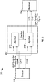
- FIG. 2 illustrates an encoder resolution reduction system 200.
- the system 200 may include one or more of an encoder 202, a recipient 204, a device 206, and an algorithm 208.
- the encoder 202 may correspond to, or be analogous to, the encoder 102 of FIG. 1 .
- the recipient 204 may correspond to, or be analogous to, the recipient 104 of FIG. 1 .
- the device 206 may correspond to, or be analogous to, the device 106 of FIG. 1 .
- the algorithm 208 may correspond to, or be analogous to, the algorithm 108 of FIG. 1 .
- the encoder 202 may generate and output two or more channels.
- the encoder is shown as outputting two channels, denoted as a first channel A and a second channel B.
- the two channels A and B output by the encoder may be of a relatively high resolution compared to an input interface associated with the recipient 204.
- the device 206 may be configured to reduce the resolution of the signals associated with channels A and B output by the encoder 202. Such a reduction in resolution may be performed by the algorithm 208.
- the algorithm 208 may be configured to generate and output or transmit the reduced resolution signals corresponding to channels A and B.
- the encoder 202 may include, or be associated with, two code tracks with sectors positioned ninety (90) degrees out of phase or two encoders so aligned with a single code track as to produce two output channel signals 90 degrees out of phase during periods of constant motion.
- the two output channels A and B of the encoder 202 may be used to detect a direction of movement of an entity the encoder 202 is applied to, such as a rotating motor.
- an algorithm 210 may be configured to perform such detection.
- the algorithm 210 may be configured to detect rising and/or falling edges of channels A and B output by the encoder 202, or voltage levels of channels A and B output by the encoder 202. Once detections of the channels are made, direction of movement may be made by applying logic. For example, a digital representation may be used, where a '0' may correspond to forward and a '1' may correspond to backward, or vice versa, so that the algorithm 208 may output quadrature outputs, potentially with a reduced resolution.
- the algorithms 208 and 210 may be implemented in a common component.
- FIG. 3 illustrates an exemplary resolution reduction device 300 for a dual channel (quadrature) encoder in accordance with one or more embodiments.
- the device 300 may correspond to the device 206 of FIG. 2 .
- a sample clock may correspond to a high frequency clock (e.g., 5 MHz) which may be used to synchronize two or more components (e.g., components 302, 304, 306, 308, and/or 310).
- Ch A input and Ch B input may correspond to optical encoder signals which may be in quadrature with one another.
- Ch A and Ch B may correspond to quadrature signals output by a factory test component 302.
- Filt A and Filt B may correspond to quadrature signals that are debounced or filtered to remove noise from the Ch A and Ch B signals.
- Up/Dwn may correspond to a signal that represents a direction of the quadrature pair (e.g., A and B, as reflected in Filt A and Filt B).
- Pulse may correspond to a signal that represents when a transition occurred on either of the Filt A and Filt B signals.
- Count value may correspond to, e.g., a nine (9) bit count value that represents the output of a modular or circular counter component 308.
- Ch A out and Ch B out may correspond to an encoded quadrature output of the counter component 308.
- a Reset signal may configure the components and signals in accordance with an initial or known state.
- the factory test component 302 may be configured to generate simulated versions of the Ch A input and Ch B input signals.
- the output generated by the factory test component 302 may be based on the state of Forward test and Reverse test signals.
- the simulated versions of the Ch A input and Ch B input signals generated by the factory test component 302 may be based on a slower clock frequency than the sample clock.
- the slower clock frequency may be obtained by dividing the sample clock by, e.g., one-hundred twenty-eight (128) as shown in FIG. 3 .
- the Ch A and Ch B signals output by the factory test component 302 may be a function of one or more test pins or test inputs (e.g., the Forward test and Reverse test signals), such that the factory test component 302 may be configured to pass the Ch A input and Ch B input signals to the sample and filter component 304 under one or more conditions.
- the factory test component 302 may include one or more multiplexors to selectively choose between passing the Ch A input and Ch B input signals versus outputting a simulated signal.
- the factory test component 302 may be used to test subsequent components, such as the components 304-310.
- a sample and filter component 304 may be configured to sample the Ch A and Ch B signals and output respective Filt A and Filt B signals.
- the Ch A and Ch B signals received at the sample and filter component 304 may be asynchronous, and the sample and filter component 304 may sample those signals and synchronize them with a system clock or the sample clock.
- the sample and filter component 304 may filter glitches from the Ch A and Ch B signals.
- the sample and filter component 304 may apply a two out of three (2/3) majority filter in some embodiments.
- a quadrature decoder component 306 may be configured to determine a direction of the quadrature input (e.g., forward or reverse), potentially in response to each transition of either Ch A or Ch B (as reflected in Filt A and Filt B, respectively). The determined direction may be output by the quadrature decoder component 306 in connection with the Up/Dwn signal. The quadrature decoder component 306 may create a single pulse for each transition in connection with the Pulse signal, so that the counter component 308 can count the event.
- a direction of the quadrature input e.g., forward or reverse
- the quadrature decoder component 306 may create a single pulse for each transition in connection with the Pulse signal, so that the counter component 308 can count the event.
- the counter component 308 may be configured to output the value of the count in connection with the Count value signal(s).
- An encode count to quadrature output component 310 may be configured to receive the Count value signal(s) and divide the count value into segments, such as four equal segments.
- the encode count to quadrature output component 310 may be configured to encode the quadrature outputs into, e.g., four states, potentially to ensure that the output signals will be a quadrature pair.
- the Count value signal(s) output by the counter component 308 might correspond to the Up/Dwn and Pulse signals.
- FIG. 4 illustrates a method that may be used in connection with one or more devices or systems, such as those described herein.
- the method of FIG. 4 may be used to generate and output one or more reduced resolution channels or signals.
- one or more channels or signals may be received.
- a device e.g., device 106 or device 206 may receive a channel or signal from an encoder (e.g., encoder 102 or encoder 202) at an input of the device.
- the received channel or signal may be of a high resolution, relative to a required for a low resolution channel or signal at an input interface associated with a recipient (e.g., recipient 104 or recipient 204).
- the device may execute a quadrature decoding algorithm (e.g., algorithm 210) to detect a direction of movement detect a direction of movement of an entity the encoder is applied to.
- the quadrature decoding algorithm may be based on a relative phase between two encoder pulse signals or channels (e.g., channels A and B as output by the encoder 202).
- the quadrature decoding algorithm may output the detected direction of movement to another algorithm, such as a resolution reduction algorithm (e.g., algorithm 108 or algorithm 208).
- the device may execute a resolution reduction algorithm to reduce the resolution associated with the channel or signal received in block 402.
- the resolution reduction algorithm may be based on a counter or a divide by 'N' process or routine.
- phasing may be maintained such that direction can be accurately inferred.
- the device may output the reduced resolution channel or signal, potentially for receipt by the recipient.
- the output reduced resolution channel or signal may include quadrature outputs with reduced resolution based on the direction information associated with block 404.
- FIG. 4 The method illustrated in connection with FIG. 4 is illustrative. In some embodiments, one or more of the blocks or operations (or portions thereof) may be optional. In some embodiments, the operations may execute in an order or sequence different from what is shown. In some embodiments, additional operations not shown may be included.
- Embodiments of the disclosure may reduce a resolution associated with an output channel or signal of an encoder.
- a high resolution encoder pulse channel or signal may be reduced in connection with one or more resolution reduction algorithms.
- Embodiments of the disclosure may achieve the reduction while minimizing cost. For example, some embodiments may leverage a low cost reflective encoder with high resolution in order to interface to a device that requires very low resolution encoder channels or signals.
- various functions or acts may take place at a given location and/or in connection with the operation of one or more apparatuses, systems, or devices. For example, in some embodiments, a portion of a given function or act may be performed at a first device or location, and the remainder of the function or act may be performed at one or more additional devices or locations.
- an apparatus or system may include one or more processors, and memory storing instructions that, when executed by the one or more processors, cause the apparatus or system to perform one or more methodological acts as described herein.
- Various mechanical components known to those of skill in the art may be used in some embodiments.
- instructions may be stored on one or more computer-readable media, such as a transitory and/or non-transitory computer-readable medium.
- the instructions when executed, may cause an entity (e.g., an apparatus or system) to perform one or more methodological acts as described herein.
- Embodiments may be tied to one or more particular machines.
- one or more architectures or devices may be configured to reduce a resolution of an encoder, such as a reflective encoder.
- the architectures or devices may maintain symmetry and quadrature data or information, which may be used to obtain information regarding a direction of movement.
Landscapes
- Engineering & Computer Science (AREA)
- Theoretical Computer Science (AREA)
- Automation & Control Theory (AREA)
- Computer Networks & Wireless Communication (AREA)
- Physics & Mathematics (AREA)
- General Physics & Mathematics (AREA)
- Transmission And Conversion Of Sensor Element Output (AREA)
- Optical Transform (AREA)
Claims (9)
- Verfahren zum Reduzieren der Auflösung von Signalen von einem Codierer (202) in einem Aufzugsystem (200), der Bewegungsrichtungen eines Aufzugs codiert, umfassend:Empfangen, durch eine Vorrichtung (206), von zwei gepulsten Signalen, die jeweils zwei Kanälen zugeordnet sind, wobei die Kanäle eine Ausgabe eines Codierers (202) umfassen;Ausführen, durch die Vorrichtung (206), eines ersten Algorithmus (210) zum Erkennen einer Bewegungsrichtung einer Einheit, auf die der Codierer (202) angewandt wird, auf Grundlage der zwei Signale;Ausführen, durch die Vorrichtung (206), eines zweiten Algorithmus (208) zum Erzeugen von zwei Signalen mit einer reduzierten Auflösung im Verhältnis zu der Auflösung der zwei Signale, die der Ausgabe des Codierers (202) zugeordnet sind, wobei die zwei Signale mit der reduzierten Auflösung die erkannte Bewegungsrichtung umfassen; undAusgeben, durch die Vorrichtung (206), der zwei Signale mit der reduzierten Auflösung;wobei:der erste Algorithmus (210) dazu konfiguriert ist, beim Erkennen der Bewegungsrichtung der Einheit, auf die der Codierer (202) angewandt wird, wenigstens eins von ansteigenden und abfallenden Flanken in den zwei Signalen zu erkennen, die der Ausgabe des Codierers (202) zugeordnet sind, oderwobei der erste Algorithmus (210) dazu konfiguriert ist, beim Erkennen der Bewegungsrichtung der Einheit, auf die der Codierer (202) angewandt wird, Spannungspegel der zwei Signale zu erkennen, die der Ausgabe des Codierers (202) zugeordnet sind;dadurch gekennzeichnet, dass:
der zweite Algorithmus (208) einen Zähler verwendet, der dazu konfiguriert ist, einen Impuls für jedes der zwei Signale mit der reduzierten Auflösung auf Grundlage dessen auszugeben, dass er eine Anzahl von Impulsen in einem entsprechenden der zwei Signale gezählt hat, die den zwei Kanälen zugeordnet sind, die die Ausgabe des Codierers (202) umfassen. - Verfahren nach Anspruch 1, wobei die Einheit, auf die der Codierer (202) angewandt wird, ein Drehmotor ist.
- Verfahren nach einem der vorangehenden Ansprüche, ferner umfassend:
Ausgeben, durch die Vorrichtung (206), der zwei Signale mit der reduzierten Auflösung zum Empfang durch ein Aufzugrettungssystem. - System (200) zum Reduzieren der Auflösung von Signalen von einem Codierer (202) in einem Aufzugsystem (200), der Bewegungsrichtungen eines Aufzugs codiert, umfassend:einen Codierer (202), der dazu konfiguriert ist, zwei Signale auszugeben; undeine Rechenvorrichtung, die für Folgendes konfiguriert ist:Empfangen (402) der von dem Codierer (202) ausgegebenen zwei Signale,Erkennen einer Bewegungsrichtung einer Einheit, auf die der Codierer (202) angewandt wird, auf Grundlage der zwei Signale,Erzeugen von zwei Signalen mit einer reduzierten Auflösung im Verhältnis zu der Auflösung der zwei Signale, die der Ausgabe des Codierers (202) zugeordnet sind, wobei die zwei Signale mit der reduzierten Auflösung die erkannte Bewegungsrichtung umfassen, undAusgeben der zwei Signale mit der reduzierten Auflösung;wobei:die Rechenvorrichtung dazu konfiguriert ist, beim Erkennen der Bewegungsrichtung der Einheit, auf die der Codierer (202) angewandt wird, wenigstens eins von ansteigenden und abfallenden Flanken in den zwei Kanälen zu erkennen, die von dem Codierer (202) ausgegeben werden, oderdie Rechenvorrichtung dazu konfiguriert ist, beim Erkennen der Bewegungsrichtung der Einheit, auf die der Codierer (202) angewandt wird, Spannungspegel der zwei Kanäle zu erkennen, die von dem Codierer (202) ausgegeben werden;dadurch gekennzeichnet, dass:
die Rechenvorrichtung einen Zähler umfasst, der dazu konfiguriert ist, einen Impuls für jedes der zwei Signale mit der reduzierten Auflösung auf Grundlage dessen auszugeben, dass er eine Anzahl von Impulsen in einem entsprechenden der zwei Signale gezählt hat, die von dem Codierer (202) ausgegeben werden. - System (200) nach Anspruch 4, wobei die Rechenvorrichtung wenigstens eins der Folgenden umfasst: eine komplexe programmierbare Logikvorrichtung (CPLD), ein feldprogrammierbares Gate-Array (FPGA) und einen Mikroprozessor/Mikrocontroller.
- System (200) nach Anspruch 4 oder 5, wobei der Codierer (202) einen reflektierenden Codierer umfasst.
- System (200) nach einem der Ansprüche 4 bis 6, wobei die Rechenvorrichtung dazu konfiguriert ist, einen Impuls in Reaktion auf einen Übergang in einem der Signalausgänge des Codierers (202) zu erzeugen;
und wobei die Rechenvorrichtung Folgendes umfasst:eine Modulo-Zählerkomponente (308), die dazu konfiguriert ist, in Reaktion auf den Impuls erhöht zu werden, wenn die Bewegungsrichtung einer ersten Richtung entspricht, und verringert zu werden, wenn die Bewegungsrichtung einer zweiten Richtung entspricht; undeine Quadraturausgabekomponente (310), die dazu konfiguriert ist, eine Zählerausgabe des Modulo-Zählers in eine Vielzahl von Segmenten zu teilen und ein Paar Quadraturausgangssignale zu erzeugen. - System (200) nach Anspruch 7, ferner umfassend:eine Filterkomponente (304), die dazu konfiguriert ist, Störimpulse, die den Ausgangssignalen des Codierers (202) zugeordnet sind, zu filtern; undeine Werksprüfkomponente (302), die dazu konfiguriert ist, selektiv eins der Folgenden auszugeben: die Ausgangssignale des Codierers (202) und simulierte Quadratursignale in Abhängigkeit von einem oder mehreren Prüfstiften oder Testeingängen.
- System (200) nach Anspruch 8, wobei die Modulo-Zählerkomponente (308), die Quadraturausgabekomponente (310), die Filterkomponente (304) und die Werksprüfkomponente (302) dazu konfiguriert sind, mittels eines Taktgebers miteinander synchronisiert zu sein, und wobei die Werksprüfkomponente (302) dazu konfiguriert ist, die simulierten Quadratursignale auf Grundlage einer Division (128) des Taktgebers zu erzeugen.
Applications Claiming Priority (1)
| Application Number | Priority Date | Filing Date | Title |
|---|---|---|---|
| PCT/US2013/022079 WO2014113015A1 (en) | 2013-01-18 | 2013-01-18 | Encoder resolution reduction |
Publications (3)
| Publication Number | Publication Date |
|---|---|
| EP2946476A1 EP2946476A1 (de) | 2015-11-25 |
| EP2946476A4 EP2946476A4 (de) | 2016-08-10 |
| EP2946476B1 true EP2946476B1 (de) | 2019-09-11 |
Family
ID=51209964
Family Applications (1)
| Application Number | Title | Priority Date | Filing Date |
|---|---|---|---|
| EP13872262.4A Active EP2946476B1 (de) | 2013-01-18 | 2013-01-18 | Codiererauflösungsreduzierung |
Country Status (5)
| Country | Link |
|---|---|
| US (1) | US9979412B2 (de) |
| EP (1) | EP2946476B1 (de) |
| CN (2) | CN104919710A (de) |
| ES (1) | ES2746750T3 (de) |
| WO (1) | WO2014113015A1 (de) |
Families Citing this family (4)
| Publication number | Priority date | Publication date | Assignee | Title |
|---|---|---|---|---|
| US20160381349A1 (en) * | 2015-06-29 | 2016-12-29 | Redrover Co., Ltd. | System for controlling camera rig for capturing stereographic image having low signal processing error rate |
| CN109213109A (zh) * | 2017-06-29 | 2019-01-15 | 沈阳新松机器人自动化股份有限公司 | 编码器分辨率检测方法 |
| EP3650389B1 (de) | 2018-11-12 | 2023-12-27 | Otis Elevator Company | Verfahren und vorrichtung zur überwachung eines aufzugsystems |
| IT202200006461A1 (it) * | 2022-04-01 | 2023-10-01 | St Microelectronics Rousset | Circuiti e procedimenti per effettuare il debouncing di segnali prodotti da un trasduttore di posizione angolare |
Citations (3)
| Publication number | Priority date | Publication date | Assignee | Title |
|---|---|---|---|---|
| US4831510A (en) * | 1987-09-17 | 1989-05-16 | Allen-Bradley Company, Inc. | Encoder and resolver signal processing circuit |
| US20030184248A1 (en) * | 2002-03-27 | 2003-10-02 | Brother Kogyo Kabushiki Kaisha | Apparatus and method for controlling an electric motor |
| US6704683B1 (en) * | 1998-04-28 | 2004-03-09 | Immersion Corporation | Direct velocity estimation for encoders using nonlinear period measurement |
Family Cites Families (24)
| Publication number | Priority date | Publication date | Assignee | Title |
|---|---|---|---|---|
| US5274203A (en) * | 1989-06-30 | 1993-12-28 | Otis Elevator Company | "Smart" position transducer system for elevators |
| US5021781A (en) * | 1989-10-18 | 1991-06-04 | Pitney Bowes Inc. | Two stage quadrature incremental encoder |
| US5130710A (en) * | 1989-10-18 | 1992-07-14 | Pitney Bowes Inc. | Microcomputer-controlled electronic postage meter having print wheels set by separate D.C. motors |
| GB9506338D0 (en) * | 1995-03-28 | 1995-05-17 | Switched Reluctance Drives Ltd | Improved position encoder |
| US5939712A (en) * | 1997-05-30 | 1999-08-17 | Hewlett-Packard Company | Absolute position detection within 1 revolution using 3-channel incremental encoders with high resolution index track |
| WO2001092894A2 (en) | 2000-05-31 | 2001-12-06 | Otis Elevator Company | Integrated speed sensor for elevator application |
| US6407683B1 (en) * | 2000-07-27 | 2002-06-18 | Tyco Electronics Logistics Ag | Optimized performance incremental encoder with error detection capability |
| US20040129869A1 (en) * | 2000-10-22 | 2004-07-08 | Lennart Stridsberg | Position transducer |
| KR100376720B1 (ko) * | 2000-12-30 | 2003-03-17 | 현대자동차주식회사 | 인코더 신호 모의 생성장치 및 그 방법 |
| EP1308888A1 (de) | 2001-11-06 | 2003-05-07 | STMicroelectronics S.r.l. | Digitales Bildverarbeitungsverfahren |
| CN2604262Y (zh) * | 2003-02-18 | 2004-02-25 | 童自惠 | 数控飞锯机组用半闭环、全闭环兼容的位置控制系统 |
| US20050238365A1 (en) * | 2004-04-22 | 2005-10-27 | Tan Boon K | Optical encoder providing a wide range of resolutions |
| TWI282954B (en) * | 2004-10-22 | 2007-06-21 | Benq Corp | Apparatus and method for improving resolution of optical encoder |
| JP4879911B2 (ja) * | 2005-01-11 | 2012-02-22 | オーチス エレベータ カンパニー | エレベータ救出システムを備えるエレベータ |
| JP4857285B2 (ja) * | 2005-01-11 | 2012-01-18 | オーチス エレベータ カンパニー | エレベータの救出運転を行う方法 |
| DE102006048851A1 (de) * | 2006-10-16 | 2008-04-17 | Siemens Ag | Vorrichtung und Verfahren zur Erfassung einer Position einer Antriebseinheit |
| CN101046394B (zh) * | 2007-03-23 | 2010-07-21 | 北京科技大学 | 一种高精度磁编码器用磁鼓的制备方法 |
| RU2484003C2 (ru) * | 2008-07-25 | 2013-06-10 | Отис Элевэйтор Компани | Способ эксплуатации лифта в аварийном режиме |
| WO2010138155A2 (en) * | 2009-05-27 | 2010-12-02 | Active Precision, Inc. | Encoder interpolator with enhanced precision |
| US8330098B2 (en) * | 2010-07-07 | 2012-12-11 | Avago Technologies Ecbu Ip (Singapore) Pte. Ltd. | High resolution, high speed, miniaturized optical encoder |
| US8772705B2 (en) * | 2010-12-01 | 2014-07-08 | Avago Technologies General Ip (Singapore) Pte. Ltd. | Interpolation circuitry for optical encoders |
| JP5849395B2 (ja) * | 2011-01-24 | 2016-01-27 | セイコーエプソン株式会社 | 記録方法及び記録装置 |
| CN102840874A (zh) * | 2011-06-22 | 2012-12-26 | 合康变频科技(武汉)有限公司 | 正交光电编码器的任意整数分频方法及系统 |
| US9484060B2 (en) * | 2013-08-19 | 2016-11-01 | Canon Kabushiki Kaisha | Encoder |
-
2013
- 2013-01-18 US US14/760,897 patent/US9979412B2/en active Active
- 2013-01-18 ES ES13872262T patent/ES2746750T3/es active Active
- 2013-01-18 WO PCT/US2013/022079 patent/WO2014113015A1/en not_active Ceased
- 2013-01-18 CN CN201380070666.8A patent/CN104919710A/zh active Pending
- 2013-01-18 EP EP13872262.4A patent/EP2946476B1/de active Active
- 2013-01-18 CN CN202210121435.6A patent/CN114674350A/zh active Pending
Patent Citations (3)
| Publication number | Priority date | Publication date | Assignee | Title |
|---|---|---|---|---|
| US4831510A (en) * | 1987-09-17 | 1989-05-16 | Allen-Bradley Company, Inc. | Encoder and resolver signal processing circuit |
| US6704683B1 (en) * | 1998-04-28 | 2004-03-09 | Immersion Corporation | Direct velocity estimation for encoders using nonlinear period measurement |
| US20030184248A1 (en) * | 2002-03-27 | 2003-10-02 | Brother Kogyo Kabushiki Kaisha | Apparatus and method for controlling an electric motor |
Non-Patent Citations (2)
| Title |
|---|
| ANONYMOUS: "Angular Position Measurement with a Quadrature Encoder", DISCUSSION FORUMS - NATIONAL INSTRUMENTS, 10 August 2011 (2011-08-10), XP055478175, Retrieved from the Internet <URL:https://forums.ni.com/t5/NI-ELVIS-II-and-myDAQ/Angular-Position-Measurement-with-a-Quadrature-Encoder/ta-p/3496226> [retrieved on 20180524] * |
| ARMANDO NAVA ET AL: "course/real-time-digital-signal-processing/ Demo: Real-time Edge-Detection-Based Motion Tracking", 28 December 2012 (2012-12-28), XP055478293, Retrieved from the Internet <URL:http://www.comm.utoronto.ca/~dkundur/course_info/real-time-DSP/implementation/Demo_Vid_Edge_Motion_Track.pdf> [retrieved on 20180524] * |
Also Published As
| Publication number | Publication date |
|---|---|
| US9979412B2 (en) | 2018-05-22 |
| ES2746750T3 (es) | 2020-03-06 |
| WO2014113015A1 (en) | 2014-07-24 |
| CN114674350A (zh) | 2022-06-28 |
| CN104919710A (zh) | 2015-09-16 |
| US20150365103A1 (en) | 2015-12-17 |
| EP2946476A1 (de) | 2015-11-25 |
| EP2946476A4 (de) | 2016-08-10 |
Similar Documents
| Publication | Publication Date | Title |
|---|---|---|
| EP2946476B1 (de) | Codiererauflösungsreduzierung | |
| JP2013190327A (ja) | ロータリーエンコーダの監視装置および監視方法 | |
| CN103365757B (zh) | 时钟检测方法及装置 | |
| US9310226B2 (en) | Position detection apparatus, drive control apparatus, and lens apparatus | |
| US8705687B2 (en) | Input circuit in high speed counter module in PLC | |
| JP2007293682A (ja) | クロック異常検出回路、及びクロック異常検出方法 | |
| ES2370429T3 (es) | Dispositivo y método para la detección de una posición de una unidad motriz. | |
| US9361788B2 (en) | Receiver of remote control device | |
| EP1598643B1 (de) | Fehlerkorrekturschaltung für einen Codierer | |
| JP4175226B2 (ja) | エンコーダ通信異常検出装置 | |
| US20150180478A1 (en) | Apparatus for simplification of input signal | |
| US20060049964A1 (en) | Dual optical angular encoder | |
| US8867684B2 (en) | Low latency synchronizer circuit | |
| JP4651984B2 (ja) | エンコーダカウンタ | |
| US20190137302A1 (en) | Device for determining the movement of a rotary element, particularly for readings of water and/or gas meters | |
| US7535382B2 (en) | High speed quadrature counter | |
| CN104821771B (zh) | 基于cpld的光电码盘正交分频方法 | |
| JP4631427B2 (ja) | 回転速度検出器の故障検出装置 | |
| CN115085875B (zh) | 一种双编码器实现安全备份的装置及方法 | |
| EP3617661B1 (de) | Absolutpositiondetektionsvorrichtung und -verfahren und computerprogramm | |
| JP2013187715A (ja) | クロック監視装置 | |
| RU2481619C1 (ru) | Устройство резервирования | |
| US6859912B2 (en) | Method and circuit arrangement for clock recovery | |
| RU2430464C2 (ru) | Пересчетное устройство с частотно-фазовой схемой сравнения | |
| SU1282254A1 (ru) | Устройство дл сравнени фаз |
Legal Events
| Date | Code | Title | Description |
|---|---|---|---|
| PUAI | Public reference made under article 153(3) epc to a published international application that has entered the european phase |
Free format text: ORIGINAL CODE: 0009012 |
|
| 17P | Request for examination filed |
Effective date: 20150806 |
|
| AK | Designated contracting states |
Kind code of ref document: A1 Designated state(s): AL AT BE BG CH CY CZ DE DK EE ES FI FR GB GR HR HU IE IS IT LI LT LU LV MC MK MT NL NO PL PT RO RS SE SI SK SM TR |
|
| AX | Request for extension of the european patent |
Extension state: BA ME |
|
| RIN1 | Information on inventor provided before grant (corrected) |
Inventor name: VERONESI, WILLIAM, A. Inventor name: MARVIN, DARYL, J. Inventor name: KANG, KEUNMO Inventor name: CULP, SLADE, R. Inventor name: BOGLI, CRAIG, DREW |
|
| DAX | Request for extension of the european patent (deleted) | ||
| A4 | Supplementary search report drawn up and despatched |
Effective date: 20160712 |
|
| RIC1 | Information provided on ipc code assigned before grant |
Ipc: H03M 7/30 20060101ALI20160706BHEP Ipc: H03M 5/02 20060101ALI20160706BHEP Ipc: H03M 1/22 20060101AFI20160706BHEP |
|
| RAP1 | Party data changed (applicant data changed or rights of an application transferred) |
Owner name: OTIS ELEVATOR COMPANY |
|
| STAA | Information on the status of an ep patent application or granted ep patent |
Free format text: STATUS: EXAMINATION IS IN PROGRESS |
|
| 17Q | First examination report despatched |
Effective date: 20180601 |
|
| REG | Reference to a national code |
Ref country code: DE Ref legal event code: R079 Ref document number: 602013060529 Country of ref document: DE Free format text: PREVIOUS MAIN CLASS: H03M0001220000 Ipc: H03M0005020000 |
|
| GRAP | Despatch of communication of intention to grant a patent |
Free format text: ORIGINAL CODE: EPIDOSNIGR1 |
|
| STAA | Information on the status of an ep patent application or granted ep patent |
Free format text: STATUS: GRANT OF PATENT IS INTENDED |
|
| RIC1 | Information provided on ipc code assigned before grant |
Ipc: H03M 1/22 20060101ALI20190227BHEP Ipc: H03M 5/02 20060101AFI20190227BHEP Ipc: H03M 7/22 20060101ALI20190227BHEP Ipc: B66B 1/34 20060101ALI20190227BHEP |
|
| INTG | Intention to grant announced |
Effective date: 20190322 |
|
| GRAS | Grant fee paid |
Free format text: ORIGINAL CODE: EPIDOSNIGR3 |
|
| GRAA | (expected) grant |
Free format text: ORIGINAL CODE: 0009210 |
|
| STAA | Information on the status of an ep patent application or granted ep patent |
Free format text: STATUS: THE PATENT HAS BEEN GRANTED |
|
| AK | Designated contracting states |
Kind code of ref document: B1 Designated state(s): AL AT BE BG CH CY CZ DE DK EE ES FI FR GB GR HR HU IE IS IT LI LT LU LV MC MK MT NL NO PL PT RO RS SE SI SK SM TR |
|
| REG | Reference to a national code |
Ref country code: GB Ref legal event code: FG4D |
|
| REG | Reference to a national code |
Ref country code: CH Ref legal event code: EP |
|
| REG | Reference to a national code |
Ref country code: AT Ref legal event code: REF Ref document number: 1179831 Country of ref document: AT Kind code of ref document: T Effective date: 20190915 |
|
| REG | Reference to a national code |
Ref country code: DE Ref legal event code: R096 Ref document number: 602013060529 Country of ref document: DE Ref country code: IE Ref legal event code: FG4D |
|
| REG | Reference to a national code |
Ref country code: NL Ref legal event code: MP Effective date: 20190911 |
|
| REG | Reference to a national code |
Ref country code: LT Ref legal event code: MG4D |
|
| PG25 | Lapsed in a contracting state [announced via postgrant information from national office to epo] |
Ref country code: SE Free format text: LAPSE BECAUSE OF FAILURE TO SUBMIT A TRANSLATION OF THE DESCRIPTION OR TO PAY THE FEE WITHIN THE PRESCRIBED TIME-LIMIT Effective date: 20190911 Ref country code: NO Free format text: LAPSE BECAUSE OF FAILURE TO SUBMIT A TRANSLATION OF THE DESCRIPTION OR TO PAY THE FEE WITHIN THE PRESCRIBED TIME-LIMIT Effective date: 20191211 Ref country code: FI Free format text: LAPSE BECAUSE OF FAILURE TO SUBMIT A TRANSLATION OF THE DESCRIPTION OR TO PAY THE FEE WITHIN THE PRESCRIBED TIME-LIMIT Effective date: 20190911 Ref country code: LT Free format text: LAPSE BECAUSE OF FAILURE TO SUBMIT A TRANSLATION OF THE DESCRIPTION OR TO PAY THE FEE WITHIN THE PRESCRIBED TIME-LIMIT Effective date: 20190911 Ref country code: HR Free format text: LAPSE BECAUSE OF FAILURE TO SUBMIT A TRANSLATION OF THE DESCRIPTION OR TO PAY THE FEE WITHIN THE PRESCRIBED TIME-LIMIT Effective date: 20190911 Ref country code: BG Free format text: LAPSE BECAUSE OF FAILURE TO SUBMIT A TRANSLATION OF THE DESCRIPTION OR TO PAY THE FEE WITHIN THE PRESCRIBED TIME-LIMIT Effective date: 20191211 |
|
| PG25 | Lapsed in a contracting state [announced via postgrant information from national office to epo] |
Ref country code: AL Free format text: LAPSE BECAUSE OF FAILURE TO SUBMIT A TRANSLATION OF THE DESCRIPTION OR TO PAY THE FEE WITHIN THE PRESCRIBED TIME-LIMIT Effective date: 20190911 Ref country code: LV Free format text: LAPSE BECAUSE OF FAILURE TO SUBMIT A TRANSLATION OF THE DESCRIPTION OR TO PAY THE FEE WITHIN THE PRESCRIBED TIME-LIMIT Effective date: 20190911 Ref country code: RS Free format text: LAPSE BECAUSE OF FAILURE TO SUBMIT A TRANSLATION OF THE DESCRIPTION OR TO PAY THE FEE WITHIN THE PRESCRIBED TIME-LIMIT Effective date: 20190911 Ref country code: GR Free format text: LAPSE BECAUSE OF FAILURE TO SUBMIT A TRANSLATION OF THE DESCRIPTION OR TO PAY THE FEE WITHIN THE PRESCRIBED TIME-LIMIT Effective date: 20191212 |
|
| REG | Reference to a national code |
Ref country code: ES Ref legal event code: FG2A Ref document number: 2746750 Country of ref document: ES Kind code of ref document: T3 Effective date: 20200306 |
|
| REG | Reference to a national code |
Ref country code: AT Ref legal event code: MK05 Ref document number: 1179831 Country of ref document: AT Kind code of ref document: T Effective date: 20190911 |
|
| PG25 | Lapsed in a contracting state [announced via postgrant information from national office to epo] |
Ref country code: RO Free format text: LAPSE BECAUSE OF FAILURE TO SUBMIT A TRANSLATION OF THE DESCRIPTION OR TO PAY THE FEE WITHIN THE PRESCRIBED TIME-LIMIT Effective date: 20190911 Ref country code: PL Free format text: LAPSE BECAUSE OF FAILURE TO SUBMIT A TRANSLATION OF THE DESCRIPTION OR TO PAY THE FEE WITHIN THE PRESCRIBED TIME-LIMIT Effective date: 20190911 Ref country code: PT Free format text: LAPSE BECAUSE OF FAILURE TO SUBMIT A TRANSLATION OF THE DESCRIPTION OR TO PAY THE FEE WITHIN THE PRESCRIBED TIME-LIMIT Effective date: 20200113 Ref country code: NL Free format text: LAPSE BECAUSE OF FAILURE TO SUBMIT A TRANSLATION OF THE DESCRIPTION OR TO PAY THE FEE WITHIN THE PRESCRIBED TIME-LIMIT Effective date: 20190911 Ref country code: AT Free format text: LAPSE BECAUSE OF FAILURE TO SUBMIT A TRANSLATION OF THE DESCRIPTION OR TO PAY THE FEE WITHIN THE PRESCRIBED TIME-LIMIT Effective date: 20190911 Ref country code: EE Free format text: LAPSE BECAUSE OF FAILURE TO SUBMIT A TRANSLATION OF THE DESCRIPTION OR TO PAY THE FEE WITHIN THE PRESCRIBED TIME-LIMIT Effective date: 20190911 Ref country code: IT Free format text: LAPSE BECAUSE OF FAILURE TO SUBMIT A TRANSLATION OF THE DESCRIPTION OR TO PAY THE FEE WITHIN THE PRESCRIBED TIME-LIMIT Effective date: 20190911 |
|
| PG25 | Lapsed in a contracting state [announced via postgrant information from national office to epo] |
Ref country code: IS Free format text: LAPSE BECAUSE OF FAILURE TO SUBMIT A TRANSLATION OF THE DESCRIPTION OR TO PAY THE FEE WITHIN THE PRESCRIBED TIME-LIMIT Effective date: 20200224 Ref country code: CZ Free format text: LAPSE BECAUSE OF FAILURE TO SUBMIT A TRANSLATION OF THE DESCRIPTION OR TO PAY THE FEE WITHIN THE PRESCRIBED TIME-LIMIT Effective date: 20190911 Ref country code: SM Free format text: LAPSE BECAUSE OF FAILURE TO SUBMIT A TRANSLATION OF THE DESCRIPTION OR TO PAY THE FEE WITHIN THE PRESCRIBED TIME-LIMIT Effective date: 20190911 Ref country code: SK Free format text: LAPSE BECAUSE OF FAILURE TO SUBMIT A TRANSLATION OF THE DESCRIPTION OR TO PAY THE FEE WITHIN THE PRESCRIBED TIME-LIMIT Effective date: 20190911 |
|
| REG | Reference to a national code |
Ref country code: DE Ref legal event code: R097 Ref document number: 602013060529 Country of ref document: DE |
|
| PLBE | No opposition filed within time limit |
Free format text: ORIGINAL CODE: 0009261 |
|
| STAA | Information on the status of an ep patent application or granted ep patent |
Free format text: STATUS: NO OPPOSITION FILED WITHIN TIME LIMIT |
|
| PG2D | Information on lapse in contracting state deleted |
Ref country code: IS |
|
| PG25 | Lapsed in a contracting state [announced via postgrant information from national office to epo] |
Ref country code: DK Free format text: LAPSE BECAUSE OF FAILURE TO SUBMIT A TRANSLATION OF THE DESCRIPTION OR TO PAY THE FEE WITHIN THE PRESCRIBED TIME-LIMIT Effective date: 20190911 Ref country code: IS Free format text: LAPSE BECAUSE OF FAILURE TO SUBMIT A TRANSLATION OF THE DESCRIPTION OR TO PAY THE FEE WITHIN THE PRESCRIBED TIME-LIMIT Effective date: 20200112 |
|
| 26N | No opposition filed |
Effective date: 20200615 |
|
| PG25 | Lapsed in a contracting state [announced via postgrant information from national office to epo] |
Ref country code: MC Free format text: LAPSE BECAUSE OF FAILURE TO SUBMIT A TRANSLATION OF THE DESCRIPTION OR TO PAY THE FEE WITHIN THE PRESCRIBED TIME-LIMIT Effective date: 20190911 Ref country code: SI Free format text: LAPSE BECAUSE OF FAILURE TO SUBMIT A TRANSLATION OF THE DESCRIPTION OR TO PAY THE FEE WITHIN THE PRESCRIBED TIME-LIMIT Effective date: 20190911 |
|
| REG | Reference to a national code |
Ref country code: CH Ref legal event code: PL |
|
| REG | Reference to a national code |
Ref country code: BE Ref legal event code: MM Effective date: 20200131 |
|
| PG25 | Lapsed in a contracting state [announced via postgrant information from national office to epo] |
Ref country code: LU Free format text: LAPSE BECAUSE OF NON-PAYMENT OF DUE FEES Effective date: 20200118 |
|
| PG25 | Lapsed in a contracting state [announced via postgrant information from national office to epo] |
Ref country code: CH Free format text: LAPSE BECAUSE OF NON-PAYMENT OF DUE FEES Effective date: 20200131 Ref country code: LI Free format text: LAPSE BECAUSE OF NON-PAYMENT OF DUE FEES Effective date: 20200131 Ref country code: BE Free format text: LAPSE BECAUSE OF NON-PAYMENT OF DUE FEES Effective date: 20200131 |
|
| PG25 | Lapsed in a contracting state [announced via postgrant information from national office to epo] |
Ref country code: IE Free format text: LAPSE BECAUSE OF NON-PAYMENT OF DUE FEES Effective date: 20200118 |
|
| PG25 | Lapsed in a contracting state [announced via postgrant information from national office to epo] |
Ref country code: TR Free format text: LAPSE BECAUSE OF FAILURE TO SUBMIT A TRANSLATION OF THE DESCRIPTION OR TO PAY THE FEE WITHIN THE PRESCRIBED TIME-LIMIT Effective date: 20190911 Ref country code: MT Free format text: LAPSE BECAUSE OF FAILURE TO SUBMIT A TRANSLATION OF THE DESCRIPTION OR TO PAY THE FEE WITHIN THE PRESCRIBED TIME-LIMIT Effective date: 20190911 Ref country code: CY Free format text: LAPSE BECAUSE OF FAILURE TO SUBMIT A TRANSLATION OF THE DESCRIPTION OR TO PAY THE FEE WITHIN THE PRESCRIBED TIME-LIMIT Effective date: 20190911 |
|
| PG25 | Lapsed in a contracting state [announced via postgrant information from national office to epo] |
Ref country code: MK Free format text: LAPSE BECAUSE OF FAILURE TO SUBMIT A TRANSLATION OF THE DESCRIPTION OR TO PAY THE FEE WITHIN THE PRESCRIBED TIME-LIMIT Effective date: 20190911 |
|
| PGFP | Annual fee paid to national office [announced via postgrant information from national office to epo] |
Ref country code: GB Payment date: 20251217 Year of fee payment: 14 |
|
| PGFP | Annual fee paid to national office [announced via postgrant information from national office to epo] |
Ref country code: FR Payment date: 20251217 Year of fee payment: 14 |
|
| PGFP | Annual fee paid to national office [announced via postgrant information from national office to epo] |
Ref country code: ES Payment date: 20260202 Year of fee payment: 14 |
|
| PGFP | Annual fee paid to national office [announced via postgrant information from national office to epo] |
Ref country code: DE Payment date: 20251217 Year of fee payment: 14 |