EP3617661B1 - Absolutpositiondetektionsvorrichtung und -verfahren und computerprogramm - Google Patents
Absolutpositiondetektionsvorrichtung und -verfahren und computerprogramm Download PDFInfo
- Publication number
- EP3617661B1 EP3617661B1 EP19193598.0A EP19193598A EP3617661B1 EP 3617661 B1 EP3617661 B1 EP 3617661B1 EP 19193598 A EP19193598 A EP 19193598A EP 3617661 B1 EP3617661 B1 EP 3617661B1
- Authority
- EP
- European Patent Office
- Prior art keywords
- signal
- absolute position
- relative movement
- signals
- phase difference
- Prior art date
- Legal status (The legal status is an assumption and is not a legal conclusion. Google has not performed a legal analysis and makes no representation as to the accuracy of the status listed.)
- Active
Links
Images






Classifications
-
- G—PHYSICS
- G01—MEASURING; TESTING
- G01D—MEASURING NOT SPECIALLY ADAPTED FOR A SPECIFIC VARIABLE; ARRANGEMENTS FOR MEASURING TWO OR MORE VARIABLES NOT COVERED IN A SINGLE OTHER SUBCLASS; TARIFF METERING APPARATUS; MEASURING OR TESTING NOT OTHERWISE PROVIDED FOR
- G01D5/00—Mechanical means for transferring the output of a sensing member; Means for converting the output of a sensing member to another variable where the form or nature of the sensing member does not constrain the means for converting; Transducers not specially adapted for a specific variable
- G01D5/26—Mechanical means for transferring the output of a sensing member; Means for converting the output of a sensing member to another variable where the form or nature of the sensing member does not constrain the means for converting; Transducers not specially adapted for a specific variable characterised by optical transfer means, i.e. using infrared, visible, or ultraviolet light
- G01D5/32—Mechanical means for transferring the output of a sensing member; Means for converting the output of a sensing member to another variable where the form or nature of the sensing member does not constrain the means for converting; Transducers not specially adapted for a specific variable characterised by optical transfer means, i.e. using infrared, visible, or ultraviolet light with attenuation or whole or partial obturation of beams of light
- G01D5/34—Mechanical means for transferring the output of a sensing member; Means for converting the output of a sensing member to another variable where the form or nature of the sensing member does not constrain the means for converting; Transducers not specially adapted for a specific variable characterised by optical transfer means, i.e. using infrared, visible, or ultraviolet light with attenuation or whole or partial obturation of beams of light the beams of light being detected by photocells
- G01D5/347—Mechanical means for transferring the output of a sensing member; Means for converting the output of a sensing member to another variable where the form or nature of the sensing member does not constrain the means for converting; Transducers not specially adapted for a specific variable characterised by optical transfer means, i.e. using infrared, visible, or ultraviolet light with attenuation or whole or partial obturation of beams of light the beams of light being detected by photocells using displacement encoding scales
- G01D5/34776—Absolute encoders with analogue or digital scales
- G01D5/34792—Absolute encoders with analogue or digital scales with only digital scales or both digital and incremental scales
-
- G—PHYSICS
- G01—MEASURING; TESTING
- G01D—MEASURING NOT SPECIALLY ADAPTED FOR A SPECIFIC VARIABLE; ARRANGEMENTS FOR MEASURING TWO OR MORE VARIABLES NOT COVERED IN A SINGLE OTHER SUBCLASS; TARIFF METERING APPARATUS; MEASURING OR TESTING NOT OTHERWISE PROVIDED FOR
- G01D5/00—Mechanical means for transferring the output of a sensing member; Means for converting the output of a sensing member to another variable where the form or nature of the sensing member does not constrain the means for converting; Transducers not specially adapted for a specific variable
- G01D5/26—Mechanical means for transferring the output of a sensing member; Means for converting the output of a sensing member to another variable where the form or nature of the sensing member does not constrain the means for converting; Transducers not specially adapted for a specific variable characterised by optical transfer means, i.e. using infrared, visible, or ultraviolet light
- G01D5/32—Mechanical means for transferring the output of a sensing member; Means for converting the output of a sensing member to another variable where the form or nature of the sensing member does not constrain the means for converting; Transducers not specially adapted for a specific variable characterised by optical transfer means, i.e. using infrared, visible, or ultraviolet light with attenuation or whole or partial obturation of beams of light
- G01D5/34—Mechanical means for transferring the output of a sensing member; Means for converting the output of a sensing member to another variable where the form or nature of the sensing member does not constrain the means for converting; Transducers not specially adapted for a specific variable characterised by optical transfer means, i.e. using infrared, visible, or ultraviolet light with attenuation or whole or partial obturation of beams of light the beams of light being detected by photocells
- G01D5/347—Mechanical means for transferring the output of a sensing member; Means for converting the output of a sensing member to another variable where the form or nature of the sensing member does not constrain the means for converting; Transducers not specially adapted for a specific variable characterised by optical transfer means, i.e. using infrared, visible, or ultraviolet light with attenuation or whole or partial obturation of beams of light the beams of light being detected by photocells using displacement encoding scales
- G01D5/3473—Circular or rotary encoders
-
- G—PHYSICS
- G01—MEASURING; TESTING
- G01D—MEASURING NOT SPECIALLY ADAPTED FOR A SPECIFIC VARIABLE; ARRANGEMENTS FOR MEASURING TWO OR MORE VARIABLES NOT COVERED IN A SINGLE OTHER SUBCLASS; TARIFF METERING APPARATUS; MEASURING OR TESTING NOT OTHERWISE PROVIDED FOR
- G01D5/00—Mechanical means for transferring the output of a sensing member; Means for converting the output of a sensing member to another variable where the form or nature of the sensing member does not constrain the means for converting; Transducers not specially adapted for a specific variable
- G01D5/26—Mechanical means for transferring the output of a sensing member; Means for converting the output of a sensing member to another variable where the form or nature of the sensing member does not constrain the means for converting; Transducers not specially adapted for a specific variable characterised by optical transfer means, i.e. using infrared, visible, or ultraviolet light
- G01D5/32—Mechanical means for transferring the output of a sensing member; Means for converting the output of a sensing member to another variable where the form or nature of the sensing member does not constrain the means for converting; Transducers not specially adapted for a specific variable characterised by optical transfer means, i.e. using infrared, visible, or ultraviolet light with attenuation or whole or partial obturation of beams of light
- G01D5/34—Mechanical means for transferring the output of a sensing member; Means for converting the output of a sensing member to another variable where the form or nature of the sensing member does not constrain the means for converting; Transducers not specially adapted for a specific variable characterised by optical transfer means, i.e. using infrared, visible, or ultraviolet light with attenuation or whole or partial obturation of beams of light the beams of light being detected by photocells
- G01D5/347—Mechanical means for transferring the output of a sensing member; Means for converting the output of a sensing member to another variable where the form or nature of the sensing member does not constrain the means for converting; Transducers not specially adapted for a specific variable characterised by optical transfer means, i.e. using infrared, visible, or ultraviolet light with attenuation or whole or partial obturation of beams of light the beams of light being detected by photocells using displacement encoding scales
-
- G—PHYSICS
- G01—MEASURING; TESTING
- G01D—MEASURING NOT SPECIALLY ADAPTED FOR A SPECIFIC VARIABLE; ARRANGEMENTS FOR MEASURING TWO OR MORE VARIABLES NOT COVERED IN A SINGLE OTHER SUBCLASS; TARIFF METERING APPARATUS; MEASURING OR TESTING NOT OTHERWISE PROVIDED FOR
- G01D5/00—Mechanical means for transferring the output of a sensing member; Means for converting the output of a sensing member to another variable where the form or nature of the sensing member does not constrain the means for converting; Transducers not specially adapted for a specific variable
- G01D5/26—Mechanical means for transferring the output of a sensing member; Means for converting the output of a sensing member to another variable where the form or nature of the sensing member does not constrain the means for converting; Transducers not specially adapted for a specific variable characterised by optical transfer means, i.e. using infrared, visible, or ultraviolet light
- G01D5/32—Mechanical means for transferring the output of a sensing member; Means for converting the output of a sensing member to another variable where the form or nature of the sensing member does not constrain the means for converting; Transducers not specially adapted for a specific variable characterised by optical transfer means, i.e. using infrared, visible, or ultraviolet light with attenuation or whole or partial obturation of beams of light
- G01D5/34—Mechanical means for transferring the output of a sensing member; Means for converting the output of a sensing member to another variable where the form or nature of the sensing member does not constrain the means for converting; Transducers not specially adapted for a specific variable characterised by optical transfer means, i.e. using infrared, visible, or ultraviolet light with attenuation or whole or partial obturation of beams of light the beams of light being detected by photocells
- G01D5/347—Mechanical means for transferring the output of a sensing member; Means for converting the output of a sensing member to another variable where the form or nature of the sensing member does not constrain the means for converting; Transducers not specially adapted for a specific variable characterised by optical transfer means, i.e. using infrared, visible, or ultraviolet light with attenuation or whole or partial obturation of beams of light the beams of light being detected by photocells using displacement encoding scales
- G01D5/34776—Absolute encoders with analogue or digital scales
-
- G—PHYSICS
- G01—MEASURING; TESTING
- G01D—MEASURING NOT SPECIALLY ADAPTED FOR A SPECIFIC VARIABLE; ARRANGEMENTS FOR MEASURING TWO OR MORE VARIABLES NOT COVERED IN A SINGLE OTHER SUBCLASS; TARIFF METERING APPARATUS; MEASURING OR TESTING NOT OTHERWISE PROVIDED FOR
- G01D2205/00—Indexing scheme relating to details of means for transferring or converting the output of a sensing member
- G01D2205/20—Detecting rotary movement
- G01D2205/26—Details of encoders or position sensors specially adapted to detect rotation beyond a full turn of 360°, e.g. multi-rotation
Definitions
- the present invention relates to an absolute position detection apparatus and method, and a computer program.
- JP 05-26658 discloses one of the above absolute type position detection apparatuses.
- This position detection apparatus reads two magnetic scales at slightly different pitches ⁇ a and ⁇ b through a magnetic sensor, and generates an absolute position signal that changes like a sawtooth wave shape at a pitch ⁇ c using a phase difference between the two obtained phase signals.
- it reads a gray code as an optical scale through an optical sensor at the pitch ⁇ c for the magnetic scale by according the origins with each other and by specifying what number each wave portion is from the origin.
- JP2013-234861 discloses another position detection apparatus.
- This position detection apparatus spatially multiplexes by alternately arranging periodic patterns with long slightly different periods P 1 and P 1 ' and periodic patterns with short slightly different periods P 2 and P 2 ' on two scale tracks.
- An absolute position is detected with accuracy of Sv2 by synchronizing Sv1 and Sv2 with each other.
- JP 05-26658 cannot accurately specify what number each wave portion is, a boundary between two adjacent wave portions in the absolute position signal shifts from a boundary between the optical scales.
- the bit number of the gray code needs to be increased, which may be disadvantageous from the space saving aspect.
- the position detection apparatus disclosed in JP2013-234861 generates the Vernier signal using two periodic patterns with slightly different pitches and thus limits the moving amount of the movable member for detecting the absolute position due to a periodic pattern shape accuracy, a pitch error, and the like, which can be practically realized in a manufacturing process.
- An aspect of embodiments provides, for example, an absolute position detection apparatus beneficial in an absolute position detection length thereof.
- the present invention in its first aspect provides an absolute position detection apparatus as specified in claims 1 to 4.
- the present invention in its second aspect provides an apparatus as specified in claim 5.
- the present invention in its third aspect provides an absolute position detection method as specified in claim 6.
- the present invention in its fourth aspect provides a program as specified in claim 7.
- FIG. 1 illustrates a reflective scale (scale having a periodic pattern) 1 and a sensor head (a sensor configured to output a detection signal corresponding to the periodic pattern: referred to simply as a sensor hereinafter) which constitute a position detection apparatus according to a first embodiment of the present invention.
- X, Y, and Z indicate three directions orthogonal to one another.
- the sensor 2 includes an LED 3 as a light emitting element, and two light receiving ICs 4 and 5.
- the light receiving ICs 4 and 5 respectively have light receiving element arrays 4a and 5a including a plurality of light receiving elements arranged at a predetermined pitch in the X direction as a relative movement direction (position detection direction) of the reflective scale 1 and the sensor 2.
- the LED 3 and the light receiving ICs 4 and 5 are mounted on a base substrate 6 and covered with a cover glass 7.
- a transparent resin 8 is filled in the sensor 2 (between the base substrate 6 and the cover glass 7).
- the reflective scale 1 and the sensor 2 are disposed so that they face each other. A light flux emitted from the LED 3 is reflected by the reflective scale 1 and enters the light receiving element arrays 4a and 5a.
- FIG. 2 illustrates details of the reflective scale 1.
- the directions X, Y and Z in the figure are the same as the directions X, Y, and Z illustrated in FIG. 1 .
- the reflective scale 1 has a main track 1a and a sub track 1b.
- the main track 1a has a periodic pattern (referred to as the first short period pattern hereinafter) 101a with a short period or a pitch P 1 and a periodic pattern 101b with a long period or a period Q 1 that is four times as long as the pitch P 1 (referred to as the first long period pattern hereinafter) each extending in the X direction.
- the first short period and long period patterns 101a and 101b are alternately arranged.
- the sub track 1b has a periodic pattern 102a (referred to as a second short period pattern hereinafter) 102a with a short period or a pitch P 2 slightly longer than the pitch P 1 and a periodic pattern (referred to as a second long period pattern hereinafter) 102b with a long period or a pitch Q 2 slightly longer than the pitch Q 1 each extending in the X direction.
- a periodic pattern 102a referred to as a second short period pattern hereinafter
- a periodic pattern referred to as a second long period pattern hereinafter
- 102b with a long period or a pitch Q 2 slightly longer than the pitch Q 1 each extending in the X direction.
- the second short period and long period patterns 102a and 102b are alternately arranged.
- a portion in black in the figure of each periodic pattern is a reflective portion that regularly reflects the light flux from the LED 3 and a portion in white is a nonreflective portion that does not reflect the light flux.
- the equiphase line illustrated in the figure is a pattern reference line in which the start positions of the respective patterns accord with each other. A relationship among the pitches P 1 , Q 1 , P 2 , and Q 2 of the first and second short and long period patterns 101a, 101b, 102a, and 102b will be described in detail later.
- FIGs. 3A to 3C explain the phase difference signal, and a method of creating the phase difference signal will be described.
- FIG. 3A illustrates a representative example of the signals output from the light receiving ICs 4 and 5 as the periodic patterns move on the light receiving element arrays 4a and 5a.
- the graph abscissa axis represents a length in the detection direction.
- a sine wave signal of a 90° phase difference as shown by a solid line and a broken line is illustrated for five periods as an example.
- FIG. 3B illustrates a repetitive phase signal of 0° to 360° made by the arctangent transformation of the sine wave signal of the 90° phase difference.
- the graph abscissa axis is common in the three graphs.
- a solid line 9 represents a phase signal for five periods (five waves) illustrated in FIG. 3A
- a broken line 10 represents a phase signal for four periods (four waves) in the same detection length. In other words, they are the phase signals obtained from the respective periodic patterns where the periodic pattern for five periods and the periodic pattern for four periods are arranged in the length in the same detection direction.
- FIG. 3C is a graph of the phase difference signal obtained by subtracting the phase signal 10 from the phase signal 9.
- the abscissa axis denotes the position in the position detection direction, and the ordinate axis denotes the phase.
- a solid line 11a is a phase difference signal obtained by subtracting the phase signal 10 from the phase signal 9, and when the magnitude relationship is reversed, it becomes a negative phase numerical value.
- a broken line 11b is a signal obtained by adding 360° when the phase difference signal of the solid line 11a is negative. This processing can generate a continuous phase difference signal of 0° to 360°. Thus, it can be seen that one continuous phase difference signal is produced in the range of 0° to 360° when the difference in the periodic pattern number in the same detection length is "1.”
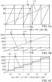
- FIGs. 4A to 4C explain the synchronization calculation, and a description will be given of a procedure for finalizing an absolute position from one phase difference signal correlated with an arbitrary position of the repetitive phase signal 9.
- FIG. 4A is a graph of the phase signal 9 shown by a solid line and the phase difference signal 11b shown by a broken line explained in FIGs. 3A-3C , where the abscissa axis denotes the length in the detection direction and the ordinate axis denotes the phase, and a range of degrees from 0° to 360° is shown. Since five waves of the phase signal 9 are shown and one wave of the phase difference signal 11b is shown, it is clear that the signal slopes are different by five times.
- FIG. 4C explains a calculation for determining the number of each wave of the phase signal 9 (code: referred to as a wave number hereinafter). Subtracting the phase signal 9 from the signal 11b' and adding 180° result in a stepped signal shown by reference numeral 12. While the phase signal 9 and the phase difference signal 11b are expressed by a clean straight line, the phase difference signal 11b is a difference signal between the phase signal 9 and the phase signal 10 illustrated in FIG. 3B and thus error components of both original signals are contained. The signal 11b' contains a larger error signal because it has been magnified by five times.
- the stepped signal 12 is not a clean straight line, for example, the first signal 12a is a signal including an error range by setting an average value to about 180° between 0° and 360°.
- N D INT 5 ⁇ ⁇ U ⁇ ⁇ D + 180 ⁇ 360
- N D becomes 2.
- INT() is a interger conversion (integerization) that rounds the decimal point.
- ⁇ 360 ⁇ N D + ⁇ D
- an accurate detection is available using the phase signal 9 as the original signal based on the phase difference signal 11b including the large error of the absolute position ⁇ by adding two prior phases 360 ⁇ 2 of the phase signal 9 to the phase ⁇ D of the phase signal 9 at the current position.
- FIGs. 5A to 5D explain detection units as a unit for detecting an absolute position.
- FIG. 5A illustrates one phase difference signal produced with the pitches Q 1 and Q 2
- FIG. 5B illustrates ten phase difference signals produced with pitches P 1 and P 2
- FIG. 5C illustrates seventy-five phase signals produced with the pitch Q 1
- FIG. 5D illustrates three hundred phase signals produced with the pitch P 1 .
- N X INT 10 ⁇ ⁇ W ⁇ ⁇ X + 180 ⁇ 360
- N Y INT 7.5 ⁇ 360 ⁇ N X + ⁇ X ⁇ ⁇ Y + 180 ⁇ 360
- N Z INT 4 ⁇ 360 ⁇ N Y + ⁇ Y ⁇ ⁇ Z + 180 ⁇ 360
- phase difference signal ⁇ X and the phase signals ⁇ Y and ⁇ Z as the lower signals (intermediate signal, lower signal and lowest signal) respectively are correlated with the phase difference signal ⁇ W of one wave as the uppermost signal illustrated in FIG. 5A .
- a portion of the length in the detection direction (relative movement amount) to which each wave number is attached in each of these signals is one detection unit.
- FIG. 6 illustrates a configuration of the position detection apparatus according to this embodiment. While the reflective scale 1 and the sensor 2 illustrated in FIG. 1 actually face each other, they are shown side by side in FIG. 6 .
- the range sandwiched between two equiphase lines in the reflective scale 1 is one detection unit (labelled as an absolute position detection unit in FIG. 6 ) described with reference to FIGs. 5A to 5D .
- the periodic patterns with the pitches P 1 , Q 1 , P 2 , and Q 2 are continuous on the right and left sides.
- the microcomputer 20 performs a variety of operations and determinations including the above synchronization calculation.
- the microcomputer 20 outputs the signal "a" from an I/O port 21 to switch the internal circuits of the light receiving ICs 4 and 5 in the time division manner. Thereby, the states in which the light receiving element arrays 4a and 4b read the first and second short periodic patterns 101a and 102a illustrated in FIG. 2 and the states in which the light receiving element arrays 4a and 4b read the first and second long period patterns 101b and 102b are alternately switched.
- the sensor 2 outputs two signals "b" having a 90° phase difference corresponding to the pitches P 1 and P 2 of the first and second short period patterns 101a and 102a or the pitch Q 1 and Q 2 of the first and second long period patterns 101b and 102b.
- An A/D converter 22 in the microcomputer 20 A/D-converts the signal b. Thereby, a signal as a digital signal is input to an processor 23 in the microcomputer 20.
- a light-shielding plate 31 is fixed onto a movable member, and moves integrally with the movable member.
- Photo-interrupters (PI _1 and PI_2) 30_1 and 30_2 that constitute a divider together with the light-shielding plate 31 switch the output signal between H and L when the light-shielding plate 31 enters and exits from the space between the light-emitting portion and the light-receiving portion.
- Output signals from the photo-interrupters 30_1 and 30_2 (referred to as division signals hereinafter) are input to the processor 23 through the I/O port 21 in the microcomputer 20.
- the processor 23 performs an arctangent transformation, a phase difference calculation, a synchronization calculation, and area determination processing using the input digital signal and division signal, and outputs the calculation and determination results to an absolute position calculator 24 in the microcomputer 20.
- the absolute position calculator 24 calculates the absolute position of the movable member using the input calculation and determination results.
- the processor 23 and the absolute position calculator 24 constitute a calculator.
- FIGs. 7A and 7B illustrate a specific configuration of the position detection apparatus according to this embodiment used for an interchangeable lens or a lens barrel for a camera.
- the lens barrel has a rotation ring 32 as the movable member rotatable by the user.
- the rotation ring 32 is rotatable around an optical axis in a predetermined rotation range relative to an unillustrated fixed barrel.
- the reflective scale 1 is fixed onto the inner circumference portion of the rotation ring 32 and extend in the circumferential direction (in the position detection direction).
- the sensor 2 facing the reflective scale 1 is fixed onto the outer circumference portion of an unillustrated fixed barrel.
- the position detection apparatus detects the rotational position (absolute position) of the rotation ring 32.
- the light-shielding plate 31 is integrated with the rotation ring 32.
- the light-shielding plate 31 rotates as the rotation ring 32 rotates, and moves in and out of the spaces between the light-emitting portions and the light-receiving portions of the photo-interrupters 30_1 and 30_2 fixed onto the fixed barrel.
- FIG. 8 is a developed view of the sensor 2 and the photo interrupters 30_1 and 30_2 fixed onto the fixed barrel and the reflective scale 1 and the light-shielding plate 31 integrally provided on the rotating ring 32 in the position detection direction in the configuration illustrated in FIGs. 7A and 7B .
- the rotational positions 1 and 4 of the rotation ring 32 indicate both end positions of the absolute position detection range.
- the photo-interrupters 30_1 and 30_2 as the detecting portions (detecting devices) output a division signal H in the light shielding state in which the light-shielding plate 31 enters the space between the light-emitting portion and the light-receiving portion, and a division signal L in the light transmission state in which the light-shielding plate 31 exits from the space between the light-emitting portion and the light-receiving portion.
- the absolute position detection range is divided into a plurality of (three in this embodiment) areas by the combination of the division signals from the photo interrupters 30_1 and 30_2. Each divided area will be referred to as a determination area in the following description.
- the photo-interrupters 30_1 and 30_2 as the detecting portions and the light-shielding plate 31 as the detected portion are arranged side by side in the rotation direction of the rotation ring 32 as the position detection direction.
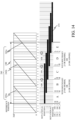
- FIG. 9 An upper side in FIG. 9 illustrates a phase difference signal ( ⁇ W ) 41 (41a to 41d) as the first signal illustrated in FIG. 5A in the absolute position detection range 40.
- a range in the position detection direction in which the phase of the phase difference signal 41 changes from 0° to 360° is one detection unit (first relative movement amount) of the phase difference signal 41.
- the absolute position detection range 40 has a length 2.3 times as long as the detection unit of the phase difference signal 41, and there are three boundaries among the detection units (first to fourth waves 41a to 41d) in the absolute position detection range 40. Assume that Nw is the wave number of the phase difference signal 41.
- the boundary between two adjacent waves in the phase difference signal ( ⁇ X ) as the second signal illustrated in FIG. 5B superimposed on the phase difference signal 41 is indicated by a vertical line.
- the numerals 0 to 9 attached between the boundaries or for each detection unit (second relative movement amount) of the phase difference signal ⁇ X are wave numbers Nx of the phase difference signal ⁇ X .
- FIG. 9 A lower side of FIG. 9 illustrates the position (illustrated in black) of the light-shielding plate 31 moving in the position detection direction with the reflective scale 1 and the division signals (H or L) from the photo-interrupters (PI_1 and PI_2) 30_1 and 30_2.
- This embodiment calculates the absolute position with the accuracy of the phase difference signal ⁇ X .
- the phase difference signal ⁇ X changes its phase from 0 to 360° for each wave.
- the absolute position detection range 40 is divided into three determination areas A, B, and C by the light-shielding plate 31 and the photo-interrupters 30_1 and 30_2 as described with reference to FIG. 8 .
- the length in the position detection direction of each determination area is shorter than "one detection unit" of the phase difference signal 41.
- the determination areas A, B, and C each include at most one boundary between two adjacent detection units (waves) in the phase difference signal 41 inside both ends thereof.
- the determination area A is an area from the rotational position 1 to the rotational position 2 illustrated in FIG. 8
- the determination area B is an area from the rotational position 2 to the rotational position 3.
- the determination area C is an area from the rotational position 3 to the rotational position 4.
- the microcomputer 20 that has started the absolute position calculation processing acquires position information from the sensor 2 in S051, and performs signal processing and synchronization calculation for the signal acquired in S052. Thereby, the phase difference signal ⁇ X and its wave number Nx are obtained.
- the microcomputer 20 acquires division signals from the photo-interrupters PI_1 and PI_2 in S053, and determines which determination area the division signal indicates in S054. As illustrated in FIG. 9 , when the division signals become L and L, the microcomputer 20 determines the determination area to be A and proceeds to S056, and otherwise proceeds to S055. In S055, if the division signals are H and L, the determination area is determined to be B, and the flow proceeds to S057. Otherwise (if the division signals are H and H), the determination area is determined to be C and the flow proceeds to S058.
- the microcomputer 20 specifies (determines) the wave number Nw of the phase difference signal ⁇ W using the wave number Nx of the phase difference signal ⁇ X . Then, the microcomputer 20 compares the wave number Nx with a predetermined value (predetermined code), and specifies the wave number Nw based on the result. More specifically, the microcomputer 20 proceeds to S059 and sets Nw to 0 if N X is 7 as a predetermined value or more or if the first wave 41a illustrated in FIG. 9 is indicated. If N X is 6 as a predetermined value or less or if the second wave 41b is indicated, the flow proceeds to S060 and Nw is set to 1.
- the microcomputer 20 specifies the wave number Nw of the phase difference signal ⁇ W using the wave number Nx of the phase difference signal ⁇ X .
- the microcomputer 20 proceeds to S061 and sets Nw to 1 if Nx is 5 as a predetermined value or more or if the second wave 41b is indicated. If N X is 4 or less or if the third wave 41c is indicated, the flow proceeds to S062 and Nw is set to 2.
- the microcomputer 20 specifies the wave number Nw of the phase difference signal ⁇ W using the wave number Nx of the phase difference signal ⁇ X .
- the microcomputer 20 proceeds to S063 and sets Nw to 2 if Nx is 3 as a predetermined value or more or if the third wave 41c is indicated. If N X is 2 or less or if the fourth wave 41d is indicated, the flow proceeds to S064 to set Nw to 3.
- the microcomputer 20 thus determining the wave number Nx of the current phase difference signal ⁇ X and the wave number Nw of the phase difference signal ( ⁇ W ) 41 calculates the present absolute position ⁇ according to the following expression (7) in S065, and ends this process.
- ⁇ 360 ° ⁇ 10 ⁇ N W + 360 ° ⁇ N X + ⁇ X ⁇ ⁇ X 0 ⁇ 30
- ⁇ X0 is a position where the reference position at the left end of the absolute position detection range 40 illustrated in FIG. 9 is represented by the phase difference signal ⁇ X . Since ⁇ X0 contains an error component due to the attachment error of the reflective scale 1 and the sensor 2 or the like, it is written in the memory area in the microcomputer 20 in the manufacturing process of the lens barrel. Regarding the end term ⁇ 30 in the expression (7), the absolute position is finalized by ⁇ X when the apparatus is powered on, and the subsequent positional change is used to adjust the range for the absolute position ⁇ by increasing and decreasing the absolute position ⁇ obtained from the value of ⁇ Z obtained from the pitch P 1 in FIG. 5D .
- the detection unit of the phase difference signal ⁇ X as the intermediate signal corresponds to 3 mm in detection length.
- the photo-interrupter PI_1 (30_1) is provided such that the signal is changed by the light-shielding plate 31 at the boundary between the wave with the wave number Nx of 5 and the wave with the wave number Nx of 6 in the phase difference signal ⁇ X .
- the wave number Nw of the phase difference signal ⁇ W as the uppermost signal is not erroneously determined, since a switch of the signal from the photo-interrupter PI_1 may be located within one of the waves with the wave numbers 5 and 6, it may be within ⁇ 3 mm from the boundary between these waves.
- the high relative positional accuracy is not required for the photo-interrupter PI_1 and the light-shielding plate 31.
- the position detection apparatus has the same configuration as that of the first embodiment ( FIG. 6 ), and detects the rotational position of the rotation ring 32 of the lens barrel described with reference to FIGs. 7A and 7B .
- FIG. 11 illustrates a phase signal 141 (141a to 141d) as the first signal in the absolute position detection range 140.
- the phase signal 141 is a signal made by converting the phase signal ⁇ Y with the pitch Q 1 obtained in FIGs. 5B and 5C into an absolute value with the wave number N Y .
- a range in the position detection direction in which the phase of the phase signal 141 changes from 0 to 27000° is one detection unit (first relative movement amount) of the phase signal 141.
- the absolute position detection range 140 has a length 2.3 times as long as the detection unit of the phase signal 141, and there are three boundaries among the detection units (first to fourth waves 141a to 141d) in the absolute position detection range 140.
- the wave number of the phase signal 141 is N F
- This embodiment calculates the absolute position with the accuracy of the phase signal ⁇ Z .
- This embodiment divides the absolute position detection range 140 into three determination areas A, B, and C similar to the first embodiment.
- the length in the position detection direction of each determination area is shorter than one detection unit of the phase difference signal 141.
- the determination areas A, B, and C each include only one boundary between two adjacent detection units (waves) in the phase difference signal 141 inside the both ends thereof.
- the microcomputer 20 executes this process according to a computer program.
- the microcomputer 20 that has started the absolute position calculation processing acquires the position information from the sensor 2 in S151, and performs signal processing and synchronization calculation for the signal acquired in S152. Thereby, the phase signal ⁇ z and its wave number Nz are obtained.
- the microcomputer 20 acquires division signals from the photo-interrupters PI_1 and PI_2 in S153, and determines which determination area the division signals indicate in S154. If the division signals are L and L, the microcomputer 20 determines the determination area to be A and the flow proceeds to S156, otherwise proceeds to S155. If the division signals are H and L in S155, the determination area is determined to be B and the flow proceeds to S157. Otherwise (if the division signals are H and H), the determination area is determined to be C and the flow proceeds to S158.
- the microcomputer 20 specifies (determines) the wave number N F of the phase signal 141 using the wave number Nz of the phase signal ⁇ Z . If N Z is 210 as the predetermined value (predetermined code) or more or if the first wave 141a illustrated in FIG. 11 is indicated, the microcomputer 20 proceeds to S159 and sets N F to 0. If N Z is equal to or less than 209 as the predetermined value or if the second wave 141b is indicated, the flow proceeds to S160 and N F is set to 1.
- the microcomputer 20 specifies the wave number N F of the phase signal 141 using the wave number Nz of the phase signal ⁇ Z . If N Z is 150 as the predetermined value or more or if the second wave 141b is indicated, the microcomputer 20 proceeds to S161 and sets N F to 1. If Nz is 149 as the predetermined value or less (if the third wave 141c is indicated), the flow proceeds to S162 to set N F to 2.
- the microcomputer 20 specifies the wave number N F of the phase signal 141 using the wave number Nz of the phase signal ⁇ Z . If N Z is 90 as the predetermined value or more or if the third wave 141c is indicated, the microcomputer 20 proceeds to S163 to set N F to 2. If Nz is 89 as the predetermined value or less or if the fourth wave 141d is indicated, the flow proceeds to S164 to set N F to 3.
- the microcomputer 20 having determined the wave number Nz of the current phase signal ⁇ z and the wave number N F of the phase difference signal 141 in this way calculates the present absolute position ⁇ according to the following expression (8) in S165 and ends this processing.
- ⁇ 27000 ° ⁇ 4 ⁇ N F + 360 ° ⁇ N Z + ⁇ Z ⁇ ⁇ Z 0
- ⁇ Z0 is a position where the reference position at the left end of the absolute position detection range 140 illustrated in FIG. 11 is represented by the phase signal ⁇ Z . Since ⁇ Z0 contains an error component due to the attachment error of the reflective scale 1 and the sensor 2, etc., it is written in the memory area in the microcomputer 20 in the manufacturing process of the lens barrel.
- the absolute position calculation accuracy is the accuracy of the phase difference signal ⁇ X in FIG. 5C similar to the first embodiment or the accuracy of the phase signal ⁇ z in FIG. 5D similar to the second embodiment may be determined based on the calculation load, the required accuracy of the absolute position of the lens barrel, whether the synchronization calculation accuracy can be guaranteed up to the phase signal ⁇ z, etc.
- the first and second embodiments divide the determination area using the light-shielding plate 31 provided on the rotation ring 32 holding the reflective scale 1 and the photo-interrupters 30_1 and 30_2 fixed onto the fixed barrel. On the other hand, this embodiment divides the determination area by another method.
- the absolute position calculation processing is the same as that of each of the first embodiment or the second embodiment.
- FIGs. 13A and 13B illustrate a specific configuration when the position detection apparatus according to this embodiment is used for a lens barrel.
- This figure illustrates a known lens moving mechanism mounted on an interchangeable lens barrel or the like.
- Reference numeral 210 denotes a linear movement guide barrel having three linear grooves 210a
- reference numeral 211 denotes a cam barrel having three cam grooves 211a.
- a lens barrel 212 and three cam follower pins 213 are fixed onto the lens barrel 212 at equal angles in the circumferential direction.
- the three cam follower pins 213 are held between the three linear grooves 210a and the three cam grooves 211a to support the lens, and as the cam barrel 211 rotates, the lens barrel moves forward and backward.
- An area detection lift portion 231 has an end surface 231b provided at a rear end portion of the cam barrel 211, which includes a first end surface 231a and a second end surface 231b formed in front of the first end surface 231a by one stage and formed in a circumferential direction range different from the first end surface 231a.
- Micro switches 230_1, 230_2, and 230_3 are held by an unillustrated fixed barrel at a position opposite to the area detection lift portion 231. Each micro switch outputs an L signal (division signal) where its switch pin faces the second end surface 231b, and an H division signal as the switch pin is squeezed by the first end surface 231a.
- the micro switches 230_1, 230_2, and 230_3 as at least one detecting portion and the area detection lift unit 231 as the detected portion are arranged side by side in the rotation direction of the cam barrel 211, which is the position detection direction.
- the upper side in FIG. 14 illustrates the phase difference signal ( ⁇ W ) 241 (241a to 241c) illustrated in FIG. 5A in the absolute position detection range 240.
- a range in the position detection direction in which the phase of the phase difference signal 241 changes from 0 to 360° is one detection unit of the phase difference signal 241.
- the absolute position detection range 240 has a length 2.3 times as long as the detection unit of the phase difference signal 241, and there are two boundaries between the detection units (first to third waves 241a to 241c) in the absolute position detection range 240.
- Nw is the wave number of the phase difference signal 241.
- the wave number of the second wave 241b 1
- a vertical line shows a boundary between two adjacent waves in the phase difference signal ⁇ X illustrated in FIG. 5B superimposed on the phase difference signal 241.
- the numerals 0 to 9 attached between the boundaries or for each detection unit of the phase difference signal ⁇ X are the wave numbers Nx of the phase difference signal ⁇ X .
- the lower side in FIG. 14 illustrates the position (illustrated in black) of the area detection lift portion 231 moving in the position detection direction with the reflective scale 1 and the division signals (H or L) from the micro switches (SW_1, SW_2, SW_3) 230_1, 230_2, and 230_3.
- This embodiment calculates the absolute position with the accuracy of the phase difference signal ⁇ X .
- the phase difference signal ⁇ X changes its phase from 0 to 360° for each wave.
- the absolute position detection range 240 is divided into five determination areas A, B, C, D, and E by the area detection lift portion 231 and the micro switches 230_1, 230_2, and 230_3. Each determination area in the position detection direction is shorter than one detection unit of the phase difference signal 241.
- the determination areas B and D each include only one boundary between two adjacent detection units (waves) in the phase difference signal 241 inside the both ends thereof.
- the rotational positions 1 and 6 of the cam barrel 211 indicate both end positions of the absolute position detection range 240.
- the division signals output from the micro switches 230_1, 230_2, and 230_3 are H, H, and L, respectively, from the rotational position 1 to the rotational position 2 (in the determination area A). From the rotational position 2 to the rotational position 3 (in the determination area B), the division signal from the micro switch 230_3 becomes L to H, and the division signals from the micro switches 230_1, 230_2, and 230_3 become H, H, and H, respectively.
- the division signal from the micro switch 230_1 changes from H to L, and the division signals from the micro switches 230_1, 230_2, and 230_3 become L, H, and H, respectively.
- the division signal from the micro switch 230_2 changes from H to L, and the division signals from the micro switches 230_1, 230_2, and 230_3 become L, L, and H, respectively.
- the division signal from the micro switch 230_3 changes from H to L, and the division signals from the micro switches 230_1, 230_2, and 230_3 become L, L, and L, respectively.
- the microcomputer 20 executes this processing according to a computer program.
- the microcomputer 20 that has started the absolute position calculation processing acquires the position information from the sensor in S251, and performs signal processing and synchronization calculation for the signal acquired in S252. Thereby, the phase difference signal ⁇ X and its wave number Nx are obtained.
- the microcomputer 20 acquires the division signals from the micro switches 230_1, 230_2, and 230_3 in S253, and determines which determination area the division signals indicate in S254. If the division signals are H, H, and L, the microcomputer 20 determines that the determination area is A and proceeds to S260, otherwise proceeds to S255. The microcomputer 20 sets Nw to 0 in S260.
- the microcomputer 20 proceeds to S258, otherwise proceeds to S256. If the division signals are L, H, and H in S256, the microcomputer 20 determines the determination area to be C and proceeds to S263 to set Nw to 1, otherwise proceeds to S257. If the division signals are L, L, and H in S257, the microcomputer 20 proceeds to S259. Otherwise, the microcomputer 20 determines the determination area to be E and proceeds to S266 to set Nw to 2.
- the microcomputer 20 specifies (determines) the wave number Nw of the phase difference signal ⁇ W using the wave number Nx of the phase difference signal ⁇ X . If N X is 5 as the predetermined value (predetermined code) or more or if the first wave 241a illustrated in FIG. 11 is indicated, the microcomputer 20 proceeds to S261 and sets Nw to 0. If N X is 4 as the predetermined value or less or if the second wave 241b is indicated, the flow proceeds to S262 to set Nw to 1.
- the microcomputer 20 specifies the wave number Nw of the phase difference signal ⁇ W using the wave number Nx of the phase difference signal ⁇ X .
- the microcomputer 20 proceeds to S264 and sets Nw to 1 if Nx is 5 as the predetermined value or more or if the second wave 241b is indicated. If N X is 4 or less or if the third wave 241c is indicated, the flow proceeds to S265 to set Nw 2.
- the microcomputer 20 having thus determined the wave number Nx of the current phase difference signal ⁇ X and the wave number Nw of the phase difference signal ( ⁇ W ) 241 calculates the current absolute position ⁇ through the expression (7) described in S267 in the first embodiment, and ends this flow. Similar to the first embodiment, ⁇ X0 in the expression (7) is a position where the reference position at the left end of the absolute position detection range 240 illustrated in FIG. 14 is represented by the phase difference signal ⁇ X .
- This embodiment increases the number of divisions of the detection range of the same length from 3 to 5 as compared with the first embodiment, and sets the boundaries on both sides of the determination area are set to wave numbers Nx to 7 and 2 with respect to the wave number Nx of 5 as the predetermined value used to determine the second and fourth areas including the boundary of the upper signal. Since there is room at the boundary position wider than that of the first embodiment, the setting accuracy can be mitigated. As illustrated in FIGs. 7A and 7B , the first embodiment determines the area by the light-shielding plate 31 and the photo-interrupters 30_1 and 30_2 integrated with the rotating ring 32 onto which the reflective scale 1 is fixed.
- this embodiment mitigates the area determination accuracy, the erroneous detection can be sufficiently prevented even if the area is divided at a portion that is not a member to which the reflective scale is attached.
- FIGs. 16A and 16B illustrate a specific configuration where the position detection apparatus according to this embodiment is used for an interchangeable lens or a lens barrel for a camera.
- the lens barrel includes a lens holding frame 312 configured to hold a lens 300, a guide bar 310 configured to guide the lens holding frame 312 in the optical axis direction, and a rotation preventive bar 311 configured to prevent the lens holding frame 312 from rotating around the guide bar 310.
- a reflective scale 301 is fixed onto the lens holding frame 312 so as to extend in the optical axis direction.
- a sensor 302 is fixed at a position facing the reflective scale 301 in an unillustrated fixed barrel.
- the reflective scale 301 and the sensor 302 are configured similar to the first embodiment.
- a photo-interrupter (PI) 330 is fixed onto the fixed barrel, and a light-shielding plate 331 is integrated with the lens holding frame 312.
- the light-shielding plate 331 is not inserted into a space between the light-emitting portion and the light-receiving portion of the photo-interrupter 330 and is in a light transmitting state.
- FIG. 16B when the lens holding frame 312 moves in the arrow direction along the optical axis direction, the light-shielding plate 331 enters the space between the light-emitting portion and the light-receiving portion of the photo-interrupter 330 and is in the light shielding state.
- FIG. 17 An upper side in FIG. 17 illustrates a phase difference signal ( ⁇ W ) 341 (341a to 341c) illustrated in FIG. 5A in the absolute position detection range 340.
- a range in the position detection direction in which the phase of the phase difference signal 341 changes from 0 to 360° is one detection unit of the phase difference signal 341.
- the absolute position detection range 340 has a length 1.5 times as long as the detection unit in the phase difference signal 341, and there are two boundaries between the detection units (first to third waves 341a to 341c) in the absolute position detection range 340.
- Three detection units of the phase difference signal 341 are included in the absolute position detection range 340.
- Nw the wave number of the phase difference signal 341.
- a vertical line shows a boundary between two adjacent waves in the phase difference signal ⁇ X as the intermediate signal illustrated in FIG. 5B superimposed on the phase difference signal 341.
- the numerals 0 to 9 attached between the boundaries or for each detection unit of the phase difference signal ⁇ X are the wave numbers Nx of the phase difference signal ⁇ X .
- the lower side in FIG. 17 illustrates the position (illustrated in black) of the light-shielding plate 331 moving in the position detection direction with the reflective scale 1 and the division signal (H or L) from the photo interrupter 330.
- This embodiment calculates the absolute position with the accuracy of the phase difference signal ⁇ X .
- the phase difference signal ⁇ X changes its phase from 0 to 360° for each wave.
- the absolute position detection range 340 is divided into two determination areas A and B by the light-shielding plate 331 and the photo interrupter 330. Each determination area in the position detection direction is shorter than one detection unit of the phase difference signal 341.
- the determination areas A and B each include only one boundary between two adjacent detection units (waves) in the phase difference signal 341 inside both ends thereof.
- the microcomputer 20 executes this processing according to a computer program.
- the microcomputer 20 that has started the absolute position calculation processing acquires the position information from the sensor 302 in S451, and performs signal processing and synchronization calculation for the signal acquired in S452. Thereby, the phase difference signal ⁇ X and its wave number Nx are obtained.
- the microcomputer 20 obtains a division signal from the photo-interrupter 330 in S453, and determines which determination area the division signal indicates in next S454. As illustrated in FIG. 17 , when the division signal is L, the microcomputer 20 determines the determination area to be A and proceeds to S455, otherwise determines the determination area to be B and proceeds to S456.
- the microcomputer 20 specifies (discriminates) the wave number Nw of the phase difference signal ⁇ W using the wave number Nx of the phase difference signal ⁇ X . If N X is 7 as the predetermined value (predetermined code) or more or if the first wave 341a illustrated in FIG. 17 is indicated, the microcomputer 20 proceeds to S457 and sets Nw to 0. If Nx is 6 as the predetermined value or less or if the second wave 341b is indicated, the flow proceeds to S458 to set Nw to 1.
- the microcomputer 20 specifies the wave number Nw of the phase difference signal ⁇ W using the wave number Nx of the phase difference signal ⁇ X . If the Nx is 5 as the predetermined value or more or if the second wave 341b is indicated, the microcomputer 20 proceeds to S459 and sets Nw to 1. If N X is 4 or less or if the third wave 341c is indicated, the flow proceeds to S460 to set Nw to 2.
- the microcomputer 20 having thus determined the wave number Nx of the current phase difference signal ⁇ X and the wave number Nw of the phase difference signal ( ⁇ W ) 341 calculates the current absolute position ⁇ through the expression (7) described in S461 in the first embodiment, and ends this processing. Similar to the first embodiment, ⁇ X0 in the expression (7) is a position where the reference position at the left end of the absolute position detection range 340 illustrated in FIG. 17 is represented by the phase difference signal ⁇ X .
- the first to fourth embodiments described above can detect the absolute position of the movable member with high accuracy without limiting the movement amount of the movable member (32, 211, 312).
- the first to fourth embodiments fix the scale onto the movable member and the sensor onto the fixed member, but the scale may be fixed onto the fixed member and the sensor may be fixed onto the movable member.
- the first to fourth embodiments describe use of the reflective scale as the scale, but may use a transmission scale.
- the divider is not limited to that exemplified in the first to fourth embodiments, and any configuration may be used as long as it can generate a division signal for dividing the absolute position detection range into a plurality of determination areas.
- the first to fourth embodiments describe the number (wave number) as a code added to each detection unit (wave) of the second signal, but the code may not be the number and may be different for each detection unit.
- first to fourth embodiments have described the lens barrel used for an optical apparatus such as an interchangeable lens and a camera, other embodiments of the present invention are applicable to a variety of apparatuses other than the optical apparatus.
- Each embodiment can detect the absolute position of the movable member with high accuracy without limiting the movement amount of the movable member.
- Embodiment(s) of the present invention can also be realized by a computer of a system or apparatus that reads out and executes computer executable instructions (e.g., one or more programs) recorded on a storage medium (which may also be referred to more fully as a 'non-transitory computer-readable storage medium') to perform the functions of one or more of the above-described embodiment(s) and/or that includes one or more circuits (e.g., application specific integrated circuit (ASIC)) for performing the functions of one or more of the above-described embodiment(s), and by a method performed by the computer of the system or apparatus by, for example, reading out and executing the computer executable instructions from the storage medium to perform the functions of one or more of the above-described embodiment(s) and/or controlling the one or more circuits to perform the functions of one or more of the above-described embodiment(s).
- computer executable instructions e.g., one or more programs
- a storage medium which may also be referred to more fully as
- the computer may comprise one or more processors (e.g., central processing unit (CPU), micro processing unit (MPU)) and may include a network of separate computers or separate processors to read out and execute the computer executable instructions.
- the computer executable instructions may be provided to the computer, for example, from a network or the storage medium.
- the storage medium may include, for example, one or more of a hard disk, a random-access memory (RAM), a read only memory (ROM), a storage of distributed computing systems, an optical disk (such as a compact disc (CD), digital versatile disc (DVD), or Blu-ray Disc (BD) TM ), a flash memory device, a memory card, and the like.
- An absolute position detection apparatus includes a calculator (23, 24) configured to generate, based on a detection signal, a first signal, and a second signal.
- a relative movement range of a scale (1) and a sensor (2) includes a boundary between adjacent detection units in the first signal such that at least one of the boundary is included in each of a plurality of areas in the relative movement range.
- the calculator is configured to specify a detection unit, to be used to calculate the absolute position, in the first signal based on a code of each detection unit of the second signal in an area that includes the boundary of the plurality of areas.
Landscapes
- Physics & Mathematics (AREA)
- General Physics & Mathematics (AREA)
- Transmission And Conversion Of Sensor Element Output (AREA)
- Optical Transform (AREA)
Claims (7)
- Absolutpositionserfassungsvorrichtung, mit:einer Skala (1) mit einer Hauptbahn (1a) und einer Nebenbahn (1b), wobei jede zwei Arten von periodischen Mustern mit unterschiedlichen Abständen (P1, P2, Q1, Q2) aufweist,einem Sensor (2), der dazu eingerichtet ist, um zwei Sinuswellenerfassungssignale mit einer 90°-Phasendifferenz, wobei jedes Erfassungssignal jeweils den Arten von periodischen Mustern der Hauptbahn (1a) und der Nebenbahn (1b) entspricht, gemäß einer Relativbewegung zwischen der Skala und dem Sensor auszugeben, undeiner Recheneinrichtung (23, 24), die dazu eingerichtet ist, um basierend auf Phaseninformation, die der Relativbewegung entspricht und durch Arkustangens-Transformation der zwei Sinuswellenerfassungssignale mit der 90°-Phasendifferenz erlangt ist, ein erstes Signal, das eine Erfassungseinheit auf ein erstes Relativbewegungsausmaß zwischen der Skala und dem Sensor eingestellt aufweist, und ein zweites Signal, das eine Erfassungseinheit auf ein zweites Relativbewegungsausmaß kleiner als das erste Relativbewegungsausmaß zwischen der Skala und dem Sensor eingestellt aufweist, zu erzeugen, wobei das erste Signal das erste Relativbewegungsausmaß entsprechend einer Vielzahl aufeinanderfolgender das zweite Relativbewegungsausmaß angebender zweiter Signale angibt, um als einen Code entsprechend jedem der Vielzahl von zweiten Signalen eine Beziehung zwischen dem ersten Signal und der Vielzahl von zweiten Signalen durch Vergleich des ersten Signals und der Vielzahl von zweiten Signalen zu bestimmen, und um basierend auf den ersten und zweiten Signalen eine Absolutposition in einer Relativbewegungsrichtung der Skala und des Sensors zu erhalten,dadurch gekennzeichnet, dasseine Relativbewegungsspanne der Skala und des Sensors eine Grenze umfasst, die ein Wiederholungsteil benachbarter Erfassungseinheiten in dem ersten Signal ist,die Absolutpositionserfassungsvorrichtung ferner einen ersten Fotounterbrecher (30_1) und einen zweiten Fotounterbrecher (30_2) aufweist, die jeweils dazu eingerichtet sind, um ein Signal für eine Bestimmung einer Vielzahl von in der Relativbewegungsspanne eingestellten Bereichen auszugeben,der erste Fotounterbrecher und der zweite Fotounterbrecher derart vorgesehen sind, dass höchstens eine der jeweiligen Grenzen des ersten Signals innerhalb beider Enden jeder der Vielzahl von Bereichen enthalten ist,in jeder der Vielzahl von Bereichen der Code jeder Erfassungseinheit des zweiten Signals voneinander verschieden ist, und dadurch, dassdie Recheneinrichtung dazu eingerichtet ist, um eine Erfassungseinheit des zu einer Berechnung der Absolutposition zu verwendenden ersten Signals basierend auf dem Code jeder Erfassungseinheit des zweiten Signals in einem Bereich, aus der Vielzahl von Bereichen, der die Grenze des ersten Signals innerhalb beider Enden aufweist, zu spezifizieren.
- Absolutpositionserfassungsvorrichtung nach Anspruch 1, wobei jeder der Vielzahl von Bereichen kürzer als die Erfassungseinheit des ersten Signals in einer Richtung der Relativbewegung ist.
- Absolutpositionserfassungsvorrichtung nach Anspruch 1 oder 2, wobei die Recheneinrichtung dazu eingerichtet ist, um die Erfassungseinheit in dem ersten Signal basierend auf einem Vergleich des Codes mit einem vorbestimmten Code zu spezifizieren.
- Absolutpositionserfassungsvorrichtung nach einem der Ansprüche 1 bis 3, ferner mit zumindest einem Erfassungsgerät, das dazu eingerichtet ist, um ein Teilungssignal auszugeben, um die Relativbewegungsspanne in die Vielzahl von Bereichen zu teilen.
- Vorrichtung, mit:die Absolutpositionserfassungsvorrichtung nach einem der Ansprüche 1 bis 4, undeinem beweglichen Element (32, 211, 312), dessen Absolutposition durch die Absolutpositionserfassungsvorrichtung erfasst ist.
- Absolutpositionserfassungsverfahren unter Verwendung einer Skala (1) mit einer Hauptbahn (1a) und einer Nebenbahn (1b), wobei jede zwei Arten von periodischen Mustern mit unterschiedlichen Abständen (P1, P2, Q1, Q2) aufweist, und eines Sensors (2), der dazu eingerichtet ist, um zwei Sinuswellenerfassungssignale mit einer 90°-Phasendifferenz, wobei jedes Erfassungssignal jeder der Vielzahl von Arten von periodischen Mustern entspricht, gemäß einer Relativbewegung zwischen der Skala und dem Sensor auszugeben, wobei das Absolutpositionserfassungsverfahren die folgenden Schritte aufweist:ein Erzeugen, basierend auf Phaseninformation, die der Relativbewegung entspricht und durch Arkustangens-Transformation der zwei Sinuswellenerfassungssignale mit der 90°-Phasendifferenz erlangt wird, eines ersten Signals, das eine Erfassungseinheit auf ein erstes Relativbewegungsausmaß zwischen der Skala und dem Sensor eingestellt aufweist, und eines zweiten Signals, das eine Erfassungseinheit auf ein zweites Relativbewegungsausmaß kleiner als das erste Relativbewegungsausmaß zwischen der Skala und dem Sensor eingestellt aufweist, wobei das erste Signal das erste Relativbewegungsausmaß entsprechend einer Vielzahl aufeinanderfolgender das zweite Relativbewegungsausmaß angebender zweiter Signale angibt,ein Bestimmen, als einen Code entsprechend jedem der Vielzahl von zweiten Signalen, einer Beziehung zwischen dem ersten Signal und der Vielzahl von zweiten Signalen durch Vergleichen des ersten Signals und der Vielzahl von zweiten Signalen, undein Erhalten, basierend auf den ersten und zweiten Signalen, einer Absolutposition in einer Relativbewegungsrichtung der Skala und des Sensors,dadurch gekennzeichnet, dasseine Relativbewegungsspanne der Skala und des Sensors eine Grenze umfasst, die ein Wiederholungsteil benachbarter Erfassungseinheiten in dem ersten Signal ist,das Positionserfassungsverfahren ferner den Schritt eines Ausgebens eines Signals für ein Bestimmen einer Vielzahl von in der Relativbewegungsspanne eingestellten Bereichen derart, dass höchstens eine der jeweiligen Grenzen des ersten Signals innerhalb beider Enden jeder der Vielzahl von Bereichen enthalten ist,in jeder der Vielzahl von Bereichen der Code jeder Erfassungseinheit des zweiten Signals voneinander verschieden ist, und dadurch, dassder Schritt eines Erhaltens eine Erfassungseinheit des zu einer Berechnung der Absolutposition zu verwendenden ersten Signals basierend auf dem Code jeder Erfassungseinheit des zweiten Signals in einem Bereich, aus der Vielzahl von Bereichen, der die Grenze des ersten Signals innerhalb beider Enden aufweist, spezifiziert.
- Computerprogramm, mit Anweisungen die, wenn das Programm durch einen Computer ausgeführt wird, den Computer dazu bringen, das Absolutpositionserfassungsverfahren nach Anspruch 6 durchzuführen.
Applications Claiming Priority (1)
| Application Number | Priority Date | Filing Date | Title |
|---|---|---|---|
| JP2018157893A JP7118809B2 (ja) | 2018-08-27 | 2018-08-27 | 位置検出装置およびこれを備えた装置、位置検出方法およびコンピュータプログラム |
Publications (2)
| Publication Number | Publication Date |
|---|---|
| EP3617661A1 EP3617661A1 (de) | 2020-03-04 |
| EP3617661B1 true EP3617661B1 (de) | 2023-07-12 |
Family
ID=67766084
Family Applications (1)
| Application Number | Title | Priority Date | Filing Date |
|---|---|---|---|
| EP19193598.0A Active EP3617661B1 (de) | 2018-08-27 | 2019-08-26 | Absolutpositiondetektionsvorrichtung und -verfahren und computerprogramm |
Country Status (4)
| Country | Link |
|---|---|
| US (1) | US11193800B2 (de) |
| EP (1) | EP3617661B1 (de) |
| JP (1) | JP7118809B2 (de) |
| CN (1) | CN110864713B (de) |
Family Cites Families (29)
| Publication number | Priority date | Publication date | Assignee | Title |
|---|---|---|---|---|
| GB1096022A (en) * | 1963-06-21 | 1967-12-20 | Cooke Conrad Reginald | Improvements in or relating to apparatus for detecting and indicating the extent of relative movement |
| JPH04232814A (ja) * | 1990-12-28 | 1992-08-21 | Citizen Watch Co Ltd | 高分解能絶対値エンコ−ダ |
| JPH04295719A (ja) | 1991-03-25 | 1992-10-20 | Nikon Corp | アブソリュ−ト・エンコ−ダ |
| JP3021805B2 (ja) * | 1991-07-22 | 2000-03-15 | ソニー・プレシジョン・テクノロジー株式会社 | 測尺装置 |
| CN1151361C (zh) * | 1996-05-20 | 2004-05-26 | 松下电器产业株式会社 | 光学编码器及位置检测方法 |
| DE19642200A1 (de) * | 1996-10-12 | 1998-04-16 | Heidenhain Gmbh Dr Johannes | Kontrollvorrichtung und Verfahren zur Prüfung von positionsabhängigen Abtastsignalen |
| US5841274A (en) * | 1997-01-29 | 1998-11-24 | Mitutoyo Corporation | Induced current absolute position transducer using a code-track-type scale and read head |
| JP3610905B2 (ja) * | 1998-11-09 | 2005-01-19 | 三菱電機株式会社 | 位置検出装置 |
| JP4138138B2 (ja) | 1999-03-05 | 2008-08-20 | 株式会社ミツトヨ | 絶対変位測定装置 |
| JP3743426B2 (ja) * | 2002-02-13 | 2006-02-08 | オムロン株式会社 | 光学式エンコーダ |
| JP3977126B2 (ja) * | 2002-04-12 | 2007-09-19 | キヤノン株式会社 | 変位情報検出装置 |
| TWI234935B (en) * | 2004-02-26 | 2005-06-21 | Southern Taiwan University Of | Encoding method of high-resolution magnet inductive encoder |
| JP4947774B2 (ja) * | 2006-08-18 | 2012-06-06 | 富士フイルム株式会社 | 光波干渉測定装置および光波干渉測定方法 |
| JP4960133B2 (ja) * | 2007-04-11 | 2012-06-27 | 株式会社ミツトヨ | 絶対位置測長型エンコーダ |
| JP2009068978A (ja) | 2007-09-13 | 2009-04-02 | Iai:Kk | アブソリュート型リニアエンコーダとアクチュエータ |
| CN101532852B (zh) * | 2008-03-14 | 2010-12-15 | 上海精浦机电有限公司 | 智能型增量式或者绝对值编码器的线路板及其工作方法 |
| JP5560847B2 (ja) | 2010-03-31 | 2014-07-30 | 株式会社ニコン | エンコーダ |
| US8309906B2 (en) * | 2010-06-10 | 2012-11-13 | Mitutoyo Corporation | Absolute optical encoder with long range intensity modulation on scale |
| JP5982161B2 (ja) | 2012-04-11 | 2016-08-31 | 株式会社ミツトヨ | エンコーダ |
| JP6032936B2 (ja) | 2012-05-07 | 2016-11-30 | キヤノン株式会社 | バーニア方式位置検出エンコーダ用スケール、バーニア方式位置検出エンコーダおよびこれを備えた装置 |
| JP6000759B2 (ja) | 2012-08-31 | 2016-10-05 | キヤノン株式会社 | スケール、エンコーダ、レンズ装置、および、撮像システム |
| JP6253320B2 (ja) | 2013-09-13 | 2017-12-27 | キヤノン株式会社 | エンコーダおよびこれを用いた装置 |
| JP6313571B2 (ja) * | 2013-11-12 | 2018-04-18 | キヤノン株式会社 | 位置検出装置及びそれを有するレンズ装置及び撮影装置 |
| CN104596556A (zh) * | 2015-01-08 | 2015-05-06 | 佛山轻子精密测控技术有限公司 | 一种新型编码器及其测量方法 |
| JP6555903B2 (ja) | 2015-03-03 | 2019-08-07 | キヤノン株式会社 | 位置検出装置およびこれを用いた装置 |
| US10113888B2 (en) | 2015-03-03 | 2018-10-30 | Canon Kabushiki Kaisha | Position detection apparatus, apparatus including the same and position detection method |
| JP6739911B2 (ja) | 2015-09-04 | 2020-08-12 | キヤノン株式会社 | 位置検出装置、レンズ装置、および撮像装置 |
| JP2018036090A (ja) | 2016-08-30 | 2018-03-08 | キヤノンプレシジョン株式会社 | エンコーダおよびこれを備えた装置 |
| JP6769799B2 (ja) * | 2016-09-21 | 2020-10-14 | 日本電産サンキョー株式会社 | ロータリエンコーダ、およびロータリエンコーダの絶対角度位置検出方法 |
-
2018
- 2018-08-27 JP JP2018157893A patent/JP7118809B2/ja active Active
-
2019
- 2019-08-09 US US16/536,729 patent/US11193800B2/en active Active
- 2019-08-22 CN CN201910781002.1A patent/CN110864713B/zh active Active
- 2019-08-26 EP EP19193598.0A patent/EP3617661B1/de active Active
Also Published As
| Publication number | Publication date |
|---|---|
| JP2020034273A (ja) | 2020-03-05 |
| US11193800B2 (en) | 2021-12-07 |
| CN110864713A (zh) | 2020-03-06 |
| JP7118809B2 (ja) | 2022-08-16 |
| EP3617661A1 (de) | 2020-03-04 |
| CN110864713B (zh) | 2023-01-10 |
| US20200064164A1 (en) | 2020-02-27 |
Similar Documents
| Publication | Publication Date | Title |
|---|---|---|
| EP2894437B1 (de) | Codierer, Vorrichtung mit Codierer, Codiererberechnungsverfahren, Codiererberechnungsprogramm und Speichermedium zur Speicherung des Codiererberechnungsprogramms | |
| EP2778623B1 (de) | Positionsmess-, Linsenvorrichtung, Bildaufnahmesystem und Maschinenwerkzeugapparat | |
| EP2343510B1 (de) | Drehcodierer | |
| EP3035003B1 (de) | Positionsdetektionsvorrichtung, linsenvorrichtung, bildaufnahmesystem, werkzeugmaschinenvorrichtung, positionsdetektionsverfahren, programm und speichermedium | |
| EP2662668B1 (de) | Skala, Vernierkodierer und Vorrichtung damit | |
| CN109916312A (zh) | 光栅尺读数头、光栅尺接头及光栅尺位移传感器 | |
| US20120283986A1 (en) | System and Method for Measuring Positions | |
| US20150271466A1 (en) | Measuring device, measuring method, and computer program product | |
| JP6103927B2 (ja) | 位置検出装置、駆動制御装置及びレンズ装置 | |
| EP2937672A1 (de) | Absolutcodierer, verarbeitungsverfahren, programm, ansteuerungsvorrichtung und industriemaschine | |
| US9103699B2 (en) | Encoder and apparatus using the same | |
| EP3617661B1 (de) | Absolutpositiondetektionsvorrichtung und -verfahren und computerprogramm | |
| EP2963393A1 (de) | Absolutcodierer | |
| EP3290872B1 (de) | Codierer und vorrichtung damit | |
| JP2013246054A (ja) | モータ制御装置、モータ制御装置の制御方法 | |
| EP2803948B1 (de) | Referenzsignalerzeugungsvorrichtung und Referenzsignalerzeugungssystem | |
| EP2733469A2 (de) | Messvorrichtung, Messverfahren, und Absolutpositionsgeber | |
| EP2962071A1 (de) | Absolutcodierer | |
| JP2014224745A (ja) | 原点信号発生装置及び原点信号発生システム | |
| JP2017044500A (ja) | アブソリュートエンコーダ、駆動装置および産業装置 | |
| EP1526361A1 (de) | Analoger Positionskodierer | |
| JPH0251020A (ja) | 位置検出装置 | |
| JPH06294611A (ja) | 光学式変位計 | |
| JP2005292078A (ja) | インクリメンタル型変位測定装置 | |
| JPH11232030A (ja) | 入力装置、ポインティングデバイス |
Legal Events
| Date | Code | Title | Description |
|---|---|---|---|
| PUAI | Public reference made under article 153(3) epc to a published international application that has entered the european phase |
Free format text: ORIGINAL CODE: 0009012 |
|
| STAA | Information on the status of an ep patent application or granted ep patent |
Free format text: STATUS: THE APPLICATION HAS BEEN PUBLISHED |
|
| AK | Designated contracting states |
Kind code of ref document: A1 Designated state(s): AL AT BE BG CH CY CZ DE DK EE ES FI FR GB GR HR HU IE IS IT LI LT LU LV MC MK MT NL NO PL PT RO RS SE SI SK SM TR |
|
| AX | Request for extension of the european patent |
Extension state: BA ME |
|
| STAA | Information on the status of an ep patent application or granted ep patent |
Free format text: STATUS: REQUEST FOR EXAMINATION WAS MADE |
|
| 17P | Request for examination filed |
Effective date: 20200904 |
|
| RBV | Designated contracting states (corrected) |
Designated state(s): AL AT BE BG CH CY CZ DE DK EE ES FI FR GB GR HR HU IE IS IT LI LT LU LV MC MK MT NL NO PL PT RO RS SE SI SK SM TR |
|
| STAA | Information on the status of an ep patent application or granted ep patent |
Free format text: STATUS: EXAMINATION IS IN PROGRESS |
|
| 17Q | First examination report despatched |
Effective date: 20210204 |
|
| GRAP | Despatch of communication of intention to grant a patent |
Free format text: ORIGINAL CODE: EPIDOSNIGR1 |
|
| STAA | Information on the status of an ep patent application or granted ep patent |
Free format text: STATUS: GRANT OF PATENT IS INTENDED |
|
| INTG | Intention to grant announced |
Effective date: 20220223 |
|
| GRAJ | Information related to disapproval of communication of intention to grant by the applicant or resumption of examination proceedings by the epo deleted |
Free format text: ORIGINAL CODE: EPIDOSDIGR1 |
|
| STAA | Information on the status of an ep patent application or granted ep patent |
Free format text: STATUS: EXAMINATION IS IN PROGRESS |
|
| INTC | Intention to grant announced (deleted) | ||
| GRAP | Despatch of communication of intention to grant a patent |
Free format text: ORIGINAL CODE: EPIDOSNIGR1 |
|
| STAA | Information on the status of an ep patent application or granted ep patent |
Free format text: STATUS: GRANT OF PATENT IS INTENDED |
|
| INTG | Intention to grant announced |
Effective date: 20230120 |
|
| GRAS | Grant fee paid |
Free format text: ORIGINAL CODE: EPIDOSNIGR3 |
|
| GRAA | (expected) grant |
Free format text: ORIGINAL CODE: 0009210 |
|
| STAA | Information on the status of an ep patent application or granted ep patent |
Free format text: STATUS: THE PATENT HAS BEEN GRANTED |
|
| AK | Designated contracting states |
Kind code of ref document: B1 Designated state(s): AL AT BE BG CH CY CZ DE DK EE ES FI FR GB GR HR HU IE IS IT LI LT LU LV MC MK MT NL NO PL PT RO RS SE SI SK SM TR |
|
| REG | Reference to a national code |
Ref country code: CH Ref legal event code: EP |
|
| REG | Reference to a national code |
Ref country code: IE Ref legal event code: FG4D |
|
| REG | Reference to a national code |
Ref country code: DE Ref legal event code: R096 Ref document number: 602019032439 Country of ref document: DE |
|
| REG | Reference to a national code |
Ref country code: LT Ref legal event code: MG9D |
|
| REG | Reference to a national code |
Ref country code: NL Ref legal event code: MP Effective date: 20230712 |
|
| REG | Reference to a national code |
Ref country code: AT Ref legal event code: MK05 Ref document number: 1587630 Country of ref document: AT Kind code of ref document: T Effective date: 20230712 |
|
| PG25 | Lapsed in a contracting state [announced via postgrant information from national office to epo] |
Ref country code: NL Free format text: LAPSE BECAUSE OF FAILURE TO SUBMIT A TRANSLATION OF THE DESCRIPTION OR TO PAY THE FEE WITHIN THE PRESCRIBED TIME-LIMIT Effective date: 20230712 |
|
| PG25 | Lapsed in a contracting state [announced via postgrant information from national office to epo] |
Ref country code: GR Free format text: LAPSE BECAUSE OF FAILURE TO SUBMIT A TRANSLATION OF THE DESCRIPTION OR TO PAY THE FEE WITHIN THE PRESCRIBED TIME-LIMIT Effective date: 20231013 |
|
| PG25 | Lapsed in a contracting state [announced via postgrant information from national office to epo] |
Ref country code: ES Free format text: LAPSE BECAUSE OF FAILURE TO SUBMIT A TRANSLATION OF THE DESCRIPTION OR TO PAY THE FEE WITHIN THE PRESCRIBED TIME-LIMIT Effective date: 20230712 |
|
| PG25 | Lapsed in a contracting state [announced via postgrant information from national office to epo] |
Ref country code: IS Free format text: LAPSE BECAUSE OF FAILURE TO SUBMIT A TRANSLATION OF THE DESCRIPTION OR TO PAY THE FEE WITHIN THE PRESCRIBED TIME-LIMIT Effective date: 20231112 |
|
| PG25 | Lapsed in a contracting state [announced via postgrant information from national office to epo] |
Ref country code: SE Free format text: LAPSE BECAUSE OF FAILURE TO SUBMIT A TRANSLATION OF THE DESCRIPTION OR TO PAY THE FEE WITHIN THE PRESCRIBED TIME-LIMIT Effective date: 20230712 Ref country code: RS Free format text: LAPSE BECAUSE OF FAILURE TO SUBMIT A TRANSLATION OF THE DESCRIPTION OR TO PAY THE FEE WITHIN THE PRESCRIBED TIME-LIMIT Effective date: 20230712 Ref country code: PT Free format text: LAPSE BECAUSE OF FAILURE TO SUBMIT A TRANSLATION OF THE DESCRIPTION OR TO PAY THE FEE WITHIN THE PRESCRIBED TIME-LIMIT Effective date: 20231113 Ref country code: NO Free format text: LAPSE BECAUSE OF FAILURE TO SUBMIT A TRANSLATION OF THE DESCRIPTION OR TO PAY THE FEE WITHIN THE PRESCRIBED TIME-LIMIT Effective date: 20231012 Ref country code: LV Free format text: LAPSE BECAUSE OF FAILURE TO SUBMIT A TRANSLATION OF THE DESCRIPTION OR TO PAY THE FEE WITHIN THE PRESCRIBED TIME-LIMIT Effective date: 20230712 Ref country code: LT Free format text: LAPSE BECAUSE OF FAILURE TO SUBMIT A TRANSLATION OF THE DESCRIPTION OR TO PAY THE FEE WITHIN THE PRESCRIBED TIME-LIMIT Effective date: 20230712 Ref country code: IS Free format text: LAPSE BECAUSE OF FAILURE TO SUBMIT A TRANSLATION OF THE DESCRIPTION OR TO PAY THE FEE WITHIN THE PRESCRIBED TIME-LIMIT Effective date: 20231112 Ref country code: HR Free format text: LAPSE BECAUSE OF FAILURE TO SUBMIT A TRANSLATION OF THE DESCRIPTION OR TO PAY THE FEE WITHIN THE PRESCRIBED TIME-LIMIT Effective date: 20230712 Ref country code: GR Free format text: LAPSE BECAUSE OF FAILURE TO SUBMIT A TRANSLATION OF THE DESCRIPTION OR TO PAY THE FEE WITHIN THE PRESCRIBED TIME-LIMIT Effective date: 20231013 Ref country code: FI Free format text: LAPSE BECAUSE OF FAILURE TO SUBMIT A TRANSLATION OF THE DESCRIPTION OR TO PAY THE FEE WITHIN THE PRESCRIBED TIME-LIMIT Effective date: 20230712 Ref country code: ES Free format text: LAPSE BECAUSE OF FAILURE TO SUBMIT A TRANSLATION OF THE DESCRIPTION OR TO PAY THE FEE WITHIN THE PRESCRIBED TIME-LIMIT Effective date: 20230712 Ref country code: AT Free format text: LAPSE BECAUSE OF FAILURE TO SUBMIT A TRANSLATION OF THE DESCRIPTION OR TO PAY THE FEE WITHIN THE PRESCRIBED TIME-LIMIT Effective date: 20230712 |
|
| PG25 | Lapsed in a contracting state [announced via postgrant information from national office to epo] |
Ref country code: PL Free format text: LAPSE BECAUSE OF FAILURE TO SUBMIT A TRANSLATION OF THE DESCRIPTION OR TO PAY THE FEE WITHIN THE PRESCRIBED TIME-LIMIT Effective date: 20230712 |
|
| REG | Reference to a national code |
Ref country code: CH Ref legal event code: PL |
|
| REG | Reference to a national code |
Ref country code: DE Ref legal event code: R097 Ref document number: 602019032439 Country of ref document: DE |
|
| PG25 | Lapsed in a contracting state [announced via postgrant information from national office to epo] |
Ref country code: LU Free format text: LAPSE BECAUSE OF NON-PAYMENT OF DUE FEES Effective date: 20230826 |
|
| PG25 | Lapsed in a contracting state [announced via postgrant information from national office to epo] |
Ref country code: SM Free format text: LAPSE BECAUSE OF FAILURE TO SUBMIT A TRANSLATION OF THE DESCRIPTION OR TO PAY THE FEE WITHIN THE PRESCRIBED TIME-LIMIT Effective date: 20230712 Ref country code: RO Free format text: LAPSE BECAUSE OF FAILURE TO SUBMIT A TRANSLATION OF THE DESCRIPTION OR TO PAY THE FEE WITHIN THE PRESCRIBED TIME-LIMIT Effective date: 20230712 Ref country code: LU Free format text: LAPSE BECAUSE OF NON-PAYMENT OF DUE FEES Effective date: 20230826 Ref country code: EE Free format text: LAPSE BECAUSE OF FAILURE TO SUBMIT A TRANSLATION OF THE DESCRIPTION OR TO PAY THE FEE WITHIN THE PRESCRIBED TIME-LIMIT Effective date: 20230712 Ref country code: DK Free format text: LAPSE BECAUSE OF FAILURE TO SUBMIT A TRANSLATION OF THE DESCRIPTION OR TO PAY THE FEE WITHIN THE PRESCRIBED TIME-LIMIT Effective date: 20230712 Ref country code: CZ Free format text: LAPSE BECAUSE OF FAILURE TO SUBMIT A TRANSLATION OF THE DESCRIPTION OR TO PAY THE FEE WITHIN THE PRESCRIBED TIME-LIMIT Effective date: 20230712 Ref country code: SK Free format text: LAPSE BECAUSE OF FAILURE TO SUBMIT A TRANSLATION OF THE DESCRIPTION OR TO PAY THE FEE WITHIN THE PRESCRIBED TIME-LIMIT Effective date: 20230712 Ref country code: CH Free format text: LAPSE BECAUSE OF NON-PAYMENT OF DUE FEES Effective date: 20230831 Ref country code: MC Free format text: LAPSE BECAUSE OF FAILURE TO SUBMIT A TRANSLATION OF THE DESCRIPTION OR TO PAY THE FEE WITHIN THE PRESCRIBED TIME-LIMIT Effective date: 20230712 |
|
| REG | Reference to a national code |
Ref country code: BE Ref legal event code: MM Effective date: 20230831 |
|
| PLBE | No opposition filed within time limit |
Free format text: ORIGINAL CODE: 0009261 |
|
| STAA | Information on the status of an ep patent application or granted ep patent |
Free format text: STATUS: NO OPPOSITION FILED WITHIN TIME LIMIT |
|
| REG | Reference to a national code |
Ref country code: IE Ref legal event code: MM4A |
|
| PG25 | Lapsed in a contracting state [announced via postgrant information from national office to epo] |
Ref country code: IT Free format text: LAPSE BECAUSE OF FAILURE TO SUBMIT A TRANSLATION OF THE DESCRIPTION OR TO PAY THE FEE WITHIN THE PRESCRIBED TIME-LIMIT Effective date: 20230712 |
|
| 26N | No opposition filed |
Effective date: 20240415 |
|
| PG25 | Lapsed in a contracting state [announced via postgrant information from national office to epo] |
Ref country code: IE Free format text: LAPSE BECAUSE OF NON-PAYMENT OF DUE FEES Effective date: 20230826 |
|
| PG25 | Lapsed in a contracting state [announced via postgrant information from national office to epo] |
Ref country code: IE Free format text: LAPSE BECAUSE OF NON-PAYMENT OF DUE FEES Effective date: 20230826 Ref country code: SI Free format text: LAPSE BECAUSE OF FAILURE TO SUBMIT A TRANSLATION OF THE DESCRIPTION OR TO PAY THE FEE WITHIN THE PRESCRIBED TIME-LIMIT Effective date: 20230712 |
|
| PG25 | Lapsed in a contracting state [announced via postgrant information from national office to epo] |
Ref country code: BE Free format text: LAPSE BECAUSE OF NON-PAYMENT OF DUE FEES Effective date: 20230831 |
|
| PG25 | Lapsed in a contracting state [announced via postgrant information from national office to epo] |
Ref country code: BG Free format text: LAPSE BECAUSE OF FAILURE TO SUBMIT A TRANSLATION OF THE DESCRIPTION OR TO PAY THE FEE WITHIN THE PRESCRIBED TIME-LIMIT Effective date: 20230712 |
|
| PG25 | Lapsed in a contracting state [announced via postgrant information from national office to epo] |
Ref country code: BG Free format text: LAPSE BECAUSE OF FAILURE TO SUBMIT A TRANSLATION OF THE DESCRIPTION OR TO PAY THE FEE WITHIN THE PRESCRIBED TIME-LIMIT Effective date: 20230712 |
|
| PG25 | Lapsed in a contracting state [announced via postgrant information from national office to epo] |
Ref country code: CY Free format text: LAPSE BECAUSE OF FAILURE TO SUBMIT A TRANSLATION OF THE DESCRIPTION OR TO PAY THE FEE WITHIN THE PRESCRIBED TIME-LIMIT; INVALID AB INITIO Effective date: 20190826 |
|
| PG25 | Lapsed in a contracting state [announced via postgrant information from national office to epo] |
Ref country code: HU Free format text: LAPSE BECAUSE OF FAILURE TO SUBMIT A TRANSLATION OF THE DESCRIPTION OR TO PAY THE FEE WITHIN THE PRESCRIBED TIME-LIMIT; INVALID AB INITIO Effective date: 20190826 |
|
| PGFP | Annual fee paid to national office [announced via postgrant information from national office to epo] |
Ref country code: DE Payment date: 20250724 Year of fee payment: 7 |
|
| PGFP | Annual fee paid to national office [announced via postgrant information from national office to epo] |
Ref country code: GB Payment date: 20250725 Year of fee payment: 7 |
|
| PGFP | Annual fee paid to national office [announced via postgrant information from national office to epo] |
Ref country code: FR Payment date: 20250725 Year of fee payment: 7 |
|
| PG25 | Lapsed in a contracting state [announced via postgrant information from national office to epo] |
Ref country code: TR Free format text: LAPSE BECAUSE OF FAILURE TO SUBMIT A TRANSLATION OF THE DESCRIPTION OR TO PAY THE FEE WITHIN THE PRESCRIBED TIME-LIMIT Effective date: 20230712 |