EP2946818B1 - Fronteinheit für eine bindungsvorrichtung und vorrichtung mit einziehbaren stiften - Google Patents
Fronteinheit für eine bindungsvorrichtung und vorrichtung mit einziehbaren stiften Download PDFInfo
- Publication number
- EP2946818B1 EP2946818B1 EP15168446.1A EP15168446A EP2946818B1 EP 2946818 B1 EP2946818 B1 EP 2946818B1 EP 15168446 A EP15168446 A EP 15168446A EP 2946818 B1 EP2946818 B1 EP 2946818B1
- Authority
- EP
- European Patent Office
- Prior art keywords
- front unit
- recess
- shoe
- pin
- pins
- Prior art date
- Legal status (The legal status is an assumption and is not a legal conclusion. Google has not performed a legal analysis and makes no representation as to the accuracy of the status listed.)
- Active
Links
Images


Classifications
-
- A—HUMAN NECESSITIES
- A63—SPORTS; GAMES; AMUSEMENTS
- A63C—SKATES; SKIS; ROLLER SKATES; DESIGN OR LAYOUT OF COURTS, RINKS OR THE LIKE
- A63C9/00—Ski bindings
- A63C9/22—Arrangements for adjusting the toe-clamps
-
- A—HUMAN NECESSITIES
- A63—SPORTS; GAMES; AMUSEMENTS
- A63C—SKATES; SKIS; ROLLER SKATES; DESIGN OR LAYOUT OF COURTS, RINKS OR THE LIKE
- A63C9/00—Ski bindings
- A63C9/08—Ski bindings yieldable or self-releasing in the event of an accident, i.e. safety bindings
- A63C9/0805—Adjustment of the toe or heel holders; Indicators therefor
-
- A—HUMAN NECESSITIES
- A63—SPORTS; GAMES; AMUSEMENTS
- A63C—SKATES; SKIS; ROLLER SKATES; DESIGN OR LAYOUT OF COURTS, RINKS OR THE LIKE
- A63C9/00—Ski bindings
- A63C9/08—Ski bindings yieldable or self-releasing in the event of an accident, i.e. safety bindings
- A63C9/0807—Ski bindings yieldable or self-releasing in the event of an accident, i.e. safety bindings for both towing and downhill skiing
-
- A—HUMAN NECESSITIES
- A63—SPORTS; GAMES; AMUSEMENTS
- A63C—SKATES; SKIS; ROLLER SKATES; DESIGN OR LAYOUT OF COURTS, RINKS OR THE LIKE
- A63C9/00—Ski bindings
- A63C9/08—Ski bindings yieldable or self-releasing in the event of an accident, i.e. safety bindings
- A63C9/086—Ski bindings yieldable or self-releasing in the event of an accident, i.e. safety bindings using parts which are fixed on the shoe of the user and are releasable from the ski binding
Definitions
- the invention relates to an assembly comprising an insert with retractable pins for a sports shoe, a sports shoe and a binding front unit, intended to reversibly connect the front end of a sports shoe to a gliding or rolling device, enabling rotation of the shoe around an axis situated on the front end of the shoe, transverse to the walking direction and approximately parallel to the gliding or rolling device.
- This assembly is specifically adapted for the practice of ski touring but may also be used for Nordic skiing, cross-country skiing, telemark skiing and roller skiing.
- the nearest prior art is the type of ski touring binding that is designed with a front unit and a heel end in two distinct parts. The front units of these bindings require the presence of hollow inserts placed on both sides of the front end of the shoe. Analysis of the prior art focuses on the front units of this binding family which fall into two types:
- Documents DE 3 141 425 C1 and DE 3 227 237 C1 disclose a binding front unit showing the features of the preamble of claim 1.
- the object of the present invention is to provide a binding front unit being light, allowing an improved positioning of the shoe during an engagement phase of the shoe and the binding front unit and/or reducing fatigue stress and/or having higher resistance to impact and mechanical stress and/or improving error susceptibility related to filling with snow, ice and/or mud when the user is walking without having the skis attached to the shoes.
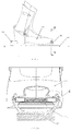
- the concept of the invention is based on an assembly as a two-part system, one called the “retractable pins”, housed in the front end of the shoe, and the other called the “front unit”, fixed onto the sliding or rolling device.
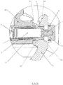
- a retractable pins device capable of being housed within a sports shoe, comprising two pins intended each to be inserted into a recess of a front unit, characterised in that it comprises two pins that are each able to slide at least 1.5 mm into a bushing, and a spring which acts to separate the two pins.
- the retractable pins device may be hidden in the toe end of a sports shoe, traversing the width of the shoe along an axis transverse to the walking direction and approximately parallel to the shoe's sole.
- It is an insert comprising two retractable pins whose ends laterally extend by at least 1.5 millimetres from the front end of the shoe, each guided within a bushing, and a spring placed between the two pins that exerts a force on each of the pins acting to separate them.
- the bushings may each comprise a collar which can contact a partial boss on the front unit, forming a mechanical sole holder, with the purpose of preventing the downward vertical movement of the shoe during its engagement with the front unit, and of adequately positioning the shoe so that the pins can penetrate into the recess of the front unit.
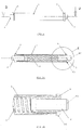
- the pins may each comprise a fillet radius or chamfer between the end of the pin on the exterior side of the shoe and the cylindrical part which is guided within the bushing.
- This fillet or chamfer assists the insertion of the pin into the recess of the front unit when clipping in (stepping in), and enables safe unclipping (safety release) according to the method in variants 1 and 2 which provides a safe unclipping system in the event the user accidentally falls.
- the mechanism assembly may be integrated into a sleeve, which is threaded at each end and into which the bushings are screwed.
- the assembly can be integrated into the toe end of the sports shoe either by gluing, pressing, or screwing.
- the toe end of the sports shoe is shaped in such a way that the retractable pins part can be inserted therein.
- the lateral parts of the toe end of the shoe preferably each comprise a flat area, parallel to each other and perpendicular to the axis of the pins, in order to create a contact area for the collar of the bushing on the shoe during assembly by the screwing of the bushing into the sleeve.
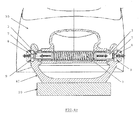
- a binding front unit Preferably the front unit is characterised in that it comprises a rigid U-shaped frame, a recess on each of the vertical parts of the frame capable of engaging with the pin of the shoe, and a release system embedded in each recess, composed of or comprising a screw, a button and a gasket, said release system being able to move at least 1.5 mm along the axis of the recess.
- the axis of the recess is preferably equal to the axis of the pins of the retractable pins device or a sports shoe having lateral pins, when the device or shoe is clipped in the front unit and ready for use, i. e. equals a rotational axis of the sports shoe about the front unit during walking.
- the axis of the recess is preferably oriented horizontally and transverse or orthogonal to a forward-backward direction.
- the front unit, fixed onto the sliding or rolling device is a rigid U-shaped frame comprising a recess in each of its vertical parts, whose axis is transverse to the direction of walking and approximately parallel to the sliding or rolling device into which the retractable pin is inserted during clipping in.
- the engagement of the shoe into the front unit is carried out by movement of the shoe from top to bottom.
- the U-shaped frame preferably comprises, on the end of each of its vertical parts, a groove in the shape of a sloping ramp so as to guide and drive the pin towards the inside of the shoe, during movement from top to bottom of the said shoe, in an intermediate phase of engagement into the front unit.
- the U-shaped frame may further comprise a mechanical sole holder on each of its vertical parts capable of engaging with the collar of the bushing, whose function is to prevent the downward vertical movement of the shoe during its engagement into the front unit, so that the pin is correctly positioned for insertion into the recess.
- a binding front unit as claimed in at least one of claims 1 to 9, may comprise a partial boss on one or each of the vertical parts of the frame and below the recess, wherein the partial boss may have a concave-shaped upper side preferably describing a part of a circle that is concentric with respect to the axis of the recess.
- Such front unit is prepared to receive a collar of a retractable pins device of the first aspect within the concave-shaped upper side of the partial boss and to carry or support such collar in order to reduce forces acting to the pins in a direction transverse to the axis of the pins, when weight of the user is applied during use.
- the front unit may comprise a downhill safety system in order to ensure releasing of the shoe from the front unit in the event the user falls when downhill skiing.
- the frame of the front unit may comprise a pivoting stirrup or a slider which can, when it is positioned in the "downhill” position, reduce the length of insertion of the pins of the shoe into the recesses of the front unit.
- Unclipping is carried out manually by the user by exerting pressure on two buttons present on the front unit, which has the effect of pushing the retractable pins towards the inside of the shoe and thus releasing the shoe from the front unit. This action is done with a pinching movement using two fingers: the thumb and preferably the index finger on the same hand.
- the release system comprises a button slidably mounted within the recess to move along an axis of the recess.
- the button may have an outer surface exposed to be pressed directly by a user's fingers to move the button along the axis of the recess towards the sports shoe such as to push the pins towards the sports shoe.
- the button in the release position the button extends through the entire length of the recess such that the recess is closed and a surface of the button facing the boot is flush with an inner rim portion of the recess.
- the button in the release position the button may be fully sunken within the recess and a surface of the button facing away from the boot may be flush with an outer rim portion of the recess.
- the recess can be a formed as a through-hole within the vertical portion of the frame.
- the bushing is disposed within a sleeve and the spring is inserted into the interior of the sleeve.
- a binding device for holding a sports shoe on a gliding or rolling device comprising a binding front unit.
- a releasing method of a sports shoe from a gliding or rolling device wherein the user carries out with the same hand a pinching movement with the thumb and another finger on the buttons of a front unit, which has the effect of releasing the shoe from the front unit.
- an assembly comprising a retractable pins device wherein the bushings each comprise a collar, and the binding front unit according to the invention, wherein the frame comprises a partial boss on each of its vertical parts and below the recess, and wherein when the retractable pins device is clipped in and the pins are received within the recesses, the collars contact the upper sides of the partial bosses.
- the collars contact the upper sides of the partial bosses such that the partial bosses support the weight of the shoe and the user during walking and/or downhill.
- the weight of the shoe and the user is at least partially carried by the collars such that forces applied to the pins in a direction transverse to the axis of the pins are reduced.
- the upper side of the partial bosses have a concave shape corresponding to the outer convex shape of the collars such that the collars fit into the concave shape of the bosses and are reliably hold and supported even if the collars rotate together with a sports shoe according to the rotation of the shoe about the axis of the pins during walking.
- a gliding or rolling device which it is equipped with a front unit.
- an assembly for the binding of a sports shoe on a gliding or rolling device comprising a front unit presenting a recess on each of its vertical parts, and a shoe comprising a pin on each of its front lateral parts, wherein the recess is capable of receiving the pin and in that the front unit is capable of receiving the shoe.
- the invention can be carried out according to parts of an embodiment described below.
- the binding comprises two distinct assemblies:
Landscapes
- Footwear And Its Accessory, Manufacturing Method And Apparatuses (AREA)
Claims (11)
- Bindungsfronteinheit (40) zum Halten eines Sportschuhs auf einer Gleit- oder Rollvorrichtung (20), wobei sie aufweist:- einen Rahmen (5) mit einer Vertiefung (6) in einem vertikalen Abschnitt zur Aufnahme eines Stifts (3), der seitlich von dem Sportschuh vorsteht,gekennzeichnet durch- ein Lösesystem (7, 8), das in der Vertiefung (6) des Rahmens (5) aufgenommen ist und in der Vertiefung entlang der Achse der Vertiefung bewegbar ist, um den Stift (3) zu dem Schuh hin zu drücken, um den Schuh (30) von der Fronteinheit (40) zu lösen.
- Die Bindungsfronteinheit (40) nach Anspruch 1, dadurch gekennzeichnet, dass sie einen starren U-förmigen Rahmen (5), eine Vertiefung (6) an jedem der vertikalen Teile des Rahmens (5), die zum Eingriff mit dem Stift (3) des Schuhs (30) in der Lage ist, sowie ein Lösesystem, das in jede Vertiefung (6) eingebettet ist, aufweist, wobei das Lösesystem dazu ausgelegt ist, sich um wenigstens 1,5mm entlang der Achse der Vertiefung (6) zu bewegen, und bevorzugt eine Schraube (7), einen Knopf (8) und eine Dichtung (9) aufweist.
- Die Bindungsfronteinheit (40) nach zumindest einem der Ansprüche 1 und 2, dadurch gekennzeichnet, dass der Rahmen (5) an einem oder dem Ende jedes seiner vertikalen Teile eine Nut (80) in der Form einer geneigten Rampe aufweist, um während einer Bewegung des Schuhs von oben nach unten in einer Zwischenphase zum Einschnappen in die Fronteinheit den Stift zum Inneren des Schuhs (30) zu führen und zu drücken.
- Die Bindungsfronteinheit (40) nach zumindest einem der Ansprüche 1 bis 3, dadurch gekennzeichnet, dass der Rahmen (5) an einem oder jedem seiner vertikalen Teile unter der Vertiefung (6) einen Teilansatz (70) aufweist, der zum Eingriff mit einem Kragen (60) einer Buchse (40) oder mit einem Ansatz eines Sportschuhs in der Lage ist, dessen Funktion es ist, die vertikale Bewegung des Schuhs (30) von oben nach unten während seines Einschnappens in die Fronteinheit zu stoppen, so dass der Stift (3) für das Einsetzen in die Vertiefung (6) korrekt positioniert ist; wobei der Teilansatz (70) bevorzugt eine konkave oder flache Form hat.
- Die Bindungsfronteinheit (40) nach zumindest einem der Ansprüche 1 bis 4, dadurch gekennzeichnet, dass sie ein Sicherheitssystem für Bergabfahrt aufweist, das, wenn es aktiviert ist, das Lösen des Schuhs von der Fronteinheit erlaubt, wenn der Benutzer unbeabsichtigt fällt, wobei das Sicherheitssystem einen Mechanismus aufweist, der die Reduktion der Eindringlänge der Stifte (3) in die Vertiefungen (6) ermöglicht, wenn der Sportschuh in die Fronteinheit eingeschnappt ist.
- Die Bindungsfronteinheit nach Anspruch 5, dadurch gekennzeichnet, dass das Sicherheitssystem für Bergabfahrt einen Beschlag (10) aufweist, der an jedem der vertikalen Teile des Rahmens (5a) angeordnet ist, wobei er in der Lage ist, um eine Achse zu schwenken, die angenähert parallel zur Gehrichtung und zur Gleit- oder Rollvorrichtung ist, und in der Lage ist, in einem Hohlraum (100) des Knopfs (8a) arretiert zu werden, wenn er in der Bergabfahrposition oder der hohen Position ist, in der sich der Beschlag erstreckt, um den Knopf (8a) zum Inneren des Schuhs (30) zurückzudrücken, wodurch die in die Vertiefung (6) vorstehende Länge des Stifts (3) reduziert wird.
- Die Bindungsfronteinheit (40) nach Anspruch 5, dadurch gekennzeichnet, dass das Sicherheitssystem für Bergabfahrt einen Schieber (11) aufweist, der auf jedem der vertikalen Teile des Rahmens (5b) angeordnet ist, wobei er in der Lage ist, um die Länge oder entlang dem vertikalen Teil des Rahmens (5b) zu gleiten, das mit einer schrägen Rampe (110) ausgestattet ist, und in der Lage ist, in einen Hohlraum (100) des Knopfs (8a) gesetzt zu werden, wenn er in der Bergabposition oder der hohen Position ist, in der sich der Schieber streckt, um den Knopf (8a) zum Inneren des Schuhs (30) zurückzudrücken, wodurch die in die Vertiefung (6) vorstehende Länge des Stifts (3) reduziert wird.
- Die Bindungsfronteinheit (40) nach zumindest einem der vorhergehenden Ansprüche, dadurch gekennzeichnet, dass die Fronteinheit eingestellt werden kann zu- einer Gehposition, die zum Gehen geeignet ist, in der das Lösesystem das Eindringen eines Stifts (3) eines Sportschuhs (30) in die Vertiefung (6) gemäß einer ersten vorbestimmten Tiefe der Vertiefung (6) erlaubt,- einer Bergabfahrposition, die für Abfahrt geeignet ist, worin das Lösesystem die Eindringlänge des Stifts (3) in die Vertiefung (6) reduziert, indem es die Tiefe der Vertiefung (6) zu einer zweiten vorbestimmten Tiefe reduziert, die kleiner als die erste vorbestimmte Tiefe ist, und- einer Löseposition, die zum Steigen in oder aus der Bindung geeignet ist, worin das Lösesystem die Tiefe der Vertiefung (6) weiter reduziert, bis der Stift (3) aus der Vertiefung (6) gelöst ist.
- Die Bindungsfronteinheit (40) nach Anspruch 8, dadurch gekennzeichnet, dass sie ferner einen Arretiermechanismus (10; 11) zum Arretieren des Lösesystems in der Bergabfahrposition aufweist.
- Anordnung, welche aufweist:- eine Bindungsfronteinheit (40) nach zumindest einem der Ansprüche 1 bis 9, wobei der Rahmen (5) einen Teilansatz (70) an jedem seiner vertikalen Teile und unter der Vertiefung (6) aufweist, und- eine Stifteinziehvorrichtung, die dazu ausgelegt ist, in einem Sportschuh aufgenommen zu werden, welche zwei Stifte (3) aufweist, die jeweils zum Einsetzen in eine Vertiefung (6) der Fronteinheit (40) ausgelegt sind, wobei die Stifteinziehvorrichtung zwei Stifte (3) aufweist, die jeweils dazu ausgelegt sind, um wenigstens 1,5mm in eine Buchse (4) zu gleiten, sowie eine Feder (2), die die Wirkung hat, die zwei Stifte (3) zu trennen, wobei die Buchse (4) an jeder von entgegengesetzten Seiten der Buchse (4) einen Kragen (60) aufweist,wobei, wenn die Stifteinziehvorrichtung eingeschnappt wird und die Stifte (3) in den Vertiefungen (6) aufgenommen sind, die Krägen (60) die Oberseite der Teilansätze (70) kontaktieren.
- Die Anordnung nach Anspruch 10, wobei in der Stifteinziehvorrichtung der Stift (3) eine Rundung (90) oder Abschrägung zwischen seinem zylindrischen Teil und seinem Ende an der Außenseite des Schuhs (30) aufweist, wobei die Rundung oder Abschrägung zum Eingriff mit einer Vertiefung (6) einer Fronteinheit (40) in der Lage ist, und als ihre Funktion hat, das Einsetzen des Stifts (3) in die Vertiefung (6) zu erleichtern und ein sicheres Ausschnappen einer Variante der Fronteinheit zu ermöglichen, die mit einem Sicherheitssystem für Bergabfahrt ausgestattet ist.
Applications Claiming Priority (1)
| Application Number | Priority Date | Filing Date | Title |
|---|---|---|---|
| FR1401140A FR3021228A1 (fr) | 2014-05-20 | 2014-05-20 | Butee avant de fixation de ski de randonnee |
Publications (2)
| Publication Number | Publication Date |
|---|---|
| EP2946818A1 EP2946818A1 (de) | 2015-11-25 |
| EP2946818B1 true EP2946818B1 (de) | 2017-11-15 |
Family
ID=52465389
Family Applications (1)
| Application Number | Title | Priority Date | Filing Date |
|---|---|---|---|
| EP15168446.1A Active EP2946818B1 (de) | 2014-05-20 | 2015-05-20 | Fronteinheit für eine bindungsvorrichtung und vorrichtung mit einziehbaren stiften |
Country Status (4)
| Country | Link |
|---|---|
| US (1) | US9308433B2 (de) |
| EP (1) | EP2946818B1 (de) |
| DE (1) | DE202015009539U1 (de) |
| FR (1) | FR3021228A1 (de) |
Cited By (1)
| Publication number | Priority date | Publication date | Assignee | Title |
|---|---|---|---|---|
| EP4274666A4 (de) * | 2021-01-08 | 2024-12-11 | Rottefella AS | Teil eines bindesystems |
Families Citing this family (12)
| Publication number | Priority date | Publication date | Assignee | Title |
|---|---|---|---|---|
| DE102015223117B4 (de) | 2015-11-23 | 2022-01-05 | Salewa Sport Ag | Tourenbindung mit einem Steuerkörper zur Begrenzung der Eindringtiefe |
| NO342268B1 (no) * | 2016-07-01 | 2018-04-30 | Rottefella As | Festemekanisme |
| DE102016222951A1 (de) * | 2016-11-21 | 2018-05-24 | Salewa Sport Ag | Tourenbindung zur Montage an einem Gleitbrett |
| DE102017120701A1 (de) | 2017-09-07 | 2019-03-07 | Marker Deutschland Gmbh | Ultraleichter Vorderbacken |
| EP3566754B1 (de) * | 2018-05-08 | 2022-08-17 | Fritschi AG - Swiss Bindings | Frontautomat für eine skibindung |
| DE102018209090A1 (de) | 2018-06-07 | 2019-12-12 | Salewa Sport Ag | Vordereinheit für eine Gleitbrettbindung |
| IT201900022008A1 (it) * | 2019-11-25 | 2021-05-25 | Atk Sports S R L | Inserto per scarpone da sci alpinismo, per l’aggancio dello scarpone ad un attacco da sci alpinismo |
| IT202000012502A1 (it) * | 2020-05-27 | 2021-11-27 | Atk Sports S R L | Inserto anteriore per scarpone da sci alpinismo, per l'aggancio dello scarpone ad un attacco da sci alpinismo |
| NO348287B1 (no) * | 2021-01-08 | 2024-11-11 | Rottefella As | Utløsermekansime for skibinding |
| NO348065B1 (no) * | 2021-04-30 | 2024-07-15 | Rottefella As | Skibinding med skråstilt innsteg, skisko, skibindingssystem og fremgangsmåte for å feste skisko |
| NO347176B1 (no) | 2021-11-25 | 2023-06-19 | Rottefella As | Anordning for forankring av bindingsdel i en skisko |
| DE102023136147A1 (de) * | 2023-12-20 | 2025-06-26 | 5Ive Sports Gmbh | Adaptervorrichtung zum Befestigen eines Skischuhs an einer Tourenskibindung |
Family Cites Families (8)
| Publication number | Priority date | Publication date | Assignee | Title |
|---|---|---|---|---|
| CH542633A (de) | 1971-08-11 | 1973-11-30 | Betschart Jun Alois | Selbstauslösende Skibindung |
| US3905613A (en) * | 1974-03-14 | 1975-09-16 | Calspan Corp | Ski binding |
| DE3141425C1 (de) * | 1981-10-19 | 1982-11-04 | Heinz 8391 Tiefenbach Beck | Sicherheitsbindung für Ski |
| DE3227237C1 (de) * | 1981-10-19 | 1984-01-26 | Heinz 8391 Tiefenbach Beck | Sicherheitsbindung für Ski |
| AT381458B (de) | 1985-03-25 | 1986-10-27 | Barthel Fritz | Tourenskibindung |
| AT411018B (de) * | 2001-04-11 | 2003-09-25 | Fischer Gmbh | Skibindung für langlauf- und tourenski |
| FR2945185B1 (fr) | 2009-05-05 | 2011-10-07 | Gignoux Sarl | Dispositif de fixation de ski de randonnee |
| DE102009059968A1 (de) | 2009-12-22 | 2011-06-30 | Ide Kg Des Irsara Daniele & Co | Skibindung |
-
2014
- 2014-05-20 FR FR1401140A patent/FR3021228A1/fr not_active Withdrawn
-
2015
- 2015-05-20 DE DE202015009539.9U patent/DE202015009539U1/de not_active Expired - Lifetime
- 2015-05-20 EP EP15168446.1A patent/EP2946818B1/de active Active
- 2015-05-20 US US14/717,175 patent/US9308433B2/en active Active
Non-Patent Citations (1)
| Title |
|---|
| None * |
Cited By (1)
| Publication number | Priority date | Publication date | Assignee | Title |
|---|---|---|---|---|
| EP4274666A4 (de) * | 2021-01-08 | 2024-12-11 | Rottefella AS | Teil eines bindesystems |
Also Published As
| Publication number | Publication date |
|---|---|
| US9308433B2 (en) | 2016-04-12 |
| DE202015009539U1 (de) | 2018-03-09 |
| US20150335987A1 (en) | 2015-11-26 |
| EP2946818A1 (de) | 2015-11-25 |
| FR3021228A1 (fr) | 2015-11-27 |
Similar Documents
| Publication | Publication Date | Title |
|---|---|---|
| EP2946818B1 (de) | Fronteinheit für eine bindungsvorrichtung und vorrichtung mit einziehbaren stiften | |
| EP2281614B1 (de) | Fersenteil mit zwei-armigen Vordergabel zum Einrasten mit Bolzen am Schuh | |
| US8973924B2 (en) | Device for adjusting the position of the boot support holder in a ski fastening system | |
| CN103118748A (zh) | 旅行或越野雪橇固定装置 | |
| US8936252B2 (en) | Safety binding for skiing | |
| US20100257754A1 (en) | Ski-boot with means for actuating corresponding engaging members of ski-touring bindings | |
| US9114306B2 (en) | Braking device for alpine touring ski | |
| EP2946817B1 (de) | Zehenstück für skitourenbindungen | |
| US10016672B2 (en) | Self-locking binding for telemark ski, touring ski or cross-country ski | |
| US9782663B2 (en) | Mechanism for locking longitudinally a ski-binding on a mounting plate | |
| US9901806B2 (en) | Automatic heel unit with walking configuration | |
| FR2741543A1 (fr) | Fixations pour ski de fond | |
| US9962595B2 (en) | Automatic heel unit with heel support structure | |
| RU2525476C2 (ru) | Лыжное крепление | |
| EP2766103B1 (de) | Skibindung | |
| EP2308568A1 (de) | Vordere Halterung einer Tourenskibindung mit verbesserter Verriegelung | |
| FI126938B (en) | Ski binder for elastic ski boot sole | |
| US6523852B2 (en) | Step-in snowboard binding | |
| US9220312B2 (en) | Safety ski binding system | |
| US11130045B2 (en) | Fastening device for fastening a boot to a sliding board | |
| JPS63501130A (ja) | スキ−ビンデイング | |
| EP2802390B1 (de) | Skibremse |
Legal Events
| Date | Code | Title | Description |
|---|---|---|---|
| REG | Reference to a national code |
Ref country code: DE Ref legal event code: R138 Ref document number: 202015009539 Country of ref document: DE Free format text: GERMAN DOCUMENT NUMBER IS 602015005950 |
|
| PUAI | Public reference made under article 153(3) epc to a published international application that has entered the european phase |
Free format text: ORIGINAL CODE: 0009012 |
|
| AK | Designated contracting states |
Kind code of ref document: A1 Designated state(s): AL AT BE BG CH CY CZ DE DK EE ES FI FR GB GR HR HU IE IS IT LI LT LU LV MC MK MT NL NO PL PT RO RS SE SI SK SM TR |
|
| AX | Request for extension of the european patent |
Extension state: BA ME |
|
| 17P | Request for examination filed |
Effective date: 20160427 |
|
| RBV | Designated contracting states (corrected) |
Designated state(s): AL AT BE BG CH CY CZ DE DK EE ES FI FR GB GR HR HU IE IS IT LI LT LU LV MC MK MT NL NO PL PT RO RS SE SI SK SM TR |
|
| RIC1 | Information provided on ipc code assigned before grant |
Ipc: A63C 9/08 20120101AFI20170327BHEP Ipc: A63C 9/086 20120101ALI20170327BHEP |
|
| GRAP | Despatch of communication of intention to grant a patent |
Free format text: ORIGINAL CODE: EPIDOSNIGR1 |
|
| INTG | Intention to grant announced |
Effective date: 20170529 |
|
| GRAS | Grant fee paid |
Free format text: ORIGINAL CODE: EPIDOSNIGR3 |
|
| GRAA | (expected) grant |
Free format text: ORIGINAL CODE: 0009210 |
|
| AK | Designated contracting states |
Kind code of ref document: B1 Designated state(s): AL AT BE BG CH CY CZ DE DK EE ES FI FR GB GR HR HU IE IS IT LI LT LU LV MC MK MT NL NO PL PT RO RS SE SI SK SM TR |
|
| REG | Reference to a national code |
Ref country code: CH Ref legal event code: EP Ref country code: GB Ref legal event code: FG4D Ref country code: AT Ref legal event code: REF Ref document number: 945693 Country of ref document: AT Kind code of ref document: T Effective date: 20171115 |
|
| REG | Reference to a national code |
Ref country code: IE Ref legal event code: FG4D |
|
| REG | Reference to a national code |
Ref country code: DE Ref legal event code: R096 Ref document number: 602015005950 Country of ref document: DE |
|
| REG | Reference to a national code |
Ref country code: CH Ref legal event code: NV Representative=s name: E. BLUM AND CO. AG PATENT- UND MARKENANWAELTE , CH |
|
| REG | Reference to a national code |
Ref country code: NL Ref legal event code: MP Effective date: 20171115 |
|
| REG | Reference to a national code |
Ref country code: LT Ref legal event code: MG4D |
|
| PG25 | Lapsed in a contracting state [announced via postgrant information from national office to epo] |
Ref country code: NO Free format text: LAPSE BECAUSE OF FAILURE TO SUBMIT A TRANSLATION OF THE DESCRIPTION OR TO PAY THE FEE WITHIN THE PRESCRIBED TIME-LIMIT Effective date: 20180215 Ref country code: FI Free format text: LAPSE BECAUSE OF FAILURE TO SUBMIT A TRANSLATION OF THE DESCRIPTION OR TO PAY THE FEE WITHIN THE PRESCRIBED TIME-LIMIT Effective date: 20171115 Ref country code: ES Free format text: LAPSE BECAUSE OF FAILURE TO SUBMIT A TRANSLATION OF THE DESCRIPTION OR TO PAY THE FEE WITHIN THE PRESCRIBED TIME-LIMIT Effective date: 20171115 Ref country code: NL Free format text: LAPSE BECAUSE OF FAILURE TO SUBMIT A TRANSLATION OF THE DESCRIPTION OR TO PAY THE FEE WITHIN THE PRESCRIBED TIME-LIMIT Effective date: 20171115 Ref country code: SE Free format text: LAPSE BECAUSE OF FAILURE TO SUBMIT A TRANSLATION OF THE DESCRIPTION OR TO PAY THE FEE WITHIN THE PRESCRIBED TIME-LIMIT Effective date: 20171115 Ref country code: LT Free format text: LAPSE BECAUSE OF FAILURE TO SUBMIT A TRANSLATION OF THE DESCRIPTION OR TO PAY THE FEE WITHIN THE PRESCRIBED TIME-LIMIT Effective date: 20171115 |
|
| PG25 | Lapsed in a contracting state [announced via postgrant information from national office to epo] |
Ref country code: HR Free format text: LAPSE BECAUSE OF FAILURE TO SUBMIT A TRANSLATION OF THE DESCRIPTION OR TO PAY THE FEE WITHIN THE PRESCRIBED TIME-LIMIT Effective date: 20171115 Ref country code: BG Free format text: LAPSE BECAUSE OF FAILURE TO SUBMIT A TRANSLATION OF THE DESCRIPTION OR TO PAY THE FEE WITHIN THE PRESCRIBED TIME-LIMIT Effective date: 20180215 Ref country code: GR Free format text: LAPSE BECAUSE OF FAILURE TO SUBMIT A TRANSLATION OF THE DESCRIPTION OR TO PAY THE FEE WITHIN THE PRESCRIBED TIME-LIMIT Effective date: 20180216 Ref country code: LV Free format text: LAPSE BECAUSE OF FAILURE TO SUBMIT A TRANSLATION OF THE DESCRIPTION OR TO PAY THE FEE WITHIN THE PRESCRIBED TIME-LIMIT Effective date: 20171115 Ref country code: RS Free format text: LAPSE BECAUSE OF FAILURE TO SUBMIT A TRANSLATION OF THE DESCRIPTION OR TO PAY THE FEE WITHIN THE PRESCRIBED TIME-LIMIT Effective date: 20171115 |
|
| PG25 | Lapsed in a contracting state [announced via postgrant information from national office to epo] |
Ref country code: EE Free format text: LAPSE BECAUSE OF FAILURE TO SUBMIT A TRANSLATION OF THE DESCRIPTION OR TO PAY THE FEE WITHIN THE PRESCRIBED TIME-LIMIT Effective date: 20171115 Ref country code: CY Free format text: LAPSE BECAUSE OF FAILURE TO SUBMIT A TRANSLATION OF THE DESCRIPTION OR TO PAY THE FEE WITHIN THE PRESCRIBED TIME-LIMIT Effective date: 20171115 Ref country code: DK Free format text: LAPSE BECAUSE OF FAILURE TO SUBMIT A TRANSLATION OF THE DESCRIPTION OR TO PAY THE FEE WITHIN THE PRESCRIBED TIME-LIMIT Effective date: 20171115 Ref country code: CZ Free format text: LAPSE BECAUSE OF FAILURE TO SUBMIT A TRANSLATION OF THE DESCRIPTION OR TO PAY THE FEE WITHIN THE PRESCRIBED TIME-LIMIT Effective date: 20171115 Ref country code: SK Free format text: LAPSE BECAUSE OF FAILURE TO SUBMIT A TRANSLATION OF THE DESCRIPTION OR TO PAY THE FEE WITHIN THE PRESCRIBED TIME-LIMIT Effective date: 20171115 |
|
| REG | Reference to a national code |
Ref country code: DE Ref legal event code: R097 Ref document number: 602015005950 Country of ref document: DE |
|
| PG25 | Lapsed in a contracting state [announced via postgrant information from national office to epo] |
Ref country code: SM Free format text: LAPSE BECAUSE OF FAILURE TO SUBMIT A TRANSLATION OF THE DESCRIPTION OR TO PAY THE FEE WITHIN THE PRESCRIBED TIME-LIMIT Effective date: 20171115 Ref country code: RO Free format text: LAPSE BECAUSE OF FAILURE TO SUBMIT A TRANSLATION OF THE DESCRIPTION OR TO PAY THE FEE WITHIN THE PRESCRIBED TIME-LIMIT Effective date: 20171115 Ref country code: PL Free format text: LAPSE BECAUSE OF FAILURE TO SUBMIT A TRANSLATION OF THE DESCRIPTION OR TO PAY THE FEE WITHIN THE PRESCRIBED TIME-LIMIT Effective date: 20171115 |
|
| PLBE | No opposition filed within time limit |
Free format text: ORIGINAL CODE: 0009261 |
|
| STAA | Information on the status of an ep patent application or granted ep patent |
Free format text: STATUS: NO OPPOSITION FILED WITHIN TIME LIMIT |
|
| 26N | No opposition filed |
Effective date: 20180817 |
|
| PG25 | Lapsed in a contracting state [announced via postgrant information from national office to epo] |
Ref country code: SI Free format text: LAPSE BECAUSE OF FAILURE TO SUBMIT A TRANSLATION OF THE DESCRIPTION OR TO PAY THE FEE WITHIN THE PRESCRIBED TIME-LIMIT Effective date: 20171115 |
|
| REG | Reference to a national code |
Ref country code: BE Ref legal event code: MM Effective date: 20180531 |
|
| PG25 | Lapsed in a contracting state [announced via postgrant information from national office to epo] |
Ref country code: MC Free format text: LAPSE BECAUSE OF FAILURE TO SUBMIT A TRANSLATION OF THE DESCRIPTION OR TO PAY THE FEE WITHIN THE PRESCRIBED TIME-LIMIT Effective date: 20171115 |
|
| REG | Reference to a national code |
Ref country code: IE Ref legal event code: MM4A |
|
| PG25 | Lapsed in a contracting state [announced via postgrant information from national office to epo] |
Ref country code: LU Free format text: LAPSE BECAUSE OF NON-PAYMENT OF DUE FEES Effective date: 20180520 |
|
| PG25 | Lapsed in a contracting state [announced via postgrant information from national office to epo] |
Ref country code: FR Free format text: LAPSE BECAUSE OF NON-PAYMENT OF DUE FEES Effective date: 20180531 Ref country code: IE Free format text: LAPSE BECAUSE OF NON-PAYMENT OF DUE FEES Effective date: 20180520 |
|
| PG25 | Lapsed in a contracting state [announced via postgrant information from national office to epo] |
Ref country code: BE Free format text: LAPSE BECAUSE OF NON-PAYMENT OF DUE FEES Effective date: 20180531 |
|
| GBPC | Gb: european patent ceased through non-payment of renewal fee |
Effective date: 20190520 |
|
| PG25 | Lapsed in a contracting state [announced via postgrant information from national office to epo] |
Ref country code: MT Free format text: LAPSE BECAUSE OF NON-PAYMENT OF DUE FEES Effective date: 20180520 |
|
| PG25 | Lapsed in a contracting state [announced via postgrant information from national office to epo] |
Ref country code: TR Free format text: LAPSE BECAUSE OF FAILURE TO SUBMIT A TRANSLATION OF THE DESCRIPTION OR TO PAY THE FEE WITHIN THE PRESCRIBED TIME-LIMIT Effective date: 20171115 |
|
| PG25 | Lapsed in a contracting state [announced via postgrant information from national office to epo] |
Ref country code: GB Free format text: LAPSE BECAUSE OF NON-PAYMENT OF DUE FEES Effective date: 20190520 |
|
| PG25 | Lapsed in a contracting state [announced via postgrant information from national office to epo] |
Ref country code: PT Free format text: LAPSE BECAUSE OF FAILURE TO SUBMIT A TRANSLATION OF THE DESCRIPTION OR TO PAY THE FEE WITHIN THE PRESCRIBED TIME-LIMIT Effective date: 20171115 |
|
| PG25 | Lapsed in a contracting state [announced via postgrant information from national office to epo] |
Ref country code: HU Free format text: LAPSE BECAUSE OF FAILURE TO SUBMIT A TRANSLATION OF THE DESCRIPTION OR TO PAY THE FEE WITHIN THE PRESCRIBED TIME-LIMIT; INVALID AB INITIO Effective date: 20150520 Ref country code: MK Free format text: LAPSE BECAUSE OF NON-PAYMENT OF DUE FEES Effective date: 20171115 |
|
| PG25 | Lapsed in a contracting state [announced via postgrant information from national office to epo] |
Ref country code: AL Free format text: LAPSE BECAUSE OF FAILURE TO SUBMIT A TRANSLATION OF THE DESCRIPTION OR TO PAY THE FEE WITHIN THE PRESCRIBED TIME-LIMIT Effective date: 20171115 Ref country code: IS Free format text: LAPSE BECAUSE OF FAILURE TO SUBMIT A TRANSLATION OF THE DESCRIPTION OR TO PAY THE FEE WITHIN THE PRESCRIBED TIME-LIMIT Effective date: 20180315 |
|
| REG | Reference to a national code |
Ref country code: AT Ref legal event code: UEP Ref document number: 945693 Country of ref document: AT Kind code of ref document: T Effective date: 20171115 |
|
| PGFP | Annual fee paid to national office [announced via postgrant information from national office to epo] |
Ref country code: CH Payment date: 20220519 Year of fee payment: 8 Ref country code: AT Payment date: 20220523 Year of fee payment: 8 |
|
| P01 | Opt-out of the competence of the unified patent court (upc) registered |
Effective date: 20230511 |
|
| P02 | Opt-out of the competence of the unified patent court (upc) changed |
Effective date: 20230527 |
|
| REG | Reference to a national code |
Ref country code: CH Ref legal event code: PL |
|
| REG | Reference to a national code |
Ref country code: AT Ref legal event code: MM01 Ref document number: 945693 Country of ref document: AT Kind code of ref document: T Effective date: 20230520 |
|
| PG25 | Lapsed in a contracting state [announced via postgrant information from national office to epo] |
Ref country code: LI Free format text: LAPSE BECAUSE OF NON-PAYMENT OF DUE FEES Effective date: 20230531 Ref country code: CH Free format text: LAPSE BECAUSE OF NON-PAYMENT OF DUE FEES Effective date: 20230531 Ref country code: AT Free format text: LAPSE BECAUSE OF NON-PAYMENT OF DUE FEES Effective date: 20230520 |
|
| PGFP | Annual fee paid to national office [announced via postgrant information from national office to epo] |
Ref country code: DE Payment date: 20250428 Year of fee payment: 11 |
|
| PGFP | Annual fee paid to national office [announced via postgrant information from national office to epo] |
Ref country code: IT Payment date: 20250527 Year of fee payment: 11 |