EP2947281A1 - Système de boîtier de turbine à gaz - Google Patents
Système de boîtier de turbine à gaz Download PDFInfo
- Publication number
- EP2947281A1 EP2947281A1 EP15164583.5A EP15164583A EP2947281A1 EP 2947281 A1 EP2947281 A1 EP 2947281A1 EP 15164583 A EP15164583 A EP 15164583A EP 2947281 A1 EP2947281 A1 EP 2947281A1
- Authority
- EP
- European Patent Office
- Prior art keywords
- gas turbine
- turbine housing
- ring
- radial flange
- housing element
- Prior art date
- Legal status (The legal status is an assumption and is not a legal conclusion. Google has not performed a legal analysis and makes no representation as to the accuracy of the status listed.)
- Granted
Links
- 238000011144 upstream manufacturing Methods 0.000 claims abstract description 46
- 238000000034 method Methods 0.000 claims description 3
- 238000011161 development Methods 0.000 description 8
- 230000018109 developmental process Effects 0.000 description 8
- 238000009434 installation Methods 0.000 description 7
- 238000007789 sealing Methods 0.000 description 3
- 230000001419 dependent effect Effects 0.000 description 2
- 230000005489 elastic deformation Effects 0.000 description 2
- 238000010438 heat treatment Methods 0.000 description 2
- 238000012986 modification Methods 0.000 description 2
- 230000004048 modification Effects 0.000 description 2
- 238000010276 construction Methods 0.000 description 1
- 238000001816 cooling Methods 0.000 description 1
- 238000006073 displacement reaction Methods 0.000 description 1
- 239000012530 fluid Substances 0.000 description 1
- 210000004907 gland Anatomy 0.000 description 1
- 239000000463 material Substances 0.000 description 1
- 230000000284 resting effect Effects 0.000 description 1
- 239000000725 suspension Substances 0.000 description 1
Images


Classifications
-
- F—MECHANICAL ENGINEERING; LIGHTING; HEATING; WEAPONS; BLASTING
- F01—MACHINES OR ENGINES IN GENERAL; ENGINE PLANTS IN GENERAL; STEAM ENGINES
- F01D—NON-POSITIVE DISPLACEMENT MACHINES OR ENGINES, e.g. STEAM TURBINES
- F01D9/00—Stators
- F01D9/02—Nozzles; Nozzle boxes; Stator blades; Guide conduits, e.g. individual nozzles
- F01D9/04—Nozzles; Nozzle boxes; Stator blades; Guide conduits, e.g. individual nozzles forming ring or sector
- F01D9/042—Nozzles; Nozzle boxes; Stator blades; Guide conduits, e.g. individual nozzles forming ring or sector fixing blades to stators
-
- F—MECHANICAL ENGINEERING; LIGHTING; HEATING; WEAPONS; BLASTING
- F01—MACHINES OR ENGINES IN GENERAL; ENGINE PLANTS IN GENERAL; STEAM ENGINES
- F01D—NON-POSITIVE DISPLACEMENT MACHINES OR ENGINES, e.g. STEAM TURBINES
- F01D25/00—Component parts, details, or accessories, not provided for in, or of interest apart from, other groups
- F01D25/24—Casings; Casing parts, e.g. diaphragms, casing fastenings
- F01D25/246—Fastening of diaphragms or stator-rings
-
- F—MECHANICAL ENGINEERING; LIGHTING; HEATING; WEAPONS; BLASTING
- F01—MACHINES OR ENGINES IN GENERAL; ENGINE PLANTS IN GENERAL; STEAM ENGINES
- F01D—NON-POSITIVE DISPLACEMENT MACHINES OR ENGINES, e.g. STEAM TURBINES
- F01D11/00—Preventing or minimising internal leakage of working-fluid, e.g. between stages
- F01D11/08—Preventing or minimising internal leakage of working-fluid, e.g. between stages for sealing space between rotor blade tips and stator
- F01D11/14—Adjusting or regulating tip-clearance, i.e. distance between rotor-blade tips and stator casing
- F01D11/16—Adjusting or regulating tip-clearance, i.e. distance between rotor-blade tips and stator casing by self-adjusting means
- F01D11/18—Adjusting or regulating tip-clearance, i.e. distance between rotor-blade tips and stator casing by self-adjusting means using stator or rotor components with predetermined thermal response, e.g. selective insulation, thermal inertia, differential expansion
-
- F—MECHANICAL ENGINEERING; LIGHTING; HEATING; WEAPONS; BLASTING
- F01—MACHINES OR ENGINES IN GENERAL; ENGINE PLANTS IN GENERAL; STEAM ENGINES
- F01D—NON-POSITIVE DISPLACEMENT MACHINES OR ENGINES, e.g. STEAM TURBINES
- F01D11/00—Preventing or minimising internal leakage of working-fluid, e.g. between stages
- F01D11/08—Preventing or minimising internal leakage of working-fluid, e.g. between stages for sealing space between rotor blade tips and stator
-
- F—MECHANICAL ENGINEERING; LIGHTING; HEATING; WEAPONS; BLASTING
- F05—INDEXING SCHEMES RELATING TO ENGINES OR PUMPS IN VARIOUS SUBCLASSES OF CLASSES F01-F04
- F05D—INDEXING SCHEME FOR ASPECTS RELATING TO NON-POSITIVE-DISPLACEMENT MACHINES OR ENGINES, GAS-TURBINES OR JET-PROPULSION PLANTS
- F05D2240/00—Components
- F05D2240/10—Stators
- F05D2240/11—Shroud seal segments
Definitions
- the present invention relates to a gas turbine housing assembly having a gas turbine housing member and a nozzle, a gas turbine, in particular an aeroengine gas turbine, with such a gas turbine housing assembly and a method for securing the guide ring in the flow direction axially to the gas turbine housing element of such a gas turbine housing assembly.
- a gas turbine with a gas turbine housing element and a guide ring with an outer ring is known.
- the outer ring is secured by Genzouseelementfeste spokes on the housing element, which engage radially in recesses in the outer ring.
- a shroud ring which is radially opposite a wheel lattice adjacent the playpen, is attached directly to the outer ring and engages with axial projections in recesses in the outer ring axially.
- the gas turbine housing element, the guide ring and the shroud have different thermal expansions. Due to the direct axial support between the outer and outer ring with the associated high normal forces cause the thermally induced relative radial movements wear high.
- An object of one embodiment of the present invention is to provide an improved gas turbine.
- a gas turbine housing assembly having the features of claim 1.
- the claims 14, 15 provide a gas turbine, in particular an aircraft engine gas turbine, with such a gas turbine housing assembly or a method for securing the guide ring in the flow direction axially to the gas turbine housing element of such a gas turbine housing arrangement under protection.
- Advantageous embodiments of the invention are the subject of the dependent claims.
- a gas turbine housing assembly includes a housing having one or more gas turbine housing members, a nozzle ring having in one embodiment a plurality of guide vanes defining vanes and an outer ring, and a shroud ring integral with the nozzle ring and guide vanes thereof. in particular in the flow direction below, radially adjacent to adjacent playpens with a plurality of blades.
- the guide ring in particular its guide grid and outer ring, integrally formed.
- the shroud is segmented in one embodiment or has a plurality of circumferentially adjacent segments.
- the shroud has a gland radially outwardly surrounding seal, in particular a honeycomb seal on.
- the shroud is secured in one embodiment on the gas turbine housing element axially in and / or against the flow direction and / or radially and / or circumferentially, in particular fixed. In particular, it can be fastened to a, preferably downstream, axial region directly or without intermediate element or indirectly or via one or more intermediate elements, connected to the gas turbine housing element, in particular detachably or stationarily attached thereto.
- the gas turbine housing assembly comprises an intermediate ring with a downstream end face a housing element fixed upstream stop and engages with an upstream end face of a radial flange of the intermediate ring outer ring fixed downstream stop to axially secure the guide ring in the flow direction of the gas turbine housing element, or which axially secures the guide ring in the flow direction to the gas turbine housing element.
- a gap between the radial flange and the shroud is formed in an installed position to allow movement of the radial flange radially outward or which allows a movement of the radial flange radially outward.
- an axial movement of the radial flange and / or a movement of the radial flange in the circumferential direction and / or a tilting movement of the radial flange are allowed or be.
- a movement of the radial flange radially outward may include, in particular, a widening of the radial flange in the radial direction.
- An upstream end face or an upstream stop in the sense of the present invention is an area whose outward normal is opposite to the throughflow direction of an exhaust gas flowing through the gas turbine or encloses with it an angle greater than 90 °, in particular at least substantially equal to 180 °, i. in other words facing an inlet of the gas turbine or facing away from the playpens.
- a downstream end face or an upstream stop means a surface whose outward normal is in the same direction as the flow direction or encloses an angle of less than 90 °, in particular at least substantially equal to 0 °, ie. In other words, it faces an outlet of the gas turbine or the playpens.
- the outer ring of the guide ring which is acted upon by the flow axially in the flow direction, axially supported in the flow direction with its downstream stop on the upstream end face of the radial flange of the intermediate ring, which in turn with its downstream end face axially in the flow direction at the upstream housing element fixed stop supported.
- An installation position is, in particular, a non-operating state of the stationary, uncontrolled gas turbine, whereby this particular normal or ambient temperature, in particular at least 10 ° C and / or at most 50 ° C, having.
- this particular normal or ambient temperature in particular at least 10 ° C and / or at most 50 ° C, having.
- the intermediate ring in the installed position substantially the same temperature everywhere, in particular the normal or ambient temperature, preferably also further the guide ring, the turbine housing member and / or the shroud.
- an operating position is in particular an operating state of the working person, i. fired and rotating gas turbine, in particular a design state, preferably in a take-off, landing or cruising operating point, wherein in one embodiment the guide ring, the turbine housing element, the shroud and / or the ferrule ring a temperature of at least 100 ° C, in particular at least 150 ° C has.
- the intermediate ring may have a temperature gradient, in particular between its downstream end face associated with the housing and its upstream, the outer ring of the guide ring associated end face.
- the temperature of the gas turbine casing element - and thus the downstream end face of the intermediate ring - can be significantly higher, in particular at least 50 ° C, than the temperature of the outer ring of the guide ring - and so that the upstream end face of the intermediate ring.
- the gap between the radial flange and the shroud is in one embodiment, a radial and / or axial gap, which allows a thermally induced movement of the radial flange out of the mounting position radially outward, without the shroud prevents this.
- this gap or axial and / or radial, in particular shortest, distance between the radial flange and the shroud is at least 0.5 mm, in particular at least 1 mm, in particular at least 5 mm. Additionally or alternatively, in one embodiment, this gap is at most 50 mm, in particular at most 25 mm, in particular at most 10 mm.
- the radial flange (at the latest) in an operating position on the shroud and supported in a development axially and / or radially on this form-fitting and / or frictional engagement.
- the initial or in the installed position (still) existing gap between the intermediate and shroud sealed operationally and thus reduces unwanted leakage, in particular be prevented.
- the shroud can touch the radial flange already in the installed position, preferably from radially outside.
- a contact surface of the radial flange for contacting the shroud be designed such that it is in the operating position, at least substantially, parallel to a contact surface of the shroud for contacting the radial flange. In other words, an angle by which the radial flange tilts in the radial expansion, held in the installed position.
- an axial flange of the intermediate ring, on which its radial flange is arranged has a kink for this purpose.
- the radial flange is (at the latest) in the operating position, in particular flat, on a support wall of the shroud ring, which is arranged at its the outside of the playpen radially surrounding seal.
- the radial flange forms an outer wall of a flow channel in which the playpens is arranged.
- the radial flange is acted upon and heated by the hot exhaust gas flowing through the flow duct and the playpens, which causes or intensifies the above-explained thermally induced radial expansion.
- the intermediate ring on an axial flange, which is arranged between its downstream and its upstream end face, and on which the radial flange of the intermediate ring is arranged.
- This can, as explained above, have a kink in a meridian section.
- the axial flange is or is elastically deformed in the operating position.
- the axial flange can be designed to be correspondingly elastic, in particular by appropriate choice of material and / or geometry. As a result of this elastic deformation, as explained above, the radial flange can expand radially during operation due to thermal conditions.
- downstream end face can be arranged on a further radial flange of the intermediate ring, which is tiltably coupled to the gas turbine housing element.
- this is to be understood in particular as meaning that the further radial flange of the intermediate ring is rotatably supported in a meridian section on the stop element fixed to the housing element.
- the further radial flange of the intermediate ring on its the downstream end face of the intermediate ring or the housing element fixed upstream stop opposite side have a rounding and / or an axial clearance to the gas turbine housing element, which in the meridian section a rotation of the cross section of the housing element fixed stop supporting further radial flange allows or permitted.
- a cross section of the intermediate ring rotates with a radial widening of its radial flange.
- the outer ring is attached to the gas turbine housing element by one or more radial spokes, in particular with radial play in the installed position.
- spokes in particular with radial play in the installed position.
- This is understood in particular a positive connection between radially inwardly projecting element fixed to the housing projections and radially outwardly projecting outer ring fixed projections, which secure the outer ring at least in the circumferential direction of the gas turbine housing element, in particular set.
- the guide ring is a guide ring of an internal stage or in the gas turbine housing element at least one further, downstream Leitkranz is arranged
- the housing element fixed upstream stop is arranged on a retaining ring in one embodiment
- the assembly can be simplified, in particular by the intermediate ring, in particular its further radial flange, inserted into a corresponding groove in the gas turbine housing element and then secured axially in the flow direction by the retaining ring.
- the housing element-fixed upstream stop is arranged in a circumferential groove of a bayonet catch.
- the assembly can also be simplified, in particular by the intermediate ring, in particular its further radial flange, is rotated in the circumferential groove of the bayonet verhakung in the circumferential direction and engages behind the defined by this circumferential groove housing element fixed stop.
- the housing element fixed upstream stop may alternatively be arranged on a releasably connected to the gas turbine housing element, in particular positive and / or frictional, or non-detachable, in particular cohesively, further gas turbine housing element, ie in particular the gas turbine housing part part of a turbine intermediate housing and the other gas turbine housing element Part of a housing of a (low pressure) turbine.
- the assembly can also be simplified, in particular by axially securing the intermediate ring, in particular its further radial flange, between the gas turbine casing element and the further gas turbine casing element.
- the circlip explained above is supported in a development, at least in the operating position, on the shroud radially. As a result, the shroud can take on a further functionality.
- the jacket ring in particular from radially outside, is supported radially on the intermediate ring. This allows the intermediate ring to take on a further functionality.
- a radial widening of the intermediate ring in particular a tilting of its further radial flange with corresponding tilting of a cross section of the axial flange, can bring about an advantageous radial adjustment of the jacket ring supported on it: namely, the intermediate ring, in particular its radial flange, widens radially on the outside, as well as the radially outwardly resting on it shroud is guided radially outward.
- a radial gap between the shroud, in particular a jacket-ring-tight seal, and the radially opposite playpens be optimized.
- the shroud ring so on the intermediate ring radially from that supports a radial distance between the shroud and the playpen or its outer periphery, in the installation and operating position, at least substantially, remains the same.
- the shroud is supported with a, in particular upstream, axial region radially from the outside of the intermediate ring and is preferably connected to a further, in particular downstream, axial region with the gas turbine housing element, in particular directly or without intermediate element, or indirectly or over one or more intermediate elements with these releasably or permanently connected.
- the intermediate ring can lead or expand the one, in particular upstream, axial region of the sheath ring radially outwards relative to the further, in particular downstream, housing-fixed axial region of the sheath ring, and thus to form a radial gap Optimize playpen automatically.
- the one, in particular upstream, axial region of the shroud ring which is supported radially from the outside radially on the intermediate ring, preferably also a sealing of the shroud radially outwardly surrounding seal, radially outward play or Free space, in particular a radial gap to the gas turbine housing element or an associated element, which faces it radially outward.
- the shroud is supported with a, in particular upstream, radially outwardly, in particular elastically, movable axial region radially from the outside of the intermediate ring and is preferably connected to a further, in particular downstream, axial region with the gas turbine housing element.
- the supports in particular upstream.
- Axial Scheme of the shroud from radially outside on the axial flange of the intermediate ring.
- a gas passage from one of the Leitkranz facing surface of the intermediate ring to one of these opposite surface of the intermediate ring is provided or formed, in particular by a leakage between the downstream end face and the upstream stop or corresponding passages on the axial and / or the other radial flange.
- the intermediate ring in the installed position is arranged on the guide ring and the gas turbine housing element such that a gap is formed between the radial flange of the guide ring and the cover ring, in order to move the radial flange to allow radially outward.
- Fig. 1 shows a gas turbine housing assembly according to an embodiment of the present invention in a meridian section, ie a section showing a rotational axis of the gas turbine (horizontally in Fig. 1 ), in an installation position.
- the gas turbine housing assembly has an in Fig. 1 only partially shown gas turbine housing element 10, a Leitkranz with an outer ring 20 and a shroud 30, which is the Leitkranz in the flow direction (from left to right in Fig. 1 ) Next adjacent playpen with an outer shroud 40 radially (from bottom to top in Fig. 1 ) is opposite.
- the shroud 30 has a the honeycomb radially outwardly surrounding honeycomb seal 31.
- the gas turbine housing assembly further comprises an intermediate ring 50 which engages with a downstream end face 51 a housing element fixed upstream stop 61 and an upstream end surface 52 of a radial flange 53 of the intermediate ring 50, an outer ring fixed downstream stop 22 to the guide ring in the flow direction axially (from left to right ) to the gas turbine housing element, wherein in the in Fig. 1 shown mounting position a gap s between the radial flange 53 and the shroud 30 is formed to a movement of the radial flange 53 radially outward (upward in Fig. 1 ).
- Fig. 2 shows the gas turbine housing assembly of Fig. 1 in an operating position: after the radial flange 53 has widened radially as a result of operational heating, it lies in the operating position flat against a support wall 32 of the shroud 30, which is arranged on the radially outer sealing ring 31 surrounding the playpen, and relies on this Support wall 32 from.
- a support wall 32 of the shroud 30 which is arranged on the radially outer sealing ring 31 surrounding the playpen, and relies on this Support wall 32 from.
- the radial flange 53 forms an outer wall of a flow channel 70, in which the playpens is arranged. As a result, during operation, the radial flange is acted upon by the hot exhaust gas flowing through the flow channel 70 and the playpens.
- the intermediate ring 50 has an axial flange 55, which is arranged between its downstream and upstream end face 51, 52, and on which the radial flange 53 of the intermediate ring is arranged. This points in the meridian section of the Fig. 1 a bend to hold the angle by which the radial flange 53 tilts in the radial expansion.
- the downstream end face 51 is arranged on a further radial flange 54 of the intermediate ring 50, which is tiltably hinged to the gas turbine housing element 10.
- the further radial flange 54 of the intermediate ring rotates in the meridian section of Fig. 1 . 2 around a contact point on the housing element fixed stop 61 on which it is rotatably supported for this purpose.
- the further radial flange 54 of the intermediate ring on its the downstream end face 51 of the intermediate ring or the housing element fixed upstream stop 61 opposite side (ie left in Fig. 1 ) a rounding and / or an axial clearance to the gas turbine housing element 10, which allows in the meridian section a rotation of the cross section of the housing element fixed to the stop 61 supporting further radial flange 54 or allowed.
- the outer ring 20 is fixed to the gas turbine casing member 10 by a plurality of radial spokes 11,21 with radial clearance between the radially inwardly projecting housing element fixed projections 11 and the radially outwardly projecting outer ring fixed projections 21 in the installation position, the outer ring 20 in the circumferential direction of the gas turbine housing element 10 secure.
- the Leitkranz is a Leitkranz an internal stage. Therefore, the housing member fixed upstream stop 61 is disposed on a snap ring 60 which is frictionally secured in the gas turbine housing member 10.
- the housing element fixed upstream stop is instead arranged in a circumferential groove of a bayonet Verhakung.
- the circlip 60 is integrally formed with the gas turbine housing member 10, with the further radial flange 54 and the circlip 60 then corresponding gaps in the circumferential direction (perpendicular to the plane of the Fig. 1 ), so that the further radial flange can initially be inserted axially against the flow direction and then rotated in the circumferential direction, so that its end face 51 then engages behind the stop 61.
- the explained locking ring 60 is supported in the operating position (see. Fig. 2 ) radially on the shroud 30.
- the shroud 30 in turn is supported both in the installed and the operating position with an upstream (left in Fig. 1 . 2 ) Axial Scheme of radially outside (from above in Fig. 1 ) on the intermediate ring 50 radially.
- opposite, downstream axial region is connected directly or indirectly to the gas turbine housing element.
- Fig. 1 . 2 shows the intermediate ring 50 at a radial expansion of its radial flange 53 due to the support of the upstream Axial Society of the shroud 30 this with radially outward.
- a radial gap can be kept constant, at least substantially, with respect to the playpen 40, which thermally expands radially outwards, or to the fins on its outer cover tape.
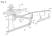
- FIG. 3 shows in Fig. 1 corresponding representation of a gas turbine housing assembly of a gas turbine according to a further embodiment of the present invention.
- Corresponding features are identified by identical reference numerals, so that reference is made to the above description and will be discussed below only differences.
- the guide ring is a last or downstream guide ring of the housing element and arranged at a module interface between a turbine intermediate housing and a low-pressure turbine.
- the housing element-fixed upstream stop 61 ' is arranged on a further gas turbine housing element 60' connected to the gas turbine housing element 10, which is part of a turbine intermediate housing, which is part of a housing of the low-pressure turbine.
Landscapes
- Engineering & Computer Science (AREA)
- Mechanical Engineering (AREA)
- General Engineering & Computer Science (AREA)
- Turbine Rotor Nozzle Sealing (AREA)
Applications Claiming Priority (1)
| Application Number | Priority Date | Filing Date | Title |
|---|---|---|---|
| DE102014209057.1A DE102014209057A1 (de) | 2014-05-14 | 2014-05-14 | Gasturbinengehäuseanordnung |
Publications (2)
| Publication Number | Publication Date |
|---|---|
| EP2947281A1 true EP2947281A1 (fr) | 2015-11-25 |
| EP2947281B1 EP2947281B1 (fr) | 2017-06-14 |
Family
ID=53008311
Family Applications (1)
| Application Number | Title | Priority Date | Filing Date |
|---|---|---|---|
| EP15164583.5A Not-in-force EP2947281B1 (fr) | 2014-05-14 | 2015-04-22 | Système de boîtier de turbine à gaz |
Country Status (4)
| Country | Link |
|---|---|
| US (1) | US9816386B2 (fr) |
| EP (1) | EP2947281B1 (fr) |
| DE (1) | DE102014209057A1 (fr) |
| ES (1) | ES2630187T3 (fr) |
Cited By (2)
| Publication number | Priority date | Publication date | Assignee | Title |
|---|---|---|---|---|
| CN109252902A (zh) * | 2018-09-14 | 2019-01-22 | 中国航发湖南动力机械研究所 | 轴向限位结构和涡轮发动机 |
| EP3000990B1 (fr) | 2014-09-26 | 2019-05-29 | Rolls-Royce plc | Dispositif de retenue de virole d'une turbine |
Families Citing this family (2)
| Publication number | Priority date | Publication date | Assignee | Title |
|---|---|---|---|---|
| DE102018210601A1 (de) * | 2018-06-28 | 2020-01-02 | MTU Aero Engines AG | Segmentring zur montage in einer strömungsmaschine |
| US12529322B1 (en) | 2024-11-08 | 2026-01-20 | Pratt & Whitney Canada Corp. | Gas turbine engine stator vane stage |
Citations (6)
| Publication number | Priority date | Publication date | Assignee | Title |
|---|---|---|---|---|
| FR2646221A1 (fr) * | 1989-04-19 | 1990-10-26 | Snecma | Joint d'etancheite, dispositif le comportant et application a une turbomachine |
| US5839878A (en) * | 1996-09-30 | 1998-11-24 | United Technologies Corporation | Gas turbine stator vane |
| EP0937864A2 (fr) * | 1998-02-20 | 1999-08-25 | Mtu Motoren- Und Turbinen-Union MàNchen Gmbh | Configuration des aubes de guidage pour une turbomachine axiale |
| US20070122270A1 (en) | 2003-12-19 | 2007-05-31 | Gerhard Brueckner | Turbomachine, especially a gas turbine |
| FR2957115A1 (fr) * | 2010-03-05 | 2011-09-09 | Snecma | Etage de turbine dans une turbomachine |
| GB2485016A (en) * | 2010-10-29 | 2012-05-02 | Gen Electric | Turbine component with resilient mounting |
Family Cites Families (6)
| Publication number | Priority date | Publication date | Assignee | Title |
|---|---|---|---|---|
| DE19756734A1 (de) * | 1997-12-19 | 1999-06-24 | Bmw Rolls Royce Gmbh | Passives Spalthaltungssystem einer Gasturbine |
| DE10312956B4 (de) * | 2003-03-22 | 2011-08-11 | MTU Aero Engines GmbH, 80995 | Anordnung für das axiale und radiale Festlegen einer Leitschaufelbaugruppe in dem Gehäuse eines Turbinentriebwerkes |
| FR2913050B1 (fr) * | 2007-02-28 | 2011-06-17 | Snecma | Turbine haute-pression d'une turbomachine |
| US8147192B2 (en) * | 2008-09-19 | 2012-04-03 | General Electric Company | Dual stage turbine shroud |
| FR2961554B1 (fr) * | 2010-06-18 | 2012-07-20 | Snecma | Secteur angulaire de redresseur pour compresseur de turbomachine, redresseur de turbomachine et turbomachine comprenant un tel secteur |
| FR2989724B1 (fr) * | 2012-04-20 | 2015-12-25 | Snecma | Etage de turbine pour une turbomachine |
-
2014
- 2014-05-14 DE DE102014209057.1A patent/DE102014209057A1/de not_active Ceased
-
2015
- 2015-04-22 ES ES15164583.5T patent/ES2630187T3/es active Active
- 2015-04-22 EP EP15164583.5A patent/EP2947281B1/fr not_active Not-in-force
- 2015-05-04 US US14/703,503 patent/US9816386B2/en not_active Expired - Fee Related
Patent Citations (6)
| Publication number | Priority date | Publication date | Assignee | Title |
|---|---|---|---|---|
| FR2646221A1 (fr) * | 1989-04-19 | 1990-10-26 | Snecma | Joint d'etancheite, dispositif le comportant et application a une turbomachine |
| US5839878A (en) * | 1996-09-30 | 1998-11-24 | United Technologies Corporation | Gas turbine stator vane |
| EP0937864A2 (fr) * | 1998-02-20 | 1999-08-25 | Mtu Motoren- Und Turbinen-Union MàNchen Gmbh | Configuration des aubes de guidage pour une turbomachine axiale |
| US20070122270A1 (en) | 2003-12-19 | 2007-05-31 | Gerhard Brueckner | Turbomachine, especially a gas turbine |
| FR2957115A1 (fr) * | 2010-03-05 | 2011-09-09 | Snecma | Etage de turbine dans une turbomachine |
| GB2485016A (en) * | 2010-10-29 | 2012-05-02 | Gen Electric | Turbine component with resilient mounting |
Cited By (3)
| Publication number | Priority date | Publication date | Assignee | Title |
|---|---|---|---|---|
| EP3000990B1 (fr) | 2014-09-26 | 2019-05-29 | Rolls-Royce plc | Dispositif de retenue de virole d'une turbine |
| CN109252902A (zh) * | 2018-09-14 | 2019-01-22 | 中国航发湖南动力机械研究所 | 轴向限位结构和涡轮发动机 |
| CN109252902B (zh) * | 2018-09-14 | 2021-09-07 | 中国航发湖南动力机械研究所 | 轴向限位结构和涡轮发动机 |
Also Published As
| Publication number | Publication date |
|---|---|
| DE102014209057A1 (de) | 2015-11-19 |
| ES2630187T3 (es) | 2017-08-18 |
| US9816386B2 (en) | 2017-11-14 |
| US20150330237A1 (en) | 2015-11-19 |
| EP2947281B1 (fr) | 2017-06-14 |
Similar Documents
| Publication | Publication Date | Title |
|---|---|---|
| EP2960438B1 (fr) | Système d'aubes de guidage variables pour une turbine à gaz et turbine à gaz dotée d'un tel système | |
| DE60016023T2 (de) | Vorrichtung mit einem spaltring zur gezielten spalteinstellung in einer gasturbine | |
| DE60318792T2 (de) | Zapfluft-Gehäuse für einen Verdichter | |
| EP3056813B1 (fr) | Joint pour un interstice marginal entre les bardeaux d'effusion d'une chambre de combustion de turbines a gaz | |
| DE2554563A1 (de) | Dichtungsanordnung fuer gasturbinentriebwerke | |
| EP2696037B1 (fr) | Joint du canal d'écoulement d'une turbomachine | |
| EP3121371B1 (fr) | Turbine comprenant des aubes directrices refroidies | |
| EP2947281B1 (fr) | Système de boîtier de turbine à gaz | |
| EP3287611A1 (fr) | Turbine à gaz et procédé de suspension d'un segment d'aube de guidage d'une turbine à gaz | |
| WO2009030197A1 (fr) | Anneau de protection multicouche pour système de propulsion d'aéronef | |
| EP2728122B1 (fr) | Fixation de support d'étanchéité pour turbomachine | |
| DE102008037501A1 (de) | Gasturbinen mit nachgiebigen Sehnengelenkdichtungen | |
| EP3153667B1 (fr) | Dispositif de sécurisation axiale d'une aube mobile et dispositif de rotor équipé d'une telle sécurisation | |
| DE102016002737A1 (de) | Turbolader mit Turbinendeckband | |
| DE112015004533T5 (de) | Variable Düseneinheit und Turbolader mit variabler Kapazität | |
| EP2799776A1 (fr) | Joint de brûleur pour tête de chambre de combustion de turbines à gaz et bouclier thermique | |
| DE3720123C2 (de) | Mantelstrom-Fan-Gasturbinen-Flugtriebwerk | |
| DE1229340B (de) | Duesenanordnung fuer Gasturbinen | |
| EP2503242A2 (fr) | Tête pour chambre de combustion avec fixation pour les joints d'étanchéité des brûleurs dans des turbines à gaz | |
| EP2955336B1 (fr) | Boîtier intermédiaire pour une turbine à gaz et turbine à gaz dotée d'un tel boîtier intermédiaire | |
| EP2428647A1 (fr) | Zone de dépassement pour une chambre de combustion d'une turbine à gaz | |
| EP3954876A1 (fr) | Bague de buse pour un turbocompresseur à gaz d'échappement | |
| EP2906807B1 (fr) | Turboréacteur avec élément de déviation inter-arbres | |
| DE60300423T2 (de) | Kühlsystem für eine Nachbrennerdüse in einer Turbomaschine | |
| EP2611992B1 (fr) | Structure de carter d'une turbomachine |
Legal Events
| Date | Code | Title | Description |
|---|---|---|---|
| PUAI | Public reference made under article 153(3) epc to a published international application that has entered the european phase |
Free format text: ORIGINAL CODE: 0009012 |
|
| AK | Designated contracting states |
Kind code of ref document: A1 Designated state(s): AL AT BE BG CH CY CZ DE DK EE ES FI FR GB GR HR HU IE IS IT LI LT LU LV MC MK MT NL NO PL PT RO RS SE SI SK SM TR |
|
| AX | Request for extension of the european patent |
Extension state: BA ME |
|
| 17P | Request for examination filed |
Effective date: 20160523 |
|
| RBV | Designated contracting states (corrected) |
Designated state(s): AL AT BE BG CH CY CZ DE DK EE ES FI FR GB GR HR HU IE IS IT LI LT LU LV MC MK MT NL NO PL PT RO RS SE SI SK SM TR |
|
| GRAP | Despatch of communication of intention to grant a patent |
Free format text: ORIGINAL CODE: EPIDOSNIGR1 |
|
| RIC1 | Information provided on ipc code assigned before grant |
Ipc: F01D 11/08 20060101ALI20170208BHEP Ipc: F01D 9/04 20060101ALI20170208BHEP Ipc: F01D 11/18 20060101ALI20170208BHEP Ipc: F01D 25/24 20060101AFI20170208BHEP |
|
| INTG | Intention to grant announced |
Effective date: 20170309 |
|
| GRAS | Grant fee paid |
Free format text: ORIGINAL CODE: EPIDOSNIGR3 |
|
| GRAA | (expected) grant |
Free format text: ORIGINAL CODE: 0009210 |
|
| AK | Designated contracting states |
Kind code of ref document: B1 Designated state(s): AL AT BE BG CH CY CZ DE DK EE ES FI FR GB GR HR HU IE IS IT LI LT LU LV MC MK MT NL NO PL PT RO RS SE SI SK SM TR |
|
| REG | Reference to a national code |
Ref country code: GB Ref legal event code: FG4D Free format text: NOT ENGLISH |
|
| REG | Reference to a national code |
Ref country code: CH Ref legal event code: EP Ref country code: AT Ref legal event code: REF Ref document number: 901178 Country of ref document: AT Kind code of ref document: T Effective date: 20170615 |
|
| REG | Reference to a national code |
Ref country code: IE Ref legal event code: FG4D Free format text: LANGUAGE OF EP DOCUMENT: GERMAN |
|
| REG | Reference to a national code |
Ref country code: DE Ref legal event code: R096 Ref document number: 502015001205 Country of ref document: DE |
|
| REG | Reference to a national code |
Ref country code: ES Ref legal event code: FG2A Ref document number: 2630187 Country of ref document: ES Kind code of ref document: T3 Effective date: 20170818 |
|
| REG | Reference to a national code |
Ref country code: NL Ref legal event code: MP Effective date: 20170614 |
|
| REG | Reference to a national code |
Ref country code: LT Ref legal event code: MG4D |
|
| PG25 | Lapsed in a contracting state [announced via postgrant information from national office to epo] |
Ref country code: HR Free format text: LAPSE BECAUSE OF FAILURE TO SUBMIT A TRANSLATION OF THE DESCRIPTION OR TO PAY THE FEE WITHIN THE PRESCRIBED TIME-LIMIT Effective date: 20170614 Ref country code: LT Free format text: LAPSE BECAUSE OF FAILURE TO SUBMIT A TRANSLATION OF THE DESCRIPTION OR TO PAY THE FEE WITHIN THE PRESCRIBED TIME-LIMIT Effective date: 20170614 Ref country code: NO Free format text: LAPSE BECAUSE OF FAILURE TO SUBMIT A TRANSLATION OF THE DESCRIPTION OR TO PAY THE FEE WITHIN THE PRESCRIBED TIME-LIMIT Effective date: 20170914 Ref country code: GR Free format text: LAPSE BECAUSE OF FAILURE TO SUBMIT A TRANSLATION OF THE DESCRIPTION OR TO PAY THE FEE WITHIN THE PRESCRIBED TIME-LIMIT Effective date: 20170915 Ref country code: FI Free format text: LAPSE BECAUSE OF FAILURE TO SUBMIT A TRANSLATION OF THE DESCRIPTION OR TO PAY THE FEE WITHIN THE PRESCRIBED TIME-LIMIT Effective date: 20170614 |
|
| PG25 | Lapsed in a contracting state [announced via postgrant information from national office to epo] |
Ref country code: SE Free format text: LAPSE BECAUSE OF FAILURE TO SUBMIT A TRANSLATION OF THE DESCRIPTION OR TO PAY THE FEE WITHIN THE PRESCRIBED TIME-LIMIT Effective date: 20170614 Ref country code: BG Free format text: LAPSE BECAUSE OF FAILURE TO SUBMIT A TRANSLATION OF THE DESCRIPTION OR TO PAY THE FEE WITHIN THE PRESCRIBED TIME-LIMIT Effective date: 20170914 Ref country code: RS Free format text: LAPSE BECAUSE OF FAILURE TO SUBMIT A TRANSLATION OF THE DESCRIPTION OR TO PAY THE FEE WITHIN THE PRESCRIBED TIME-LIMIT Effective date: 20170614 Ref country code: NL Free format text: LAPSE BECAUSE OF FAILURE TO SUBMIT A TRANSLATION OF THE DESCRIPTION OR TO PAY THE FEE WITHIN THE PRESCRIBED TIME-LIMIT Effective date: 20170614 Ref country code: LV Free format text: LAPSE BECAUSE OF FAILURE TO SUBMIT A TRANSLATION OF THE DESCRIPTION OR TO PAY THE FEE WITHIN THE PRESCRIBED TIME-LIMIT Effective date: 20170614 |
|
| PG25 | Lapsed in a contracting state [announced via postgrant information from national office to epo] |
Ref country code: CZ Free format text: LAPSE BECAUSE OF FAILURE TO SUBMIT A TRANSLATION OF THE DESCRIPTION OR TO PAY THE FEE WITHIN THE PRESCRIBED TIME-LIMIT Effective date: 20170614 Ref country code: RO Free format text: LAPSE BECAUSE OF FAILURE TO SUBMIT A TRANSLATION OF THE DESCRIPTION OR TO PAY THE FEE WITHIN THE PRESCRIBED TIME-LIMIT Effective date: 20170614 Ref country code: SK Free format text: LAPSE BECAUSE OF FAILURE TO SUBMIT A TRANSLATION OF THE DESCRIPTION OR TO PAY THE FEE WITHIN THE PRESCRIBED TIME-LIMIT Effective date: 20170614 Ref country code: EE Free format text: LAPSE BECAUSE OF FAILURE TO SUBMIT A TRANSLATION OF THE DESCRIPTION OR TO PAY THE FEE WITHIN THE PRESCRIBED TIME-LIMIT Effective date: 20170614 |
|
| PG25 | Lapsed in a contracting state [announced via postgrant information from national office to epo] |
Ref country code: IT Free format text: LAPSE BECAUSE OF FAILURE TO SUBMIT A TRANSLATION OF THE DESCRIPTION OR TO PAY THE FEE WITHIN THE PRESCRIBED TIME-LIMIT Effective date: 20170614 Ref country code: SM Free format text: LAPSE BECAUSE OF FAILURE TO SUBMIT A TRANSLATION OF THE DESCRIPTION OR TO PAY THE FEE WITHIN THE PRESCRIBED TIME-LIMIT Effective date: 20170614 Ref country code: IS Free format text: LAPSE BECAUSE OF FAILURE TO SUBMIT A TRANSLATION OF THE DESCRIPTION OR TO PAY THE FEE WITHIN THE PRESCRIBED TIME-LIMIT Effective date: 20171014 Ref country code: PL Free format text: LAPSE BECAUSE OF FAILURE TO SUBMIT A TRANSLATION OF THE DESCRIPTION OR TO PAY THE FEE WITHIN THE PRESCRIBED TIME-LIMIT Effective date: 20170614 |
|
| REG | Reference to a national code |
Ref country code: DE Ref legal event code: R097 Ref document number: 502015001205 Country of ref document: DE |
|
| PLBE | No opposition filed within time limit |
Free format text: ORIGINAL CODE: 0009261 |
|
| STAA | Information on the status of an ep patent application or granted ep patent |
Free format text: STATUS: NO OPPOSITION FILED WITHIN TIME LIMIT |
|
| REG | Reference to a national code |
Ref country code: FR Ref legal event code: PLFP Year of fee payment: 4 |
|
| PG25 | Lapsed in a contracting state [announced via postgrant information from national office to epo] |
Ref country code: DK Free format text: LAPSE BECAUSE OF FAILURE TO SUBMIT A TRANSLATION OF THE DESCRIPTION OR TO PAY THE FEE WITHIN THE PRESCRIBED TIME-LIMIT Effective date: 20170614 |
|
| 26N | No opposition filed |
Effective date: 20180315 |
|
| PG25 | Lapsed in a contracting state [announced via postgrant information from national office to epo] |
Ref country code: SI Free format text: LAPSE BECAUSE OF FAILURE TO SUBMIT A TRANSLATION OF THE DESCRIPTION OR TO PAY THE FEE WITHIN THE PRESCRIBED TIME-LIMIT Effective date: 20170614 |
|
| PG25 | Lapsed in a contracting state [announced via postgrant information from national office to epo] |
Ref country code: MT Free format text: LAPSE BECAUSE OF FAILURE TO SUBMIT A TRANSLATION OF THE DESCRIPTION OR TO PAY THE FEE WITHIN THE PRESCRIBED TIME-LIMIT Effective date: 20170614 |
|
| PG25 | Lapsed in a contracting state [announced via postgrant information from national office to epo] |
Ref country code: MC Free format text: LAPSE BECAUSE OF FAILURE TO SUBMIT A TRANSLATION OF THE DESCRIPTION OR TO PAY THE FEE WITHIN THE PRESCRIBED TIME-LIMIT Effective date: 20170614 |
|
| REG | Reference to a national code |
Ref country code: CH Ref legal event code: PL |
|
| REG | Reference to a national code |
Ref country code: BE Ref legal event code: MM Effective date: 20180430 |
|
| REG | Reference to a national code |
Ref country code: IE Ref legal event code: MM4A |
|
| PG25 | Lapsed in a contracting state [announced via postgrant information from national office to epo] |
Ref country code: LU Free format text: LAPSE BECAUSE OF NON-PAYMENT OF DUE FEES Effective date: 20180422 |
|
| PG25 | Lapsed in a contracting state [announced via postgrant information from national office to epo] |
Ref country code: BE Free format text: LAPSE BECAUSE OF NON-PAYMENT OF DUE FEES Effective date: 20180430 Ref country code: LI Free format text: LAPSE BECAUSE OF NON-PAYMENT OF DUE FEES Effective date: 20180430 Ref country code: CH Free format text: LAPSE BECAUSE OF NON-PAYMENT OF DUE FEES Effective date: 20180430 |
|
| PG25 | Lapsed in a contracting state [announced via postgrant information from national office to epo] |
Ref country code: IE Free format text: LAPSE BECAUSE OF NON-PAYMENT OF DUE FEES Effective date: 20180422 |
|
| PGFP | Annual fee paid to national office [announced via postgrant information from national office to epo] |
Ref country code: DE Payment date: 20190418 Year of fee payment: 5 Ref country code: ES Payment date: 20190520 Year of fee payment: 5 |
|
| PGFP | Annual fee paid to national office [announced via postgrant information from national office to epo] |
Ref country code: FR Payment date: 20190423 Year of fee payment: 5 |
|
| PGFP | Annual fee paid to national office [announced via postgrant information from national office to epo] |
Ref country code: GB Payment date: 20190424 Year of fee payment: 5 |
|
| PG25 | Lapsed in a contracting state [announced via postgrant information from national office to epo] |
Ref country code: TR Free format text: LAPSE BECAUSE OF FAILURE TO SUBMIT A TRANSLATION OF THE DESCRIPTION OR TO PAY THE FEE WITHIN THE PRESCRIBED TIME-LIMIT Effective date: 20170614 |
|
| PG25 | Lapsed in a contracting state [announced via postgrant information from national office to epo] |
Ref country code: PT Free format text: LAPSE BECAUSE OF FAILURE TO SUBMIT A TRANSLATION OF THE DESCRIPTION OR TO PAY THE FEE WITHIN THE PRESCRIBED TIME-LIMIT Effective date: 20170614 |
|
| PG25 | Lapsed in a contracting state [announced via postgrant information from national office to epo] |
Ref country code: MK Free format text: LAPSE BECAUSE OF NON-PAYMENT OF DUE FEES Effective date: 20170614 Ref country code: HU Free format text: LAPSE BECAUSE OF FAILURE TO SUBMIT A TRANSLATION OF THE DESCRIPTION OR TO PAY THE FEE WITHIN THE PRESCRIBED TIME-LIMIT; INVALID AB INITIO Effective date: 20150422 Ref country code: CY Free format text: LAPSE BECAUSE OF FAILURE TO SUBMIT A TRANSLATION OF THE DESCRIPTION OR TO PAY THE FEE WITHIN THE PRESCRIBED TIME-LIMIT Effective date: 20170614 |
|
| PG25 | Lapsed in a contracting state [announced via postgrant information from national office to epo] |
Ref country code: AL Free format text: LAPSE BECAUSE OF FAILURE TO SUBMIT A TRANSLATION OF THE DESCRIPTION OR TO PAY THE FEE WITHIN THE PRESCRIBED TIME-LIMIT Effective date: 20170614 |
|
| REG | Reference to a national code |
Ref country code: DE Ref legal event code: R119 Ref document number: 502015001205 Country of ref document: DE |
|
| PG25 | Lapsed in a contracting state [announced via postgrant information from national office to epo] |
Ref country code: DE Free format text: LAPSE BECAUSE OF NON-PAYMENT OF DUE FEES Effective date: 20201103 Ref country code: FR Free format text: LAPSE BECAUSE OF NON-PAYMENT OF DUE FEES Effective date: 20200430 |
|
| GBPC | Gb: european patent ceased through non-payment of renewal fee |
Effective date: 20200422 |
|
| PG25 | Lapsed in a contracting state [announced via postgrant information from national office to epo] |
Ref country code: GB Free format text: LAPSE BECAUSE OF NON-PAYMENT OF DUE FEES Effective date: 20200422 |
|
| REG | Reference to a national code |
Ref country code: AT Ref legal event code: MM01 Ref document number: 901178 Country of ref document: AT Kind code of ref document: T Effective date: 20200422 |
|
| PG25 | Lapsed in a contracting state [announced via postgrant information from national office to epo] |
Ref country code: AT Free format text: LAPSE BECAUSE OF NON-PAYMENT OF DUE FEES Effective date: 20200422 |
|
| REG | Reference to a national code |
Ref country code: ES Ref legal event code: FD2A Effective date: 20210901 |
|
| PG25 | Lapsed in a contracting state [announced via postgrant information from national office to epo] |
Ref country code: ES Free format text: LAPSE BECAUSE OF NON-PAYMENT OF DUE FEES Effective date: 20200423 |