EP2947314B1 - Spiralförmige energiespeichereinheit - Google Patents
Spiralförmige energiespeichereinheit Download PDFInfo
- Publication number
- EP2947314B1 EP2947314B1 EP13853279.1A EP13853279A EP2947314B1 EP 2947314 B1 EP2947314 B1 EP 2947314B1 EP 13853279 A EP13853279 A EP 13853279A EP 2947314 B1 EP2947314 B1 EP 2947314B1
- Authority
- EP
- European Patent Office
- Prior art keywords
- rail
- platform
- tower
- helical
- generator
- Prior art date
- Legal status (The legal status is an assumption and is not a legal conclusion. Google has not performed a legal analysis and makes no representation as to the accuracy of the status listed.)
- Not-in-force
Links
Images



Classifications
-
- F—MECHANICAL ENGINEERING; LIGHTING; HEATING; WEAPONS; BLASTING
- F03—MACHINES OR ENGINES FOR LIQUIDS; WIND, SPRING, OR WEIGHT MOTORS; PRODUCING MECHANICAL POWER OR A REACTIVE PROPULSIVE THRUST, NOT OTHERWISE PROVIDED FOR
- F03D—WIND MOTORS
- F03D13/00—Assembly, mounting or commissioning of wind motors; Arrangements specially adapted for transporting wind motor components
- F03D13/20—Arrangements for mounting or supporting wind motors; Masts or towers for wind motors
-
- E—FIXED CONSTRUCTIONS
- E04—BUILDING
- E04H—BUILDINGS OR LIKE STRUCTURES FOR PARTICULAR PURPOSES; SWIMMING OR SPLASH BATHS OR POOLS; MASTS; FENCING; TENTS OR CANOPIES, IN GENERAL
- E04H12/00—Towers; Masts or poles; Chimney stacks; Water-towers; Methods of erecting such structures
-
- F—MECHANICAL ENGINEERING; LIGHTING; HEATING; WEAPONS; BLASTING
- F03—MACHINES OR ENGINES FOR LIQUIDS; WIND, SPRING, OR WEIGHT MOTORS; PRODUCING MECHANICAL POWER OR A REACTIVE PROPULSIVE THRUST, NOT OTHERWISE PROVIDED FOR
- F03D—WIND MOTORS
- F03D13/00—Assembly, mounting or commissioning of wind motors; Arrangements specially adapted for transporting wind motor components
- F03D13/10—Assembly of wind motors; Arrangements for erecting wind motors
-
- F—MECHANICAL ENGINEERING; LIGHTING; HEATING; WEAPONS; BLASTING
- F03—MACHINES OR ENGINES FOR LIQUIDS; WIND, SPRING, OR WEIGHT MOTORS; PRODUCING MECHANICAL POWER OR A REACTIVE PROPULSIVE THRUST, NOT OTHERWISE PROVIDED FOR
- F03D—WIND MOTORS
- F03D9/00—Adaptations of wind motors for special use; Combinations of wind motors with apparatus driven thereby; Wind motors specially adapted for installation in particular locations
- F03D9/10—Combinations of wind motors with apparatus storing energy
- F03D9/11—Combinations of wind motors with apparatus storing energy storing electrical energy
-
- F—MECHANICAL ENGINEERING; LIGHTING; HEATING; WEAPONS; BLASTING
- F03—MACHINES OR ENGINES FOR LIQUIDS; WIND, SPRING, OR WEIGHT MOTORS; PRODUCING MECHANICAL POWER OR A REACTIVE PROPULSIVE THRUST, NOT OTHERWISE PROVIDED FOR
- F03D—WIND MOTORS
- F03D9/00—Adaptations of wind motors for special use; Combinations of wind motors with apparatus driven thereby; Wind motors specially adapted for installation in particular locations
- F03D9/10—Combinations of wind motors with apparatus storing energy
- F03D9/13—Combinations of wind motors with apparatus storing energy storing gravitational potential energy
- F03D9/16—Combinations of wind motors with apparatus storing energy storing gravitational potential energy using weights
-
- F—MECHANICAL ENGINEERING; LIGHTING; HEATING; WEAPONS; BLASTING
- F03—MACHINES OR ENGINES FOR LIQUIDS; WIND, SPRING, OR WEIGHT MOTORS; PRODUCING MECHANICAL POWER OR A REACTIVE PROPULSIVE THRUST, NOT OTHERWISE PROVIDED FOR
- F03D—WIND MOTORS
- F03D9/00—Adaptations of wind motors for special use; Combinations of wind motors with apparatus driven thereby; Wind motors specially adapted for installation in particular locations
- F03D9/20—Wind motors characterised by the driven apparatus
- F03D9/25—Wind motors characterised by the driven apparatus the apparatus being an electrical generator
-
- F—MECHANICAL ENGINEERING; LIGHTING; HEATING; WEAPONS; BLASTING
- F03—MACHINES OR ENGINES FOR LIQUIDS; WIND, SPRING, OR WEIGHT MOTORS; PRODUCING MECHANICAL POWER OR A REACTIVE PROPULSIVE THRUST, NOT OTHERWISE PROVIDED FOR
- F03G—SPRING, WEIGHT, INERTIA OR LIKE MOTORS; MECHANICAL-POWER PRODUCING DEVICES OR MECHANISMS, NOT OTHERWISE PROVIDED FOR OR USING ENERGY SOURCES NOT OTHERWISE PROVIDED FOR
- F03G3/00—Other motors, e.g. gravity or inertia motors
- F03G3/087—Gravity or weight motors
- F03G3/094—Gravity or weight motors specially adapted for potential energy power storage stations; combinations of gravity or weight motors with electric motors or generators
-
- F—MECHANICAL ENGINEERING; LIGHTING; HEATING; WEAPONS; BLASTING
- F05—INDEXING SCHEMES RELATING TO ENGINES OR PUMPS IN VARIOUS SUBCLASSES OF CLASSES F01-F04
- F05B—INDEXING SCHEME RELATING TO WIND, SPRING, WEIGHT, INERTIA OR LIKE MOTORS, TO MACHINES OR ENGINES FOR LIQUIDS COVERED BY SUBCLASSES F03B, F03D AND F03G
- F05B2230/00—Manufacture
- F05B2230/60—Assembly methods
- F05B2230/61—Assembly methods using auxiliary equipment for lifting or holding
-
- F—MECHANICAL ENGINEERING; LIGHTING; HEATING; WEAPONS; BLASTING
- F05—INDEXING SCHEMES RELATING TO ENGINES OR PUMPS IN VARIOUS SUBCLASSES OF CLASSES F01-F04
- F05B—INDEXING SCHEME RELATING TO WIND, SPRING, WEIGHT, INERTIA OR LIKE MOTORS, TO MACHINES OR ENGINES FOR LIQUIDS COVERED BY SUBCLASSES F03B, F03D AND F03G
- F05B2250/00—Geometry
- F05B2250/20—Geometry three-dimensional
- F05B2250/25—Geometry three-dimensional helical
-
- Y—GENERAL TAGGING OF NEW TECHNOLOGICAL DEVELOPMENTS; GENERAL TAGGING OF CROSS-SECTIONAL TECHNOLOGIES SPANNING OVER SEVERAL SECTIONS OF THE IPC; TECHNICAL SUBJECTS COVERED BY FORMER USPC CROSS-REFERENCE ART COLLECTIONS [XRACs] AND DIGESTS
- Y02—TECHNOLOGIES OR APPLICATIONS FOR MITIGATION OR ADAPTATION AGAINST CLIMATE CHANGE
- Y02B—CLIMATE CHANGE MITIGATION TECHNOLOGIES RELATED TO BUILDINGS, e.g. HOUSING, HOUSE APPLIANCES OR RELATED END-USER APPLICATIONS
- Y02B10/00—Integration of renewable energy sources in buildings
- Y02B10/30—Wind power
-
- Y—GENERAL TAGGING OF NEW TECHNOLOGICAL DEVELOPMENTS; GENERAL TAGGING OF CROSS-SECTIONAL TECHNOLOGIES SPANNING OVER SEVERAL SECTIONS OF THE IPC; TECHNICAL SUBJECTS COVERED BY FORMER USPC CROSS-REFERENCE ART COLLECTIONS [XRACs] AND DIGESTS
- Y02—TECHNOLOGIES OR APPLICATIONS FOR MITIGATION OR ADAPTATION AGAINST CLIMATE CHANGE
- Y02E—REDUCTION OF GREENHOUSE GAS [GHG] EMISSIONS, RELATED TO ENERGY GENERATION, TRANSMISSION OR DISTRIBUTION
- Y02E10/00—Energy generation through renewable energy sources
- Y02E10/70—Wind energy
- Y02E10/72—Wind turbines with rotation axis in wind direction
-
- Y—GENERAL TAGGING OF NEW TECHNOLOGICAL DEVELOPMENTS; GENERAL TAGGING OF CROSS-SECTIONAL TECHNOLOGIES SPANNING OVER SEVERAL SECTIONS OF THE IPC; TECHNICAL SUBJECTS COVERED BY FORMER USPC CROSS-REFERENCE ART COLLECTIONS [XRACs] AND DIGESTS
- Y02—TECHNOLOGIES OR APPLICATIONS FOR MITIGATION OR ADAPTATION AGAINST CLIMATE CHANGE
- Y02E—REDUCTION OF GREENHOUSE GAS [GHG] EMISSIONS, RELATED TO ENERGY GENERATION, TRANSMISSION OR DISTRIBUTION
- Y02E10/00—Energy generation through renewable energy sources
- Y02E10/70—Wind energy
- Y02E10/728—Onshore wind turbines
-
- Y—GENERAL TAGGING OF NEW TECHNOLOGICAL DEVELOPMENTS; GENERAL TAGGING OF CROSS-SECTIONAL TECHNOLOGIES SPANNING OVER SEVERAL SECTIONS OF THE IPC; TECHNICAL SUBJECTS COVERED BY FORMER USPC CROSS-REFERENCE ART COLLECTIONS [XRACs] AND DIGESTS
- Y02—TECHNOLOGIES OR APPLICATIONS FOR MITIGATION OR ADAPTATION AGAINST CLIMATE CHANGE
- Y02E—REDUCTION OF GREENHOUSE GAS [GHG] EMISSIONS, RELATED TO ENERGY GENERATION, TRANSMISSION OR DISTRIBUTION
- Y02E60/00—Enabling technologies; Technologies with a potential or indirect contribution to GHG emissions mitigation
- Y02E60/16—Mechanical energy storage, e.g. flywheels or pressurised fluids
-
- Y—GENERAL TAGGING OF NEW TECHNOLOGICAL DEVELOPMENTS; GENERAL TAGGING OF CROSS-SECTIONAL TECHNOLOGIES SPANNING OVER SEVERAL SECTIONS OF THE IPC; TECHNICAL SUBJECTS COVERED BY FORMER USPC CROSS-REFERENCE ART COLLECTIONS [XRACs] AND DIGESTS
- Y02—TECHNOLOGIES OR APPLICATIONS FOR MITIGATION OR ADAPTATION AGAINST CLIMATE CHANGE
- Y02E—REDUCTION OF GREENHOUSE GAS [GHG] EMISSIONS, RELATED TO ENERGY GENERATION, TRANSMISSION OR DISTRIBUTION
- Y02E70/00—Other energy conversion or management systems reducing GHG emissions
- Y02E70/30—Systems combining energy storage with energy generation of non-fossil origin
-
- Y—GENERAL TAGGING OF NEW TECHNOLOGICAL DEVELOPMENTS; GENERAL TAGGING OF CROSS-SECTIONAL TECHNOLOGIES SPANNING OVER SEVERAL SECTIONS OF THE IPC; TECHNICAL SUBJECTS COVERED BY FORMER USPC CROSS-REFERENCE ART COLLECTIONS [XRACs] AND DIGESTS
- Y02—TECHNOLOGIES OR APPLICATIONS FOR MITIGATION OR ADAPTATION AGAINST CLIMATE CHANGE
- Y02P—CLIMATE CHANGE MITIGATION TECHNOLOGIES IN THE PRODUCTION OR PROCESSING OF GOODS
- Y02P70/00—Climate change mitigation technologies in the production process for final industrial or consumer products
- Y02P70/50—Manufacturing or production processes characterised by the final manufactured product
Definitions
- the invention belongs to the field of the Energy Industry and, especially, to the field of renewable energies, wherein the production of electric power cannot be regulated, owing to the uncertainties of Nature, which is not a constant source of energy, and it is necessary that the energy is stored, so that a supply of energy is available during those periods where a renewable source of energy is not available, or during the peak hours of the day, where the power output cannot meet the energy demand.
- a specific design is used, that can be modified and adapted to be used in sectors with similar needs. This design allows to use a self-erecting tower, without the need for large cranes or special transportation means for its assembly.
- a minimum gradient is required between the two reservoir levels.
- This method does not allow a modular and staged construction, with a staggered investment that is reasonable and allowable for any economy.
- the sites are very specific, and the affected areas are vary large.
- This method does not allow a modular and staged construction, with a staggered investment that is reasonable and allowable for any economy.
- thermosolar plants This method is used by thermosolar plants only.
- Each pipe, or each time the oil passes through the exchanger represents a loss of performance; furthermore, the high temperatures involve high pressures, and thus, very specific facilities, since salt is very corrosive and the properties of materials decrease over temperature.
- This method does not allow a modular and staged construction, with a staggered investment that is reasonable and allowable for any economy.
- this "Helical Energy Storage Unit” represents an integral system for the storage of excess power obtained from the output generated by renewable power plants and for the construction of towers, which is especially suitable for the wind power generation industry, considering the geometry of the invention, but that can be also adapted to any other power generation system, both of a renewable or conventional type, without requiring any specific location or technologies, huge investments or third processes.
- the invention does neither require any specific civil works since it makes possible to dispense with special transportation means and large cranes, since the tower sections are erected by means of their own self-erection mechanism.
- the operation of the process that will be described hereinafter is based on the conversion of the excess of power into kinetic energy and its storage as potential energy.
- the process would consist of the rising of a platform, by means of a gear operated by an engine, along a toothed ramp, with a specific load and slope, and the subsequent release of the brake and the conversion of the engine into a generator.
- the ramp has the peculiarity that it becomes a helix inside a straight cylinder (it would not be so advantageous if the conversion would occur outside the cylinder) which rises vertically the assembly up to the point where it is required, and then, the assembly falls to recover the energy supplied.
- the rising platform allows the adaptation of a simple tool for the hoisting of the different sections, which in turn allows the self-erection of the tower.
- the helical energy storage unit that is the object of this invention stores energy thanks to the assembly of its different components, to obtain a complete mechanism.
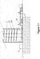
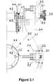
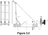
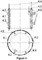
- Such components are: 1 Foundations; 2 Tower (2.1 structure, 2.2 multi-track helical rail; 2.3 connectors); 3 Rotating platform (3.1 guide bases, 3.2 generators, 3.3 hydraulic brake assembly, 3.4 swan neck arms, 3.5 main platform, 3.6 weights and 3.7 ancillary items); 4 Power collector (4.1 central collector, 4.2 sensors, 4.3 insulated contact lines and 4.4 guiding lines); 5 elevator-staircase; 6 transformer station and 7 Dome (7.1 dome and 7.2 nacelle adapting reel, nacelle power collector).
- 1 Foundations 2 Tower (2.1 structure, 2.2 multi-track helical rail; 2.3 connectors); 3 Rotating platform (3.1 guide bases, 3.2 generators, 3.3 hydraulic brake assembly, 3.4 swan neck arms, 3.5 main platform, 3.6 weights and 3.7 ancillary items); 4 Power collector (4.1 central collector, 4.2 sensors, 4.3 insulated
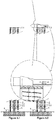
- the mechanics of the helical energy storage unit according to this invention can be inferred from the assembly of the components within the drawings (the numbering depends on the group and subgroup): detailed view of the foundations and autonomous unloading of sections ( figure 1.1 ); tower ( figure 2.1 ), detailed view of the rail support ( figure 2.2 ) and detail of connectors ( figures 2.3.1 and 2.3.2 ); platform ( figure 3 ), detailed view of the platform ( figure 3.1 ) and detailed view of the ancillary hoisting element (3.2); power collector ( figure 4 ); dome ( figure 5.1 ), nacelle adaptation reel ( figure 5.2 ).
- the final shape of the components may be different, as it must be adapted to the different requirements in terms of load, market economy or client, although the main function will remain unchanged.
- Metal items are processed from commercial-grade metal sections, that are machined according to their intended use, i.e., cut, sandblasted, folded, trimmed, and milled, that are very common processes. Joints will be made by welding and screwing. The torque will be verified for all screwed items.
- the relevant geometry may vary according to the final use, dimensions, weight, materials... but the main functions of the components remain unaltered.
- the tower requires the help of a crane (70Ton) at the first ring, until the platform is installed.
- the remaining concrete slabs will be autonomously hoisted from the platform.
- the central body of each connector will be expanded by induction.
- the helical energy storage unit as a result of its autonomous assembly, can be used either as a wind generator tower, as a reservoir or in any other way, in all those processes where the storage of power is required, i.e., the storage of potential energy obtained from electric power, for its subsequent conversion and reuse; both during peak and off-peak hours. It represents an increase in the energy efficiency and the optimisation of renewable resources, as it allows the use of power ranges below those currently required for feed-in purposes. Integration of renewable resources.
- the invention allows to group the facilities from the time of their construction, for instance, in wind farms. Increase of the independence of the renewable natural resources vis-à-vis energy demand.
- the invention does not require special sites, water resources, large civil works or third processes and is, therefore, perfectly suitable for all kinds economies and locations. It does not generate a significant environmental impact, and does neither use non-recyclable chemicals nor heavy (radioactive) metals in any of the manufacturing and installation stages. Therefore, it is very suitable to preserve the environment and maintain local economy. It is indicated for locations that are prone to undergo seismic hazards, since tits failure does not involve any environmental disasters (of a nuclear, hydraulic, thermal etc. nature).
- the invention is applicable to the whole energy industry sector, which suffers a series of similar problems, and to any civil or food and agriculture sector which may profit from its advantages (silos, reservoirs, large columns, etc.)
Landscapes
- Engineering & Computer Science (AREA)
- Chemical & Material Sciences (AREA)
- Combustion & Propulsion (AREA)
- General Engineering & Computer Science (AREA)
- Mechanical Engineering (AREA)
- Sustainable Development (AREA)
- Sustainable Energy (AREA)
- Life Sciences & Earth Sciences (AREA)
- Power Engineering (AREA)
- Architecture (AREA)
- Civil Engineering (AREA)
- Structural Engineering (AREA)
- Wind Motors (AREA)
Claims (7)
- Spiralförmige Energiespeichereinheit, dadurch gekennzeichnet, dass sie Folgendes umfasst:- Fundamente (1), auf denen ein Turm (2) errichtet wird, wobei ein solcher Turm hohl ist und die Form eines geraden Zylinders aufweist;- eine mehrspurige Schiene (2.2), welche sich erstreckt, indem sie einem spiralförmigen Pfad folgt, wobei sie mit der Innenwand (2.1) des Turms (2) verbunden ist;- eine Plattform zum Speichern der potentiellen Energie (3), welche angepasst ist, um sich entlang der solchen spiralförmigen Schiene zum Speichern der potentiellen Energie zu bewegen, während sie entlang einer solchen Schiene aufsteigt, und um kinetische Energie zu erzeugen, wenn sie entlang der Schiene abfällt;- mindestens einen Generator/Elektromotor (3.2), welcher fest auf der Speicherplattform (3) montiert ist und mit der mehrspurigen Schiene (2.2) in Eingriff steht, um elektrischen Strom aus der kinetischen Energie, welche freigesetzt wird, wenn eine solche Speicherplattform entlang der Schiene abfällt, zu erzeugen und um als Motor zum Ermöglichen des Aufsteigens der Speicherplattform (3) entlang einer solchen Schiene (2.2) verwendet zu werden;- eine Speichervorrichtung (4), welche funktionell mit dem Generator/Elektromotor (3.2) gekoppelt ist und angepasst ist, um den Strom, welcher erzeugt wird, wenn die Plattform entlang der Schiene (2.2) abfällt, zu sammeln und um Strom zum Ermöglichen des Aufsteigens einer solchen Speicherplattform (3) entlang der Schiene zuzuführen;- eine Umwandlungsstation (6), welche mit der Speichervorrichtung (4) verbunden ist, um den Strom zu sammeln, welcher während des Abfallens der Speicherplattform (3) entlang der Schiene, wenn die Generatorgruppe/der Elektromotor (3.2) als Generatorgruppe funktioniert, erzeugt wird, oder um Strom zu einem solchen Generator/Elektromotor (3.2) zuzuführen, wenn ein solcher Generator/Elektromotor als Motor zum Aufsteigen der Speicherplattform (3) entlang der Schiene funktioniert; undwobei die Speicherplattform (3) Hilfshebeelemente (3.7) zur autonomen Montage des Turms (2) umfasst.
- Spiralförmige Energiespeichereinheit nach Anspruch 1, dadurch gekennzeichnet, dass die spiralförmige Schiene (2.2) Folgendes umfasst:- mindestens eine erste Spur zum Tragen einer Führungsbasis (3.1) des Generators/Elektromotors (3.2);- mindestens eine zweite Spur zum Koppeln mit der kinematischen Einspeisung/Ausspeisung des Generators/Elektromotors (3.2); und- mindestens eine dritte Spur, welche funktionell mit einer hydraulischen Bremsvorrichtung (3.3), die an der Speicherplattform (3) vorgesehen ist, gekoppelt ist.
- Spiralförmige Energiespeichereinheit nach mindestens einem der Ansprüche 1 und 2, dadurch gekennzeichnet, dass die Speicherplattform (3) eine Hauptplattform (3.5) im Wesentlichen in der Form eines Rings umfasst, welcher im Wesentlichen koaxial zu dem Innenzylinder des Turms (2) ist, in dem er montiert ist, und wobei sich ein vertikal einstellbarer Schwanenhalsarm (3.4) erstreckt, indem er einer Radialrichtung folgt, und welche mindestens eine Generatorgruppe/einen Elektromotor (3.2) enthält und vorzugsweise drei gleichmäßig beabstandete Schwanenhalsarme zum Tragen der jeweiligen Generatorgruppe/Elektromotoren enthält, und wobei eine Reihe von Gewichten (3.6) an der Hauptplattform fest eingebaut wurde, um die Masse der Speicherplattform zu erhöhen; wobei die Stromspeichereinheit (4) aus einem hohlen zylindrischen Körper besteht, welcher koaxial in der zentralen Öffnung der Hauptplattform (3.5) angeordnet ist und welcher entlang einer Reihe von Führungssträngen (4.4) simultan zu der Bewegung der Speicherplattform (3) bewegt werden kann, wobei eine Reihe von Sensoren (4.2) bereitgestellt wurde, um die Speichervorrichtung (4) mit der Stromeinspeisung/-ausspeisung von mindestens einem Generator/Elektromotor (3.2) elektrisch zu verbinden.
- Spiralförmige Energiespeichereinheit nach mindestens einem der vorhergehenden Ansprüche 1 bis 3, dadurch gekennzeichnet, dass der Turm (2), mit Ausnahme der Endringen, in identische Betonplattenabschnitte unterteilt ist, deren Länge geregelt ist, um eine flache Einfassung zu erhalten; wobei jeder Betonplattenabschnitt den entsprechenden Abschnitt der spiralförmigen Schiene (2.2) einbezieht.
- Spiralförmige Energiespeichereinheit nach mindestens einem der vorhergehenden Ansprüche 1 bis 4, dadurch gekennzeichnet, dass die spiralförmigen Schienenabschnitte durch Folgendes gekoppelt sind:- Wärmeausdehnungsverbindungsstücke (2.3.2), welche in den entsprechenden Gehäusen (2.3.2"), die jeweils an dem Schienenabschnitt bereitgestellt sind, aufgenommen sind; und- bolzenartige Verbindungsstücke (2.3.1-2, 2.3.1", 2.3.1, 2.3.1"), welche innerhalb der Seitenwand (2.1) des Turms (2) gekoppelt werden können.
- Spiralförmige Energiespeichereinheit nach mindestens einem der vorhergehenden Ansprüche 1 bis 5, dadurch gekennzeichnet, dass das obere Ende des Turms (2) in einer Kuppel (7.1) endet, wobei eine solche Kuppel zum Koppeln einer Gondel (7.2) eines Windgenerators angepasst ist.
- Spiralförmige Energiespeichereinheit nach Anspruch 6, dadurch gekennzeichnet, dass die Gondel (7.2) drehbar auf der Kuppel (7.1) montiert ist, sodass sie sich kontinuierlich während der Ausrichtung der Gondel drehen kann.
Priority Applications (2)
| Application Number | Priority Date | Filing Date | Title |
|---|---|---|---|
| DK17190321.4T DK3284883T3 (da) | 2012-11-12 | 2013-11-12 | Selvrejsende tårn |
| EP17190321.4A EP3284883B1 (de) | 2012-11-12 | 2013-11-12 | Selbsterrichtender turm |
Applications Claiming Priority (2)
| Application Number | Priority Date | Filing Date | Title |
|---|---|---|---|
| ES201201037U ES1090131Y (es) | 2012-11-12 | 2012-11-12 | Acumulador energético helicoidal |
| PCT/ES2013/070788 WO2014072565A1 (es) | 2012-11-12 | 2013-11-12 | Acumulador energético helicoidal |
Related Child Applications (1)
| Application Number | Title | Priority Date | Filing Date |
|---|---|---|---|
| EP17190321.4A Division EP3284883B1 (de) | 2012-11-12 | 2013-11-12 | Selbsterrichtender turm |
Publications (3)
| Publication Number | Publication Date |
|---|---|
| EP2947314A1 EP2947314A1 (de) | 2015-11-25 |
| EP2947314A4 EP2947314A4 (de) | 2016-11-02 |
| EP2947314B1 true EP2947314B1 (de) | 2017-10-11 |
Family
ID=49165424
Family Applications (2)
| Application Number | Title | Priority Date | Filing Date |
|---|---|---|---|
| EP13853279.1A Not-in-force EP2947314B1 (de) | 2012-11-12 | 2013-11-12 | Spiralförmige energiespeichereinheit |
| EP17190321.4A Active EP3284883B1 (de) | 2012-11-12 | 2013-11-12 | Selbsterrichtender turm |
Family Applications After (1)
| Application Number | Title | Priority Date | Filing Date |
|---|---|---|---|
| EP17190321.4A Active EP3284883B1 (de) | 2012-11-12 | 2013-11-12 | Selbsterrichtender turm |
Country Status (6)
| Country | Link |
|---|---|
| EP (2) | EP2947314B1 (de) |
| DK (1) | DK3284883T3 (de) |
| ES (2) | ES1090131Y (de) |
| NO (1) | NO2947314T3 (de) |
| PT (1) | PT3284883T (de) |
| WO (1) | WO2014072565A1 (de) |
Family Cites Families (10)
| Publication number | Priority date | Publication date | Assignee | Title |
|---|---|---|---|---|
| CH202310A (de) * | 1938-09-07 | 1939-01-15 | Stalder Oskar | Windkraftwerk. |
| DE2146689A1 (de) * | 1970-09-25 | 1972-03-30 | Ragnar O. Lindholm AB, Karlstad (Schweden) | Verfahren und Anordnung zum Errichten von Turmkonstruktionen |
| DE3333715C2 (de) * | 1983-09-17 | 1986-01-09 | Walter 5300 Bonn Schönball | Windkraftmaschine mit einer Anordnung zur Anpassung des Windrades an den elektrischen Generator |
| PT1057770E (pt) * | 1999-06-03 | 2005-11-30 | D H Blattner & Sons Inc | Plataforma de elevacao ascensional num carril-guia e metodo |
| US6220394B1 (en) * | 1999-10-21 | 2001-04-24 | The Long Now Foundation | Weight operated mechanical drive |
| JP2003239842A (ja) * | 2002-02-14 | 2003-08-27 | Kazuma Nakamura | 風力エネルギーを位置エネルギーとして蓄積しながら同時に電力エネルギーとして引き出すための風力発電装置 |
| GB2412697A (en) * | 2004-03-30 | 2005-10-05 | Primera Consultancy And Design | Wind turbine |
| DE102006003897A1 (de) * | 2006-01-27 | 2007-08-02 | Elotech Electronic Gmbh | Speicherwindrad zur Erzeugung von elektrischer Energie mit mechanischen Energie-Zwischen-Speichern |
| BR112012000808A2 (pt) * | 2009-07-13 | 2016-02-23 | Vsl Int Ag | conjunto de torre telescópica e método |
| DE102012203883B4 (de) * | 2012-03-13 | 2019-09-05 | Gerhard Stasch | Verfahren zur Errichtung eines Turms |
-
2012
- 2012-11-12 ES ES201201037U patent/ES1090131Y/es not_active Expired - Fee Related
-
2013
- 2013-11-12 PT PT171903214T patent/PT3284883T/pt unknown
- 2013-11-12 EP EP13853279.1A patent/EP2947314B1/de not_active Not-in-force
- 2013-11-12 WO PCT/ES2013/070788 patent/WO2014072565A1/es not_active Ceased
- 2013-11-12 EP EP17190321.4A patent/EP3284883B1/de active Active
- 2013-11-12 DK DK17190321.4T patent/DK3284883T3/da active
- 2013-11-12 NO NO13853279A patent/NO2947314T3/no unknown
- 2013-11-12 ES ES17190321T patent/ES2829281T3/es active Active
Non-Patent Citations (1)
| Title |
|---|
| None * |
Also Published As
| Publication number | Publication date |
|---|---|
| EP3284883B1 (de) | 2020-08-05 |
| ES1090131U (es) | 2013-09-25 |
| EP2947314A4 (de) | 2016-11-02 |
| PT3284883T (pt) | 2020-11-03 |
| WO2014072565A1 (es) | 2014-05-15 |
| NO2947314T3 (de) | 2018-03-10 |
| DK3284883T3 (da) | 2020-10-19 |
| ES1090131Y (es) | 2013-12-18 |
| ES2829281T3 (es) | 2021-05-31 |
| EP2947314A1 (de) | 2015-11-25 |
| EP3284883A1 (de) | 2018-02-21 |
Similar Documents
| Publication | Publication Date | Title |
|---|---|---|
| CN105264303B (zh) | 跟踪光伏太阳能系统以及用于安装或用于使用该跟踪光伏太阳能系统的方法 | |
| US7777363B2 (en) | Wind engine and wind power system | |
| CA2792693C (en) | Wind energy turbine shell station | |
| KR20220046684A (ko) | 부유식 태양광 시스템 | |
| US20120304588A1 (en) | Method for Erecting a Wind Turbine Tower | |
| US20110181047A1 (en) | Eolic converter tower | |
| EP2574772B1 (de) | Windturbinen-Turm | |
| EP4665975A1 (de) | Gravitationsenergiespeichersystem | |
| EP2947314B1 (de) | Spiralförmige energiespeichereinheit | |
| Ritschel et al. | Designing Wind Turbines | |
| Liu et al. | Research on construction system of large scale non-grid-connected wind power offshore wind farms | |
| CN105804947B (zh) | 塔式涡轮风电装置 | |
| CN223723781U (zh) | 一种快装式风机预制基础 | |
| Papel | Heating small & medium-size remote buildings using wind-power and solar energy | |
| CN112943550A (zh) | 一种无偏航轴承的主动对风风机的支撑结构及安装方法 | |
| CN120556974A (zh) | 一种浅埋废弃矿洞压气储能结构 | |
| WO2025224551A1 (en) | A gravity-based energy storage system to store electrical energy from an energy source | |
| CN120159717A (zh) | 一种风储一体化的装配式超高组合结构塔筒及施工方法 | |
| Hau et al. | The WEGA Wind Turbines—Design and Construction | |
| CN121247643A (zh) | 适配风电安装的装配式桁架结构水平塔机 | |
| DE102009005985A1 (de) | Kombiniertes Windenergie- und Wärmespeichersystem sowie zugehöriger Wärmespeicher | |
| Rorke Jr | Wind load and life-cycle testing of second generation heliostats | |
| ITPA20070022A1 (it) | Sistema eolico ad asse verticale con pale trapezoidali curvate, con integrato un generatore di corrente elettrica e struttura portante piramidale. | |
| EP2951354A1 (de) | Turmfundament |
Legal Events
| Date | Code | Title | Description |
|---|---|---|---|
| PUAI | Public reference made under article 153(3) epc to a published international application that has entered the european phase |
Free format text: ORIGINAL CODE: 0009012 |
|
| PUAB | Information related to the publication of an a document modified or deleted |
Free format text: ORIGINAL CODE: 0009199EPPU |
|
| PUAI | Public reference made under article 153(3) epc to a published international application that has entered the european phase |
Free format text: ORIGINAL CODE: 0009012 |
|
| 17P | Request for examination filed |
Effective date: 20150708 |
|
| AK | Designated contracting states |
Kind code of ref document: A1 Designated state(s): AL AT BE BG CH CY CZ DE DK EE ES FI FR GB GR HR HU IE IS IT LI LT LU LV MC MK MT NL NO PL PT RO RS SE SI SK SM TR |
|
| AX | Request for extension of the european patent |
Extension state: BA ME |
|
| DAX | Request for extension of the european patent (deleted) | ||
| REG | Reference to a national code |
Ref country code: DE Ref legal event code: R079 Ref document number: 602013027953 Country of ref document: DE Free format text: PREVIOUS MAIN CLASS: F03D0009020000 Ipc: F03D0009160000 |
|
| A4 | Supplementary search report drawn up and despatched |
Effective date: 20160829 |
|
| RIC1 | Information provided on ipc code assigned before grant |
Ipc: F03G 3/00 20060101ALI20160823BHEP Ipc: F03D 13/20 20160101ALI20160823BHEP Ipc: F03D 13/10 20160101ALI20160823BHEP Ipc: F03D 9/16 20160101AFI20160823BHEP |
|
| RA4 | Supplementary search report drawn up and despatched (corrected) |
Effective date: 20160929 |
|
| RIC1 | Information provided on ipc code assigned before grant |
Ipc: F03G 3/00 20060101ALI20160923BHEP Ipc: F03D 13/20 20160101ALI20160923BHEP Ipc: F03D 9/16 20160101AFI20160923BHEP Ipc: F03D 13/10 20160101ALI20160923BHEP |
|
| GRAP | Despatch of communication of intention to grant a patent |
Free format text: ORIGINAL CODE: EPIDOSNIGR1 |
|
| STAA | Information on the status of an ep patent application or granted ep patent |
Free format text: STATUS: GRANT OF PATENT IS INTENDED |
|
| INTG | Intention to grant announced |
Effective date: 20170321 |
|
| GRAS | Grant fee paid |
Free format text: ORIGINAL CODE: EPIDOSNIGR3 |
|
| GRAA | (expected) grant |
Free format text: ORIGINAL CODE: 0009210 |
|
| STAA | Information on the status of an ep patent application or granted ep patent |
Free format text: STATUS: THE PATENT HAS BEEN GRANTED |
|
| AK | Designated contracting states |
Kind code of ref document: B1 Designated state(s): AL AT BE BG CH CY CZ DE DK EE ES FI FR GB GR HR HU IE IS IT LI LT LU LV MC MK MT NL NO PL PT RO RS SE SI SK SM TR |
|
| REG | Reference to a national code |
Ref country code: GB Ref legal event code: FG4D |
|
| REG | Reference to a national code |
Ref country code: CH Ref legal event code: EP |
|
| REG | Reference to a national code |
Ref country code: IE Ref legal event code: FG4D |
|
| REG | Reference to a national code |
Ref country code: AT Ref legal event code: REF Ref document number: 936306 Country of ref document: AT Kind code of ref document: T Effective date: 20171115 |
|
| REG | Reference to a national code |
Ref country code: DE Ref legal event code: R096 Ref document number: 602013027953 Country of ref document: DE |
|
| REG | Reference to a national code |
Ref country code: NL Ref legal event code: MP Effective date: 20171011 |
|
| REG | Reference to a national code |
Ref country code: LT Ref legal event code: MG4D |
|
| REG | Reference to a national code |
Ref country code: AT Ref legal event code: MK05 Ref document number: 936306 Country of ref document: AT Kind code of ref document: T Effective date: 20171011 |
|
| REG | Reference to a national code |
Ref country code: NO Ref legal event code: T2 Effective date: 20171011 |
|
| PG25 | Lapsed in a contracting state [announced via postgrant information from national office to epo] |
Ref country code: NL Free format text: LAPSE BECAUSE OF FAILURE TO SUBMIT A TRANSLATION OF THE DESCRIPTION OR TO PAY THE FEE WITHIN THE PRESCRIBED TIME-LIMIT Effective date: 20171011 |
|
| PG25 | Lapsed in a contracting state [announced via postgrant information from national office to epo] |
Ref country code: SE Free format text: LAPSE BECAUSE OF FAILURE TO SUBMIT A TRANSLATION OF THE DESCRIPTION OR TO PAY THE FEE WITHIN THE PRESCRIBED TIME-LIMIT Effective date: 20171011 Ref country code: FI Free format text: LAPSE BECAUSE OF FAILURE TO SUBMIT A TRANSLATION OF THE DESCRIPTION OR TO PAY THE FEE WITHIN THE PRESCRIBED TIME-LIMIT Effective date: 20171011 Ref country code: ES Free format text: LAPSE BECAUSE OF FAILURE TO SUBMIT A TRANSLATION OF THE DESCRIPTION OR TO PAY THE FEE WITHIN THE PRESCRIBED TIME-LIMIT Effective date: 20171011 Ref country code: LT Free format text: LAPSE BECAUSE OF FAILURE TO SUBMIT A TRANSLATION OF THE DESCRIPTION OR TO PAY THE FEE WITHIN THE PRESCRIBED TIME-LIMIT Effective date: 20171011 |
|
| PG25 | Lapsed in a contracting state [announced via postgrant information from national office to epo] |
Ref country code: IS Free format text: LAPSE BECAUSE OF FAILURE TO SUBMIT A TRANSLATION OF THE DESCRIPTION OR TO PAY THE FEE WITHIN THE PRESCRIBED TIME-LIMIT Effective date: 20180211 Ref country code: LV Free format text: LAPSE BECAUSE OF FAILURE TO SUBMIT A TRANSLATION OF THE DESCRIPTION OR TO PAY THE FEE WITHIN THE PRESCRIBED TIME-LIMIT Effective date: 20171011 Ref country code: GR Free format text: LAPSE BECAUSE OF FAILURE TO SUBMIT A TRANSLATION OF THE DESCRIPTION OR TO PAY THE FEE WITHIN THE PRESCRIBED TIME-LIMIT Effective date: 20180112 Ref country code: RS Free format text: LAPSE BECAUSE OF FAILURE TO SUBMIT A TRANSLATION OF THE DESCRIPTION OR TO PAY THE FEE WITHIN THE PRESCRIBED TIME-LIMIT Effective date: 20171011 Ref country code: HR Free format text: LAPSE BECAUSE OF FAILURE TO SUBMIT A TRANSLATION OF THE DESCRIPTION OR TO PAY THE FEE WITHIN THE PRESCRIBED TIME-LIMIT Effective date: 20171011 Ref country code: AT Free format text: LAPSE BECAUSE OF FAILURE TO SUBMIT A TRANSLATION OF THE DESCRIPTION OR TO PAY THE FEE WITHIN THE PRESCRIBED TIME-LIMIT Effective date: 20171011 Ref country code: BG Free format text: LAPSE BECAUSE OF FAILURE TO SUBMIT A TRANSLATION OF THE DESCRIPTION OR TO PAY THE FEE WITHIN THE PRESCRIBED TIME-LIMIT Effective date: 20180111 |
|
| REG | Reference to a national code |
Ref country code: DE Ref legal event code: R119 Ref document number: 602013027953 Country of ref document: DE |
|
| PG25 | Lapsed in a contracting state [announced via postgrant information from national office to epo] |
Ref country code: MC Free format text: LAPSE BECAUSE OF FAILURE TO SUBMIT A TRANSLATION OF THE DESCRIPTION OR TO PAY THE FEE WITHIN THE PRESCRIBED TIME-LIMIT Effective date: 20171011 Ref country code: DK Free format text: LAPSE BECAUSE OF FAILURE TO SUBMIT A TRANSLATION OF THE DESCRIPTION OR TO PAY THE FEE WITHIN THE PRESCRIBED TIME-LIMIT Effective date: 20171011 Ref country code: EE Free format text: LAPSE BECAUSE OF FAILURE TO SUBMIT A TRANSLATION OF THE DESCRIPTION OR TO PAY THE FEE WITHIN THE PRESCRIBED TIME-LIMIT Effective date: 20171011 Ref country code: LI Free format text: LAPSE BECAUSE OF NON-PAYMENT OF DUE FEES Effective date: 20171130 Ref country code: SK Free format text: LAPSE BECAUSE OF FAILURE TO SUBMIT A TRANSLATION OF THE DESCRIPTION OR TO PAY THE FEE WITHIN THE PRESCRIBED TIME-LIMIT Effective date: 20171011 Ref country code: CZ Free format text: LAPSE BECAUSE OF FAILURE TO SUBMIT A TRANSLATION OF THE DESCRIPTION OR TO PAY THE FEE WITHIN THE PRESCRIBED TIME-LIMIT Effective date: 20171011 Ref country code: CH Free format text: LAPSE BECAUSE OF NON-PAYMENT OF DUE FEES Effective date: 20171130 |
|
| PLBE | No opposition filed within time limit |
Free format text: ORIGINAL CODE: 0009261 |
|
| STAA | Information on the status of an ep patent application or granted ep patent |
Free format text: STATUS: NO OPPOSITION FILED WITHIN TIME LIMIT |
|
| PG25 | Lapsed in a contracting state [announced via postgrant information from national office to epo] |
Ref country code: RO Free format text: LAPSE BECAUSE OF FAILURE TO SUBMIT A TRANSLATION OF THE DESCRIPTION OR TO PAY THE FEE WITHIN THE PRESCRIBED TIME-LIMIT Effective date: 20171011 Ref country code: IT Free format text: LAPSE BECAUSE OF FAILURE TO SUBMIT A TRANSLATION OF THE DESCRIPTION OR TO PAY THE FEE WITHIN THE PRESCRIBED TIME-LIMIT Effective date: 20171011 Ref country code: SM Free format text: LAPSE BECAUSE OF FAILURE TO SUBMIT A TRANSLATION OF THE DESCRIPTION OR TO PAY THE FEE WITHIN THE PRESCRIBED TIME-LIMIT Effective date: 20171011 Ref country code: LU Free format text: LAPSE BECAUSE OF NON-PAYMENT OF DUE FEES Effective date: 20171112 Ref country code: PL Free format text: LAPSE BECAUSE OF FAILURE TO SUBMIT A TRANSLATION OF THE DESCRIPTION OR TO PAY THE FEE WITHIN THE PRESCRIBED TIME-LIMIT Effective date: 20171011 |
|
| REG | Reference to a national code |
Ref country code: FR Ref legal event code: ST Effective date: 20180731 Ref country code: BE Ref legal event code: MM Effective date: 20171130 |
|
| REG | Reference to a national code |
Ref country code: IE Ref legal event code: MM4A |
|
| 26N | No opposition filed |
Effective date: 20180712 |
|
| GBPC | Gb: european patent ceased through non-payment of renewal fee |
Effective date: 20180111 |
|
| PG25 | Lapsed in a contracting state [announced via postgrant information from national office to epo] |
Ref country code: MT Free format text: LAPSE BECAUSE OF NON-PAYMENT OF DUE FEES Effective date: 20171112 |
|
| PG25 | Lapsed in a contracting state [announced via postgrant information from national office to epo] |
Ref country code: DE Free format text: LAPSE BECAUSE OF NON-PAYMENT OF DUE FEES Effective date: 20180602 Ref country code: FR Free format text: LAPSE BECAUSE OF NON-PAYMENT OF DUE FEES Effective date: 20171211 Ref country code: IE Free format text: LAPSE BECAUSE OF NON-PAYMENT OF DUE FEES Effective date: 20171112 |
|
| PG25 | Lapsed in a contracting state [announced via postgrant information from national office to epo] |
Ref country code: BE Free format text: LAPSE BECAUSE OF NON-PAYMENT OF DUE FEES Effective date: 20171130 Ref country code: GB Free format text: LAPSE BECAUSE OF NON-PAYMENT OF DUE FEES Effective date: 20180111 Ref country code: SI Free format text: LAPSE BECAUSE OF FAILURE TO SUBMIT A TRANSLATION OF THE DESCRIPTION OR TO PAY THE FEE WITHIN THE PRESCRIBED TIME-LIMIT Effective date: 20171011 |
|
| PG25 | Lapsed in a contracting state [announced via postgrant information from national office to epo] |
Ref country code: HU Free format text: LAPSE BECAUSE OF FAILURE TO SUBMIT A TRANSLATION OF THE DESCRIPTION OR TO PAY THE FEE WITHIN THE PRESCRIBED TIME-LIMIT; INVALID AB INITIO Effective date: 20131112 |
|
| PG25 | Lapsed in a contracting state [announced via postgrant information from national office to epo] |
Ref country code: CY Free format text: LAPSE BECAUSE OF FAILURE TO SUBMIT A TRANSLATION OF THE DESCRIPTION OR TO PAY THE FEE WITHIN THE PRESCRIBED TIME-LIMIT Effective date: 20171011 |
|
| PG25 | Lapsed in a contracting state [announced via postgrant information from national office to epo] |
Ref country code: MK Free format text: LAPSE BECAUSE OF FAILURE TO SUBMIT A TRANSLATION OF THE DESCRIPTION OR TO PAY THE FEE WITHIN THE PRESCRIBED TIME-LIMIT Effective date: 20171011 |
|
| PG25 | Lapsed in a contracting state [announced via postgrant information from national office to epo] |
Ref country code: TR Free format text: LAPSE BECAUSE OF FAILURE TO SUBMIT A TRANSLATION OF THE DESCRIPTION OR TO PAY THE FEE WITHIN THE PRESCRIBED TIME-LIMIT Effective date: 20171011 |
|
| PG25 | Lapsed in a contracting state [announced via postgrant information from national office to epo] |
Ref country code: PT Free format text: LAPSE BECAUSE OF FAILURE TO SUBMIT A TRANSLATION OF THE DESCRIPTION OR TO PAY THE FEE WITHIN THE PRESCRIBED TIME-LIMIT Effective date: 20171011 |
|
| PG25 | Lapsed in a contracting state [announced via postgrant information from national office to epo] |
Ref country code: AL Free format text: LAPSE BECAUSE OF FAILURE TO SUBMIT A TRANSLATION OF THE DESCRIPTION OR TO PAY THE FEE WITHIN THE PRESCRIBED TIME-LIMIT Effective date: 20171011 |
|
| PGFP | Annual fee paid to national office [announced via postgrant information from national office to epo] |
Ref country code: NO Payment date: 20221125 Year of fee payment: 10 |
|
| PG25 | Lapsed in a contracting state [announced via postgrant information from national office to epo] |
Ref country code: NO Free format text: LAPSE BECAUSE OF NON-PAYMENT OF DUE FEES Effective date: 20231130 |