EP2947366A1 - Collier de serrage pour tuyaux - Google Patents
Collier de serrage pour tuyaux Download PDFInfo
- Publication number
- EP2947366A1 EP2947366A1 EP14168968.7A EP14168968A EP2947366A1 EP 2947366 A1 EP2947366 A1 EP 2947366A1 EP 14168968 A EP14168968 A EP 14168968A EP 2947366 A1 EP2947366 A1 EP 2947366A1
- Authority
- EP
- European Patent Office
- Prior art keywords
- clamp
- tabs
- clamping
- caliper body
- clamping clamp
- Prior art date
- Legal status (The legal status is an assumption and is not a legal conclusion. Google has not performed a legal analysis and makes no representation as to the accuracy of the status listed.)
- Granted
Links
Images

Classifications
-
- F—MECHANICAL ENGINEERING; LIGHTING; HEATING; WEAPONS; BLASTING
- F16—ENGINEERING ELEMENTS AND UNITS; GENERAL MEASURES FOR PRODUCING AND MAINTAINING EFFECTIVE FUNCTIONING OF MACHINES OR INSTALLATIONS; THERMAL INSULATION IN GENERAL
- F16L—PIPES; JOINTS OR FITTINGS FOR PIPES; SUPPORTS FOR PIPES, CABLES OR PROTECTIVE TUBING; MEANS FOR THERMAL INSULATION IN GENERAL
- F16L41/00—Branching pipes; Joining pipes to walls
- F16L41/04—Tapping pipe walls, i.e. making connections through the walls of pipes while they are carrying fluids; Fittings therefor
- F16L41/06—Tapping pipe walls, i.e. making connections through the walls of pipes while they are carrying fluids; Fittings therefor making use of attaching means embracing the pipe
-
- F—MECHANICAL ENGINEERING; LIGHTING; HEATING; WEAPONS; BLASTING
- F16—ENGINEERING ELEMENTS AND UNITS; GENERAL MEASURES FOR PRODUCING AND MAINTAINING EFFECTIVE FUNCTIONING OF MACHINES OR INSTALLATIONS; THERMAL INSULATION IN GENERAL
- F16L—PIPES; JOINTS OR FITTINGS FOR PIPES; SUPPORTS FOR PIPES, CABLES OR PROTECTIVE TUBING; MEANS FOR THERMAL INSULATION IN GENERAL
- F16L41/00—Branching pipes; Joining pipes to walls
- F16L41/08—Joining pipes to walls or pipes, the joined pipe axis being perpendicular to the plane of a wall or to the axis of another pipe
- F16L41/12—Joining pipes to walls or pipes, the joined pipe axis being perpendicular to the plane of a wall or to the axis of another pipe using attaching means embracing the pipe
-
- F—MECHANICAL ENGINEERING; LIGHTING; HEATING; WEAPONS; BLASTING
- F16—ENGINEERING ELEMENTS AND UNITS; GENERAL MEASURES FOR PRODUCING AND MAINTAINING EFFECTIVE FUNCTIONING OF MACHINES OR INSTALLATIONS; THERMAL INSULATION IN GENERAL
- F16L—PIPES; JOINTS OR FITTINGS FOR PIPES; SUPPORTS FOR PIPES, CABLES OR PROTECTIVE TUBING; MEANS FOR THERMAL INSULATION IN GENERAL
- F16L47/00—Connecting arrangements or other fittings specially adapted to be made of plastics or to be used with pipes made of plastics
- F16L47/26—Connecting arrangements or other fittings specially adapted to be made of plastics or to be used with pipes made of plastics for branching pipes; for joining pipes to walls; Adaptors therefor
- F16L47/28—Joining pipes to walls or to other pipes, the axis of the joined pipe being perpendicular to the wall or to the axis of the other pipe
- F16L47/30—Joining pipes to walls or to other pipes, the axis of the joined pipe being perpendicular to the wall or to the axis of the other pipe using attaching means embracing the pipe
-
- F—MECHANICAL ENGINEERING; LIGHTING; HEATING; WEAPONS; BLASTING
- F16—ENGINEERING ELEMENTS AND UNITS; GENERAL MEASURES FOR PRODUCING AND MAINTAINING EFFECTIVE FUNCTIONING OF MACHINES OR INSTALLATIONS; THERMAL INSULATION IN GENERAL
- F16L—PIPES; JOINTS OR FITTINGS FOR PIPES; SUPPORTS FOR PIPES, CABLES OR PROTECTIVE TUBING; MEANS FOR THERMAL INSULATION IN GENERAL
- F16L47/00—Connecting arrangements or other fittings specially adapted to be made of plastics or to be used with pipes made of plastics
- F16L47/26—Connecting arrangements or other fittings specially adapted to be made of plastics or to be used with pipes made of plastics for branching pipes; for joining pipes to walls; Adaptors therefor
- F16L47/34—Tapping pipes, i.e. making connections through walls of pipes while carrying fluids; Fittings therefor
- F16L47/345—Tapping pipes, i.e. making connections through walls of pipes while carrying fluids; Fittings therefor making use of attaching means embracing the pipe
Definitions
- the invention relates to a clamp clamp, which is mountable around a plastic pipe, comprising a top part and a bottom part, wherein the upper part has a caliper body, tabs and a connecting piece for connecting the outgoing pipes, wherein the lower part and the tabs have locking elements, wherein the locking elements for Enclosing the pipeline are connected to each other.
- Pipe clamps of this type are known from the prior art. They serve on the one hand as tapping clamps and are attached to gas or water pipes where the wall of the gas or water pipe is pierced by means of a tapping fitting. On the other hand, such clamps serve the connection of branch pipes or other fittings on medium-carrying pipes.
- a combination of a pipe clamp, which serves as a tapping fitting and can then be used as a connection option for the branching line is conceivable.
- the DE 10 2005 057 662 B4 discloses a pipe clamp which is lockable about a supply pipe, which is achieved via locking means having opposite and corresponding profiles.
- the clamp has two half-shells, which are hinged together and by means of the locking means and the possibility of biasing over a latching stepwise can be attached to the supply pipe.
- Pipe clamps which are formed as hinges, as in the above-mentioned disclosure, have the disadvantage that the tightening force is applied only on one side of the tube.
- the pipe diameter already within the permissible tolerance range, it can therefore lead to different degrees of compression of the seal and in turn to leaks.
- pipe clamps are known, which are screwed on both sides. That is, two independent shells, which are connected on the opposite sides with screws. Again, there is the problem of varying degrees of fixation, whereby the tightness is not guaranteed.
- the clamp is easy and time-saving mountable and that it is able to compensate for varying outer diameter of the pipe in the mounting area of the clamp clamp, even those caused by temperature changes.
- the clamp clamp to ensure the uniform distribution of assembly forces without the need for increased assembly costs.
- the tabs are arranged displaceably or adjustably along the caliper body, preferably of the caliper body circumference.
- the upper part or the caliper body with the straps wherein preferably at least four straps are arranged on the caliper body, has an inner radius to mount the upper part on the pipeline.
- the inner diameter of the upper part or the saddle body and the tabs of the clamping tube clamp is preferably eccentric with respect to the pipeline to which the clamping tube clamp is mounted and with respect to the lower part, since this is centric to the pipeline, whereby a centric upper part is also applicable. Both versions, whether centric or eccentric grant a good fixation of the upper part with the lower part of the pipe or an optimal hoop stress whereby the clamp clamp is firmly attached to the pipe.
- the tabs are arranged on the caliper body and run in guides.
- the tabs can be adjusted or moved along the caliper body in the guides provided along the circumference.
- the upper part is placed on the pipe or the lower part at the position on the Lower part was previously attached to the pipeline.
- the tabs are in the extended state when attaching the upper part. This allows the simple connection of the locking elements of the lower part with the upper part or with the tabs.
- the connection by means of tabs a uniform tension on the pipe and thus on the seal is achieved which reduces leakage of the seal or the risk of leakage.
- different outer diameters of the pipeline can be better compensated for by the clamping tube clamp according to the invention, since the clamping tube clamp can accommodate these over their length and the pairs of tabs can be tensioned in accordance with the tube circumference.
- adjusting elements are arranged, which serve for the mutual adjustment and fixation of the opposite tabs.
- the adjusting elements preferably screws the clamp clamp is clamped to the lower part.
- the adjusting elements which are arranged in the clamping region of the tabs, the tabs are pulled up or pulled towards one another in the direction of the center along the outer circumference of the caliper body in the guide.
- engage the locking elements of the upper part or the tabs with those of the lower part this is preferably done in pairs, so that the two opposite sides of the circumference straps are braced together.
- the tabs and thus their clamping area push towards the center or horizontally over the pipe axis or clamp clamp axis, whereby the force of the actuators by shortening the lever arm of the clamping areas optimized for the locking elements.
- the tabs preferably move along the outer circumference of the caliper body.
- the caliper body has guides in which the tabs can be moved.
- the guides are used to optimally guide the tabs so that they do not move axially.
- the guide is formed as a groove or depression along the outer circumference of the caliper body, wherein the width of the groove or Deepening of the width of the tab corresponds, which is arranged displaceably in the groove.
- the lower part encloses more than half of the circumference of the pipe to which the clamping tube clamp is attached, preferably surrounds the lower part 2/3 of the tube circumference. This ensures that the lower part initially adheres to the pipeline, even if the upper part of the clamp clamp has not yet been attached, whereby the assembly is simplified.
- the lower part also has the shape of a cylindrical shell and extends over the entire length of the clamp clamp and in conjunction with the upper part of the clamp clamp encloses the pipe completely.
- the pipe is completely enclosed and not only in some areas by means of straps, which brings with it the advantage that the pipe or the material of the wall is not protected by free spaces such. Cutouts in the lower part or by uncovered areas where no tension bands include the circumference of the pipeline can push through.
- the material expands and contracts as it cools, but over time, the material loses its preload, which prevents it from being able to retract from such clearances, making it susceptible to material failure.
- the material is given no opportunity to expand into free spaces since the clamping tube clamp according to the invention has no such free spaces, as a result of which the service life is increased.
- the lower part and the caliper body on the inner circumference on a structure that prevents the displacement of the clamp clamp.
- the structures on the inner circumference of the lower part extend as mutually parallel webs which extend at right angles to the clamping tube clamp axis and which extend along the inner circumference, whereby an axial displacement of the clamping tube clamp is prevented.
- these structures extend at an angle to the clamping tube clamp axis, preferably at an angle of about 45 °, which also prevents axial displacement as well as a rotation of the clamp clamp on the pipe is prevented.
- the clamp clamp has washers, which are arranged on the tabs.
- the washers are arranged in the clamping region of the tabs and have an inner radius. Accordingly, the tabs in the clamping area on a corresponding outer radius on which the washers are slidably mounted.
- the locking elements of the clamp clamp are preferably formed by locking lugs on the lower part and grooves in the tabs correspond. Of course, other locking elements are conceivable.
- the locking elements are arranged in the region of the clamping ends of the tabs, wherein the caliper body has supporting elements which support the clamping ends of the tabs in the assembled state of the clamp clamp.
- the tabs on their outer circumference on peripheral ribs, which serve as another guide element.
- the corresponding grooves are arranged, which serve to guide the circumferential ribs.
- a T-nut is disposed on the inner circumference of the tabs.
- the T-slot nut runs in a corresponding Guide groove preferably a T-slot, which is preferably arranged in the caliper body in the leadership of the tab.
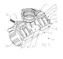
- Fig. 1 the inventive clamp clamp 1 is shown in the clamped state or in the assembled state.
- the pipe to which such a clamp clamp 1 is mounted is not shown.
- the clamp clamp 1 has a lower part 2, which corresponds to a cylindrical shell, which encloses more than half the circumference of the pipe, preferably 2/3 of the circumference.
- the assembly is simplified because the lower part 2 initially adheres to the pipeline without it must be kept by the fitter until the installation is completed.
- On the inner circumference of the lower part 2 is a structure 20 which avoids that the clamping tube clamp 1 moves.
- the structure 20 is formed on the inner periphery of the lower part 2 by webs which extend along the circumference to prevent axial displacement of the clamping tube clamp 1.
- the upper part 3 of the clamp clamp 1 has a saddle body 8, on which a connecting piece 5 is arranged.
- This can be used variably, that is, it can be designed as a tapping fitting and as a mere connecting piece or a combination is conceivable.
- the inventive clamp clamp 1 can be used for any applications.
- 3 tabs 4 are arranged on the upper part, which allow the joining of the lower part 2 and upper part 3.
- the tabs 4 are arranged in the guides 9 on the caliper body 8. Wherein the guides 9 extend as a groove or depression on the outer circumference of the caliper body 8.
- the width of the tabs 4 thus corresponds to the groove width of the guides 9, whereby the tabs 4 are axially guided. It is advantageous if the tabs 4, by support members 18 on the guides 9, the lifting is impossible. Thus, it is avoided that the locking elements 19 do not mesh with each other by the clamping ends 17 of the tabs 4 have no way to evade and are forced out.
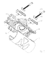
- guide elements which are preferably designed as T-nuts 21 and arranged on the inner circumference of the tabs 4, which made Fig. 2 is apparent.
- the T-nuts 21 run in the corresponding guide groove 22, preferably a T-groove on the caliper body 8.
- the tabs 4 on its outer circumference still circumferential ribs 23, which in Fig. 1 can be seen, which correspond to the grooves 24 in the support member 18 and thereby improve the leadership of the tabs 4 and stabilize.
- adjusting elements 10 are arranged, which are preferably designed as screws.
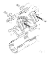
- washers 11 are arranged on the tabs 4 in the clamping region 12. These washers 11 have an inner radius 14, which in Fig. 5 It can be seen that corresponds to the outer radius 13 on the tabs 4 in the clamping portion 12 and thus causes a tightening and loosening of the tabs 4 without tilting the actuator 10 with the clamping portion 12 of the tabs 4. From the 3 and 4 is the clamping operation of the clamp clamp 1 clearly visible.
- Fig. 3 shows the clamp clamp 1 in not yet cocked or fully assembled position.
- Fig. 2 the grooves 7 on the inner circumference in the tabs 4 can be seen which serve to hook the tabs in the locking lugs 6 on the lower part and then sixteenzuspannen. Moreover, it is off Fig. 2 clearly seen that there is also a structure 20 on the inner circumference of the caliper body 8, wherein these webs are preferably arranged at 45 ° to the clamp clamp and so the rotation is prevented on the pipe.
Landscapes
- Engineering & Computer Science (AREA)
- General Engineering & Computer Science (AREA)
- Mechanical Engineering (AREA)
- Clamps And Clips (AREA)
Priority Applications (1)
| Application Number | Priority Date | Filing Date | Title |
|---|---|---|---|
| EP14168968.7A EP2947366B1 (fr) | 2014-05-20 | 2014-05-20 | Collier de serrage pour tuyaux |
Applications Claiming Priority (1)
| Application Number | Priority Date | Filing Date | Title |
|---|---|---|---|
| EP14168968.7A EP2947366B1 (fr) | 2014-05-20 | 2014-05-20 | Collier de serrage pour tuyaux |
Publications (2)
| Publication Number | Publication Date |
|---|---|
| EP2947366A1 true EP2947366A1 (fr) | 2015-11-25 |
| EP2947366B1 EP2947366B1 (fr) | 2017-05-10 |
Family
ID=50732032
Family Applications (1)
| Application Number | Title | Priority Date | Filing Date |
|---|---|---|---|
| EP14168968.7A Active EP2947366B1 (fr) | 2014-05-20 | 2014-05-20 | Collier de serrage pour tuyaux |
Country Status (1)
| Country | Link |
|---|---|
| EP (1) | EP2947366B1 (fr) |
Families Citing this family (1)
| Publication number | Priority date | Publication date | Assignee | Title |
|---|---|---|---|---|
| US20240230004A1 (en) * | 2023-01-06 | 2024-07-11 | Mueller International, Llc | Integral flexure tapping sleeve |
Citations (5)
| Publication number | Priority date | Publication date | Assignee | Title |
|---|---|---|---|---|
| US2239651A (en) * | 1938-11-21 | 1941-04-22 | M B Skinner Company | Service saddle |
| GB1324280A (en) * | 1969-12-23 | 1973-07-25 | Wavin Bv | Branch fitting for connecting a branch pipe to a main and a main provided with such a branch fitting |
| GB2018379A (en) * | 1978-04-10 | 1979-10-17 | Wavin Bv | Pipe branch piece |
| DE102005057662A1 (de) * | 2005-12-01 | 2007-06-14 | Viega Gmbh & Co. Kg | Rohrschelle, insbesondere Anbohrschelle |
| WO2012102968A2 (fr) * | 2011-01-28 | 2012-08-02 | Total Piping Solutions, Inc. | Joint d'étanchéité et manchon de coulée à portée étendue |
-
2014
- 2014-05-20 EP EP14168968.7A patent/EP2947366B1/fr active Active
Patent Citations (7)
| Publication number | Priority date | Publication date | Assignee | Title |
|---|---|---|---|---|
| US2239651A (en) * | 1938-11-21 | 1941-04-22 | M B Skinner Company | Service saddle |
| GB1324280A (en) * | 1969-12-23 | 1973-07-25 | Wavin Bv | Branch fitting for connecting a branch pipe to a main and a main provided with such a branch fitting |
| GB2018379A (en) * | 1978-04-10 | 1979-10-17 | Wavin Bv | Pipe branch piece |
| DE102005057662A1 (de) * | 2005-12-01 | 2007-06-14 | Viega Gmbh & Co. Kg | Rohrschelle, insbesondere Anbohrschelle |
| DE102005057662B4 (de) | 2005-12-01 | 2009-04-02 | Viega Gmbh & Co. Kg | Rohrschelle, insbesondere Anbohrschelle |
| WO2012102968A2 (fr) * | 2011-01-28 | 2012-08-02 | Total Piping Solutions, Inc. | Joint d'étanchéité et manchon de coulée à portée étendue |
| EP2668434A2 (fr) | 2011-01-28 | 2013-12-04 | Total Piping Solutions, Inc. | Joint d'étanchéité et manchon de coulée à portée étendue |
Also Published As
| Publication number | Publication date |
|---|---|
| EP2947366B1 (fr) | 2017-05-10 |
Similar Documents
| Publication | Publication Date | Title |
|---|---|---|
| EP3379129B1 (fr) | Raccord | |
| EP2268957B1 (fr) | Raccord tubulaire | |
| EP2674656A1 (fr) | Bride de fixation | |
| EP3017227B1 (fr) | Agencement de liaison de tube, système de conduites de fluide haute pression d'un moteur à combustion interne dualfuel, moteur à combustion interne dualfuel et utilisation d'un écrou de serrage | |
| EP3586018B1 (fr) | Dispositif de fixation et module de fixation | |
| DE102016105840B4 (de) | Membranventil | |
| EP2793334A2 (fr) | Dispositif de fixation de câble avec articulation intégrale | |
| DE102016116519A1 (de) | Federeinrichtung | |
| EP3680537B1 (fr) | Dispositif de raccordement pourvu d'articulation de pivotement | |
| EP3601865B1 (fr) | Raccord de tube | |
| EP2947366B1 (fr) | Collier de serrage pour tuyaux | |
| DE102015219420A1 (de) | Befestigungsvorrichtung zur Befestigung einer Sanitärarmatur | |
| DE202017001316U1 (de) | Mehrfachbefestigungsmittel mit zumindest einem Formschluss-Verbindungsabschnitt sowie Befestigungssystem mit einem solchen Mehrfachbefestigungsmittel | |
| DE102012103183A1 (de) | Teleskophalter und Klemmeinrichtung | |
| EP2775043B1 (fr) | Robinetterie | |
| DE3916278A1 (de) | Haltevorrichtung fuer ein schiebestueck mit tragelementen fuer rohre | |
| DE102020124264C5 (de) | System zur Handhabung und Fixierung von Rohrenden zur Herstellung einer Verbindung zwischen den Rohrenden, insbesondere zum Verbinden von Polyethylen-Rohren mittels einer Schweißmuffe | |
| DE102014210202B4 (de) | Fahrzeug mit Fahrzeugkupplung | |
| DE102010019326A1 (de) | Antennenhalter | |
| DE202014103768U1 (de) | Schnelle Einrastkonstruktion für verschiedene Rohrgrößen | |
| DE202014003430U1 (de) | Rohrelement für eine Trennwand | |
| EP3741466B1 (fr) | Dispositif de douche | |
| EP3584487A1 (fr) | Bride tubulaire pour tuyaux d'air de combustion ainsi que système de gaz d'échappement | |
| EP0620397B1 (fr) | Dispositif de support | |
| EP2252817B1 (fr) | Dispositif de surveillance de l'écoulement d'un gaz |
Legal Events
| Date | Code | Title | Description |
|---|---|---|---|
| PUAI | Public reference made under article 153(3) epc to a published international application that has entered the european phase |
Free format text: ORIGINAL CODE: 0009012 |
|
| AK | Designated contracting states |
Kind code of ref document: A1 Designated state(s): AL AT BE BG CH CY CZ DE DK EE ES FI FR GB GR HR HU IE IS IT LI LT LU LV MC MK MT NL NO PL PT RO RS SE SI SK SM TR |
|
| AX | Request for extension of the european patent |
Extension state: BA ME |
|
| 17P | Request for examination filed |
Effective date: 20160518 |
|
| RBV | Designated contracting states (corrected) |
Designated state(s): AL AT BE BG CH CY CZ DE DK EE ES FI FR GB GR HR HU IE IS IT LI LT LU LV MC MK MT NL NO PL PT RO RS SE SI SK SM TR |
|
| GRAP | Despatch of communication of intention to grant a patent |
Free format text: ORIGINAL CODE: EPIDOSNIGR1 |
|
| INTG | Intention to grant announced |
Effective date: 20170210 |
|
| GRAS | Grant fee paid |
Free format text: ORIGINAL CODE: EPIDOSNIGR3 |
|
| GRAA | (expected) grant |
Free format text: ORIGINAL CODE: 0009210 |
|
| AK | Designated contracting states |
Kind code of ref document: B1 Designated state(s): AL AT BE BG CH CY CZ DE DK EE ES FI FR GB GR HR HU IE IS IT LI LT LU LV MC MK MT NL NO PL PT RO RS SE SI SK SM TR |
|
| REG | Reference to a national code |
Ref country code: GB Ref legal event code: FG4D Free format text: NOT ENGLISH |
|
| REG | Reference to a national code |
Ref country code: AT Ref legal event code: REF Ref document number: 892721 Country of ref document: AT Kind code of ref document: T Effective date: 20170515 Ref country code: CH Ref legal event code: EP |
|
| REG | Reference to a national code |
Ref country code: IE Ref legal event code: FG4D Free format text: LANGUAGE OF EP DOCUMENT: GERMAN |
|
| REG | Reference to a national code |
Ref country code: DE Ref legal event code: R096 Ref document number: 502014003723 Country of ref document: DE |
|
| REG | Reference to a national code |
Ref country code: NL Ref legal event code: MP Effective date: 20170510 |
|
| REG | Reference to a national code |
Ref country code: LT Ref legal event code: MG4D |
|
| PG25 | Lapsed in a contracting state [announced via postgrant information from national office to epo] |
Ref country code: GR Free format text: LAPSE BECAUSE OF FAILURE TO SUBMIT A TRANSLATION OF THE DESCRIPTION OR TO PAY THE FEE WITHIN THE PRESCRIBED TIME-LIMIT Effective date: 20170811 Ref country code: ES Free format text: LAPSE BECAUSE OF FAILURE TO SUBMIT A TRANSLATION OF THE DESCRIPTION OR TO PAY THE FEE WITHIN THE PRESCRIBED TIME-LIMIT Effective date: 20170510 Ref country code: FI Free format text: LAPSE BECAUSE OF FAILURE TO SUBMIT A TRANSLATION OF THE DESCRIPTION OR TO PAY THE FEE WITHIN THE PRESCRIBED TIME-LIMIT Effective date: 20170510 Ref country code: LT Free format text: LAPSE BECAUSE OF FAILURE TO SUBMIT A TRANSLATION OF THE DESCRIPTION OR TO PAY THE FEE WITHIN THE PRESCRIBED TIME-LIMIT Effective date: 20170510 Ref country code: HR Free format text: LAPSE BECAUSE OF FAILURE TO SUBMIT A TRANSLATION OF THE DESCRIPTION OR TO PAY THE FEE WITHIN THE PRESCRIBED TIME-LIMIT Effective date: 20170510 Ref country code: NO Free format text: LAPSE BECAUSE OF FAILURE TO SUBMIT A TRANSLATION OF THE DESCRIPTION OR TO PAY THE FEE WITHIN THE PRESCRIBED TIME-LIMIT Effective date: 20170810 |
|
| PG25 | Lapsed in a contracting state [announced via postgrant information from national office to epo] |
Ref country code: PL Free format text: LAPSE BECAUSE OF FAILURE TO SUBMIT A TRANSLATION OF THE DESCRIPTION OR TO PAY THE FEE WITHIN THE PRESCRIBED TIME-LIMIT Effective date: 20170510 Ref country code: LV Free format text: LAPSE BECAUSE OF FAILURE TO SUBMIT A TRANSLATION OF THE DESCRIPTION OR TO PAY THE FEE WITHIN THE PRESCRIBED TIME-LIMIT Effective date: 20170510 Ref country code: SE Free format text: LAPSE BECAUSE OF FAILURE TO SUBMIT A TRANSLATION OF THE DESCRIPTION OR TO PAY THE FEE WITHIN THE PRESCRIBED TIME-LIMIT Effective date: 20170510 Ref country code: RS Free format text: LAPSE BECAUSE OF FAILURE TO SUBMIT A TRANSLATION OF THE DESCRIPTION OR TO PAY THE FEE WITHIN THE PRESCRIBED TIME-LIMIT Effective date: 20170510 Ref country code: BG Free format text: LAPSE BECAUSE OF FAILURE TO SUBMIT A TRANSLATION OF THE DESCRIPTION OR TO PAY THE FEE WITHIN THE PRESCRIBED TIME-LIMIT Effective date: 20170810 Ref country code: IS Free format text: LAPSE BECAUSE OF FAILURE TO SUBMIT A TRANSLATION OF THE DESCRIPTION OR TO PAY THE FEE WITHIN THE PRESCRIBED TIME-LIMIT Effective date: 20170910 Ref country code: NL Free format text: LAPSE BECAUSE OF FAILURE TO SUBMIT A TRANSLATION OF THE DESCRIPTION OR TO PAY THE FEE WITHIN THE PRESCRIBED TIME-LIMIT Effective date: 20170510 |
|
| REG | Reference to a national code |
Ref country code: CH Ref legal event code: PL |
|
| PG25 | Lapsed in a contracting state [announced via postgrant information from national office to epo] |
Ref country code: SK Free format text: LAPSE BECAUSE OF FAILURE TO SUBMIT A TRANSLATION OF THE DESCRIPTION OR TO PAY THE FEE WITHIN THE PRESCRIBED TIME-LIMIT Effective date: 20170510 Ref country code: CZ Free format text: LAPSE BECAUSE OF FAILURE TO SUBMIT A TRANSLATION OF THE DESCRIPTION OR TO PAY THE FEE WITHIN THE PRESCRIBED TIME-LIMIT Effective date: 20170510 Ref country code: RO Free format text: LAPSE BECAUSE OF FAILURE TO SUBMIT A TRANSLATION OF THE DESCRIPTION OR TO PAY THE FEE WITHIN THE PRESCRIBED TIME-LIMIT Effective date: 20170510 Ref country code: EE Free format text: LAPSE BECAUSE OF FAILURE TO SUBMIT A TRANSLATION OF THE DESCRIPTION OR TO PAY THE FEE WITHIN THE PRESCRIBED TIME-LIMIT Effective date: 20170510 Ref country code: DK Free format text: LAPSE BECAUSE OF FAILURE TO SUBMIT A TRANSLATION OF THE DESCRIPTION OR TO PAY THE FEE WITHIN THE PRESCRIBED TIME-LIMIT Effective date: 20170510 |
|
| REG | Reference to a national code |
Ref country code: DE Ref legal event code: R097 Ref document number: 502014003723 Country of ref document: DE |
|
| REG | Reference to a national code |
Ref country code: IE Ref legal event code: MM4A |
|
| PG25 | Lapsed in a contracting state [announced via postgrant information from national office to epo] |
Ref country code: LI Free format text: LAPSE BECAUSE OF NON-PAYMENT OF DUE FEES Effective date: 20170531 Ref country code: CH Free format text: LAPSE BECAUSE OF NON-PAYMENT OF DUE FEES Effective date: 20170531 Ref country code: SM Free format text: LAPSE BECAUSE OF FAILURE TO SUBMIT A TRANSLATION OF THE DESCRIPTION OR TO PAY THE FEE WITHIN THE PRESCRIBED TIME-LIMIT Effective date: 20170510 |
|
| PLBE | No opposition filed within time limit |
Free format text: ORIGINAL CODE: 0009261 |
|
| STAA | Information on the status of an ep patent application or granted ep patent |
Free format text: STATUS: NO OPPOSITION FILED WITHIN TIME LIMIT |
|
| PG25 | Lapsed in a contracting state [announced via postgrant information from national office to epo] |
Ref country code: LU Free format text: LAPSE BECAUSE OF NON-PAYMENT OF DUE FEES Effective date: 20170520 |
|
| 26N | No opposition filed |
Effective date: 20180213 |
|
| REG | Reference to a national code |
Ref country code: BE Ref legal event code: MM Effective date: 20170531 |
|
| PG25 | Lapsed in a contracting state [announced via postgrant information from national office to epo] |
Ref country code: IE Free format text: LAPSE BECAUSE OF NON-PAYMENT OF DUE FEES Effective date: 20170520 |
|
| REG | Reference to a national code |
Ref country code: FR Ref legal event code: ST Effective date: 20180404 |
|
| PG25 | Lapsed in a contracting state [announced via postgrant information from national office to epo] |
Ref country code: SI Free format text: LAPSE BECAUSE OF FAILURE TO SUBMIT A TRANSLATION OF THE DESCRIPTION OR TO PAY THE FEE WITHIN THE PRESCRIBED TIME-LIMIT Effective date: 20170510 |
|
| PG25 | Lapsed in a contracting state [announced via postgrant information from national office to epo] |
Ref country code: BE Free format text: LAPSE BECAUSE OF NON-PAYMENT OF DUE FEES Effective date: 20170531 Ref country code: FR Free format text: LAPSE BECAUSE OF NON-PAYMENT OF DUE FEES Effective date: 20170710 |
|
| PG25 | Lapsed in a contracting state [announced via postgrant information from national office to epo] |
Ref country code: MT Free format text: LAPSE BECAUSE OF FAILURE TO SUBMIT A TRANSLATION OF THE DESCRIPTION OR TO PAY THE FEE WITHIN THE PRESCRIBED TIME-LIMIT Effective date: 20170510 |
|
| PG25 | Lapsed in a contracting state [announced via postgrant information from national office to epo] |
Ref country code: MC Free format text: LAPSE BECAUSE OF FAILURE TO SUBMIT A TRANSLATION OF THE DESCRIPTION OR TO PAY THE FEE WITHIN THE PRESCRIBED TIME-LIMIT Effective date: 20170510 Ref country code: HU Free format text: LAPSE BECAUSE OF FAILURE TO SUBMIT A TRANSLATION OF THE DESCRIPTION OR TO PAY THE FEE WITHIN THE PRESCRIBED TIME-LIMIT; INVALID AB INITIO Effective date: 20140520 |
|
| PG25 | Lapsed in a contracting state [announced via postgrant information from national office to epo] |
Ref country code: CY Free format text: LAPSE BECAUSE OF FAILURE TO SUBMIT A TRANSLATION OF THE DESCRIPTION OR TO PAY THE FEE WITHIN THE PRESCRIBED TIME-LIMIT Effective date: 20170510 |
|
| PG25 | Lapsed in a contracting state [announced via postgrant information from national office to epo] |
Ref country code: MK Free format text: LAPSE BECAUSE OF FAILURE TO SUBMIT A TRANSLATION OF THE DESCRIPTION OR TO PAY THE FEE WITHIN THE PRESCRIBED TIME-LIMIT Effective date: 20170510 |
|
| PG25 | Lapsed in a contracting state [announced via postgrant information from national office to epo] |
Ref country code: TR Free format text: LAPSE BECAUSE OF FAILURE TO SUBMIT A TRANSLATION OF THE DESCRIPTION OR TO PAY THE FEE WITHIN THE PRESCRIBED TIME-LIMIT Effective date: 20170510 |
|
| PG25 | Lapsed in a contracting state [announced via postgrant information from national office to epo] |
Ref country code: PT Free format text: LAPSE BECAUSE OF FAILURE TO SUBMIT A TRANSLATION OF THE DESCRIPTION OR TO PAY THE FEE WITHIN THE PRESCRIBED TIME-LIMIT Effective date: 20170510 |
|
| PG25 | Lapsed in a contracting state [announced via postgrant information from national office to epo] |
Ref country code: AL Free format text: LAPSE BECAUSE OF FAILURE TO SUBMIT A TRANSLATION OF THE DESCRIPTION OR TO PAY THE FEE WITHIN THE PRESCRIBED TIME-LIMIT Effective date: 20170510 |
|
| P01 | Opt-out of the competence of the unified patent court (upc) registered |
Effective date: 20230529 |
|
| PGFP | Annual fee paid to national office [announced via postgrant information from national office to epo] |
Ref country code: DE Payment date: 20250521 Year of fee payment: 12 |
|
| PGFP | Annual fee paid to national office [announced via postgrant information from national office to epo] |
Ref country code: GB Payment date: 20250527 Year of fee payment: 12 |
|
| PGFP | Annual fee paid to national office [announced via postgrant information from national office to epo] |
Ref country code: IT Payment date: 20250527 Year of fee payment: 12 |
|
| PGFP | Annual fee paid to national office [announced via postgrant information from national office to epo] |
Ref country code: AT Payment date: 20250522 Year of fee payment: 12 |