EP2947452A1 - Zerstörungsfreie versickerungstiefenmessung unter verwendung von kapazitätsspektroskopie - Google Patents
Zerstörungsfreie versickerungstiefenmessung unter verwendung von kapazitätsspektroskopie Download PDFInfo
- Publication number
- EP2947452A1 EP2947452A1 EP15166121.2A EP15166121A EP2947452A1 EP 2947452 A1 EP2947452 A1 EP 2947452A1 EP 15166121 A EP15166121 A EP 15166121A EP 2947452 A1 EP2947452 A1 EP 2947452A1
- Authority
- EP
- European Patent Office
- Prior art keywords
- capacitance
- pdc cutter
- leached
- pdc
- cutter
- Prior art date
- Legal status (The legal status is an assumption and is not a legal conclusion. Google has not performed a legal analysis and makes no representation as to the accuracy of the status listed.)
- Withdrawn
Links
- 238000002386 leaching Methods 0.000 title claims description 106
- 238000005259 measurement Methods 0.000 title description 20
- 238000004611 spectroscopical analysis Methods 0.000 title 1
- 238000000034 method Methods 0.000 claims abstract description 115
- 239000000463 material Substances 0.000 claims abstract description 46
- 229910003460 diamond Inorganic materials 0.000 claims abstract description 38
- 239000010432 diamond Substances 0.000 claims abstract description 38
- 239000003054 catalyst Substances 0.000 claims abstract description 32
- 238000005520 cutting process Methods 0.000 claims description 90
- 238000011088 calibration curve Methods 0.000 claims description 48
- 230000008569 process Effects 0.000 claims description 20
- 238000013507 mapping Methods 0.000 claims description 16
- 239000006227 byproduct Substances 0.000 claims description 11
- 230000008878 coupling Effects 0.000 claims description 9
- 238000010168 coupling process Methods 0.000 claims description 9
- 238000005859 coupling reaction Methods 0.000 claims description 9
- 238000005498 polishing Methods 0.000 claims description 5
- 238000004140 cleaning Methods 0.000 claims description 3
- 239000004020 conductor Substances 0.000 description 43
- 239000011810 insulating material Substances 0.000 description 30
- 239000000758 substrate Substances 0.000 description 29
- 229910017052 cobalt Inorganic materials 0.000 description 25
- 239000010941 cobalt Substances 0.000 description 25
- GUTLYIVDDKVIGB-UHFFFAOYSA-N cobalt atom Chemical compound [Co] GUTLYIVDDKVIGB-UHFFFAOYSA-N 0.000 description 25
- 230000001066 destructive effect Effects 0.000 description 15
- RYGMFSIKBFXOCR-UHFFFAOYSA-N Copper Chemical compound [Cu] RYGMFSIKBFXOCR-UHFFFAOYSA-N 0.000 description 14
- 239000002245 particle Substances 0.000 description 10
- 239000000843 powder Substances 0.000 description 9
- UONOETXJSWQNOL-UHFFFAOYSA-N tungsten carbide Chemical compound [W+]#[C-] UONOETXJSWQNOL-UHFFFAOYSA-N 0.000 description 8
- XEEYBQQBJWHFJM-UHFFFAOYSA-N Iron Chemical compound [Fe] XEEYBQQBJWHFJM-UHFFFAOYSA-N 0.000 description 6
- PXHVJJICTQNCMI-UHFFFAOYSA-N Nickel Chemical compound [Ni] PXHVJJICTQNCMI-UHFFFAOYSA-N 0.000 description 6
- 230000008901 benefit Effects 0.000 description 4
- 239000011230 binding agent Substances 0.000 description 4
- 230000015572 biosynthetic process Effects 0.000 description 4
- 238000005245 sintering Methods 0.000 description 4
- 229910052782 aluminium Inorganic materials 0.000 description 3
- XAGFODPZIPBFFR-UHFFFAOYSA-N aluminium Chemical compound [Al] XAGFODPZIPBFFR-UHFFFAOYSA-N 0.000 description 3
- 230000007423 decrease Effects 0.000 description 3
- 238000004146 energy storage Methods 0.000 description 3
- 239000011888 foil Substances 0.000 description 3
- 229910052742 iron Inorganic materials 0.000 description 3
- 229910052751 metal Inorganic materials 0.000 description 3
- 239000002184 metal Substances 0.000 description 3
- 239000000203 mixture Substances 0.000 description 3
- 238000012986 modification Methods 0.000 description 3
- 230000004048 modification Effects 0.000 description 3
- 229910052759 nickel Inorganic materials 0.000 description 3
- 239000002904 solvent Substances 0.000 description 3
- 238000003786 synthesis reaction Methods 0.000 description 3
- GJNGXPDXRVXSEH-UHFFFAOYSA-N 4-chlorobenzonitrile Chemical compound ClC1=CC=C(C#N)C=C1 GJNGXPDXRVXSEH-UHFFFAOYSA-N 0.000 description 2
- VYZAMTAEIAYCRO-UHFFFAOYSA-N Chromium Chemical compound [Cr] VYZAMTAEIAYCRO-UHFFFAOYSA-N 0.000 description 2
- 239000000956 alloy Substances 0.000 description 2
- 229910045601 alloy Inorganic materials 0.000 description 2
- 239000003990 capacitor Substances 0.000 description 2
- 230000008859 change Effects 0.000 description 2
- 229910052802 copper Inorganic materials 0.000 description 2
- 239000010949 copper Substances 0.000 description 2
- 238000009760 electrical discharge machining Methods 0.000 description 2
- 238000004519 manufacturing process Methods 0.000 description 2
- 150000002739 metals Chemical class 0.000 description 2
- 239000004033 plastic Substances 0.000 description 2
- 230000000717 retained effect Effects 0.000 description 2
- 239000011435 rock Substances 0.000 description 2
- 230000003068 static effect Effects 0.000 description 2
- 239000000126 substance Substances 0.000 description 2
- 229910052582 BN Inorganic materials 0.000 description 1
- PZNSFCLAULLKQX-UHFFFAOYSA-N Boron nitride Chemical compound N#B PZNSFCLAULLKQX-UHFFFAOYSA-N 0.000 description 1
- 239000002253 acid Substances 0.000 description 1
- 230000004888 barrier function Effects 0.000 description 1
- 239000011203 carbon fibre reinforced carbon Substances 0.000 description 1
- 230000015556 catabolic process Effects 0.000 description 1
- 238000006243 chemical reaction Methods 0.000 description 1
- 229910052804 chromium Inorganic materials 0.000 description 1
- 239000011651 chromium Substances 0.000 description 1
- 239000000470 constituent Substances 0.000 description 1
- 238000010276 construction Methods 0.000 description 1
- 238000006731 degradation reaction Methods 0.000 description 1
- 230000001419 dependent effect Effects 0.000 description 1
- 230000002999 depolarising effect Effects 0.000 description 1
- 238000009792 diffusion process Methods 0.000 description 1
- 238000005553 drilling Methods 0.000 description 1
- 230000000694 effects Effects 0.000 description 1
- 238000005755 formation reaction Methods 0.000 description 1
- 239000011521 glass Substances 0.000 description 1
- 238000005087 graphitization Methods 0.000 description 1
- 238000000227 grinding Methods 0.000 description 1
- 238000002847 impedance measurement Methods 0.000 description 1
- 238000003754 machining Methods 0.000 description 1
- WPBNNNQJVZRUHP-UHFFFAOYSA-L manganese(2+);methyl n-[[2-(methoxycarbonylcarbamothioylamino)phenyl]carbamothioyl]carbamate;n-[2-(sulfidocarbothioylamino)ethyl]carbamodithioate Chemical compound [Mn+2].[S-]C(=S)NCCNC([S-])=S.COC(=O)NC(=S)NC1=CC=CC=C1NC(=S)NC(=O)OC WPBNNNQJVZRUHP-UHFFFAOYSA-L 0.000 description 1
- 239000000155 melt Substances 0.000 description 1
- 239000012811 non-conductive material Substances 0.000 description 1
- 239000004417 polycarbonate Substances 0.000 description 1
- 229920000515 polycarbonate Polymers 0.000 description 1
- 238000005381 potential energy Methods 0.000 description 1
- 239000012266 salt solution Substances 0.000 description 1
- 238000000926 separation method Methods 0.000 description 1
- 230000002194 synthesizing effect Effects 0.000 description 1
- 229910052715 tantalum Inorganic materials 0.000 description 1
- GUVRBAGPIYLISA-UHFFFAOYSA-N tantalum atom Chemical compound [Ta] GUVRBAGPIYLISA-UHFFFAOYSA-N 0.000 description 1
- 238000012360 testing method Methods 0.000 description 1
Images


Classifications
-
- G—PHYSICS
- G01—MEASURING; TESTING
- G01N—INVESTIGATING OR ANALYSING MATERIALS BY DETERMINING THEIR CHEMICAL OR PHYSICAL PROPERTIES
- G01N27/00—Investigating or analysing materials by the use of electric, electrochemical, or magnetic means
- G01N27/02—Investigating or analysing materials by the use of electric, electrochemical, or magnetic means by investigating impedance
- G01N27/22—Investigating or analysing materials by the use of electric, electrochemical, or magnetic means by investigating impedance by investigating capacitance
- G01N27/24—Investigating the presence of flaws
-
- G—PHYSICS
- G01—MEASURING; TESTING
- G01N—INVESTIGATING OR ANALYSING MATERIALS BY DETERMINING THEIR CHEMICAL OR PHYSICAL PROPERTIES
- G01N33/00—Investigating or analysing materials by specific methods not covered by groups G01N1/00 - G01N31/00
- G01N33/40—Grinding-materials
Definitions
- the present invention relates generally to a method and apparatus for measuring characteristics of one or more regions within an ultra-hard polycrystalline structure; and more particularly, to a non-destructive method and apparatus for measuring the leaching depth within the ultra-hard polycrystalline structure and/or characterizing at least a portion of the ultra-hard polycrystalline structure, such as the ones used in forming polycrystalline diamond compact (“PDC”) cutters, using at least capacitance measurements.
- PDC polycrystalline diamond compact
- PDC Polycrystalline diamond compacts
- HPHT high pressure and high temperature
- the PDC can be formed by sintering individual diamond particles together under the high pressure and high temperature (“HPHT") conditions referred to as the "diamond stable region,” which is typically above forty kilobars and between 1,200 degrees Celsius and 2,000 degrees Celsius, in the presence of a catalyst/solvent which promotes diamond-diamond bonding.
- catalyst/solvents for sintered diamond compacts are cobalt, nickel, iron, and other Group VIII metals.
- PDCs usually have a diamond content greater than seventy percent by volume, with about eighty percent to about ninety-eight percent being typical.
- An unbacked PDC can be mechanically bonded to a tool (not shown), according to one example.
- the PDC is bonded to a substrate, thereby forming a PDC cutter, which is typically insertable within a downhole tool (not shown), such as a drill bit or a reamer.
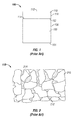
- FIG 1 shows a side view of a PDC cutter 100 having a polycrystalline diamond (“PCD”) cutting table 110, or compact, in accordance with the prior art.
- PCD polycrystalline diamond
- the PDC cutter 100 typically includes the PCD cutting table 110 and a substrate 150 that is coupled to the PCD cutting table 110.
- the PCD cutting table 110 is about one hundred thousandths of an inch (2.5 millimeters) thick; however, the thickness is variable depending upon the application in which the PCD cutting table 110 is to be used.
- the substrate 150 includes a top surface 152, a bottom surface 154, and a substrate outer wall 156 that extends from the circumference of the top surface 152 to the circumference of the bottom surface 154.
- the PCD cutting table 110 includes a cutting surface 112, an opposing surface 114, and a PCD cutting table outer wall 116 that extends from the circumference of the cutting surface 112 to the circumference of the opposing surface 114.
- the opposing surface 114 of the PCD cutting table 110 is coupled to the top surface 152 of the substrate 150.
- the PCD cutting table 110 is coupled to the substrate 150 using a high pressure and high temperature (“HPHT") press.
- HPHT high pressure and high temperature
- other methods known to people having ordinary skill in the art can be used to couple the PCD cutting table 110 to the substrate 150.
- the cutting surface 112 of the PCD cutting table 110 is substantially parallel to the substrate's bottom surface 154.
- the PDC cutter 100 has been illustrated as having a right circular cylindrical shape; however, the PDC cutter 100 is shaped into other geometric or non-geometric shapes in other exemplary embodiments.
- the opposing surface 114 and the top surface 152 are substantially planar; however, the opposing surface 114 and the top surface 152 are non-planar in other exemplary embodiments.
- a bevel (not shown) is formed around at least the circumference of the cutting surface 112.
- the PDC cutter 100 is formed by independently forming the PCD cutting table 110 and the substrate 150, and thereafter bonding the PCD cutting table 110 to the substrate 150.
- the substrate 150 is initially formed and the PCD cutting table 110 is subsequently formed on the top surface 152 of the substrate 150 by placing polycrystalline diamond powder onto the top surface 152 and subjecting the polycrystalline diamond powder and the substrate 150 to a high temperature and high pressure process.
- the substrate 150 and the PCD cutting table 110 are formed and bonded together at about the same time.
- the PCD cutting table 110 is formed and bonded to the substrate 150 by subjecting a layer of diamond powder and a mixture of tungsten carbide and cobalt powders to HPHT conditions.
- the cobalt is typically mixed with tungsten carbide and positioned where the substrate 150 is to be formed.
- the diamond powder is placed on top of the cobalt and tungsten carbide mixture and positioned where the PCD cutting table 110 is to be formed.
- the entire powder mixture is then subjected to HPHT conditions so that the cobalt melts and facilitates the cementing, or binding, of the tungsten carbide to form the substrate 150.
- the melted cobalt also diffuses, or infiltrates, into the diamond powder and acts as a catalyst for synthesizing diamond bonds and forming the PCD cutting table 110.
- the cobalt acts as both a binder for cementing the tungsten carbide and as a catalyst/solvent for sintering the diamond powder to form diamond-diamond bonds.
- the cobalt also facilitates in forming strong bonds between the PCD cutting table 110 and the cemented tungsten carbide substrate 150.
- Cobalt has been a preferred constituent of the PDC manufacturing process.
- Traditional PDC manufacturing processes use cobalt as the binder material for forming the substrate 150 and also as the catalyst material for diamond synthesis because of the large body of knowledge related to using cobalt in these processes.
- the synergy between the large bodies of knowledge and the needs of the process have led to using cobalt as both the binder material and the catalyst material.
- alternative metals such as iron, nickel, chromium, manganese, and tantalum, and other suitable materials, can be used as a catalyst for diamond synthesis.
- cobalt or some other material such as nickel chrome or iron, is typically used as the binder material for cementing the tungsten carbide to form the substrate 150.
- some materials, such as tungsten carbide and cobalt have been provided as examples, other materials known to people having ordinary skill in the art can be used to form the substrate 150, the PCD cutting table 110, and the bonds between the substrate 150 and the PCD cutting table 110.
- FIG 2 is a schematic microstructural view of the PCD cutting table 110 of Figure 1 in accordance with the prior art.
- the PCD cutting table 110 has diamond particles 210 bonded to other diamond particles 210, one or more interstitial spaces 212 formed between the diamond particles 210, and cobalt 214, or some other catalyst, deposited within one or more of the interstitial spaces 212.
- the interstitial spaces 212, or voids are formed between the carbon-carbon bonds and are located between the diamond particles 210.
- the diffusion of cobalt 214 into the diamond powder results in cobalt 214 being deposited within these interstitial spaces 212 that are formed within the PCD cutting table 110 during the sintering process.
- the PCD cutting table 110 is known to wear quickly when the temperature reaches a critical temperature.
- This critical temperature is about 750 degrees Celsius and is reached when the PCD cutting table 110 is cutting rock formations or other known materials.
- the high rate of wear is believed to be caused by the differences in the thermal expansion rate between the diamond particles 210 and the cobalt 214 and also by the chemical reaction, or graphitization, that occurs between cobalt 214 and the diamond particles 210.
- the coefficient of thermal expansion for the diamond particles 210 is about 1.0 x 10 -6 millimeters -1 x Kelvin -1 ("mm -1 K -1 "), while the coefficient of thermal expansion for the cobalt 214 is about 13.0 x 10 -6 mm -1 K -1 .
- the cobalt 214 expands much faster than the diamond particles 210 at temperatures above this critical temperature, thereby making the bonds between the diamond particles 210 unstable.
- the PCD cutting table 110 becomes thermally degraded at temperatures above about 750 degrees Celsius and its cutting efficiency deteriorates significantly.
- Efforts have been made to slow the wear of the PCD cutting table 110 at these high temperatures. These efforts include performing a leaching process on the PCD cutting table 110, which removes some of the cobalt 214 from the interstitial spaces 212. These leaching processes, which includes, but is not limited to, an acid leaching process and/or an electrolytic leaching process, is known to persons having ordinary skill in the art and is not described herein for the sake of brevity. By removing some of the cobalt 214, or catalyst, from the PCD cutting table 110, the thermal degradation of the PCD structure is reduced.
- FIG 3 shows a cross-section view of a leached PDC cutter 300 having a PCD cutting table 310 that has been at least partially leached in accordance with the prior art.
- the PDC cutter 300 includes the PCD cutting table 310 coupled to a substrate 350.
- the substrate 350 is similar to substrate 150 ( Figure 1 ) and is not described again for the sake of brevity.
- the PCD cutting table 310 is similar to the PCD cutting table 110 ( Figure 1 ), but includes a leached layer 354 and an unleached layer 356.
- the leached layer 354 extends from the cutting surface 312, which is similar to the cutting surface 112 ( Figure 1 ), towards an opposing surface 314, which is similar to the opposing surface 114 ( Figure 1 ).
- the leached layer 354 has been leached to a desired depth 353.
- one or more by-product materials 398 are formed and deposited within some of the interstitial spaces 212 ( Figure 2 ) in the leached layer 354.
- the unleached layer 356 is similar to the PCD cutting table 150 ( Figure 1 ) and extends from the end of the leached layer 354 to the opposing surface 314.
- the cobalt 214 ( Figure 2 ) remains within the interstitial spaces 212 ( Figure 2 ).
- a boundary line 355 is formed between the leached layer 354 and the unleached layer 356 and is depicted as being substantially linear, the boundary line 355 can be non-linear.
- the leached PDC cutters 300 are leached to different desired depths 353 and how deep the cutter 300 has been leached has an effect on the performance of the cutter 300.
- the leached depth 353 of the cutter 300 is measured, or determined, by cutting the cutter 300 vertically in half and then subsequently polishing the cutter 300.
- the leached depth 353 is visually measured under a microscope or similar magnifying device. This process is rather tedious and cumbersome as it involves cutting the cutter 300, such as by electrical discharge machining ("EDM”), mounting, grinding, and polishing the cutter 300, and performing an analysis under a microscope. Additionally, this process destroys the cutter 300 from subsequently being used.
- EDM electrical discharge machining
- the leached depth 353 that is determined in this manner is assumed to be the same leached depth in other cutters that were leached in the same batch.
- a method of characterizing a quality of a polycrystalline diamond compact (PDC) cutter includes obtaining a PDC cutter that includes a leached layer and an unleached layer. The unleached layer is positioned adjacent to the leached layer, and the leached layer has at least a portion of a catalyst material removed from therein. The method further includes measuring capacitance values of the PDC cutter at multiple frequencies of an electrical signal provided to the PDC cutter by a capacitance measuring device to measure the capacitance values of the PDC cutter. The method also includes characterizing a quality of the PDC cutter based on a lowest capacitance value from among the capacitance values. Each capacitance value of the capacitance values is measured at a respective frequency of the multiple frequencies of the electrical signal.
- a method of characterizing a quality of a polycrystalline structure includes obtaining a leached component comprising a polycrystalline structure.
- the polycrystalline structure comprises a leached layer and an unleached layer.
- the unleached layer is positioned adjacent to the leached layer.
- the leached layer has at least a portion of a catalyst material removed from therein.
- the method further includes measuring capacitance values of the leached component at multiple frequencies of an electrical signal.
- the electrical signal is provided to the leached component by a capacitance measuring device to measure capacitance of the leached component.
- the method also includes characterizing a quality of the leached component based on a lowest capacitance value from among the capacitance values. Each capacitance value of the capacitance values is measured at a respective frequency of the multiple frequencies of the electrical signal.
- a system for measuring capacitance of a polycrystalline diamond compact (PDC) cutter includes a capacitance measuring device that includes a first terminal and a second terminal.
- the system further includes a PDC cutter that has a leached layer and an unleached layer adjacent to the leached layer.
- the leached layer has at least a portion of a catalyst material removed from therein.
- the system also includes a first wire electrically coupling the first terminal to a first surface of the PDC cutter.
- the system further includes a second wire electrically coupling the second terminal to a second surface of the PDC cutter.
- the first surface and the second surface are on opposite sides of the leached layer.
- the second surface is a surface of the leached layer.
- the capacitance measuring device provides an electrical signal to the PDC cutter to measure capacitance values of the PDC cutter.
- the capacitance measuring device measures the capacitance values of the PDC cutter at multiple frequencies of the electrical signal.
- the present invention is directed to a non-destructive method and apparatus for measuring the leaching depth within an ultra-hard polycrystalline structure and/or characterizing at least a portion of the ultra-hard polycrystalline structure, such as the ones used in forming polycrystalline diamond compact ("PDC") cutters, using at least capacitance measurements.
- PDC polycrystalline diamond compact
- the description of exemplary embodiments is provided below in conjunction with a PDC cutter, alternate embodiments of the invention may be applicable to other types of polycrystalline structures including, but not limited to, PCBN cutters.
- one or more portions of the methods described below are implemented using an electronic measuring device.
- the capacitance is measured using a capacitance measuring device.
- FIG. 4 is a schematic view of a capacitance measuring system 400 in accordance to one exemplary embodiment of the present invention.
- the capacitance measuring system 400 includes a capacitance measuring device 410, the leached PDC cutter 300, a first wire 430, and a second wire 440.
- a capacitance measuring device 410 the leached PDC cutter 300
- a first wire 430 the leached PDC cutter 300
- a second wire 440 second wire 440.
- additional components are included in other exemplary embodiments.
- the description provided below has been provided with respect to the leached PDC cutter 300, a different component, such as the PCD cutting table 310 alone or other component that includes another type of leached polycrystalline structure, is used in lieu of the leached PDC cutter 300.
- leached PDC cutter 300 a different component, such as a chemically cleaned leached PDC cutter (not shown), is used in lieu of the leached PDC cutter 300.
- the chemically cleaned leached PDC cutter has had at least a portion of the by-product materials 398 ( Figure 3 ) removed by using one or more processes described in related application entitled, "Method To Improve The Performance Of A Leached Cutter", which has been mentioned above and incorporated by reference herein.
- the leached PDC cutter 300 has been previously described with respect to Figure 3 and is not repeated again herein for the sake of brevity.
- the capacitance measuring device 410 is a device that measures the capacitance of an energy storage device, which is the leached PDC cutter 300 in the instant exemplary embodiment. Capacitance is a measure of the amount of electric potential energy stored, or separated, for a given electric potential.
- a common form of energy storage device is a parallel-plate capacitor.
- the leached PDC cutter 300 is an example of the parallel-plate capacitor.
- the capacitance of the energy storage device is typically measured in farads, or nanofarads.
- the capacitance measuring device 410 is a multi-meter; however, other capacitance measuring devices known to people having ordinary skill in the art are used in one or more alternative exemplary embodiments.
- the multi-meter 410 includes a positionable dial 412, a plurality of measurement settings 414, a display 416, a positive terminal 418, and a negative terminal 419.
- the positionable dial 412 is rotatable in a clockwise and/or counterclockwise manner and is set to one of several available measurement settings 414.
- the positionable dial 412 is set to a nanofaraday setting 415 so that the multi-meter 410 measures capacitance values.
- the display 416 is fabricated using polycarbonate, glass, plastic, or other known suitable material and communicates a measurement value, such as a capacitance value, to a user (not shown) of the multi-meter 410.
- the positive terminal 418 is electrically coupled to one end of the first wire 430, while the negative terminal 419 is electrically coupled to one end of the second wire 440.
- the first wire 430 is fabricated using a copper wire or some other suitable conducting material or alloy known to people having ordinary skill in the art.
- the first wire 430 also includes a non-conducting sheath (not shown) that surrounds the copper wire and extends from about one end of the copper wire to an opposing end of the cooper wire. The two ends of the copper wire are exposed and are not surrounded by the non-conducting sheath.
- an insulating material also surrounds the copper wire and is disposed between the copper wire and the non-conducting sheath. The insulating material extends from about one end of the non-conducting sheath to about an opposing end of the non-conducting sheath.
- first wire 430 is electrically coupled to the positive terminal 418, while the opposing end of the first wire 430 is electrically coupled to the cutting surface 312 of the leached PDC cutter 300.
- the opposing end of the first wire 430 is electrically coupled to the cutting surface 312 in one of several methods.
- the first wire 430 is electrically coupled to the cutting surface 312 using one or more fastening devices (not shown), such as a clamp, or using an equipment (not shown) that supplies a force to retain the first wire 430 in electrical contact with the cutting surface 312.
- a clamp (not shown) is coupled to the opposing end of the first wire 430 and a conducting component (not shown), such as aluminum foil, is coupled to, or placed in contact with, the cutting surface 312.
- the clamp is electrically coupled to the conducting component, thereby electrically coupling the first wire 430 to the cutting surface 312. Additional methods for coupling the first wire 430 to the cutting surface 312 can be used in other exemplary embodiments.
- the second wire 440 is fabricated using a copper wire or some other suitable conducting material or alloy known to people having ordinary skill in the art.
- the second wire 440 also includes a non-conducting sheath (not shown) that surrounds the copper wire and extends from about one end of the copper wire to an opposing end of the cooper wire. The two ends of the copper wire are exposed and are not surrounded by the non-conducting sheath.
- an insulating material also surrounds the copper wire and is disposed between the copper wire and the non-conducting sheath. The insulating material extends from about one end of the non-conducting sheath to an opposing end of the non-conducting sheath.
- one end of the second wire 440 is electrically coupled to the negative terminal 419, while the opposing end of the second wire 440 is electrically coupled to a bottom surface 454, which is similar to the bottom surface 154 ( Figure 1 ), of the leached PDC cutter 300.
- the second wire 440 is electrically coupled to the bottom surface 454 in a similar manner as the first wire 430 is electrically coupled to the cutting surface 312.
- a circuit 405 is completed using the multi-meter 410, the first wire 430, the leached PDC cutter 300, and the second wire 440.
- the current is able to flow from the positive terminal 418 of the multi-meter 410 to the cutting surface 312 of the leached PDC cutter 300 through the first wire 430.
- the current then flows through the leached PDC cutter 300 to the bottom surface 454 of the leached PDC cutter 300.
- the multi-meter 410 is turned on, a voltage differential exists between the cutting surface 312 and the bottom surface 454.
- the current then flows from the bottom surface 454 to the negative terminal 419 of the multi-meter 410 through the second wire 440.
- the capacitance measurement of the leached PDC cutter 300 is determined when the value displayed on the display 416 reaches a peak value or remains constant for a period of time.
- FIG. 5 is a schematic view of a capacitance measuring system 500 in accordance to another exemplary embodiment of the present invention.
- the capacitance measuring system 500 includes the capacitance measuring device 410, the leached PDC cutter 300, the first wire 430, the second wire 440, a first conducting material 510, a second conducting material 520, a first insulating material 530, a second insulating material 540, and an Arbor Press 550.
- certain components have been enumerated as being included in the capacitance measuring system 500, additional components are included in other exemplary embodiments.
- the first conducting material 510 and the second conducting material 520 are similar to one another in certain exemplary embodiments, but are different in other exemplary embodiments.
- the conducting materials 510, 520 are fabricated using aluminum foil; however, other suitable conducting materials can be used.
- the first conducting material 510 is positioned adjacently above and in contact with the cutting surface 312.
- the second conducting material 520 is positioned adjacently below and in contact with the bottom surface 454.
- the first conducting material 510 and the second conducting material 520 provide an area to which the first wire 430 and the second wire 440, respectively, make electrical contact. Additionally, the first conducting material 510 and the second conducting material 520 assist in minimizing contact resistance with the cutting surface 312 and the bottom surface 454, respectively, which is discussed in further detail below.
- the first conducting material 510 and the second conducting material 520 are the same shape and size; while in other exemplary embodiments, one of the conducting materials 510, 520 is a different shape and/or size than the other conducting material 510, 520.
- the first insulating material 530 and the second insulating material 540 are similar to one another in certain exemplary embodiments, but are different in other exemplary embodiments.
- the insulating materials 530, 540 are fabricated using paper; however, other suitable insulating materials, such as rubber, can be used.
- the first insulating material 530 is positioned adjacently above and in contact with the first conducting material 510.
- the second insulating material 540 is positioned adjacently below and in contact with the second conducting material 520.
- the first insulating material 530 and the second insulating material 540 provide a barrier to direct current flow only through a circuit 505, which is discussed in further detail below.
- the first insulating material 530 and the second insulating material 540 are the same shape and size; while in other exemplary embodiments, one of the insulating materials 530, 540 is a different shape and/or size than the other insulating material 530, 540. Additionally, in certain exemplary embodiments, the insulating materials 530, 540 is larger in size than its corresponding conducting material 510, 520. However, one or more of the insulating materials 530, 540 is either larger or smaller than its corresponding conducting material 510, 520 in alternative exemplary embodiments.
- the Arbor Press 550 includes an upper plate 552 and a base plate 554.
- the upper plate 552 is positioned above the base plate 554 and is movable towards the base plate 554.
- the base plate 554 is movable towards the upper plate 552.
- the first insulating material 530, the first conducting material 510, the leached PDC cutter 300, the second conducting material 520, and the second insulating material 540 are positioned between the upper plate 552 and the base plate 554 such that the second insulating material 540 is positioned adjacently above and in contact with the base plate 554.
- the upper plate 552 is moved towards the base plate 554 until the upper plate 552 applies a downward load 553 onto the cutting surface 312 of the leached PDC cutter 300.
- the base plate 554 also applies an upward load 555 onto the bottom surface 454 of the leached PDC cutter 300.
- the upward load 555 is applied, the second conducting material 520 is deformed and adapted to the rough and very stiff bottom surface 454, thereby minimizing contact resistance between the second conducting material 520 and the bottom surface 454 and greatly improving the capacitance measurement consistency.
- the downward load 553 is equal to the upward load 555.
- the downward load 553 and the upward load 555 is about one hundred pounds; however, these loads 553, 555 range from about two pounds to about a critical load.
- the critical load is a load at which the leached PDC cutter 300 is damaged when applied thereto.
- the second insulating material 540 is positioned on the base plate 554, the second conducting material 520 is positioned on the second insulating material 540, the leached PDC cutter 300 is positioned on the second conducting material 520, the first conducting material 510 is positioned on the leached PDC cutter 300, and the first insulating material 530 is positioned on the first conducting material 510.
- the upper plate 552 is moved towards the first insulating material 530 until the downward load 553 is applied onto the leached PDC cutter 300.
- one or more components such as the first insulating material 530 and the first conducting material 510, are coupled to the upper plate 552 prior to the upper plate 552 being moved towards the base plate 554.
- an Arbor Press 550 is used in the capacitance measuring system 500, other equipment capable of delivering equal and opposite loads to each of the cutting surface 312 and the bottom surface 454 of the leached PDC cutter 300 can be used in other exemplary embodiments.
- One end of the first wire 430 is electrically coupled to the positive terminal 418 of the multi-meter 410, while the opposing end of the first wire 430 is electrically coupled to the first conducting material 510, which thereby becomes electrically coupled to the cutting surface 312 of the leached PDC cutter 300.
- a clamp 590 is coupled to the opposing end of the first wire 430 which couples the first wire 430 to the first conducting material 510.
- One end of the second wire 440 is electrically coupled to the negative terminal 419 of the multi-meter 410, while the opposing end of the second wire 440 is electrically coupled to the second conducting material 520, which thereby becomes electrically coupled to the bottom surface 454 of the leached PDC cutter 300.
- a clamp (not shown), similar to clamp 590, is coupled to the opposing end of the second wire 440, which couples the second wire 440 to the second conducting material 520.
- the circuit 505 is completed using the multi-meter 410, the first wire 430, the first conducting material 510, the leached PDC cutter 300, the second conducting material 520, and the second wire 440.
- the current is able to flow from the positive terminal 418 of the multi-meter 410 to the cutting surface 312 of the leached PDC cutter 300 through the first wire 430 and the first conducting material 510.
- the current then flows through the leached PDC cutter 300 to the bottom surface 454 of the leached PDC cutter 300.
- the multi-meter 410 When the multi-meter 410 is turned on, a voltage differential exists between the cutting surface 312 and the bottom surface 454. The current then flows from the bottom surface 454 to the negative terminal 419 of the multi-meter 410 through the second conducting material 520 and the second wire 440. The first insulating material 530 and the second insulating material 540 prevent the current from flowing into the Arbor Press 550.
- the capacitance measurement of the leached PDC cutter 300 is determined when the value displayed on the display 416 reaches a peak value or remains constant for a period of time.
- FIG. 6 is a flowchart depicting a non-destructive leaching depth estimation method 600 in accordance with an exemplary embodiment of the present invention.
- Figure 6 shows a series of steps depicted in a certain order, the order of one or more steps can be rearranged, combined into fewer steps, and/or separated into more steps than that shown in other exemplary embodiments.
- the non-destructive leaching depth estimation method 600 begins at step 610.
- the non-destructive leaching depth estimation method 600 proceeds to step 620.
- a calibration curve is obtained. The calibration curve can be generated from tests or acquired from elsewhere.
- FIG 7 is a graphical chart 700 depicting the calibration curve 705 that shows a relationship between capacitance 710 and actual leaching depth 720 for a plurality of leached components 300 ( Figure 3 ) in accordance with an exemplary embodiment of the present invention.
- one or more of the leached components 300 have a different actual leaching depth 720 than at least one other leached component 300 ( Figure 3 ).
- the leached component 300 is the leached PDC cutter 300 ( Figure 3 ) according to some exemplary embodiments; however, the leached component 300 can be only the PCD cutting table 310 ( Figure 3 ) or some other component that has a polycrystalline structure that has had at least some of the catalyst material removed from therein.
- the leached component 300 can be the chemically cleaned leached PDC cutter mentioned above.
- the calibration curve 705 is generated by obtaining two or more leached components 300 ( Figure 3 ).
- the calibration curve 705 becomes more precise as more leached components 300 ( Figure 3 ) are used in generating the calibration curve 705.
- the capacitance data points 730 are obtained by measuring the capacitance 710 of each leached component 300 ( Figure 3 ).
- a plurality of capacitance data points 730 are obtained for each leached component 300 ( Figure 3 ).
- the capacitance 710 is measured five times for each leached component 300 ( Figure 3 ).
- Obtaining a plurality of capacitance data points 730 for each leached component 300 ( Figure 3 ) improves the statistical significance of the capacitance data points 730 being collected.
- the leached component 300 ( Figure 3 ) is depolarized after each measurement for capacitance 710, before each measurement for capacitance 710, or before and after each measurement for capacitance 710.
- the leached component 300 is depolarized in one or a combination of different manners, such as grounding the leached component 300 ( Figure 3 ), wrapping the leached component 300 ( Figure 3 ) in aluminum foil or similar type material, heat treating the leached component 300 ( Figure 3 ), dropping the leached component 300 ( Figure 3 ) in a salt solution, or waiting to discharge the leached component 300 ( Figure 3 ).
- the leached component 300 ( Figure 3 ) is discharged by waiting about twenty-four hours, but the waiting time is greater or less in other exemplary embodiments. Depolarizing an object is known to people having ordinary skill in the art.
- the actual leaching depth 720 for each leached component 300 is determined.
- the actual leaching depth 720 for a leached component 300 is determined by cutting the leached component 300 ( Figure 3 ), polishing the cut edge of the leached component 300 ( Figure 3 ), and visually measuring the actual leaching depth 720 under a magnifying device (not shown), such as a microscope.
- Each capacitance data point 730 is plotted on the graphical chart 700, where the actual leaching depth 720 is plotted versus the capacitance 710 that is measured.
- the calibration curve 705 is determined pursuant to methods known to people having ordinary skill in the art. For example, the calibration curve 705 is generated by using the average capacitance 711 of each leached component 300, the median capacitance 712 of each leached component, or by calculating the best fit curve.
- the best fit curve can be formed with a ninety-five percent confidence level, but this confidence level can range from about sixty percent to almost about one hundred percent, for example, 99.99 percent.
- the calibration curve 705 correlates the measured capacitance 710, which can be measured in nanofarads, with the actual leaching depth 720, which can be measured in microns. Although a few methods for generating the calibration curve 705 have been described, other methods, either destructive or non-destructive, can be used to generate the calibration curve 705.
- the actual leaching depth 720 is directly related to the capacitance 710.
- the capacitance 710 that is measured increases.
- the capacitance 710 that is measured decreases.
- the data scattering, or range of measured capacitance 710 is greater as the actual leaching depth 720 increases.
- Figure 7 shows a direct relationship between the actual leaching depth 720 and the capacitance 710; in actuality, the relationship between the capacitance 710 and the actual leaching depth 720 is an inverse relationship.
- the leached layer 354 is treated, such as by chemical treatment, to have at least a portion of the by-product materials 398 ( Figure 3 ) removed.
- This treatment is dependent upon the methods and/or chemicals used to leach the PCD cutting table 310 ( Figure 3 ).
- This treated leached PDC cutter is used within the capacitance measuring system 400, 500 or within some other capacitance measuring system in lieu of the leached PDC cutter 300 ( Figure 3 ).
- the calibration curve that is determined using the treated leached PDC cutters would show the relationship between the actual leaching depth 720 and the capacitance 710 being an inverse relationship.
- the de-polarizing step is optional.
- the non-destructive leaching depth estimation method 600 proceeds to step 630.
- a similar type component similar to leached cutter 300, is obtained. However, if the calibration curve was determined using treated leached PDC cutters, the similar type component is a different treated leached PDC cutter where the actual leaching depth is desired to be ascertained.
- This similar type component includes a polycrystalline structure that has a plurality of catalyst material therein. At least a portion of this catalyst material has been removed. This removed portion has an unknown depth, which is the leaching depth.
- the non-destructive leaching depth estimation method 600 proceeds to step 640. At step 640, the capacitance of the similar type component is measured.
- this capacitance is measured using the capacitance measuring system 400 ( Figure 4 ) or the capacitance measuring system 500 ( Figure 5 ).
- the non-destructive leaching depth estimation method 600 proceeds to step 650.
- the estimated leaching depth of the similar type component is determined using the capacitance of the similar type component and the calibration curve 705 ( Figure 7 ).
- the estimated leaching depth is an estimation of the actual leaching depth and ranges from about one micron to about fifty microns from the actual leaching depth.
- the non-destructive leaching depth estimation method 600 proceeds to step 660, where the non-destructive leaching depth estimation method 600 ends.
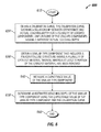
- FIG 8 is a flowchart depicting a microstructural quality determination method 800 in accordance with an exemplary embodiment of the present invention.
- Figure 8 shows a series of steps depicted in a certain order, the order of one or more steps can be rearranged, combined into fewer steps, and/or separated into more steps than that shown in other exemplary embodiments.
- the microstructural quality determination method 800 begins at step 810.
- the microstructural quality determination method 800 proceeds to step 820.
- one or more leached components that include a polycrystalline structure is obtained from a same leached batch.
- the same leached batch is a group of components that were leached in the same leaching process at the same time.
- the polycrystalline structure includes a leached layer and a non-leached layer being positioned adjacently below the leached layer.
- the non-leached layer includes a plurality of catalyst material therein, while the leached layer has had at least a portion of the catalyst material removed.
- the microstructural quality determination method 800 proceeds to step 830.
- a plurality of capacitance values are measured for each of the leached components.
- the capacitance values are determined using the capacitance measuring system 400 ( Figure 4 ) or the capacitance measuring system 500 ( Figure 5 ).
- the microstructural quality determination method 800 proceeds to step 840.
- an amount of data scattering is determined for each leached component.
- the amount of data scattering for a leached component is determined by a differential between the highest measured capacitance and the lowest measured capacitance for that leached component and by statistical results of where each measured capacitance lies.
- the microstructural quality determination method 800 proceeds to step 850.
- a quality of the leached component is determined based upon the amount of data scattering.
- the quality of the leached component relates to the microstructural quality and/or the leaching quality.
- the microstructural quality relates to the porosity of the microstructure.
- the microstructural quality is a good quality when there is low porosity. Conversely, the microstructural quality is a poor quality when there is high porosity.
- the leaching quality is a good quality when there is less catalyst materials present within the leached layer of the polycrystalline structure. Conversely, the leaching quality is a poor quality when there is more catalyst materials present within the leached layer of the polycrystalline structure.
- the quality of the leached component is considered to be good when the amount of data scattering is determined to be small. Conversely, the quality of the leached component is considered to be poor when the amount of data scattering is determined to be large. The relative terms of small and large are determined when comparing the data scattering of a first leached component to the data scattering of a second leached component that was leached in the same batch as the first leached component.
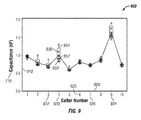
- Figure 9 is a data scattering chart 900 that shows the measured capacitance 710 for a plurality of leached cutters 922 from a same leaching batch in accordance with an exemplary embodiment of the present invention.
- the data scattering chart 900 includes a cutter number axis 920 and a capacitance axis 910.
- the cutter number axis 920 includes the number of the cutters 922 tested.
- the capacitance axis 910 includes values for the measured capacitance 710.
- a capacitance data point 930 is obtained by measuring the capacitance of the cutter 922, or leached component 922, using the capacitance measuring system 400 ( Figure 4 ), the capacitance measuring system 500 ( Figure 5 ), or a similar type system.
- Each capacitance data point 930 is plotted on the data scattering chart 900.
- Each leached component 922 has its capacitance measured a plurality of times. In some exemplary embodiments, five capacitance data points 930 are obtained for each leached component 922, however, the number of measurements is greater or fewer in other exemplary embodiments. In some exemplary embodiments, a twenty-five percentile marking 950, a fifty percentile marking 952 (or average), and a seventy-five percentile marking 954 is shown in the chart 900 for each leached component 922,. The area between the twenty-five percentile marking 950 and the seventy-five percentile marking 954 is shaded.
- the amount of data scattering is ascertained using this data scattering chart 900 and can be one or more of a differential between the highest and lowest capacitance measurements 710 for each leached component 922, a range between the twenty-five percentile marking 950 and the seventy-five percentile marking 954, or some similar observation made from the data scattering chart 900.
- cutter number 4 923 and cutter number 9 924 have a larger data scattering than for example cutter number 6 925 or cutter number 7 926.
- cutter number 4 923 and cutter number 9 924 have a poor leaching quality and/or a poor microstructural quality within the polycrystalline structure.
- the increase in amount of catalyst material within the polycrystalline structure causes this data scattering.
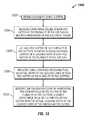
- FIG 10 is a flowchart depicting a non-destructive method 1000 of characterizing a quality of a PDC cutter in accordance with an exemplary embodiment of the present invention.
- the method 1000 includes obtaining a PDC cutter at step 1002.
- the PDC cutter 300 of Figure 3 may be obtained for characterizing the quality of the PDC cutter 300.
- the PDC cutter obtained at step 1002 includes a leached layer and an unleached layer, and the unleached layer is positioned adjacent to the leached layer.
- the PDC cutter 300 has the leached layer 354 and the unleached layer 356 adjacent to the leached layer 354.
- the leached layer of the PDC cutter has at least a portion of a catalyst material removed from within the leached layer.
- the method 1000 includes measuring capacitance values of the PDC cutter at multiple frequencies of an electrical signal.
- the electrical signal is provided to the PDC cutter by a capacitance measuring device to measure the capacitance values of the PDC cutter.
- the electrical signal may result in a voltage differential across surfaces of the PDC cutter due to capacitive characteristics of the portions of the PDC cutter, such as the leached layer.
- the capacitance measuring device of Figures 4 and 5 may be used to measure the capacitance values of the PDC cutter (e.g., the PDC cutter 300 of Figure 3 ) at multiple frequencies of an electrical signal.
- the capacitance measuring device 410 may provide an electrical signal to the PDC cutter 300 to measure capacitance values of the PDC cutter 300 at different frequencies of the electrical signal.
- the capacitance measuring device 410 may provide the electrical signal to the PDC cutter through the first wire 430.
- the capacitance measuring device 410 automatically changes the frequency of the electrical signal and measures the capacitance value of the PDC cutter after every change in the frequency.
- the frequency of the electrical signal provided to the PDC cutter may be changed manually and a capacitance value of the PDC cutter may be measured by the capacitance measuring device 400 after each manual change in frequency.
- the frequency of the electrical signal may be changed within a range of approximately 0 Hertz to approximately 10 Megahertz at a particular frequency increment or decrement. In some alternative embodiments, the frequency of the electrical signal may be changed within other ranges of frequency.
- the capacitance measuring device 400 may automatically sweep through a range of frequencies of the electrical signal at a particular frequency increment and may measure the capacitance of the PDC cutter after each increment in the frequency.
- the method 1000 includes characterizing a quality of the PDC cutter based on the capacitance values.
- each capacitance value of the capacitance values is measured at a respective frequency of the multiple frequencies of the electrical signal.
- characterizing the quality of the PDC cutter includes determining a lowest capacitance value from among the capacitance values. To illustrate, after multiple capacitance values of the PDC cutter (e.g., the PDC cutter 300) are measured at the multiple frequencies within a range of frequencies, the lowest capacitance value from among the multiple capacitance values is identified. For example, the lowest capacitance values may be 70 picofarad (pF) for a particular PDC cutter.
- pF picofarad
- characterizing the quality of the PDC cutter further includes determining, using capacitance to leaching depth mapping information, a leaching depth value that corresponds to the lowest capacitance value.
- the leaching depth value is an estimate of the actual depth of the leached layer of the PDC cutter.
- the leaching depth value is consider to be an estimate of the depth of the leached layer 354.
- the capacitance to leaching depth mapping information may be obtained from a calibration curve (e.g., a calibration curve shown in Figure 12 ).
- the method 1000 may also include obtaining (e.g., by generating) a calibration curve that may be used for mapping the lowest capacitance value to a leaching depth value.
- the capacitance to leaching depth mapping information may be in other forms, such as a formula, that may be used to calculate the leaching depth value using the lowest capacitance value as an input.
- the method 1000 may include cleaning the leached layer to remove one or more by-product materials deposited within the leached layer during a leaching process that removes at least a portion of the catalyst material to form the leached layer.
- the leached layer of the PDC cutter obtained at step 1002 may have been cleaned prior to measuring capacitance values of the PDC cutter at step 1004.
- the method 1000 is generally applicable to a leached component that may be obtained at step 1002.
- a leached component i.e., the PDC cutter or another type of leached component
- the leached component includes a polycrystalline structure that includes a leached layer and an unleached layer, where the leached layer has at least a portion of a catalyst material removed from therein.
- the method 1000 may include measuring capacitance values of the leached component at multiple frequencies of the electrical signal.
- the electrical signal is provided to the leached component by a capacitance measuring device to measure capacitance of the leached component in a similar manner described above with respect to the PDC cutter.
- the method includes characterizing a quality of the leached component based on the capacitance values. As described above with respect to the PDC cutter and step 1006 of the method 1000, each capacitance value of the capacitance values of the leached component is measured at a respective frequency of the multiple frequencies of the electrical signal. Characterizing the quality of the leached component includes determining a lowest capacitance value from among the capacitance values measured in a similar manner described above with respect to the PDC cutter and step 1004.
- the method 1000 may instead be implemented based on impedance measurement and impedance values (in units of ohms) in a manner similar to the steps described above without departing from the scope of this disclosure.
- an impedance measuring device may be used to measure impedance values of the PDC cutter and the quality of the PDC cutter may be characterized using the impedance values, for example, based on impedance to leaching depth mapping information.
- FIG 11 is a graph 1100 depicting capacitance values of a PDC cutter measured at multiple frequencies in accordance with an exemplary embodiment of the present invention.
- the PDC cutter may be the PDC cutter 300 of Figure 3 .
- frequency values in hertz
- capacitance values in picofarads
- the curve 1106 is a plot of measured capacitance values of the PDC cutter and corresponding frequency values of an electrical signal used in measuring the capacitance values of the PDC cutter.
- a capacitance measuring device such as the capacitance measuring device 410 of Figure 4 , may be used to measure capacitance values of the PDC cutter at multiple frequencies. For example, a frequency range of 10 kilohertz to 10 Megahertz is shown in the graph 1100. In some alternative embodiments, the frequency range may be narrower or wider than shown in the graph 1100.
- characterizing the quality of the PDC cutter includes determining the lowest capacitance value from among the capacitance values measured by the capacitance measuring device.
- the lowest capacitance value in the graph 1100 is at data point 1108, which is approximately 70 picofarads.
- the lowest capacitance value may be more precisely determined by displaying higher resolution intervals of the capacitance values on the y-axis 1104.
- the lowest capacitance value determined from the graph 1100 may be used to determine a leaching depth value, which is an estimate of an actual depth of a leached layer of the PDC cutter, such as the leached layer 354 of the PDC cutter 300 of Figure 3 .
- the graph 1100 may be generated by the capacitance measuring device, such as the capacitance measuring device 410 of Figure 4 .
- the graph 1100 may be generated based on measurement data (i.e., capacitance and frequency values) obtained from the capacitance measuring device.
- the graph 1100 illustrates capacitance values of a PDC cutter measured at multiple frequencies
- the graph 1100 may illustrate impedance values of the PDC cutter measured at multiple frequencies and may be generated and used a manner similar to the capacitance values described above without departing from the scope of this disclosure.
- Figure 12 illustrates a graph 1200 depicting a calibration curve 1206 that shows a relationship between capacitance values and leaching depth values for estimating an actual depth of a PDC cutter in accordance with an exemplary embodiment of the present invention.
- capacitance values in picofarads
- leach depth values in microns
- the generation of the calibration curve 1206 is described below in more detail with respect to Figure 13 .
- the graph 1200 may be used in the method 1000 of Figure 10 to characterize a quality of PDC cutters or other leached components.
- the PDC cutter e.g., the PDC cutter 300
- the lowest capacitance value from among the multiple capacitance values is determined as described with respect to Figures 10 and 11 .
- the calibration curve 1206 may be used to map the lowest capacitance value from the x-axis 1202 to a leaching depth value on the y-axis 1204. For example, if the lowest capacitance value is determined to be approximately 70 picofarads, the leaching depth value may be determined to be approximately 280 microns based on the calibration curve 1206.
- the leaching depth value determined using the graph 1200 is an estimate of the actual depth of the leached layer of the PDC cutter. To illustrate with respect to the PDC cutter 300 of Figure 3 , the leaching depth value determined using the calibration curve 1206 is an estimate of the actual depth of the leached layer 354 of the PDC cutter 300.
- the graph 1200 may be used to map capacitance values ranging from approximately 48 picofarads to 120 picofarads to corresponding leaching depth values ranging from approximately 70 microns to approximately 490 microns. Although particular ranges of capacitance and leaching depth values are shown in Figure 12 , in alternative embodiments, the graph 1200 may have wider or narrower ranges of capacitance and leaching depth values that may be used for reliably mapping capacitance values to leaching depth values as described above.
- Figure 12 illustrates the calibration curve 1206 that shows a relationship between capacitance values and leaching depth values for estimating an actual depth of a PDC cutter
- a calibration curve that shows a relationship between impedance values and leaching depth values may be generated and used for estimating an actual depth of a PDC cutter.
- a calibration curve that shows a relationship between impedance values and leaching depth values may be generated and used in a manner similar to the generation and use of the calibration curve 1206.
- Figure 13 is a flowchart depicting a method 1300 of generating a calibration curve for use in characterizing a quality of a PDC cutter in accordance with an exemplary embodiment of the present invention.
- the method 1300 may be used to generate the graph 1200 of Figure 12 .
- the method 1300 includes obtaining a plurality of PDC cutters.
- the plurality of PDC cutters are obtained for the purpose of generating a calibration curve (e.g., the calibration curve 1206 of Figure 12 ) or other capacitance to leaching depth mapping information (e.g., an equation or a mapping table) for use in estimating an actual depth of a leached layer of the same type PDC cutter using a method such as the method 1000 of Figure 10 .
- the method 1300 may include obtaining a plurality of the PDC cutters 300 of Figure 3 .
- the method 1300 includes measuring capacitance values of each PDC cutter of the plurality of PDC cutters at multiple frequencies of the electrical signal.
- the capacitance values of each PDC cutter of the plurality of PDC cutters may be measured at multiple frequencies of an electrical signal in a manner described above with respect to Figure 10 .
- the electrical signal is provided to each PDC cutter individually by a capacitance measuring device, such as the capacitance measuring device 400 of Figures 4 and 5 .
- the leached layer of each PDC cutter may be cleaned to remove one or more by-product materials deposited within the leached layer during a leaching process that removes at least a portion of the catalyst material to form the leached layer.
- the method 1300 may include cleaning the leached layer of each PDC cutter to remove the one or more by-product materials.
- each PDC cutter obtained at step 1302 may have a leached layer that has been cleaned remove one or more by-product materials.
- the method includes cutting each PDC cutter of the plurality of PDC cutters to expose a cross-sectional surface of a leached layer of each PDC cutter of the plurality of PDC cutters.
- a cross-section of the PDC cutter 300 is shown in Figure 3 , which illustrates a cross-sectional surface of the leached layer 354.
- the method 1300 includes measuring an actual depth of the leached layer of each PDC cutter of the plurality of PDC cutters. The actual depth may be measured using a distance measuring tool known to those of ordinary skill in the art with the benefit of this disclosure. A microscope or other similar magnifying device may be used to aid with the measuring of the actual depth of the leached layer.
- the actual depth of the leached layer of each PDC cutter of the plurality of PDC cutters may be measured in a similar manner described with respect to Figure 7 .
- the method 1300 may also include polishing the cross-sectional surface of the leached layer of each PDC cutter of the plurality of PDC cutters.
- the method 1300 includes generating the calibration curve by associating, for each particular PDC cutter of the plurality of PDC cutters, a lowest capacitance value of the capacitance values of the particular PDC cutter with the actual leaching depth of the leached layer of the particular PDC cutter.
- the lowest capacitance value among the capacitance values may be determined as described with respect to Figures 10 and 11 .
- the lowest capacitance value and the actual leaching depth value may be plotted as a data point in a graph such as the graph 1200 of Figure 12 .
- a best fit curve i.e., a calibration curve such as the calibration curve 1206 of Figure 12
- a calibration curve such as the calibration curve 1206 of Figure 12
- another format of the capacitance to leaching depth mapping information (e.g., an equation or a mapping table) may be generated based on the relationship between the lowest capacitance values of the plurality of PDC cutters and the actual leaching depths of the leaching layers of the plurality of PDC cutters.
- the calibration curve and other formats of the capacitance to leaching depth mapping information generated by the method 1300 may be used in a similar manner described above with respect to Figures 6 , 10 , and 12 for the purpose of estimating a leaching depth of the leaching layer of a PDC cutter that is of the same type as the plurality of the PDC cutters used in the generation of the calibration curve and other formats of the capacitance to leaching depth mapping information.
- the method 1300 may be implemented based on impedance values of the PDC cutter in a manner similar to the steps described above. For example, a calibration curve showing a relationship between impedance values and leaching depth values of the PDC cutters may be generated, and the quality of the PDC cutter may be characterized based on such calibration curve.
- FIG 14 illustrates a capacitance measuring system 1400 for characterizing a quality of a PDC cutter in accordance to an exemplary embodiment of the present invention.
- the system 1400 may be used to implement the method 1000 of Figure 10 and the method 1300 of Figure 13 .
- the system 1400 includes the capacitance measuring device 410, also shown in Figures 4 and 5 .
- the capacitance measuring device 410 may be Instek LCR-8110G LCR meter.
- the capacitance measuring device 410 has the terminal 418 and the terminal 419 as shown in Figure 4 .
- the system 1400 includes a first cap 1402 and a second cap 1404 that are electrical conductive.
- the system 1400 also includes a PDC cutter, such as the PDC cutter 300 shown in Figures 3 and 5 .
- a PDC cutter such as the PDC cutter 300 shown in Figures 3 and 5 .
- the PDC cutter is blocked from view by the first cap 1402 and the second cap 1404.
- the PDC cutter has a leached layer and an unleached layer that is adjacent to the leached layer.
- the leached layer has at least a portion of a catalyst material removed from therein using a leaching process.
- the PDC cutter may have been cleaned to remove one or more by-product materials deposited within the leached layer during a leaching process that removes at least a portion of the catalyst material to form the leached layer.
- the system 1400 also includes a first wire 1410 electrically coupling the first terminal of the capacitance measuring device 410 to a first surface of the PDC cutter.
- the first surface of the PDC cutter may be the cutting surface 312 of the PDC cutter 300 shown in Figures 3 and 5 .
- the system 1400 further includes a second wire 1412 electrically coupling the second terminal of the capacitance measuring device 410 to a second surface of the PDC cutter.
- the second surface of the PDC cutter may be the bottom surface 454 of the PDC cutter 300 shown in Figure 4 .
- the first (cutting) surface 312 and the second (bottom) surface 454 of the PDC cutter 300 are on opposite sides of the leached layer 354, and the first surface 312 is a surface of the leached layer 354.
- the capacitance measuring device 410 provides an electrical signal to the PDC cutter, such as the PDC cutter 300, to measure capacitance values of the PDC cutter.
- the capacitance measuring device 410 measures the capacitance values of the PDC cutter at multiple frequencies of the electrical signal.
- the capacitance measuring device 410 can measure the capacitance values of a PDC cutter at multiple frequencies of the electrical signal in the method 1000 as well as the method 1300.
- the first cap 1402 is coupled to the first surface of the PDC cutter, such as the cutting surface 312 of the PDC cutter 300.
- the second cap 1404 may be coupled to the second surface of the PDC cutter, such as the bottom surface 454 of the PDC cutter 300.
- a portion of the PDC cutter including the second surface of the PDC may be positioned in a cavity of the second cap 1404.
- the cavity of the second cap 1404 is illustrated in Figure 16 .
- at least a portion of the substrate 350 of the PDC cutter 300 may be positioned in cavity of the second cap 1404.
- the first wire 1410 is electrically coupled to the first cap 1402, and the second wire 1412 is electrically coupled to the second cap 1404.
- the system 1400 may include an electrically conductive terminal 1406 attached to a piston 1408, which may be vertically moveable. As illustrated in Figure 14 , the first wire 1410 is physically attached to the terminal 1406, and the terminal 1406 may be lowered to the position shown in Figure 14 and in contact with the cap 1402. The second wire 1412 may be directly attached to the second cap 1404 as illustrated in Figure 14 .
- a PDC cutter such as the PDC cutter 300 of Figure 3
- the second surface and/or another part of the substrate of the PDC cutter e.g., the bottom surface 454 or another part of the substrate 350 of the PDC cutter 300
- the first surface such as the cutting surface 312 or another part of the leached layer 354, does not come in physical contact with a conductive surface of the second cap 1404.
- the first cap 1402 is positioned on the PDC cutter such that a conductive surface of the first cap 1402 is in physical contact with the first surface of the PDC cutter, such as the cutting surface 312 of the PDC cutter 300.
- the electrically conductive terminal 1406 may then be lowered by the piston 1408 such that the electrically conductive terminal 1406 comes in physical contact with the first cap 1402.
- the first cap 1402 may first attached to the electrically conductive terminal 1406 and lowered until the conductive surface of the first cap 1402 comes in physical contact with the first surface of the PDC cutter, such the cutting surface 312 of the PDC cutter 300.
- the capacitance measuring device 410 may start measuring the capacitances values of the PDC cutter at multiple frequencies of electrical signal provided by the capacitance measuring device 410 to the PDC cutter via one of the wires 1410, 1412. As described above, the multiple frequencies of the electrical signal may range between approximately 0 Hertz and approximately 10 Megahertz or other suitable frequency values depending on, for example, the type of PDC cutter.
- Figure 14 described as illustrating the capacitance measuring system 1400, in some alternative embodiments, the system 1400 may be used as an impedance measuring system in a similar manner described above without departing from the scope of this disclosure.
- Figure 15 illustrates the first cap 1402 used in the capacitance measuring system 1400 of Figure 14 in accordance to an exemplary embodiment of the present invention.
- the first cap 1402 has an electrically conductive surface 1502 and an electrically insulated surface 1504.
- the electrically conductive surface 1502 is designed to come in contact with the first surface of the PDC cutter, such as the cutting surface 312 of the PDC cutter 300.
- the electrically insulated surface 1504 is designed to electrically isolate the electrically conductive surface 1502 and any other electrically conductive part of the first cap 1402 from coming in contact with the PDC cutter as well as the second cap 1404.
- the conductive surface 1502 may have ring shape having particular thickness.
- the conductive surface 1502 may be shaped and sized such that the conductive surface 1502 is physical contact with the cutting surface 312 of the PDC cutter 300 proximal to the outer perimeter of the cutting surface 312.
- the conductive surface 1502 may be shaped and sized to come in contact with other parts of the conductive surface 1502 including the entire cutting surface 312.
- the electrically conductive surface 1502 and other parts of the first cap 1402 may be made from copper or another electrically conductive material.
- the electrically insulated surface 1504 may be made from plastic or another electrically nonconductive material.
- first cap 1402 is shown as having a cylindrical shape, in alternative embodiments, the first cap 1402 may have other shapes without departing from the scope of this disclosure. In some alternative embodiments, the first cap 1402 may be used in the system 1400 for measuring impedance of a PDC cutter.
- Figure 16 illustrates the second cap 1404 used in conjunction with the first cap 1402 in the capacitance measuring system 1500 of Figure 14 in accordance to an exemplary embodiment of the present invention.
- the second cap 1404 has a cavity 1604 bound by a wall 1602 including a bottom wall (not shown) of the second cap 1404.
- the PDC cutter 300 may be positioned within the cavity 1604 such that the bottom surface 454 of the PDC cutter 300 come in contact with the surface of the second cap 1404.
- the second cap 1404 may be made from copper or another electrically conductive material.
- the second cap 1404 is shown as having a cylindrical shape, in alternative embodiments, the second cap 1404 may have other shapes without departing from the scope of this disclosure. In some alternative embodiments, the second cap 1404 may be used in the system 1400 for measuring impedance of a PDC cutter.
- a quantity of PDC cutters being leached within the same leaching batch are provided, such as one thousand PDC cutters
- the capacitance of the PDC cutters are measured pursuant to the descriptions provided above.
- the PDC cutters that meet a desired quality and/or leaching depth are kept while the remaining PDC cutters that do not meet the desired leaching depth and/or quality are returned.
- one thousand PDC cutters being leached from the same batch are provided, two hundred PDC cutters, or twenty percent, may be retained while the remaining are returned.
- only the higher quality and/or the proper leaching depth PDC cutters are paid for and retained, which results in the PDC cutters performing better during their application.
Landscapes
- Chemical & Material Sciences (AREA)
- Health & Medical Sciences (AREA)
- Life Sciences & Earth Sciences (AREA)
- Pathology (AREA)
- Physics & Mathematics (AREA)
- Analytical Chemistry (AREA)
- Biochemistry (AREA)
- General Health & Medical Sciences (AREA)
- General Physics & Mathematics (AREA)
- Immunology (AREA)
- Food Science & Technology (AREA)
- Medicinal Chemistry (AREA)
- Engineering & Computer Science (AREA)
- Chemical Kinetics & Catalysis (AREA)
- Electrochemistry (AREA)
- Investigating Or Analyzing Materials By The Use Of Electric Means (AREA)
Applications Claiming Priority (1)
| Application Number | Priority Date | Filing Date | Title |
|---|---|---|---|
| US14/286,136 US9377428B2 (en) | 2012-02-21 | 2014-05-23 | Non-destructive leaching depth measurement using capacitance spectroscopy |
Publications (1)
| Publication Number | Publication Date |
|---|---|
| EP2947452A1 true EP2947452A1 (de) | 2015-11-25 |
Family
ID=53039332
Family Applications (1)
| Application Number | Title | Priority Date | Filing Date |
|---|---|---|---|
| EP15166121.2A Withdrawn EP2947452A1 (de) | 2014-05-23 | 2015-05-01 | Zerstörungsfreie versickerungstiefenmessung unter verwendung von kapazitätsspektroskopie |
Country Status (2)
| Country | Link |
|---|---|
| EP (1) | EP2947452A1 (de) |
| WO (1) | WO2015179091A1 (de) |
Cited By (1)
| Publication number | Priority date | Publication date | Assignee | Title |
|---|---|---|---|---|
| CN114660134A (zh) * | 2022-05-17 | 2022-06-24 | 中国石油大学(华东) | 基于叉指电容传感器的非金属材料老化检测装置与方法 |
Citations (4)
| Publication number | Priority date | Publication date | Assignee | Title |
|---|---|---|---|---|
| DE102005040296A1 (de) * | 2005-08-21 | 2007-02-22 | Hahn-Meitner-Institut Berlin Gmbh | Messverfahren zur in-situ-Kontrolle des chemischen Ätzvorgangs von latenten Ionenspuren |
| EP2631638A2 (de) * | 2012-02-21 | 2013-08-28 | Varel International, Ind., L.P. | Verwendung von Kapazität zum Analysieren eines polykristallinen Diamanten |
| US20140062509A1 (en) * | 2012-02-21 | 2014-03-06 | Varel International Ind., L.P. | Method and Apparatus to Assess the Thermal Damage Caused to a PCD Cutter Using Capacitance Spectroscopy |
| US20140253149A1 (en) * | 2012-02-21 | 2014-09-11 | Varel International Ind., L.P. | Non-Destructive Leaching Depth Measurement Using Capacitance Spectroscopy |
Family Cites Families (3)
| Publication number | Priority date | Publication date | Assignee | Title |
|---|---|---|---|---|
| EP1637875A1 (de) * | 2004-09-17 | 2006-03-22 | Fondazione Torino Wireless | Kapazitiver Mehrfrequenzsensor und Verfahren zur dessen Betreibung |
| US9128031B2 (en) * | 2012-02-21 | 2015-09-08 | Varel International Ind., L.P. | Method to improve the leaching process |
| US20130214769A1 (en) * | 2012-02-21 | 2013-08-22 | Varel International Ind., L.P. | Use of Capacitance And Eddy Currents to Analyze Polycrystalline Diamond |
-
2015
- 2015-04-29 WO PCT/US2015/028308 patent/WO2015179091A1/en not_active Ceased
- 2015-05-01 EP EP15166121.2A patent/EP2947452A1/de not_active Withdrawn
Patent Citations (4)
| Publication number | Priority date | Publication date | Assignee | Title |
|---|---|---|---|---|
| DE102005040296A1 (de) * | 2005-08-21 | 2007-02-22 | Hahn-Meitner-Institut Berlin Gmbh | Messverfahren zur in-situ-Kontrolle des chemischen Ätzvorgangs von latenten Ionenspuren |
| EP2631638A2 (de) * | 2012-02-21 | 2013-08-28 | Varel International, Ind., L.P. | Verwendung von Kapazität zum Analysieren eines polykristallinen Diamanten |
| US20140062509A1 (en) * | 2012-02-21 | 2014-03-06 | Varel International Ind., L.P. | Method and Apparatus to Assess the Thermal Damage Caused to a PCD Cutter Using Capacitance Spectroscopy |
| US20140253149A1 (en) * | 2012-02-21 | 2014-09-11 | Varel International Ind., L.P. | Non-Destructive Leaching Depth Measurement Using Capacitance Spectroscopy |
Cited By (2)
| Publication number | Priority date | Publication date | Assignee | Title |
|---|---|---|---|---|
| CN114660134A (zh) * | 2022-05-17 | 2022-06-24 | 中国石油大学(华东) | 基于叉指电容传感器的非金属材料老化检测装置与方法 |
| CN114660134B (zh) * | 2022-05-17 | 2022-08-19 | 中国石油大学(华东) | 基于叉指电容传感器的非金属材料老化检测装置与方法 |
Also Published As
| Publication number | Publication date |
|---|---|
| WO2015179091A1 (en) | 2015-11-26 |
Similar Documents
| Publication | Publication Date | Title |
|---|---|---|
| EP2631638B1 (de) | Verwendung von Kapazität zum Analysieren eines polykristallinen Diamanten | |
| US9423436B2 (en) | Method and apparatus to assess the thermal damage caused to a PCD cutter using capacitance spectroscopy | |
| EP2631637A2 (de) | Verwendung von Kapazitäts- und Wirbelströmen zur Analyse eines Polykristalldiamanten | |
| EP2631640A2 (de) | Verwendung von Wirbelströmen zur Analyse eines Polykristalldiamanten | |
| US9128031B2 (en) | Method to improve the leaching process | |
| US9377428B2 (en) | Non-destructive leaching depth measurement using capacitance spectroscopy | |
| US20170043378A1 (en) | Apparatus to improve the performance of a leached cutter | |
| CA2882113C (en) | Methods for forming instrumented cutting elements of an earth-boring drilling tool | |
| EP2631313A2 (de) | Verfahren zur Verbesserung der Leistung eines ausgelaugten Schneidwerkzeugs | |
| US9784313B1 (en) | Methods for screening PCD elements for EDM processing and methods for EDM processing such PCD elements | |
| EP2947452A1 (de) | Zerstörungsfreie versickerungstiefenmessung unter verwendung von kapazitätsspektroskopie | |
| EP3066482B1 (de) | Verfahren zur beurteilung der wärmeschäden eines schneiders mithilfe von kapazitätsspektroskopie | |
| CN112782211B (zh) | 一种水相变的探测方法 | |
| US11965848B2 (en) | Method for determining the electrical properties of a core sample | |
| CN103176055A (zh) | 层状结构岩石垂直纹理方向介电性质测量样品的制备方法 |
Legal Events
| Date | Code | Title | Description |
|---|---|---|---|
| PUAI | Public reference made under article 153(3) epc to a published international application that has entered the european phase |
Free format text: ORIGINAL CODE: 0009012 |
|
| AK | Designated contracting states |
Kind code of ref document: A1 Designated state(s): AL AT BE BG CH CY CZ DE DK EE ES FI FR GB GR HR HU IE IS IT LI LT LU LV MC MK MT NL NO PL PT RO RS SE SI SK SM TR |
|
| AX | Request for extension of the european patent |
Extension state: BA ME |
|
| STAA | Information on the status of an ep patent application or granted ep patent |
Free format text: STATUS: THE APPLICATION IS DEEMED TO BE WITHDRAWN |
|
| 18D | Application deemed to be withdrawn |
Effective date: 20160526 |