EP2949845B1 - Articulation de volet réglable - Google Patents
Articulation de volet réglable Download PDFInfo
- Publication number
- EP2949845B1 EP2949845B1 EP15167919.8A EP15167919A EP2949845B1 EP 2949845 B1 EP2949845 B1 EP 2949845B1 EP 15167919 A EP15167919 A EP 15167919A EP 2949845 B1 EP2949845 B1 EP 2949845B1
- Authority
- EP
- European Patent Office
- Prior art keywords
- adjusting
- rotary bearing
- flap
- face
- contour
- Prior art date
- Legal status (The legal status is an assumption and is not a legal conclusion. Google has not performed a legal analysis and makes no representation as to the accuracy of the status listed.)
- Active
Links
Images

Classifications
-
- E—FIXED CONSTRUCTIONS
- E05—LOCKS; KEYS; WINDOW OR DOOR FITTINGS; SAFES
- E05D—HINGES OR SUSPENSION DEVICES FOR DOORS, WINDOWS OR WINGS
- E05D7/00—Hinges or pivots of special construction
- E05D7/04—Hinges adjustable relative to the wing or the frame
- E05D7/0415—Hinges adjustable relative to the wing or the frame with adjusting drive means
-
- E—FIXED CONSTRUCTIONS
- E05—LOCKS; KEYS; WINDOW OR DOOR FITTINGS; SAFES
- E05D—HINGES OR SUSPENSION DEVICES FOR DOORS, WINDOWS OR WINGS
- E05D15/00—Suspension arrangements for wings
- E05D15/26—Suspension arrangements for wings for folding wings
- E05D15/262—Suspension arrangements for wings for folding wings folding vertically
-
- E—FIXED CONSTRUCTIONS
- E05—LOCKS; KEYS; WINDOW OR DOOR FITTINGS; SAFES
- E05D—HINGES OR SUSPENSION DEVICES FOR DOORS, WINDOWS OR WINGS
- E05D15/00—Suspension arrangements for wings
- E05D15/26—Suspension arrangements for wings for folding wings
- E05D15/264—Suspension arrangements for wings for folding wings for bi-fold wings
-
- E—FIXED CONSTRUCTIONS
- E05—LOCKS; KEYS; WINDOW OR DOOR FITTINGS; SAFES
- E05F—DEVICES FOR MOVING WINGS INTO OPEN OR CLOSED POSITION; CHECKS FOR WINGS; WING FITTINGS NOT OTHERWISE PROVIDED FOR, CONCERNED WITH THE FUNCTIONING OF THE WING
- E05F1/00—Closers or openers for wings, not otherwise provided for in this subclass
- E05F1/08—Closers or openers for wings, not otherwise provided for in this subclass spring-actuated, e.g. for horizontally sliding wings
- E05F1/10—Closers or openers for wings, not otherwise provided for in this subclass spring-actuated, e.g. for horizontally sliding wings for swinging wings, e.g. counterbalance
- E05F1/1041—Closers or openers for wings, not otherwise provided for in this subclass spring-actuated, e.g. for horizontally sliding wings for swinging wings, e.g. counterbalance with a coil spring perpendicular to the pivot axis
- E05F1/105—Closers or openers for wings, not otherwise provided for in this subclass spring-actuated, e.g. for horizontally sliding wings for swinging wings, e.g. counterbalance with a coil spring perpendicular to the pivot axis with a compression spring
- E05F1/1058—Closers or openers for wings, not otherwise provided for in this subclass spring-actuated, e.g. for horizontally sliding wings for swinging wings, e.g. counterbalance with a coil spring perpendicular to the pivot axis with a compression spring for counterbalancing
-
- E—FIXED CONSTRUCTIONS
- E05—LOCKS; KEYS; WINDOW OR DOOR FITTINGS; SAFES
- E05F—DEVICES FOR MOVING WINGS INTO OPEN OR CLOSED POSITION; CHECKS FOR WINGS; WING FITTINGS NOT OTHERWISE PROVIDED FOR, CONCERNED WITH THE FUNCTIONING OF THE WING
- E05F1/00—Closers or openers for wings, not otherwise provided for in this subclass
- E05F1/08—Closers or openers for wings, not otherwise provided for in this subclass spring-actuated, e.g. for horizontally sliding wings
- E05F1/10—Closers or openers for wings, not otherwise provided for in this subclass spring-actuated, e.g. for horizontally sliding wings for swinging wings, e.g. counterbalance
- E05F1/1041—Closers or openers for wings, not otherwise provided for in this subclass spring-actuated, e.g. for horizontally sliding wings for swinging wings, e.g. counterbalance with a coil spring perpendicular to the pivot axis
- E05F1/1066—Closers or openers for wings, not otherwise provided for in this subclass spring-actuated, e.g. for horizontally sliding wings for swinging wings, e.g. counterbalance with a coil spring perpendicular to the pivot axis with a traction spring
- E05F1/1075—Closers or openers for wings, not otherwise provided for in this subclass spring-actuated, e.g. for horizontally sliding wings for swinging wings, e.g. counterbalance with a coil spring perpendicular to the pivot axis with a traction spring for counterbalancing
-
- E—FIXED CONSTRUCTIONS
- E05—LOCKS; KEYS; WINDOW OR DOOR FITTINGS; SAFES
- E05Y—INDEXING SCHEME ASSOCIATED WITH SUBCLASSES E05D AND E05F, RELATING TO CONSTRUCTION ELEMENTS, ELECTRIC CONTROL, POWER SUPPLY, POWER SIGNAL OR TRANSMISSION, USER INTERFACES, MOUNTING OR COUPLING, DETAILS, ACCESSORIES, AUXILIARY OPERATIONS NOT OTHERWISE PROVIDED FOR, APPLICATION THEREOF
- E05Y2201/00—Constructional elements; Accessories therefor
- E05Y2201/40—Motors; Magnets; Springs; Weights; Accessories therefor
- E05Y2201/404—Function thereof
- E05Y2201/416—Function thereof for counterbalancing
-
- E—FIXED CONSTRUCTIONS
- E05—LOCKS; KEYS; WINDOW OR DOOR FITTINGS; SAFES
- E05Y—INDEXING SCHEME ASSOCIATED WITH SUBCLASSES E05D AND E05F, RELATING TO CONSTRUCTION ELEMENTS, ELECTRIC CONTROL, POWER SUPPLY, POWER SIGNAL OR TRANSMISSION, USER INTERFACES, MOUNTING OR COUPLING, DETAILS, ACCESSORIES, AUXILIARY OPERATIONS NOT OTHERWISE PROVIDED FOR, APPLICATION THEREOF
- E05Y2201/00—Constructional elements; Accessories therefor
- E05Y2201/60—Suspension or transmission members; Accessories therefor
- E05Y2201/622—Suspension or transmission members elements
- E05Y2201/624—Arms
-
- E—FIXED CONSTRUCTIONS
- E05—LOCKS; KEYS; WINDOW OR DOOR FITTINGS; SAFES
- E05Y—INDEXING SCHEME ASSOCIATED WITH SUBCLASSES E05D AND E05F, RELATING TO CONSTRUCTION ELEMENTS, ELECTRIC CONTROL, POWER SUPPLY, POWER SIGNAL OR TRANSMISSION, USER INTERFACES, MOUNTING OR COUPLING, DETAILS, ACCESSORIES, AUXILIARY OPERATIONS NOT OTHERWISE PROVIDED FOR, APPLICATION THEREOF
- E05Y2900/00—Application of doors, windows, wings or fittings thereof
- E05Y2900/20—Application of doors, windows, wings or fittings thereof for furniture, e.g. cabinets
Definitions
- the invention relates to a device for moving a folding flap movably received on a furniture body and to a piece of furniture.
- a folding flap In order to cover, for example, a larger area of a furniture front of a piece of furniture with a flap which can be pivoted about an in particular horizontal axis of rotation, it is known in the field of furniture construction to design the flap as a folding flap.
- the folding flap can have at least two flap elements which are articulated e.g. are hinged together and which e.g. fold up around another horizontal swivel axis.
- the flap requires less swivel space.
- a folding flap can have a reduced lever length, in particular in an open position, and requires a comparatively low force and e.g. a correspondingly smaller mechanical energy store to hold a flap in an open position.
- the folding flap includes additional moving parts compared to a simple, one-piece flap, which means e.g. repeatable precise movement control and e.g. a tight seal of the furniture may be difficult to reach.
- the present invention has for its object to provide a device for moving a folding flap movably received on a furniture body, which is improved with regard to the adjustability of a movement guide.
- the invention is based on a device for moving a folding flap that is movably received on a furniture body, the folding flap comprising at least two hingedly connected flap elements.
- the device is equipped with a force unit which at least supports the opening of the folding flap by the application of force via an actuating arm which is arranged on a first flap element in the assembled state.
- the device is equipped with a second actuating arm which is connected to a second flap element in the assembled state. At least one of the two actuating arms is attached to the respectively assigned flap element by means of a joint.
- the joint comprises a pivot bearing unit with an adjusting device, with which a position of a pivot bearing of the at least one adjusting arm, through which an axis of rotation of the adjusting arm runs, on the associated flap element, is adjustable, the adjusting device being an adjusting element with a spiral Includes adjustment contour, which is rotatably mounted for adjusting the position of a pivot bearing element on the pivot bearing unit.
- a spiral-shaped adjustment contour can advantageously be designed to be self-locking, a selected setting being fixable on the adjustment device with an advantageously small force.
- a spiral adjustment contour enables additional adjustment positions to be made available by adjustment by more than one full rotation, ie by an adjustment angle of 360 ° of the rotatable adjustment element.
- the adjustment contour can advantageously provide a comparatively large adjustment area between a center and an outer edge of the spiral adjustment contour for adjusting a position of the engagement structure.
- a comparatively fine and precise adjustability of the adjustment device can be achieved by an adjustment movement that extends beyond a 360 ° rotation.
- the pivot bearing unit comprises an attachment element for attachment to the flap element of the at least one actuating arm, on which the pivot bearing element is adjustably mounted by means of an adjusting device.
- the pivot bearing element can be adjusted by an arc-shaped movement about a pivot axis, the pivot axis being different from the axis of rotation.
- the pivot bearing element can additionally be adjustable by a straight movement.
- the adjustment element engages with the spiral-shaped adjustment contour on an engagement structure of the attachment element.
- the engaging structure is designed as a cam-shaped projection with a circular or elliptical cross-section in order to enable the adjusting element to be adjusted relatively easily.
- the attachment element is preferably provided for a fixed attachment to the corresponding flap element in order to provide a fixed reference point and a stable base on the flap element for adjusting the articulated connection of the actuating arm.
- the adjustment contour is preferably formed on an end face of the adjustment element between two parallel planes which are perpendicular to an adjustment axis of rotation. As a result, the adjustment contour can advantageously be carried out in a space-saving and stable form.
- the adjustment element comprises a disc on which the spiral adjustment contour is formed in a web-like manner on one end.
- the end face is preferably a circular disk-shaped flat surface.
- the center of the spiral is located concentrically to the circular disk-shaped end face, as a result of which adjustment forces for different adjustments differ comparatively little.
- the adjustment element can also comprise a disk on which the spiral adjustment contour is formed on one end face as a groove-shaped depression.
- the end face can optionally provide a comparatively large contact area for fixing.
- a preferred embodiment of the invention consists in that a bearing pin is formed so as to protrude centrally on an end face of the adjusting element, which is arranged opposite the end face of the adjusting contour.
- the bearing pin preferably has a smaller diameter than the disk.
- an engagement for an adjustment tool such as, for example, a screwdriver is formed on an end face of the adjustment element, which is located opposite the end face of the adjustment contour, and in particular on the bearing journal.
- the adjusting device can thereby advantageously be of compact design.
- a second bearing pin can preferably protrude centrally from the end face, in order to rotatably support the adjustment element on both sides, in particular symmetrically with respect to the adjustment contour.
- An angular position of the adjustment element can preferably be fixed with a screw connection between the pivot bearing element and the attachment element. Further or more screw connections can also be provided.
- a number of bores for a fixing screw connection between the pivot bearing element and the attachment element are formed on the pivot bearing element and / or on the attachment element, which are in particular provided with an internal thread adapted to a fixing screw.
- the through openings can be spaced e.g. a maximum travel of the adjustment element and e.g. a double maximum travel of the adjusting element.
- the adjustment device can thus be used at different positions at which the two control arm sections can be connected to one another.
- the row of bores enables the adjustment arm to be adjusted over a comparatively large length range, the adjustment device with the spiral-shaped adjustment contour being available for fine adjustment of the length of the adjustment arm.
- the adjusting device preferably comprises a bearing body, which surrounds the adjusting element perpendicular to the adjusting axis of rotation, the bearing body being provided for arrangement between the rotary bearing element and the attachment element.
- the bearing body can contribute to the fixation or to a rough positioning of the adjusting element, as a result of which the adjusting device and the actuating arm can be made more stable, since not only does the adjusting element provide support between the two actuating arm sections, but also the bearing body.
- the adjusting element is mounted in the bearing body in such a way that the adjusting element projects beyond its surface on at least one side of the bearing body in the direction of the axis of rotation.
- FIG. 1 An embodiment of a piece of furniture according to the invention is shown. It is in the Figure 1 A section of a furniture compartment 2 of the furniture 1 is shown, on which a multi-part furniture flap 3 with an exemplary embodiment of an actuating device 4 according to the invention is attached in order to attach the furniture flap to the furniture compartment 2 so that it can be opened or closed.
- the furniture flap 3 is formed in two parts and comprises a first flap element 3a and a second flap element 3b.
- the adjusting device 4 comprises a mounting element 4a and a first adjusting arm 6a and a second adjusting arm 6b, the two adjusting arms 6a and 6b being pivotably mounted on the mounting element 4a.
- An energy storage device 4b is also attached to the mounting element 4a, for example in the form of a plurality of cylindrical helical springs, which can transmit forces to the actuating arm 6a via a lever mechanism and absorb it from the actuating arm 6a.
- the mounting element 4a is fastened to a side wall 2c of the furniture compartment 2 near a furniture ceiling 2a and is screwed on, for example.
- the first adjusting arm 6a is firmly connected to the upper flap element 3a, the adjusting arm 6a preferably being designed to transmit weight forces of the two flap elements 3a and 3b and the hinge 5 to the mounting element 4a.
- the second actuating arm 6b is movably connected to the second flap element 3b via a joint 7.
- the actuating arm 6b is provided to guide the second flap element 3b into a predetermined closed position and to hold it there.
- Another task of the actuating arm 6b is to avoid an uncontrolled swinging of the flap element 3b on the flap element 3a when the furniture flap 3 is moved, in particular if e.g. the hinge 5 cannot exert any braking or damping forces on the second flap element.
- the actuating arm 6b can, for example, Length adjustable.
- the movement and, in particular, the closed position of the flap 3 in the area of a cupboard shelf 2b can be adjusted in that the joint 7 comprises a pivot bearing unit 8 with an adjusting device 9, with which a position of a pivot bearing element 10 for the actuating arm 6b can be adjusted.
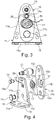
- the pivot bearing unit is in detail in the Figures 2a, 2b 3 and 4 shown.
- the pivot bearing element 10 can be designed, for example, as a metal plate. On a freely projecting section of the pivot bearing element 10, an axis of rotation of the joint 7 in the form of a pivot bearing pin 13 is protruding at right angles.
- the pivot pin 13 is on the pivot bearing element 10 preferably rigidly attached and can for example be inserted in a bore 10c and in particular riveted.
- the actuating arm 6b preferably has a bore (not shown) into which the pivot pin 13 can be inserted, in particular for play-free, pivotable attachment of the actuating arm 6b, and can be latched in the axial direction of the pivot pin, for example.
- a pivot pin can be formed on the actuating arm 6b and a receptacle for movable mounting on the pivot element 10.
- the rotary bearing unit 8 further comprises an attachment element 11, which is preferably made of e.g. right-angled sheet metal part is made.
- An attachment portion 11a of the attachment member 11 may e.g. have one or more holes 12 for attachment, in particular for screwing the rotary bearing unit 8 onto the flap element 3b.
- the attachment section 11a is arranged at right angles to an essentially plate-shaped support section 11b, on which the pivot bearing element 10 is pivotably mounted about a pivot bearing pin 14 in a plane parallel to the support section 11b.
- the pivot bearing pin 14 extends through a bore 11c on the support section 11b of the attachment element 11 and on the pivot bearing element 10 through a bore 10a which is located on a section of the pivot bearing element 10 opposite the pivot bearing pin 13.
- a plurality of cams 15 arranged in a horizontal row are formed above the pivot bearing pin 14 and can be pressed out, for example, by punching out of a plane of the support section 11b in the direction of the plate-shaped rotary bearing element 10.
- a cylindrical recess 16, into which the cams 15 can extend, is formed on a side of the rotary bearing element 10 facing the support section 11b.
- the cylindrical recess 16 is provided for a receptacle and for a rotatable mounting of an adjusting element 17.
- the adjusting element 17 has a cylindrical disk 17a.
- On one of the support sections 11b facing end face 17b is a web-shaped adjustment contour 17c.
- the web-shaped adjustment contour 17c projects axially with respect to a cylinder axis of the disk 17a on the end face 17b and extends in a spiral arc from an outer circumference of the disk 17a in the direction of a center point of the end face 17b on the cylinder axis.
- the spiral arc of the adjustment contour 17c is wound by more than one full revolution, ie an angle of more than 360 °, around the center of the disk 17a.
- the cams 15 can engage in the adjusting element 17 on the adjusting contour 17c.
- a position of the cams 15 with respect to the center point and the axis of rotation of the disk 17a can be adjusted or adjusted by rotating the adjusting element 17.
- the disk 17a preferably lies with its outer circumferential or circumferential surface in the recess 16, as a result of which a pivot angle of the pivot bearing element 10 with respect to the support section 11b about the pivot bearing pin 14 can be set. Due to the static friction contact on the outer circumferential surface of the disk 17a, a static friction force with a comparatively large leverage counteracts an automatic adjustment of the adjusting element 17, whereby an adjustment of the adjusting element 17 is advantageously secured in a self-locking manner.
- a concentric circular opening 18 is formed on the recess 16 and has a smaller diameter than the cylindrical recess 16.
- the opening 18 is for pushing through a concentric e.g. cylindrical pin 17d is provided, which protrudes on the adjusting element 17 on one end face, which is located on the adjusting element 17 opposite the end face 17b.
- a concentric e.g. cylindrical pin 17d is provided, which protrudes on the adjusting element 17 on one end face, which is located on the adjusting element 17 opposite the end face 17b.
- a tool not shown
- a blade of a screwdriver designed with which the adjusting element 17 can be adjusted.
- a cylindrical guide pin 19 is attached, which is inserted through a slot 20 on the support section 11b of the attachment element 11 above the cams 15.
- the guide pin 19 can be inserted into a bore 10d on the pivot bearing element 10 and in particular can be fastened to the pivot bearing element 10, for example by riveting.
- the guide pin is provided with a head 19a with an enlarged diameter, which prevents the guide pin 19 from being removed from the elongated hole.
- the pivot bearing element 10 is connected to the support section 11b at opposite locations with respect to the cams 15 in such a way that a distance between the pivot bearing element 10 and the support section 11b cannot increase.
- the engagement of the cams 15 in the adjustment contour 17c of the adjustment element 17 can thus advantageously be ensured.
Landscapes
- Engineering & Computer Science (AREA)
- Mechanical Engineering (AREA)
- Hinges (AREA)
Claims (13)
- Dispositif (4) pour déplacer un volet pliant (3) logé mobile sur un corps de meuble (2) et comprenant au moins deux éléments de volet (3a, 3b) reliés ensemble de manière articulée, avec une unité de force (4b) qui au moins assiste l'ouverture du volet pliant (3) par l'action d'une force par le biais d'un bras de réglage (6a) disposé, à l'état monté, sur un premier élément de volet (3a), et avec un deuxième bras de réglage (6b) relié, à l'état monté, à un deuxième élément de volet (3b), au moins l'un des deux bras de réglage (6a, 6b) étant fixé à l'élément de volet (3a, 3b) associé par le biais d'une articulation (7),
caractérisé en ce que
l'articulation (7) comprend une unité de palier pivotant (8) avec un dispositif de réglage (14, 15, 17) au moyen duquel une position d'un élément de palier pivotant (10) dudit au moins un bras de réglage (6a, 6b), par lequel passe un axe de rotation du bras de réglage (6a, 6b), peut être réglée sur l'élément de volet (3a, 3b) associé, le dispositif de réglage (14, 15, 17) comprenant un élément de réglage (17) ayant un contour de réglage en forme de spirale (17c) et étant logé rotatif sur l'unité de palier pivotant (8) pour permettre un réglage de la position d'un élément de palier pivotant (10), l'unité de palier pivotant (8) comprenant un élément de fixation (11) pour permettre une fixation dudit au moins un bras de réglage (6a, 6b) sur l'élément de volet (3a, 3b) et sur lequel l'élément de palier pivotant (10) est monté de manière réglable au moyen du dispositif de réglage (14, 15, 17), l'élément de palier pivotant (10) étant monté sur l'élément de fixation (11) de manière réglable par un mouvement en forme d'arc de cercle autour d'un axe de pivotement, l'axe de pivotement étant différent de l'axe de rotation, l'élément de réglage (17) avec le contour de réglage en forme de spirale (17c) étant en prise avec une structure d'engrènement (15) de l'élément de fixation (11), la structure d'engrènement (15) étant réalisée sous la forme d'une saillie en forme de came ayant une section circulaire ou elliptique. - Dispositif (4) selon l'une des revendications précédentes, caractérisé en ce que le contour de réglage (17 c ) est formé sur une face frontale de l'élément de réglage (17) entre deux plans parallèles placés perpendiculaires à un axe de rotation de réglage.
- Dispositif (4) selon l'une des revendications précédentes, caractérisé en ce que l'élément de réglage (17) comprend un disque (17a) sur lequel est formé le contour de réglage en forme de spirale (17c) en saillant d'une face frontale (17b) en formant une nervure.
- Dispositif (4) selon l'une des revendications précédentes, caractérisé en ce que l'élément de réglage (17) comprend un disque (17a) sur lequel est formé le contour de réglage en forme de spirale (17c) sous la forme d'un évidement en forme de rainure réalisé sur une face frontale.
- Dispositif (4) selon l'une des revendications précédentes, caractérisé en ce qu'un tenon (17d) est formé en saillant de façon centrée sur une face frontale de l'élément de réglage (17) opposée à la face frontale (17b) du contour de réglage (17c).
- Dispositif (4) selon l'une des revendications précédentes, caractérisé en ce qu'une prise pour un outil de réglage est formée sur une face frontale de l'élément de réglage (17) opposée à la face frontale (17b) du contour de réglage (17c), et en particulier sur le tenon (17d).
- Dispositif (4) selon l'une des revendications précédentes, caractérisé en ce qu'un tenon saille de façon centrée sur la face frontale (17b) de l'élément de réglage (17) sur laquelle est formé le contour de réglage (17c).
- Dispositif (4) selon l'une des revendications précédentes, caractérisé en ce qu'une position angulaire de l'élément de réglage (17) peut être bloquée par une liaison vissée entre l'élément de palier pivotant (10) et l'élément de fixation (11).
- Dispositif (4) selon l'une des revendications précédentes, caractérisé en ce qu'une ouverture de passage sans filetage de la liaison vissée est réalisée sur l'élément de palier pivotant (10) et/ou sur l'élément de fixation (11) sous la forme d'un trou oblong qui s'étend notamment dans la direction longitudinale de l'élément de palier pivotant (10) et/ou de l'élément de fixation (11).
- Dispositif (4) selon l'une des revendications précédentes, caractérisé en ce qu'une suite de plusieurs alésages pour une liaison vissée de fixation entre l'élément de palier pivotant (10) et l'élément de fixation (11) est formée sur l'élément de palier pivotant (10) et/ou sur l'élément de montage (11), lesquels alésages sont notamment munis d'un filetage intérieur adapté à une vis de fixation.
- Dispositif (4) selon l'une des revendications précédentes, caractérisé en ce que le dispositif de réglage (14, 15, 17) comprend un corps de palier qui entoure l'élément de réglage (17) perpendiculairement à l'axe de rotation de réglage, le corps de palier (10) étant prévu pour être disposé sur l'élément de palier pivotant et/ou l'élément de fixation (11).
- Dispositif (4) selon l'une des revendications précédentes, caractérisé en ce que l'élément de réglage (17) est logé dans le corps de palier de telle sorte que l'élément de réglage (17) dépasse de la surface du corps de palier au moins d'un côté (10a) de celui-ci en direction de l'axe de rotation du réglage.
- Meubles (1) avec un dispositif (4) selon l'une des revendications précédentes.
Applications Claiming Priority (1)
| Application Number | Priority Date | Filing Date | Title |
|---|---|---|---|
| DE202014102474.3U DE202014102474U1 (de) | 2014-05-27 | 2014-05-27 | Verstellbares Klappenlager |
Publications (3)
| Publication Number | Publication Date |
|---|---|
| EP2949845A2 EP2949845A2 (fr) | 2015-12-02 |
| EP2949845A3 EP2949845A3 (fr) | 2015-12-23 |
| EP2949845B1 true EP2949845B1 (fr) | 2019-12-25 |
Family
ID=53177263
Family Applications (1)
| Application Number | Title | Priority Date | Filing Date |
|---|---|---|---|
| EP15167919.8A Active EP2949845B1 (fr) | 2014-05-27 | 2015-05-18 | Articulation de volet réglable |
Country Status (2)
| Country | Link |
|---|---|
| EP (1) | EP2949845B1 (fr) |
| DE (1) | DE202014102474U1 (fr) |
Families Citing this family (3)
| Publication number | Priority date | Publication date | Assignee | Title |
|---|---|---|---|---|
| CN107747446B (zh) * | 2017-11-17 | 2023-02-03 | 广东东泰五金精密制造有限公司 | 一种用于家具上翻折叠门的活动定位结构 |
| CN107916861B (zh) * | 2017-12-15 | 2023-06-02 | 广东东泰五金精密制造有限公司 | 一种家具上翻折叠门的活动定位装配结构 |
| CN111088917A (zh) * | 2020-01-17 | 2020-05-01 | 广东星徽精密制造股份有限公司 | 一种铰链快速拆卸锁离调节装置 |
Family Cites Families (3)
| Publication number | Priority date | Publication date | Assignee | Title |
|---|---|---|---|---|
| AT409288B (de) * | 2000-02-28 | 2002-07-25 | Blum Gmbh Julius | Möbelscharnier |
| DE102007021656B4 (de) * | 2007-05-04 | 2010-12-09 | Hetal-Werke Franz Hettich Gmbh & Co. Kg | Klappenhalter für eine Möbelklappe |
| DE202010015094U1 (de) * | 2010-11-04 | 2012-02-06 | Grass Gmbh | Möbelbeschlag und Möbel |
-
2014
- 2014-05-27 DE DE202014102474.3U patent/DE202014102474U1/de not_active Expired - Lifetime
-
2015
- 2015-05-18 EP EP15167919.8A patent/EP2949845B1/fr active Active
Non-Patent Citations (1)
| Title |
|---|
| None * |
Also Published As
| Publication number | Publication date |
|---|---|
| EP2949845A2 (fr) | 2015-12-02 |
| EP2949845A3 (fr) | 2015-12-23 |
| DE202014102474U1 (de) | 2015-08-28 |
Similar Documents
| Publication | Publication Date | Title |
|---|---|---|
| EP3818225B1 (fr) | Ferrure pour meuble | |
| DE102017126367A1 (de) | Klappenbeschlag für ein Möbel, Seitenwand eines Möbelkorpus und Möbel mit einer Seitenwand | |
| EP3580420B1 (fr) | Charnière de meuble pourvue d'un élément de blocage pour un amortisseur linéaire | |
| EP2685204B1 (fr) | Dispositif de montage d'un dispositif de visée sur une arme à feu de poing | |
| EP3622153B1 (fr) | Commande de meuble à moteur | |
| EP1812674A1 (fr) | Mecanisme de reglage | |
| EP3680431B1 (fr) | Bande de recouvrement pour portes | |
| EP1893836B1 (fr) | Charnière de meuble | |
| WO2018208239A1 (fr) | Dispositif de retenue pour façade de tiroir | |
| DE102020125604A1 (de) | Kühlschrank | |
| WO2005103590A1 (fr) | Appareil menager comportant un ecran d'affichage pivotant | |
| DE102012218168B3 (de) | Glastürscharnier | |
| EP1988242B1 (fr) | Support de clapet pour clapet de meuble | |
| EP2309086A1 (fr) | Elément de retenue pour le réglage d'un couvercle de meuble | |
| EP2949845A2 (fr) | Articulation de volet réglable | |
| DE10110311C2 (de) | Scharnier mit Höhenverstellschraube | |
| EP3621484A2 (fr) | Dispositif de retenue pour façade de tiroir | |
| EP3175068B1 (fr) | Système de ferrure | |
| EP4486173B1 (fr) | Élément de meuble ou de produit électroménagé | |
| EP2149664B1 (fr) | Structure de support pour une charnière et charnière dotée d'une telle structure de support destinée à la fixation sur un vantail de porte | |
| EP2949847B1 (fr) | Levier de commande réglable | |
| EP2208843B1 (fr) | Charnière pour une porte | |
| DE202004004258U1 (de) | Scharnier und Duschabtrennung | |
| EP1662083B1 (fr) | Dispositif d'arrêt pour portes ou fenêtres | |
| EP2586946B1 (fr) | Dispositif de fixation pour une porte coulissante sur un chariot d'entraînement |
Legal Events
| Date | Code | Title | Description |
|---|---|---|---|
| PUAL | Search report despatched |
Free format text: ORIGINAL CODE: 0009013 |
|
| AK | Designated contracting states |
Kind code of ref document: A2 Designated state(s): AL AT BE BG CH CY CZ DE DK EE ES FI FR GB GR HR HU IE IS IT LI LT LU LV MC MK MT NL NO PL PT RO RS SE SI SK SM TR |
|
| AX | Request for extension of the european patent |
Extension state: BA ME |
|
| PUAI | Public reference made under article 153(3) epc to a published international application that has entered the european phase |
Free format text: ORIGINAL CODE: 0009012 |
|
| AK | Designated contracting states |
Kind code of ref document: A3 Designated state(s): AL AT BE BG CH CY CZ DE DK EE ES FI FR GB GR HR HU IE IS IT LI LT LU LV MC MK MT NL NO PL PT RO RS SE SI SK SM TR |
|
| AX | Request for extension of the european patent |
Extension state: BA ME |
|
| RIC1 | Information provided on ipc code assigned before grant |
Ipc: E05D 7/04 20060101AFI20151118BHEP Ipc: E05D 15/26 20060101ALI20151118BHEP Ipc: E05F 1/10 20060101ALI20151118BHEP |
|
| 17P | Request for examination filed |
Effective date: 20160617 |
|
| RBV | Designated contracting states (corrected) |
Designated state(s): AL AT BE BG CH CY CZ DE DK EE ES FI FR GB GR HR HU IE IS IT LI LT LU LV MC MK MT NL NO PL PT RO RS SE SI SK SM TR |
|
| STAA | Information on the status of an ep patent application or granted ep patent |
Free format text: STATUS: EXAMINATION IS IN PROGRESS |
|
| 17Q | First examination report despatched |
Effective date: 20180907 |
|
| RAP1 | Party data changed (applicant data changed or rights of an application transferred) |
Owner name: GRASS GMBH |
|
| GRAP | Despatch of communication of intention to grant a patent |
Free format text: ORIGINAL CODE: EPIDOSNIGR1 |
|
| STAA | Information on the status of an ep patent application or granted ep patent |
Free format text: STATUS: GRANT OF PATENT IS INTENDED |
|
| GRAJ | Information related to disapproval of communication of intention to grant by the applicant or resumption of examination proceedings by the epo deleted |
Free format text: ORIGINAL CODE: EPIDOSDIGR1 |
|
| STAA | Information on the status of an ep patent application or granted ep patent |
Free format text: STATUS: EXAMINATION IS IN PROGRESS |
|
| INTG | Intention to grant announced |
Effective date: 20190724 |
|
| INTC | Intention to grant announced (deleted) | ||
| GRAP | Despatch of communication of intention to grant a patent |
Free format text: ORIGINAL CODE: EPIDOSNIGR1 |
|
| STAA | Information on the status of an ep patent application or granted ep patent |
Free format text: STATUS: GRANT OF PATENT IS INTENDED |
|
| INTG | Intention to grant announced |
Effective date: 20190918 |
|
| GRAS | Grant fee paid |
Free format text: ORIGINAL CODE: EPIDOSNIGR3 |
|
| GRAA | (expected) grant |
Free format text: ORIGINAL CODE: 0009210 |
|
| STAA | Information on the status of an ep patent application or granted ep patent |
Free format text: STATUS: THE PATENT HAS BEEN GRANTED |
|
| AK | Designated contracting states |
Kind code of ref document: B1 Designated state(s): AL AT BE BG CH CY CZ DE DK EE ES FI FR GB GR HR HU IE IS IT LI LT LU LV MC MK MT NL NO PL PT RO RS SE SI SK SM TR |
|
| REG | Reference to a national code |
Ref country code: GB Ref legal event code: FG4D Free format text: NOT ENGLISH |
|
| REG | Reference to a national code |
Ref country code: CH Ref legal event code: EP |
|
| REG | Reference to a national code |
Ref country code: AT Ref legal event code: REF Ref document number: 1217298 Country of ref document: AT Kind code of ref document: T Effective date: 20200115 |
|
| REG | Reference to a national code |
Ref country code: DE Ref legal event code: R096 Ref document number: 502015011299 Country of ref document: DE |
|
| REG | Reference to a national code |
Ref country code: IE Ref legal event code: FG4D Free format text: LANGUAGE OF EP DOCUMENT: GERMAN |
|
| REG | Reference to a national code |
Ref country code: NL Ref legal event code: MP Effective date: 20191225 |
|
| PG25 | Lapsed in a contracting state [announced via postgrant information from national office to epo] |
Ref country code: SE Free format text: LAPSE BECAUSE OF FAILURE TO SUBMIT A TRANSLATION OF THE DESCRIPTION OR TO PAY THE FEE WITHIN THE PRESCRIBED TIME-LIMIT Effective date: 20191225 Ref country code: LV Free format text: LAPSE BECAUSE OF FAILURE TO SUBMIT A TRANSLATION OF THE DESCRIPTION OR TO PAY THE FEE WITHIN THE PRESCRIBED TIME-LIMIT Effective date: 20191225 Ref country code: BG Free format text: LAPSE BECAUSE OF FAILURE TO SUBMIT A TRANSLATION OF THE DESCRIPTION OR TO PAY THE FEE WITHIN THE PRESCRIBED TIME-LIMIT Effective date: 20200325 Ref country code: FI Free format text: LAPSE BECAUSE OF FAILURE TO SUBMIT A TRANSLATION OF THE DESCRIPTION OR TO PAY THE FEE WITHIN THE PRESCRIBED TIME-LIMIT Effective date: 20191225 Ref country code: NO Free format text: LAPSE BECAUSE OF FAILURE TO SUBMIT A TRANSLATION OF THE DESCRIPTION OR TO PAY THE FEE WITHIN THE PRESCRIBED TIME-LIMIT Effective date: 20200325 Ref country code: GR Free format text: LAPSE BECAUSE OF FAILURE TO SUBMIT A TRANSLATION OF THE DESCRIPTION OR TO PAY THE FEE WITHIN THE PRESCRIBED TIME-LIMIT Effective date: 20200326 Ref country code: LT Free format text: LAPSE BECAUSE OF FAILURE TO SUBMIT A TRANSLATION OF THE DESCRIPTION OR TO PAY THE FEE WITHIN THE PRESCRIBED TIME-LIMIT Effective date: 20191225 |
|
| REG | Reference to a national code |
Ref country code: LT Ref legal event code: MG4D |
|
| PG25 | Lapsed in a contracting state [announced via postgrant information from national office to epo] |
Ref country code: HR Free format text: LAPSE BECAUSE OF FAILURE TO SUBMIT A TRANSLATION OF THE DESCRIPTION OR TO PAY THE FEE WITHIN THE PRESCRIBED TIME-LIMIT Effective date: 20191225 Ref country code: RS Free format text: LAPSE BECAUSE OF FAILURE TO SUBMIT A TRANSLATION OF THE DESCRIPTION OR TO PAY THE FEE WITHIN THE PRESCRIBED TIME-LIMIT Effective date: 20191225 |
|
| PG25 | Lapsed in a contracting state [announced via postgrant information from national office to epo] |
Ref country code: AL Free format text: LAPSE BECAUSE OF FAILURE TO SUBMIT A TRANSLATION OF THE DESCRIPTION OR TO PAY THE FEE WITHIN THE PRESCRIBED TIME-LIMIT Effective date: 20191225 |
|
| PG25 | Lapsed in a contracting state [announced via postgrant information from national office to epo] |
Ref country code: CZ Free format text: LAPSE BECAUSE OF FAILURE TO SUBMIT A TRANSLATION OF THE DESCRIPTION OR TO PAY THE FEE WITHIN THE PRESCRIBED TIME-LIMIT Effective date: 20191225 Ref country code: NL Free format text: LAPSE BECAUSE OF FAILURE TO SUBMIT A TRANSLATION OF THE DESCRIPTION OR TO PAY THE FEE WITHIN THE PRESCRIBED TIME-LIMIT Effective date: 20191225 Ref country code: PT Free format text: LAPSE BECAUSE OF FAILURE TO SUBMIT A TRANSLATION OF THE DESCRIPTION OR TO PAY THE FEE WITHIN THE PRESCRIBED TIME-LIMIT Effective date: 20200520 Ref country code: RO Free format text: LAPSE BECAUSE OF FAILURE TO SUBMIT A TRANSLATION OF THE DESCRIPTION OR TO PAY THE FEE WITHIN THE PRESCRIBED TIME-LIMIT Effective date: 20191225 Ref country code: EE Free format text: LAPSE BECAUSE OF FAILURE TO SUBMIT A TRANSLATION OF THE DESCRIPTION OR TO PAY THE FEE WITHIN THE PRESCRIBED TIME-LIMIT Effective date: 20191225 |
|
| PG25 | Lapsed in a contracting state [announced via postgrant information from national office to epo] |
Ref country code: IS Free format text: LAPSE BECAUSE OF FAILURE TO SUBMIT A TRANSLATION OF THE DESCRIPTION OR TO PAY THE FEE WITHIN THE PRESCRIBED TIME-LIMIT Effective date: 20200425 Ref country code: SM Free format text: LAPSE BECAUSE OF FAILURE TO SUBMIT A TRANSLATION OF THE DESCRIPTION OR TO PAY THE FEE WITHIN THE PRESCRIBED TIME-LIMIT Effective date: 20191225 Ref country code: SK Free format text: LAPSE BECAUSE OF FAILURE TO SUBMIT A TRANSLATION OF THE DESCRIPTION OR TO PAY THE FEE WITHIN THE PRESCRIBED TIME-LIMIT Effective date: 20191225 |
|
| REG | Reference to a national code |
Ref country code: DE Ref legal event code: R097 Ref document number: 502015011299 Country of ref document: DE |
|
| PG25 | Lapsed in a contracting state [announced via postgrant information from national office to epo] |
Ref country code: ES Free format text: LAPSE BECAUSE OF FAILURE TO SUBMIT A TRANSLATION OF THE DESCRIPTION OR TO PAY THE FEE WITHIN THE PRESCRIBED TIME-LIMIT Effective date: 20191225 Ref country code: DK Free format text: LAPSE BECAUSE OF FAILURE TO SUBMIT A TRANSLATION OF THE DESCRIPTION OR TO PAY THE FEE WITHIN THE PRESCRIBED TIME-LIMIT Effective date: 20191225 |
|
| PLBE | No opposition filed within time limit |
Free format text: ORIGINAL CODE: 0009261 |
|
| STAA | Information on the status of an ep patent application or granted ep patent |
Free format text: STATUS: NO OPPOSITION FILED WITHIN TIME LIMIT |
|
| PG25 | Lapsed in a contracting state [announced via postgrant information from national office to epo] |
Ref country code: SI Free format text: LAPSE BECAUSE OF FAILURE TO SUBMIT A TRANSLATION OF THE DESCRIPTION OR TO PAY THE FEE WITHIN THE PRESCRIBED TIME-LIMIT Effective date: 20191225 |
|
| 26N | No opposition filed |
Effective date: 20200928 |
|
| PG25 | Lapsed in a contracting state [announced via postgrant information from national office to epo] |
Ref country code: IT Free format text: LAPSE BECAUSE OF FAILURE TO SUBMIT A TRANSLATION OF THE DESCRIPTION OR TO PAY THE FEE WITHIN THE PRESCRIBED TIME-LIMIT Effective date: 20191225 Ref country code: LI Free format text: LAPSE BECAUSE OF NON-PAYMENT OF DUE FEES Effective date: 20200531 Ref country code: CH Free format text: LAPSE BECAUSE OF NON-PAYMENT OF DUE FEES Effective date: 20200531 Ref country code: MC Free format text: LAPSE BECAUSE OF FAILURE TO SUBMIT A TRANSLATION OF THE DESCRIPTION OR TO PAY THE FEE WITHIN THE PRESCRIBED TIME-LIMIT Effective date: 20191225 |
|
| PG25 | Lapsed in a contracting state [announced via postgrant information from national office to epo] |
Ref country code: PL Free format text: LAPSE BECAUSE OF FAILURE TO SUBMIT A TRANSLATION OF THE DESCRIPTION OR TO PAY THE FEE WITHIN THE PRESCRIBED TIME-LIMIT Effective date: 20191225 |
|
| REG | Reference to a national code |
Ref country code: BE Ref legal event code: MM Effective date: 20200531 |
|
| GBPC | Gb: european patent ceased through non-payment of renewal fee |
Effective date: 20200518 |
|
| PG25 | Lapsed in a contracting state [announced via postgrant information from national office to epo] |
Ref country code: LU Free format text: LAPSE BECAUSE OF NON-PAYMENT OF DUE FEES Effective date: 20200518 |
|
| PG25 | Lapsed in a contracting state [announced via postgrant information from national office to epo] |
Ref country code: FR Free format text: LAPSE BECAUSE OF NON-PAYMENT OF DUE FEES Effective date: 20200531 Ref country code: IE Free format text: LAPSE BECAUSE OF NON-PAYMENT OF DUE FEES Effective date: 20200518 Ref country code: GB Free format text: LAPSE BECAUSE OF NON-PAYMENT OF DUE FEES Effective date: 20200518 |
|
| PG25 | Lapsed in a contracting state [announced via postgrant information from national office to epo] |
Ref country code: BE Free format text: LAPSE BECAUSE OF NON-PAYMENT OF DUE FEES Effective date: 20200531 |
|
| PG25 | Lapsed in a contracting state [announced via postgrant information from national office to epo] |
Ref country code: TR Free format text: LAPSE BECAUSE OF FAILURE TO SUBMIT A TRANSLATION OF THE DESCRIPTION OR TO PAY THE FEE WITHIN THE PRESCRIBED TIME-LIMIT Effective date: 20191225 Ref country code: MT Free format text: LAPSE BECAUSE OF FAILURE TO SUBMIT A TRANSLATION OF THE DESCRIPTION OR TO PAY THE FEE WITHIN THE PRESCRIBED TIME-LIMIT Effective date: 20191225 Ref country code: CY Free format text: LAPSE BECAUSE OF FAILURE TO SUBMIT A TRANSLATION OF THE DESCRIPTION OR TO PAY THE FEE WITHIN THE PRESCRIBED TIME-LIMIT Effective date: 20191225 |
|
| PG25 | Lapsed in a contracting state [announced via postgrant information from national office to epo] |
Ref country code: MK Free format text: LAPSE BECAUSE OF FAILURE TO SUBMIT A TRANSLATION OF THE DESCRIPTION OR TO PAY THE FEE WITHIN THE PRESCRIBED TIME-LIMIT Effective date: 20191225 |
|
| REG | Reference to a national code |
Ref country code: DE Ref legal event code: R082 Ref document number: 502015011299 Country of ref document: DE Representative=s name: RAVENSPAT PATENTANWAELTE PARTNERSCHAFT MBB, DE |
|
| PGFP | Annual fee paid to national office [announced via postgrant information from national office to epo] |
Ref country code: DE Payment date: 20250523 Year of fee payment: 11 |
|
| PGFP | Annual fee paid to national office [announced via postgrant information from national office to epo] |
Ref country code: AT Payment date: 20250526 Year of fee payment: 11 |