EP2949847B1 - Levier de commande réglable - Google Patents
Levier de commande réglable Download PDFInfo
- Publication number
- EP2949847B1 EP2949847B1 EP15167918.0A EP15167918A EP2949847B1 EP 2949847 B1 EP2949847 B1 EP 2949847B1 EP 15167918 A EP15167918 A EP 15167918A EP 2949847 B1 EP2949847 B1 EP 2949847B1
- Authority
- EP
- European Patent Office
- Prior art keywords
- actuating arm
- adjustment
- end side
- contour
- adjusting
- Prior art date
- Legal status (The legal status is an assumption and is not a legal conclusion. Google has not performed a legal analysis and makes no representation as to the accuracy of the status listed.)
- Active
Links
Images


Classifications
-
- E—FIXED CONSTRUCTIONS
- E05—LOCKS; KEYS; WINDOW OR DOOR FITTINGS; SAFES
- E05D—HINGES OR SUSPENSION DEVICES FOR DOORS, WINDOWS OR WINGS
- E05D15/00—Suspension arrangements for wings
- E05D15/26—Suspension arrangements for wings for folding wings
- E05D15/262—Suspension arrangements for wings for folding wings folding vertically
-
- E—FIXED CONSTRUCTIONS
- E05—LOCKS; KEYS; WINDOW OR DOOR FITTINGS; SAFES
- E05F—DEVICES FOR MOVING WINGS INTO OPEN OR CLOSED POSITION; CHECKS FOR WINGS; WING FITTINGS NOT OTHERWISE PROVIDED FOR, CONCERNED WITH THE FUNCTIONING OF THE WING
- E05F1/00—Closers or openers for wings, not otherwise provided for in this subclass
- E05F1/08—Closers or openers for wings, not otherwise provided for in this subclass spring-actuated, e.g. for horizontally sliding wings
- E05F1/10—Closers or openers for wings, not otherwise provided for in this subclass spring-actuated, e.g. for horizontally sliding wings for swinging wings, e.g. counterbalance
- E05F1/1041—Closers or openers for wings, not otherwise provided for in this subclass spring-actuated, e.g. for horizontally sliding wings for swinging wings, e.g. counterbalance with a coil spring perpendicular to the pivot axis
- E05F1/105—Closers or openers for wings, not otherwise provided for in this subclass spring-actuated, e.g. for horizontally sliding wings for swinging wings, e.g. counterbalance with a coil spring perpendicular to the pivot axis with a compression spring
- E05F1/1058—Closers or openers for wings, not otherwise provided for in this subclass spring-actuated, e.g. for horizontally sliding wings for swinging wings, e.g. counterbalance with a coil spring perpendicular to the pivot axis with a compression spring for counterbalancing
-
- E—FIXED CONSTRUCTIONS
- E05—LOCKS; KEYS; WINDOW OR DOOR FITTINGS; SAFES
- E05Y—INDEXING SCHEME ASSOCIATED WITH SUBCLASSES E05D AND E05F, RELATING TO CONSTRUCTION ELEMENTS, ELECTRIC CONTROL, POWER SUPPLY, POWER SIGNAL OR TRANSMISSION, USER INTERFACES, MOUNTING OR COUPLING, DETAILS, ACCESSORIES, AUXILIARY OPERATIONS NOT OTHERWISE PROVIDED FOR, APPLICATION THEREOF
- E05Y2600/00—Mounting or coupling arrangements for elements provided for in this subclass
- E05Y2600/10—Adjustable
- E05Y2600/30—Adjustment motion
- E05Y2600/33—Stepwise motion
-
- E—FIXED CONSTRUCTIONS
- E05—LOCKS; KEYS; WINDOW OR DOOR FITTINGS; SAFES
- E05Y—INDEXING SCHEME ASSOCIATED WITH SUBCLASSES E05D AND E05F, RELATING TO CONSTRUCTION ELEMENTS, ELECTRIC CONTROL, POWER SUPPLY, POWER SIGNAL OR TRANSMISSION, USER INTERFACES, MOUNTING OR COUPLING, DETAILS, ACCESSORIES, AUXILIARY OPERATIONS NOT OTHERWISE PROVIDED FOR, APPLICATION THEREOF
- E05Y2800/00—Details, accessories and auxiliary operations not otherwise provided for
- E05Y2800/37—Length, width or depth adjustment
-
- E—FIXED CONSTRUCTIONS
- E05—LOCKS; KEYS; WINDOW OR DOOR FITTINGS; SAFES
- E05Y—INDEXING SCHEME ASSOCIATED WITH SUBCLASSES E05D AND E05F, RELATING TO CONSTRUCTION ELEMENTS, ELECTRIC CONTROL, POWER SUPPLY, POWER SIGNAL OR TRANSMISSION, USER INTERFACES, MOUNTING OR COUPLING, DETAILS, ACCESSORIES, AUXILIARY OPERATIONS NOT OTHERWISE PROVIDED FOR, APPLICATION THEREOF
- E05Y2900/00—Application of doors, windows, wings or fittings thereof
- E05Y2900/20—Application of doors, windows, wings or fittings thereof for furniture, e.g. cabinets
Definitions
- the invention relates to a device for moving a folding flap which is movably received on a furniture body according to the preamble of claim 1 and to a piece of furniture.
- the folding flap consists of at least two hinged flap elements.
- Such a device is regularly equipped with a power unit which at least supports the opening of the folding flap by the action of force via an actuating arm arranged on a first flap element in the assembled state.
- a second actuating arm is often provided for a folding flap, which in the assembled state is connected to a second flap element in order to avoid, for example, uncontrolled, in particular oscillating, movements of the second flap element.
- the invention is based on the object of providing a device for moving a folding flap, the adjustability of which is improved.
- the invention is based on a device for moving a folding flap movably received on a furniture carcass consisting of at least two articulated flap elements with a force unit which at least supports the opening of the folding flap through the action of force via an actuating arm arranged on a first flap element in the assembled state.
- the device is equipped with a second actuating arm which, in the assembled state, is connected to a second flap element.
- at least one of the two actuating arms comprises two actuating arm sections which are connected to one another via an adjusting device.
- the essence of the invention is that an adjusting element with a spiral-shaped adjusting contour is rotatably mounted on a first actuating arm section, an engagement structure being formed on a second actuating arm section which is designed to engage the adjusting contour.
- the adjustment contour can, for example, be spiral-shaped in such a way that successive engagement positions on the adjustment contour corresponding to a direction of rotation have an increasing distance from a predetermined axis of rotation, the distance being able to increase proportionally, for example, to an increasing angle of rotation in the direction of rotation.
- a reference or center point of the spiral adjustment contour in particular a starting point of the spiral shape, is preferably arranged in the axis of rotation of the adjustment element.
- the engagement structure can intervene in such a way that a section of the engagement structure rests point-like and / or linearly against a section of the adjustment contour.
- the engagement structure can be designed in such a way that it is flat on the spiral adjustment structure, for example via a Angular section extends around an axis of rotation of the adjusting element rests. Laterally delimiting surface areas of the adjustment contour are preferably provided for supporting the engagement structure.
- the adjusting device can be designed to be self-locking relatively easily, with a load on the actuating arm being able to prevent unintentional rotation of the adjusting element both when a setting is changed on the actuating arm and after a setting has been fixed.
- the adjusting element and in particular an axis of rotation of the adjusting element is preferably mounted in a stationary manner with respect to the first actuating arm section.
- the engagement structure is preferably designed to be stationary on the second actuating arm section.
- the adjustment contour is preferably formed on an end face of the adjustment element between two parallel planes which are perpendicular to an adjustment axis of rotation.
- the spiral adjustment contour can be designed in the form of a helical ramp which, for example, extends axially with decreasing distance from the axis of rotation of the adjustment element and is designed to run around the axis of rotation. In this way, for example, a comparatively large contact or support surface can be provided between the engagement structure and the adjustment element.
- An outer plane can provide a friction surface against which a pressure surface for fixing an angular position of the adjusting element can be pressed.
- the pressure surface can, for example, be a side surface of one of the actuating arm sections, which can be attached facing the outer plane of the adjusting element. For example, by tightening a screw with which the two actuating arm sections can be connected, the Side surface of the actuating arm section be pressed against the outer plane in sections.
- the pressure surface can be a surface area of the engagement structure.
- the adjustment element can comprise a preferably circular disk on which the spiral adjustment contour is designed to protrude in the form of a web on one end face.
- the adjustment element can be designed comparatively easily with an adjustment contour that can be adjusted via more than one rotation.
- the end face with the web-shaped adjusting contour is preferably a circular disk-shaped, flat surface which deviates from a flat design only in the area of the adjusting contour.
- the adjustment device can be designed to be comparatively space-saving.
- the center of the spiral is preferably designed concentrically to the circular disk-shaped end face.
- the adjusting element can be adjusted at least approximately with the same torque from different starting positions.
- the circular disk-shaped end face can, for example, be an end face of a cylindrical disk, the outer surface of which can advantageously be used for a rotatable mounting. This means that an additional structure for a rotatable bearing such as a bearing pin can be dispensed with.
- the engagement structure on the second actuating arm section can interact with an adjusting contour section of different inclination.
- the engagement structure on the second actuating arm section is preferably a pin or a cam-shaped or pin-shaped projection with a circular or elliptical cross section.
- the adjusting element can comprise a disk, on which the spiral adjustment contour is designed as a groove-shaped recess on one end face.
- the engagement structure can also be designed as a pin or knob-shaped projection with a circular or elliptical cross-section.
- the adjusting element can be designed to be comparatively stable and with comparatively little play for the engagement structure.
- a larger contact surface for fixing the adjusting element can advantageously be provided on the front side with the adjusting contour.
- a preferred embodiment of the invention consists in that a bearing journal is formed in particular protruding centrally on an end face of the adjusting element which is arranged opposite to the end face of the adjusting contour.
- the adjusting element can thus be mounted in a comparatively stable manner. If a bearing journal is only formed on the end face that is opposite the side with the adjustment contour on the adjustment element, it can advantageously be avoided that the spiral adjustment contour is shortened in favor of a bearing journal on the same end face and thereby an adjustment range of the adjustment element is reduced.
- the bearing pin can be designed to protrude to a length such that the bearing pin extends into an opening or recess of an actuating arm section and, in particular, extends through it.
- the bearing pin preferably has a smaller diameter than the disk so that a protruding edge section of the end face with the bearing pin is available as a pressure surface, for example for fixing an angular position of the adjusting element. Adjustability of the adjusting element can also be made easier in this case.
- an engagement for an adjusting tool is formed on an end face of the adjusting element which is opposite to the end face of the adjusting contour, and in particular on the bearing journal.
- Adjusting device thus has an advantageously simple structure.
- a bearing pin can protrude centrally from the end face on the end face of the adjustment element on which the adjustment contour is formed.
- the adjustment element can thus be mounted so that it can rotate symmetrically, for example, in order to reduce wear-increasing forces.
- An angular position of the adjusting element can preferably be fixed with a screw connection of the two adjusting arm sections, which is preferably arranged next to the adjusting element.
- the screw connection is preferably provided to bring a surface section of an element of the actuating arm into frictional contact with the adjusting element in such a way that the adjusting element can no longer be rotated.
- screw connections can also be provided for this purpose.
- an in particular threadless push-through opening of the screw connection is formed as an elongated hole on one of the actuating arm sections, which in particular extends in the longitudinal direction of the second actuating arm.
- the elongated hole is designed with a length such that a screw for fixing the adjusting device in the elongated hole is displaceably positioned, ie does not strike the elongated hole when the adjusting element is overturned in one direction of rotation along the adjusting contour, ie when the adjusting element continues is rotated when the adjustment contour extends in the direction of the direction of rotation.
- a number of several bores for at least one screw connection of the actuating arm section are formed on one of the actuating arm sections, which are in particular provided with an internal thread adapted to at least one fixing screw.
- the adjacent bores for screwing in the fixing screw are preferably arranged in a longitudinal direction of the actuating arm at a distance, for example a maximum adjustment path of the adjusting element and in particular a double maximum adjustment path.
- the arrangement of the bores for screwing in the fixing screw enables a coarse adjustment of the actuating arm, which can be coordinated with the adjustment device by turning the adjustment element for a fine adjustment.
- the adjusting device can comprise a bearing body which surrounds the adjusting element perpendicular to the adjusting axis of rotation, the bearing body being provided for arrangement between the actuating arm sections.
- the bearing body can advantageously contribute to the fixing or also to the rough positioning of the adjusting element.
- the adjustment device and the actuating arm can be designed to be more stable because not only the adjusting element provides support points between the two actuating arm sections.
- the adjusting element can be mounted in the bearing body in such a way that the adjusting element protrudes in the direction of the adjusting axis of rotation on at least one side of the bearing body beyond its surface.
- the adjusting element overall with its end faces, can advantageously be clamped between the bearing body and, for example, one of the actuating arm sections for fixing purposes.
- the adjusting arm sections can be adjusted with respect to one another with the adjusting device along a straight longitudinal axis of the adjusting arm. Due to the simple and manageable effect of a change in length, there is a Adjusting an actuator arm made easier.
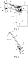
- FIG. 1 an embodiment of a piece of furniture according to the invention is shown. It is in the Figure 1 Part of a furniture compartment 2 of the furniture 1 is shown on which a multi-part furniture flap 3 with an adjusting device 4 is attached in order to movably attach the furniture flap to the furniture compartment 2 for opening or closing.
- the furniture flap 3 is designed in two parts and comprises a first flap element 3a and a second flap element 3b.
- the adjusting device 4 comprises a mounting element 4a and a first adjusting arm 6a and a second adjusting arm 6b, the two adjusting arms 6a and 6b being pivotably mounted on the mounting element 4a. Furthermore, an energy store 4b is attached to the mounting element 4a, which via a lever mechanism For example, forces can be transmitted to the actuating arm 6a.
- the mounting element 4a is attached to a side wall 2c of the furniture compartment 2 near a furniture ceiling 2a and, for example, screwed on.
- the first actuating arm 6a is firmly connected to the upper flap element 3a, the actuating arm 6a preferably being designed to transfer weight forces of the two furniture panels 3a and 3b and the hinge 5 to the mounting element 4a.
- the second actuating arm 6b is movably connected to the second flap element 3b via a pivot bearing 7.
- the actuating arm 6b is provided to guide the second flap element 3b into a predetermined closed position when it is closed and to hold it there.
- Another task of the actuating arm 6b is to avoid uncontrolled swinging of the flap element 3b on the flap element 3a when the furniture flap 3 is opened, especially when the second flap element 3b is freely pivotable, i.e. without the action of a damping torque by the hinge 5 with the upper flap element 3a is connected.
- the actuating arm 6b is designed and in particular adjustable in such a way that the second flap element 3b can repeatably reach a predetermined closed position and movement guidance by the actuating arm 6b can be readjusted if necessary.
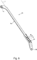
- the actuating arm 6b of the first embodiment of a device according to the invention is in the Figures 2 and 3 shown.
- the actuating arm 6b is composed of a first actuating arm section 8b and a second actuating arm section 8a, a total length of the actuating arm 6b being achieved by connecting the actuating arm sections 8a and 8b.
- the second actuating arm section 8 a has a free-standing, curved end region a bore 8 c which is provided for a rotatable attachment of the actuating arm section 8 a with a cylindrical spring sleeve 10 on the pivot bearing 7.
- On the first actuating arm section 8b is a bore 8d on one formed angled end region, which is provided for a pivotable connection of the actuating arm 6b on the mounting element 4a.
- a recess 11 is formed on the first actuating arm section 8b, into which an end section of the second actuating arm section 8a, on which a bore 9a is formed, can be inserted.
- the recess 11 is adapted to a cross section of the actuating arm section 8a in such a way that the actuating arm section 8a can be inserted preferably flush with a surface area 12 of the actuating arm section 8b and is displaceable in the recess 11 parallel to a longitudinal axis L of the actuating arm section 8b.
- the actuating arm section 8a is at least partially positively connected to the actuating arm section 8b in order to transfer actuating forces from the mounting element 4a to the flap element 3b.
- a screw 13 is provided which extends from one in the view of Figure 3
- the non-visible side of the actuating arm section 8b which is located opposite the surface section 12 on the actuating arm section 8b, can be inserted through a bore 9b in the form of an elongated hole and screwed into the bore 9a.
- a row of cam-shaped projections 14 are formed on the actuating arm section 8a along a longitudinal axis of the actuating arm section 8a, which can be pressed out, for example, by punching into the side surface 15 on a side opposite the side surface 15.
- the projections 14 are provided to engage in an adjusting element 16 in the area of a spiral-shaped adjusting contour 17 which protrudes in the form of a web on a circular end face of the adjusting element 16.
- the adjustment element 16 with the spiral adjustment contour 17 is mounted in an essentially circular recess 18, in which the recess 11 on the actuating arm section 8b is additionally deepened. Starting from a center point of the recess 18, the recess 18 is in the direction of the longitudinal axis expanded by a bulge 18a in order to provide the projections 14 with an additional movement space when the adjustment element 16 is adjusted.
- the actuating arm section 9a rests loosely or loosely on the adjusting element 16.
- the web-shaped adjusting contour 17 can protrude into the area of the recess 11 at a height that can be reduced by tightening the screw 13, preferably such that the end section of the actuating arm section 8a is embedded in the recess 11.
- a surface section of the actuating arm section 8a facing the adjusting element 16, on which the cam-shaped projections 14 are formed can fix the adjusting element 16 to the adjusting contour 17 by frictional engagement.
- the cam-shaped projections 14 rest laterally on the web-shaped adjusting contour 17, so that they can be supported on the web-shaped adjusting contour 17 in the direction of the longitudinal axis.
- the adjusting element 16 When the screw 13 is loosened, the adjusting element 16 can be rotated within the recess 18 around the center point 16a of the adjusting element 16 and thereby a region of the web-shaped adjusting contour 17 can be adjusted to support the cam-shaped projections 14. As a result, one of several different positions of the actuating arm section 8 a relative to the actuating arm section 8 b along the longitudinal axis L can be selected continuously, which can be fixed by tightening the screw 13.
- a circular perforated opening 19 is formed on the recess 18, through which the adjusting element 16 can be reached from the outside in an assembled state of the actuating arm 6b.
- a slot-shaped engagement can be formed with which the adjusting element 16 with the aid of a screwdriver is adjustable.
- connection of the actuating arm sections 8a and 8b in the recess 11 of the first actuating arm section 8b offers the advantage that bending forces on the actuating arm 6b are kept away from the actuating element 16 and the screw 13. This advantageously prevents the adjusting element 16 and the screw 13 from being damaged by, for example, shear forces.
- the actuating arm 6b has a first actuating arm section 8b and a separate second actuating arm section 8a.
- a recess 11 is formed on the actuating arm section 8b, which is adapted to a e.g. rectangular cross section of a straight end section of the actuating arm section 8a in order to connect the actuating arm section 8a to the actuating arm section 8b at least partially in a form-fitting manner. Bending loads at the connection of the actuating arm sections 8a and 8b can be transmitted along a longitudinal axis L through the recess 11, which is adapted to the actuating arm section 8a in a form-fitting manner, whereby an increased stability of the actuating arm 6b can be achieved.
- a plurality of bores 9b are formed on the actuating arm section 8b in the region of the recess 11, each bore preferably being provided with an internal thread into which a fixing screw 13 can be screwed.
- the fixing screw 16 has a length such that the fixing screw 13 can be tightened in one of the bores 9b on the actuating arm section 8b when the fixing screw 13 is pushed through a bore 9c of a clamping plate 20 and through a bore 9a on the straight end section of the actuating arm section 8a.
- the clamping plate 20 is also designed to receive the adjusting element 16, which extends with a cylindrical projection 16b through an opening 19 of the clamping plate 20.
- the cylindrical projection 16b and the Opening 19 for a stationary, rotatable mounting of the adjusting element 16 is formed between the clamping plate 20 and the actuating arm section 8 a when the clamping plate 20 is loosely connected to the fixing screw 13 on the actuating arm section 8 b.
- the fixing screw 13 By tightening the fixing screw 13, the adjusting element 16 is clamped between the clamping plate 20 and the actuating arm section 8a and is frictionally locked against changes in a position, in particular a rotational position.
- the actuating element 16 On a side facing the actuating arm section 8a, the actuating element 16 has a spiral-shaped adjusting contour 17 which, for example, like that in FIG Figure 3 shown can be designed web-shaped.
- Cam-shaped projections 14 are formed as an engagement structure next to the bore 9a on the actuating arm section 8a along a longitudinal axis L '.
- the cam-shaped projections are provided for engagement in the adjustment contour 17 of the adjustment element 16 when the actuating arm 6b, as for example in FIG Figure 6 shown is composed.
- the bore 9a is formed at least in the direction of the longitudinal axis L 'with a diameter that comprises a diameter of the fixing screw 13 and preferably an adjustment path around which the projections 14 can be displaced upon engagement with the adjusting element 16.
Landscapes
- Engineering & Computer Science (AREA)
- Mechanical Engineering (AREA)
- Chairs For Special Purposes, Such As Reclining Chairs (AREA)
- Pivots And Pivotal Connections (AREA)
Claims (14)
- Dispositif (4) destiné à déplacer un rabat (3) reçu de manière mobile sur un corps de meuble (2) et pourvu d'au moins deux éléments de rabat (3a, 3b) reliés de manière articulée, ledit dispositif comprenant une unité de force (4b) qui contribue au moins à l'ouverture du rabat par l'action d'une force par le biais d'un premier bras d'actionnement (6a) du dispositif qui est disposé sur un premier élément de rabat (3a) à l'état monté et un deuxième bras d'actionnement (6b) qui est relié à un deuxième élément de rabat (3b) à l'état monté, l'un au moins des deux bras d'actionnement (6a, 6b) comprenant deux portions de bras d'actionnement (8a, 8b) qui sont reliées l'une à l'autre par un mécanisme de réglage (14, 16),
caractérisé en ce qu'un élément de réglage (16) pourvu d'un contour de réglage en spirale (17) est monté à rotation sur la première portion de bras d'actionnement (8b) et en ce qu'une structure d'engagement (14), qui est conçue pour s'engager dans le contour de réglage (17), est formée sur la deuxième portion de bras d'actionnement (8a) . - Dispositif (4) selon la revendication 1, caractérisé en ce que le contour de réglage (17) est formé sur un côté frontal de l'élément de réglage (16) entre deux plans parallèles qui sont perpendiculaires à un axe de rotation et de réglage.
- Dispositif (4) selon l'une des revendications précédentes, caractérisé en ce que l'élément de réglage (16) comprend un disque sur lequel le contour de réglage en spirale (17) est formé en saillie en forme de nervure sur un côté frontal.
- Dispositif (4) selon la revendication 2 ou 3, caractérisé en ce que l'élément de réglage (16) comprend un disque sur lequel le contour de réglage en spirale (17) est conçu comme un creux en forme de rainure sur un côté frontal.
- Dispositif (4) selon l'une des revendications 2 à 4, caractérisé en ce qu'un tourillon (16b) est formé en saillie au centre sur un côté frontal de l'élément de réglage (16), qui est disposé en regard du côté frontal du contour de réglage (17).
- Dispositif (4) selon l'une des revendications 2 à 5, caractérisé en ce qu'un engagement destiné à un outil de réglage est formé sur un côté frontal de l'élément de réglage (16) qui est opposé au côté frontal du contour de réglage (17), et en particulier sur le tourillon (16b).
- Dispositif (4) selon l'une des revendications 2 à 6, caractérisé en ce que, sur le côté frontal de l'élément de réglage (16) où le contour de réglage (17) est formé, un tourillon fait saillie du côté frontal au centre.
- Dispositif (4) selon l'une des revendications précédentes, caractérisé en ce qu'une position angulaire de l'élément de réglage (16) peut être fixée par une liaison par vissage (9a, 9b, 9c, 13) des deux portions de bras d'actionnement (8a, 8b).
- Dispositif (4) selon l'une des revendications précédentes, caractérisé en ce qu'une ouverture d'enfichage traversante sans filetage (9a, 9b, 9c) de la liaison par vissage (9a, 9b, 9c, 13) sur l'une des portions de bras d'actionnement (8a, 8b) est ménagée sous la forme d'un trou oblong qui s'étend notamment dans une direction longitudinale du bras d'actionnement correspondant (6a, 6b).
- Dispositif (4) selon l'une des revendications précédentes, caractérisé en ce qu'une série de plusieurs alésages (9b), qui sont notamment pourvus d'un filetage intérieur adapté à la vis de fixation (13), sont ménagés sur l'une des portions de bras d'actionnement (8a, 8b) à destination d'au moins une liaison par vissage (9a, 9b, 9c, 13) des portions de bras d'actionnement (8a, 8b).
- Dispositif (4) selon l'une des revendications précédentes, caractérisé en ce que le mécanisme de réglage (14, 16) comprend un corps de palier (8b, 20) qui entoure l'élément de réglage (16) perpendiculairement à l'axe de rotation et de réglage, le corps de palier étant prévu pour être disposé sur les portions de bras d'actionnement (8a, 8b).
- Dispositif (4) selon la revendication 11, caractérisé en ce que l'élément de réglage (16) est logé dans le corps de palier (8b, 20) de telle sorte que l'élément de réglage (16) fait saillie de la surface du corps de palier (20) sur au moins un côté de celui-ci en direction de l'axe de rotation et de réglage.
- Dispositif (4) selon l'une des revendications précédentes, caractérisé en ce que les portions de bras d'actionnement (8a, 8b) sont réglables au moyen du mécanisme de réglage (14, 16) le long d'un axe longitudinal rectiligne L du bras d'actionnement (6a, 6b) .
- Meuble (1) comprenant un dispositif (4) selon l'une des revendications précédentes.
Applications Claiming Priority (1)
| Application Number | Priority Date | Filing Date | Title |
|---|---|---|---|
| DE202014102477.8U DE202014102477U1 (de) | 2014-05-27 | 2014-05-27 | Verstellbarer Steuerhebel |
Publications (2)
| Publication Number | Publication Date |
|---|---|
| EP2949847A1 EP2949847A1 (fr) | 2015-12-02 |
| EP2949847B1 true EP2949847B1 (fr) | 2021-09-01 |
Family
ID=53177262
Family Applications (1)
| Application Number | Title | Priority Date | Filing Date |
|---|---|---|---|
| EP15167918.0A Active EP2949847B1 (fr) | 2014-05-27 | 2015-05-18 | Levier de commande réglable |
Country Status (2)
| Country | Link |
|---|---|
| EP (1) | EP2949847B1 (fr) |
| DE (1) | DE202014102477U1 (fr) |
Families Citing this family (2)
| Publication number | Priority date | Publication date | Assignee | Title |
|---|---|---|---|---|
| ES2959593T3 (es) | 2017-05-15 | 2024-02-27 | Samet Kalip Ve Madeni Esya San Ve Tic A S | Cojinete de tapa con una ayuda de ajuste |
| WO2018212724A1 (fr) * | 2017-05-15 | 2018-11-22 | Samet Kalip Ve Madeni Esya San. Ve Tic. A. S. | Bras de commande réglable en longueur |
Family Cites Families (6)
| Publication number | Priority date | Publication date | Assignee | Title |
|---|---|---|---|---|
| DE9109033U1 (de) * | 1991-07-22 | 1991-09-12 | Heinrich Brinkmann GmbH & Co KG, 4520 Melle | Parallelführungsbeschlag für Türen |
| AT1214U1 (de) * | 1995-12-18 | 1996-12-27 | Blum Gmbh Julius | Scharnier |
| AT407277B (de) * | 1998-08-11 | 2001-02-26 | Blum Gmbh Julius | Scharnier |
| AT414257B (de) * | 2004-10-12 | 2006-10-15 | Blum Gmbh Julius | Halte- und einstellvorrichtung für bewegliche möbelteile |
| AT501396B1 (de) * | 2004-10-28 | 2007-10-15 | Blum Gmbh Julius | Falttürenscharnier |
| ITMI20050181A1 (it) * | 2005-02-09 | 2006-08-10 | Effegi Brevetti Srl | Dispositivo di apertura-chiusura di un'anta a ribalta di un mobile |
-
2014
- 2014-05-27 DE DE202014102477.8U patent/DE202014102477U1/de not_active Expired - Lifetime
-
2015
- 2015-05-18 EP EP15167918.0A patent/EP2949847B1/fr active Active
Also Published As
| Publication number | Publication date |
|---|---|
| DE202014102477U1 (de) | 2015-08-28 |
| EP2949847A1 (fr) | 2015-12-02 |
Similar Documents
| Publication | Publication Date | Title |
|---|---|---|
| EP2527576B1 (fr) | Dispositif de déplacement pour éléments de séparation maintenus de manière rotative et élément de mobilier | |
| EP3177839B1 (fr) | Boulon pour serrer des pièces placées l'une contre l'autre | |
| EP3622153B1 (fr) | Commande de meuble à moteur | |
| EP0774324A2 (fr) | Pince avec deux bras | |
| DE102009025890A1 (de) | Vorrichtung zur Befestigung einer Frontblende an einer Seitenzarge eines beweglichen Möbelteils eines Möbels, Schubkasten und Möbel | |
| EP3088645B1 (fr) | Dispositif de liaison pour une porte coulissante | |
| AT6962U1 (de) | Scharnier | |
| EP2265784B1 (fr) | Dispositif de réglage pour meubles | |
| EP2217409B1 (fr) | Machine-outil manuelle avec poignée | |
| EP3359826B1 (fr) | Ferrure de meuble | |
| EP3808997B1 (fr) | Dispositif goujon | |
| EP0708219A1 (fr) | Ferrure ou similaire, de préférence partie charnière, avec dispositif de fixation | |
| EP2949847B1 (fr) | Levier de commande réglable | |
| DE10006587C2 (de) | Verstellbares Scharnier | |
| EP2949845B1 (fr) | Articulation de volet réglable | |
| DE4436199C1 (de) | Radiusbetätiger für Sicherheitsschalter | |
| DE102010025978A1 (de) | Stativkopf-Anordnung | |
| EP1022502A1 (fr) | Ecrou d'assemblage rapide et collier de serrage pour tuyaux avec un tel écrou | |
| DE10216478B4 (de) | Gelenkarm-Markise | |
| EP2740872B1 (fr) | Palier d'angle prévu pour l'agencement recouvert | |
| EP1777363B1 (fr) | Dispositif d'arrêt pour une porte d'un boîtier | |
| DE29510071U1 (de) | Radiusbetätiger für Sicherheitsschalter | |
| EP3291395B1 (fr) | Appareil d'installation pour montage au plafond | |
| EP4486173B1 (fr) | Élément de meuble ou de produit électroménagé | |
| EP3568549B1 (fr) | Mécanisme de blocage d'une installation pivotante |
Legal Events
| Date | Code | Title | Description |
|---|---|---|---|
| AK | Designated contracting states |
Kind code of ref document: A1 Designated state(s): AL AT BE BG CH CY CZ DE DK EE ES FI FR GB GR HR HU IE IS IT LI LT LU LV MC MK MT NL NO PL PT RO RS SE SI SK SM TR |
|
| AX | Request for extension of the european patent |
Extension state: BA ME |
|
| PUAI | Public reference made under article 153(3) epc to a published international application that has entered the european phase |
Free format text: ORIGINAL CODE: 0009012 |
|
| 17P | Request for examination filed |
Effective date: 20160602 |
|
| RBV | Designated contracting states (corrected) |
Designated state(s): AL AT BE BG CH CY CZ DE DK EE ES FI FR GB GR HR HU IE IS IT LI LT LU LV MC MK MT NL NO PL PT RO RS SE SI SK SM TR |
|
| STAA | Information on the status of an ep patent application or granted ep patent |
Free format text: STATUS: EXAMINATION IS IN PROGRESS |
|
| 17Q | First examination report despatched |
Effective date: 20170906 |
|
| RAP1 | Party data changed (applicant data changed or rights of an application transferred) |
Owner name: GRASS GMBH |
|
| RIC1 | Information provided on ipc code assigned before grant |
Ipc: E05F 1/10 20060101ALI20210216BHEP Ipc: E05D 15/26 20060101AFI20210216BHEP |
|
| GRAP | Despatch of communication of intention to grant a patent |
Free format text: ORIGINAL CODE: EPIDOSNIGR1 |
|
| STAA | Information on the status of an ep patent application or granted ep patent |
Free format text: STATUS: GRANT OF PATENT IS INTENDED |
|
| INTG | Intention to grant announced |
Effective date: 20210413 |
|
| GRAS | Grant fee paid |
Free format text: ORIGINAL CODE: EPIDOSNIGR3 |
|
| GRAA | (expected) grant |
Free format text: ORIGINAL CODE: 0009210 |
|
| STAA | Information on the status of an ep patent application or granted ep patent |
Free format text: STATUS: THE PATENT HAS BEEN GRANTED |
|
| AK | Designated contracting states |
Kind code of ref document: B1 Designated state(s): AL AT BE BG CH CY CZ DE DK EE ES FI FR GB GR HR HU IE IS IT LI LT LU LV MC MK MT NL NO PL PT RO RS SE SI SK SM TR |
|
| REG | Reference to a national code |
Ref country code: GB Ref legal event code: FG4D Free format text: NOT ENGLISH |
|
| REG | Reference to a national code |
Ref country code: CH Ref legal event code: EP Ref country code: AT Ref legal event code: REF Ref document number: 1426428 Country of ref document: AT Kind code of ref document: T Effective date: 20210915 |
|
| REG | Reference to a national code |
Ref country code: DE Ref legal event code: R096 Ref document number: 502015015127 Country of ref document: DE |
|
| REG | Reference to a national code |
Ref country code: IE Ref legal event code: FG4D Free format text: LANGUAGE OF EP DOCUMENT: GERMAN |
|
| REG | Reference to a national code |
Ref country code: LT Ref legal event code: MG9D |
|
| REG | Reference to a national code |
Ref country code: NL Ref legal event code: MP Effective date: 20210901 |
|
| PG25 | Lapsed in a contracting state [announced via postgrant information from national office to epo] |
Ref country code: HR Free format text: LAPSE BECAUSE OF FAILURE TO SUBMIT A TRANSLATION OF THE DESCRIPTION OR TO PAY THE FEE WITHIN THE PRESCRIBED TIME-LIMIT Effective date: 20210901 Ref country code: SE Free format text: LAPSE BECAUSE OF FAILURE TO SUBMIT A TRANSLATION OF THE DESCRIPTION OR TO PAY THE FEE WITHIN THE PRESCRIBED TIME-LIMIT Effective date: 20210901 Ref country code: RS Free format text: LAPSE BECAUSE OF FAILURE TO SUBMIT A TRANSLATION OF THE DESCRIPTION OR TO PAY THE FEE WITHIN THE PRESCRIBED TIME-LIMIT Effective date: 20210901 Ref country code: ES Free format text: LAPSE BECAUSE OF FAILURE TO SUBMIT A TRANSLATION OF THE DESCRIPTION OR TO PAY THE FEE WITHIN THE PRESCRIBED TIME-LIMIT Effective date: 20210901 Ref country code: FI Free format text: LAPSE BECAUSE OF FAILURE TO SUBMIT A TRANSLATION OF THE DESCRIPTION OR TO PAY THE FEE WITHIN THE PRESCRIBED TIME-LIMIT Effective date: 20210901 Ref country code: NO Free format text: LAPSE BECAUSE OF FAILURE TO SUBMIT A TRANSLATION OF THE DESCRIPTION OR TO PAY THE FEE WITHIN THE PRESCRIBED TIME-LIMIT Effective date: 20211201 Ref country code: BG Free format text: LAPSE BECAUSE OF FAILURE TO SUBMIT A TRANSLATION OF THE DESCRIPTION OR TO PAY THE FEE WITHIN THE PRESCRIBED TIME-LIMIT Effective date: 20211201 Ref country code: LT Free format text: LAPSE BECAUSE OF FAILURE TO SUBMIT A TRANSLATION OF THE DESCRIPTION OR TO PAY THE FEE WITHIN THE PRESCRIBED TIME-LIMIT Effective date: 20210901 |
|
| PG25 | Lapsed in a contracting state [announced via postgrant information from national office to epo] |
Ref country code: PL Free format text: LAPSE BECAUSE OF FAILURE TO SUBMIT A TRANSLATION OF THE DESCRIPTION OR TO PAY THE FEE WITHIN THE PRESCRIBED TIME-LIMIT Effective date: 20210901 Ref country code: LV Free format text: LAPSE BECAUSE OF FAILURE TO SUBMIT A TRANSLATION OF THE DESCRIPTION OR TO PAY THE FEE WITHIN THE PRESCRIBED TIME-LIMIT Effective date: 20210901 Ref country code: GR Free format text: LAPSE BECAUSE OF FAILURE TO SUBMIT A TRANSLATION OF THE DESCRIPTION OR TO PAY THE FEE WITHIN THE PRESCRIBED TIME-LIMIT Effective date: 20211202 |
|
| PG25 | Lapsed in a contracting state [announced via postgrant information from national office to epo] |
Ref country code: IS Free format text: LAPSE BECAUSE OF FAILURE TO SUBMIT A TRANSLATION OF THE DESCRIPTION OR TO PAY THE FEE WITHIN THE PRESCRIBED TIME-LIMIT Effective date: 20220101 Ref country code: SM Free format text: LAPSE BECAUSE OF FAILURE TO SUBMIT A TRANSLATION OF THE DESCRIPTION OR TO PAY THE FEE WITHIN THE PRESCRIBED TIME-LIMIT Effective date: 20210901 Ref country code: SK Free format text: LAPSE BECAUSE OF FAILURE TO SUBMIT A TRANSLATION OF THE DESCRIPTION OR TO PAY THE FEE WITHIN THE PRESCRIBED TIME-LIMIT Effective date: 20210901 Ref country code: RO Free format text: LAPSE BECAUSE OF FAILURE TO SUBMIT A TRANSLATION OF THE DESCRIPTION OR TO PAY THE FEE WITHIN THE PRESCRIBED TIME-LIMIT Effective date: 20210901 Ref country code: PT Free format text: LAPSE BECAUSE OF FAILURE TO SUBMIT A TRANSLATION OF THE DESCRIPTION OR TO PAY THE FEE WITHIN THE PRESCRIBED TIME-LIMIT Effective date: 20220103 Ref country code: NL Free format text: LAPSE BECAUSE OF FAILURE TO SUBMIT A TRANSLATION OF THE DESCRIPTION OR TO PAY THE FEE WITHIN THE PRESCRIBED TIME-LIMIT Effective date: 20210901 Ref country code: EE Free format text: LAPSE BECAUSE OF FAILURE TO SUBMIT A TRANSLATION OF THE DESCRIPTION OR TO PAY THE FEE WITHIN THE PRESCRIBED TIME-LIMIT Effective date: 20210901 Ref country code: CZ Free format text: LAPSE BECAUSE OF FAILURE TO SUBMIT A TRANSLATION OF THE DESCRIPTION OR TO PAY THE FEE WITHIN THE PRESCRIBED TIME-LIMIT Effective date: 20210901 Ref country code: AL Free format text: LAPSE BECAUSE OF FAILURE TO SUBMIT A TRANSLATION OF THE DESCRIPTION OR TO PAY THE FEE WITHIN THE PRESCRIBED TIME-LIMIT Effective date: 20210901 |
|
| REG | Reference to a national code |
Ref country code: DE Ref legal event code: R097 Ref document number: 502015015127 Country of ref document: DE |
|
| PLBE | No opposition filed within time limit |
Free format text: ORIGINAL CODE: 0009261 |
|
| STAA | Information on the status of an ep patent application or granted ep patent |
Free format text: STATUS: NO OPPOSITION FILED WITHIN TIME LIMIT |
|
| PG25 | Lapsed in a contracting state [announced via postgrant information from national office to epo] |
Ref country code: DK Free format text: LAPSE BECAUSE OF FAILURE TO SUBMIT A TRANSLATION OF THE DESCRIPTION OR TO PAY THE FEE WITHIN THE PRESCRIBED TIME-LIMIT Effective date: 20210901 |
|
| 26N | No opposition filed |
Effective date: 20220602 |
|
| PG25 | Lapsed in a contracting state [announced via postgrant information from national office to epo] |
Ref country code: SI Free format text: LAPSE BECAUSE OF FAILURE TO SUBMIT A TRANSLATION OF THE DESCRIPTION OR TO PAY THE FEE WITHIN THE PRESCRIBED TIME-LIMIT Effective date: 20210901 |
|
| REG | Reference to a national code |
Ref country code: CH Ref legal event code: PL |
|
| REG | Reference to a national code |
Ref country code: BE Ref legal event code: MM Effective date: 20220531 |
|
| GBPC | Gb: european patent ceased through non-payment of renewal fee |
Effective date: 20220518 |
|
| PG25 | Lapsed in a contracting state [announced via postgrant information from national office to epo] |
Ref country code: MC Free format text: LAPSE BECAUSE OF FAILURE TO SUBMIT A TRANSLATION OF THE DESCRIPTION OR TO PAY THE FEE WITHIN THE PRESCRIBED TIME-LIMIT Effective date: 20210901 Ref country code: LU Free format text: LAPSE BECAUSE OF NON-PAYMENT OF DUE FEES Effective date: 20220518 Ref country code: LI Free format text: LAPSE BECAUSE OF NON-PAYMENT OF DUE FEES Effective date: 20220531 Ref country code: CH Free format text: LAPSE BECAUSE OF NON-PAYMENT OF DUE FEES Effective date: 20220531 |
|
| PG25 | Lapsed in a contracting state [announced via postgrant information from national office to epo] |
Ref country code: IE Free format text: LAPSE BECAUSE OF NON-PAYMENT OF DUE FEES Effective date: 20220518 Ref country code: FR Free format text: LAPSE BECAUSE OF NON-PAYMENT OF DUE FEES Effective date: 20220531 |
|
| PG25 | Lapsed in a contracting state [announced via postgrant information from national office to epo] |
Ref country code: GB Free format text: LAPSE BECAUSE OF NON-PAYMENT OF DUE FEES Effective date: 20220518 Ref country code: BE Free format text: LAPSE BECAUSE OF NON-PAYMENT OF DUE FEES Effective date: 20220531 |
|
| PG25 | Lapsed in a contracting state [announced via postgrant information from national office to epo] |
Ref country code: HU Free format text: LAPSE BECAUSE OF FAILURE TO SUBMIT A TRANSLATION OF THE DESCRIPTION OR TO PAY THE FEE WITHIN THE PRESCRIBED TIME-LIMIT; INVALID AB INITIO Effective date: 20150518 |
|
| PG25 | Lapsed in a contracting state [announced via postgrant information from national office to epo] |
Ref country code: MK Free format text: LAPSE BECAUSE OF FAILURE TO SUBMIT A TRANSLATION OF THE DESCRIPTION OR TO PAY THE FEE WITHIN THE PRESCRIBED TIME-LIMIT Effective date: 20210901 Ref country code: CY Free format text: LAPSE BECAUSE OF FAILURE TO SUBMIT A TRANSLATION OF THE DESCRIPTION OR TO PAY THE FEE WITHIN THE PRESCRIBED TIME-LIMIT Effective date: 20210901 |
|
| PG25 | Lapsed in a contracting state [announced via postgrant information from national office to epo] |
Ref country code: TR Free format text: LAPSE BECAUSE OF FAILURE TO SUBMIT A TRANSLATION OF THE DESCRIPTION OR TO PAY THE FEE WITHIN THE PRESCRIBED TIME-LIMIT Effective date: 20210901 |
|
| PG25 | Lapsed in a contracting state [announced via postgrant information from national office to epo] |
Ref country code: MT Free format text: LAPSE BECAUSE OF FAILURE TO SUBMIT A TRANSLATION OF THE DESCRIPTION OR TO PAY THE FEE WITHIN THE PRESCRIBED TIME-LIMIT Effective date: 20210901 |
|
| REG | Reference to a national code |
Ref country code: DE Ref legal event code: R082 Ref document number: 502015015127 Country of ref document: DE Representative=s name: RAVENSPAT PATENTANWAELTE PARTNERSCHAFT MBB, DE |
|
| PGFP | Annual fee paid to national office [announced via postgrant information from national office to epo] |
Ref country code: DE Payment date: 20250523 Year of fee payment: 11 |
|
| PGFP | Annual fee paid to national office [announced via postgrant information from national office to epo] |
Ref country code: IT Payment date: 20250404 Year of fee payment: 11 |
|
| PGFP | Annual fee paid to national office [announced via postgrant information from national office to epo] |
Ref country code: AT Payment date: 20250526 Year of fee payment: 11 |