EP2950106B1 - Externe heizung für ein angriffswinkel-sensorgehäuse - Google Patents
Externe heizung für ein angriffswinkel-sensorgehäuse Download PDFInfo
- Publication number
- EP2950106B1 EP2950106B1 EP15165557.8A EP15165557A EP2950106B1 EP 2950106 B1 EP2950106 B1 EP 2950106B1 EP 15165557 A EP15165557 A EP 15165557A EP 2950106 B1 EP2950106 B1 EP 2950106B1
- Authority
- EP
- European Patent Office
- Prior art keywords
- aoa sensor
- temperature
- heating apparatus
- support element
- aoa
- Prior art date
- Legal status (The legal status is an assumption and is not a legal conclusion. Google has not performed a legal analysis and makes no representation as to the accuracy of the status listed.)
- Active
Links
Images


Classifications
-
- B—PERFORMING OPERATIONS; TRANSPORTING
- B64—AIRCRAFT; AVIATION; COSMONAUTICS
- B64D—EQUIPMENT FOR FITTING IN OR TO AIRCRAFT; FLIGHT SUITS; PARACHUTES; ARRANGEMENT OR MOUNTING OF POWER PLANTS OR PROPULSION TRANSMISSIONS IN AIRCRAFT
- B64D15/00—De-icing or preventing icing on exterior surfaces of aircraft
- B64D15/12—De-icing or preventing icing on exterior surfaces of aircraft by electric heating
- B64D15/14—De-icing or preventing icing on exterior surfaces of aircraft by electric heating controlled cyclically along length of surface
-
- G—PHYSICS
- G01—MEASURING; TESTING
- G01P—MEASURING LINEAR OR ANGULAR SPEED, ACCELERATION, DECELERATION, OR SHOCK; INDICATING PRESENCE, ABSENCE, OR DIRECTION, OF MOVEMENT
- G01P13/00—Indicating or recording presence, absence, or direction, of movement
- G01P13/02—Indicating direction only, e.g. by weather vane
- G01P13/025—Indicating direction only, e.g. by weather vane indicating air data, i.e. flight variables of an aircraft, e.g. angle of attack, side slip, shear, yaw
Definitions
- An aircraft may use one or more sensors to determine the aircraft's angle of attack (AoA).
- AoA angle of attack
- an aircraft may have a sensor mounted to the outside of the aircraft.
- the sensor may be used to measure localized airstream angle with respect to a fuselage horizontal reference plane or a wing reference plane.
- Some sensors use a rotatable appendage affixed to the sensor.
- the rotatable appendage may have a profile that causes the appendage to seek a neutral or zero angle with respect to the direction of the local airstream around the appendage. As the direction of the local airstream changes, the rotatable appendage preferable rotates to maintain the zero angle with respect to the local airstream around the appendage.
- the amount of rotation of the appendage may be detected by the AoA sensor.
- the sensor or other cooperative systems, uses the rotation of the appendage to determine the direction of local airflow around the appendage.
- the angular difference between the direction of local airflow and the horizontal reference plane of the aircraft is the AoA. Because at least a part of the AoA sensor is exposed to the environment, the sensor may experience technical issues as a result of environment effects.
- the document US 5,438,865 A discloses an angle of attack sensor, in particular a vane-type for forward fuselage mounted angle of attack sensor having an internal force relief feature.
- the sensor includes a cam surface having a first portion which defines a segment of a circle, a second portion which defines a curve with a decreasing radius and a shoulder portion between the first and second portions.
- a cam follower and spring biasing member act as a stop to limit the angular displacement of the vane and as an override to protect the vane against breakage and to automatically return the vane to an operational position after an override.
- the document EP 1 319 863 A1 discloses a variable viscosity damper for vane type angle of attack sensors.
- a heating apparatus for use on an AoA sensor.
- the heating apparatus includes a support element configured for releasable engagement with the AoA sensor, a heating element bonded to the support element to form a composite structure, and a control thermostat configured to receive a temperature input and allow current to flow through a resistive element at or below a first temperature and reduce current flow through the resistive element at or above a second temperature.
- an AoA sensor system for an aircraft includes an airfoil-shaped body affixed to a rotatable mount, the rotatable mount rotatably affixed to the AoA sensor, and a heating apparatus removably affixed to the AoA sensor and configured to reduce ice formation on the AoA sensor.
- the heating apparatus includes a support element configured for releasable engagement with the AoA sensor, a heating element bonded to the support element to form a composite structure, and a control thermostat configured to receive a temperature input and allow current to flow through a resistive element at or below a first temperature and reduce current flow through the resistive element at or above a second temperature.
- a method for heating an AoA sensor includes receiving an input of a temperature of a surface of the AoA sensor, in response to detecting that the temperature is at or below a first temperature set point, allowing current to flow through a heating element of a heating apparatus in thermal contact with the AoA sensor, the heating apparatus abutted to an inner surface of a faceplate of the AoA sensor, and the heating element bonded to a support element of the heating apparatus, and in response to detecting that the temperature is at or above a second temperature set point, reducing current flow through the heating element.
- the heating apparatus may be removably affixed to an outer casing of an AoA sensor to reduce the probability of ice formation in certain areas of the AoA sensor.
- the heating apparatus includes a conductive heating element bonded to at least a portion of a support element.
- the heating element can be formed from one or more layers of a polymer.
- the heating apparatus can further include an electrical system to provide power to the heating element.
- the heating apparatus may be installed at a location to reduce the probability of ice formation in an area between an airfoil-shaped body of the AoA sensor and its faceplate.
- an airfoil-shaped body may be installed on a rotatable mount (sometimes referred to as a slinger).
- a rotatable mount sometimes referred to as a slinger
- water may be present in the interface between the rotatable mount/airfoil-shaped body and other components of the AoA sensor, including the faceplate to which the rotatable mount and airfoil-shaped body are in close proximity to. Under certain weather conditions, the water present in the interface may freeze, preventing the free rotation of the rotatable mount. Because of the location of ice formation, a case heater and an airfoil heater may be ineffective in increasing the temperature of components proximate to the interface.
- the presently disclosed heating apparatus may be installed in a location suitable to increase the temperature.
- FIG. 1 is a side view of an aircraft 100 in which an AoA sensor 104 has been affixed according to at least one embodiment disclosed herein.
- the AoA sensor 104 includes an airfoil-shaped body 106 that is rotatable.
- the airfoil-shaped body 106 is configured to rotate in response to the effects of air moving across the surface of the airfoil-shaped body 106.
- the airfoil-shaped body 106 maintains a zero degree angle in relation to the direction of airflow.
- a zero degree angle means that the airfoil-shaped body 106 is parallel, or nearly parallel, to the direction of airflow moving across the airfoil-shaped body 106.
- the airfoil-shaped body 106 will rotate to maintain or achieve a zero degree angle in relation to the direction of the airflow.
- the angle of rotation of the airfoil-shaped body 106 is measured and used to determine the angle of attack for the aircraft 100.
- Portions of the AoA sensor 104 may be exposed to the environment. In some instances, water may seep into various portions of the AoA sensor 104. If water is able to seep into certain areas in the AoA sensor 104, the ability of the airfoil-shaped body 106 to rotate may be impeded if the water freezes. If ice forms in certain locations, in response to a change in the direction of airflow across its surface, the airfoil-shaped body 106 may rotate at a slower speed, and may not rotate at all. Thus, the AoA sensor 104 may output an incorrect angle of attack. To reduce the probability of ice formation, a heating apparatus may be used.
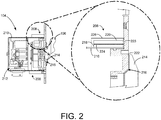
- FIG. 2 is a cross-sectional view of the AoA sensor 104 using a heating apparatus 208 to maintain the temperature of a portion of the AoA sensor 104 according to at least one embodiment disclosed herein.
- the AoA sensor 104 includes outer casing 210.
- the outer casing 210 is configured to enclose an inner volume 212 of the AoA sensor 104.
- the inner volume 212 is defined by the inner surface of the outer casing 210.
- the inner volume 212 is used to enclose and protect various electrical and mechanical componentry of the AoA sensor 104 from the environment. But, some portions of the AoA sensor 104 are exposed to the environment.
- the airfoil-shaped body 106 is exposed to the outside airflow.
- the airfoil-shaped body 106 is affixed to a rotatable mount 214.
- the rotatable mount 214 does not sit flush, or abut, the AoA sensor 104, leaving a space 216 between the rotatable mount 214 and the AoA sensor 104.
- An example of the space 216 is illustrated using a cross hatch pattern. In some configurations, water can enter the space 216 and freeze, impeding the rotation of the rotatable mount 214.
- the heating apparatus 208 may be used.
- the heating apparatus 208 includes a support element 218 and a heating element 220.
- the heating element 220 may be a resistive element that, when a certain amount of current is applied, generates heat.
- the heating apparatus 208 surrounds at least a portion of the outer casing 210.
- the heating apparatus 208 preferably is in direct contact with the outer casing 210. Heat generated by the heating apparatus 208 is configured to raise the temperature of the outer casing 210 and the faceplate 222.
- the heat from the outer casing 210 preferably raises the temperature of the face plate 222 of the AoA sensor 104.
- the increase in temperature of the faceplate 222 preferably reduces the probability that ice will form in the space 216 between the faceplate 222 and the rotatable mount 214.
- the reduction of the probability of the buildup of ice can increase the reliability and accuracy of the AoA sensor 104.
- increased heat transfer may be provided by abutting the heating apparatus 208 to an inner surface 223 of the faceplate 222.
- the support element 218 of the heating apparatus 208 may be used to provide structural support to the heating apparatus 208.
- the heating apparatus 208 is securely affixed to the outer casing 210.
- the heating apparatus 208 may have a level of rigidity able to withstand the forces of securement. Further, it may be necessary that the heating apparatus 208 has a level of rigidity able to withstand forces, especially vibrational forces, experienced during the operation of the aircraft 100.
- the support element 218 may be, in a configuration, a metal collar.
- the support element 218 may provide a substrate upon which the heating element 220 is affixed.
- the heating element 220 is manufactured from one or more polymeric components.
- the heating element 220 may be formed from one or more "polymer blacks," e.g. polyacetylene, polypyrrole, polyaniline, p-phenylene vinylene, and their copolymers.
- the heating element 220 is a polymeric material with a suitable amount of conductive substance, such as carbon black, added to the polymeric material to achieve a desired level of conductivity.
- the heating element 220 may be a metallic-based heating element that uses a metallic conducting element, such as copper, silver, gold, or aluminum, to act as the conductor in the heating element 220.
- the heating element 220 is affixed or bonded directly to the support element 218 using a bonding agent 224 to form a composite structure configured to act as an electrical heating element.
- the bonding agent 224 may be any suitable material for bonding the heating element 220 to the support element 218.
- the bonding agent 224 may be a polyimide adhesive.
- the bonding agent 224 may be activated and cause the heating element 220 to be bonded to the support element 218 using various processes, including the use of an autoclave.
- a polyimide adhesive may be beneficial because of the general characteristics of polyimide adhesives. Some characteristics include a relatively good thermal stability, a low dielectric constant, and a relatively high level of chemical resistivity.
- the heating apparatus 208 may also include insulation 226.
- the insulation 226 may be configured to reduce the amount of heat lost from the heating apparatus 208 into the environment, and increase the amount of heat transferred to various locations of the AoA sensor 104, such as the face plate 222.
- the insulation 226 may be formed from appropriate, thermally insulative materials.
- the insulation 226 may be formed from a heat reflective metal, ceramic, glass fiber sheet/matting, silica, mica, glass wool, asbestos, silk wool, and thermally insulative polymers.
- FIG. 3 is an exploded perspective view of the AoA sensor 104 according to at least one embodiment disclosed herein.
- the AoA sensor 104 includes the airfoil-shaped body 106 affixed to the rotatable mount 214.
- the rotatable mount 214 is rotatably affixed to the faceplate 222.
- the faceplate 222 is removably cooperatively affixed to a sensor receiving area 302 of the aircraft 100.
- the faceplate 222 is sized to fit within the sensor receiving area 302 to provide a flush mount for the AoA sensor 104.
- the faceplate 222 may be affixed to the sensor receiving area 302 using screws, such as the screw 304.
- FIG. 4 is a perspective view of the heating apparatus 208 according to at least one embodiment disclosed herein.
- the heating apparatus 208 includes a support element 218 and a heating element 220.
- the heating element 220 is disposed around at least a portion of the support element 218.
- the support element 218, along with the heating element 220, may be removably installed on the AoA sensor 104.
- the heating element 220 may be a resistive, or Joule, heating element.
- a resistive heating element creates heat when current is passed through the resistive heating element.
- the resistance of the resistive heating element causes heat to be generated.
- the heating element 220 may also be constructed from materials such as nichrome, resistive wire or braid, etched foil, ceramics such as molybdenum disilicide, and composite heating elements. It should be understood, though, that other materials may be used and are considered to be within the scope of the present disclosure. Further, it should be understood that the present disclosure is not limited to resistive heating elements, as other types of heating elements may be used and are considered to be within the scope of the present disclosure.
- the heating element 220 may receive electrical power through electrical wires 400 and 402.
- the wires 400 and 402 may provide an electrical path from an electrical source to provide current to the heating element 220.
- the electrical current may be controlled in various ways to increase or decrease the temperature of the heating element 220.
- a control thermostat 404 may be used.
- the control thermostat 404 may be configured to detect the temperature of the heating element 220.
- the control thermostat 404 may close a previously open switch (not shown) internal to the control thermostat 404. Closing the switch may cause the formation of a closed loop, allowing current to flow through the wires 400 and 402.
- the control thermostat 404 opens the switch, preventing or reducing the flow of current through the wires 400 and 402.
- the temperature of the heating element 220 may be controlled by the control thermostat 404.
- the first temperature may be a temperature to reduce ice formation.
- the second temperature may be a temperature to prevent damage to the AoA sensor 104.
- control thermostat 404 may operate as a type of proportional-integral-derivative (PID) controller.
- PID controller calculates an "error" value as the difference between a measured process variable and a desired set point. The controller attempts to minimize the error in outputs by adjusting the process control inputs.
- the control thermostat 404 is a PID controller, instead of an "off or on” functionality, the control thermostat may incrementally increase or incrementally decrease the current flow to the heating element 220 to maintain a temperature.
- the control thermostat 404 may receive the temperature input from temperature detectors 408A-408N (hereinafter collectively referred to as the "temperature detectors 408").
- the temperature detectors 408 may be one or more devices that sense a temperature at a location in the AoA sensor 104 or the heating apparatus 208, or both.
- the temperature detectors 408 are further configured to provide a temperature output to the control thermostat 404.
- the control thermostat 404 is configured to receive the temperature output.
- the temperature detectors 408 may be located in various locations to provide a range of temperature inputs to the control thermostat 404.
- the control thermostat 404 may have internal temperature detectors 408. In other configurations, the temperature detectors 408 may be external to the control thermostat 404 and placed in various locations.
- the heating apparatus 208 may receive power through electrical leads 410.
- the electrical leads 410 may introduce various types of power into the heating apparatus 208.
- the heating apparatus 208 is provided power in an independent manner from the AoA sensor 104.
- the heating apparatus 208 may be part of an aircraft's Air Data Heat System.
- the Air Data Heat System may also control and power the AoA sensor 104 in an independent manner from the heating apparatus 208.
- Power may be provided to the heating apparatus 208 either manually or automatically.
- the heating apparatus 208 may be activated by the flight crew per a checklist, or automatically (independent of manual activation or deactivation) by other airplane means, such as when the flight crew activates the engine's fuel switches.
- the heating apparatus 208 may be secured around the AoA sensor 104 using a hinge 406, illustrated in further detail in FIG. 5 .
- An additional configuration of the heating apparatus 208 is shown in a cross-sectional view in FIG. 7 taken across plane T of FIG. 4 .
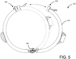
- FIG. 5 is a bottom view of the heating apparatus 208 in an open configuration according to at least one embodiment disclosed herein.
- the support element 218 of the heating apparatus 208 has been opened using the hinge 406.
- the hinge 406 provides a point of rotation to which a first end 502 of the support element 218 and a second end 504 of the support element.
- the space provided by the separation may be used to place the heating apparatus 208 onto the outer casing 210 of the AoA sensor 104.
- the first end 502 may be releasably affixed to the second end 504 through the use of a fastener, illustrated in further detail in FIG. 6 .
- FIG. 6 is a top view of the heating apparatus 208 in a closed configuration according to at least one embodiment disclosed herein.
- the first end 502 is releasably affixed to the second end 504 using a fastener 600.
- the fastener 600 may be constructed in any manner suitable to secure the first end 502 to the second end 504. It should be understood that other configurations of the presently disclosed subject matter may forego the use of the fastener 600.
- the hinge 406 may be a spring-loaded hinge designed to exert a closing force on the support element 218 of the heating apparatus 208.
- the heating apparatus 208 may be desirable or necessary to provide a means to indicate that the heating apparatus 208 has been secured affixed to the outer casing 210 of the AoA sensor 104.
- a technician may use the fastener 600.
- the heating apparatus 208 when installed, has void 602 defined by the area between the first end 502 and the second end 504. The void 602 may be used as an indicator that the heating apparatus 208 is fully installed on the AoA sensor 104.
- the absence of the void 602 may indicate that the inner diameter of the heating apparatus 208 is too large for the AoA sensor 104 and, thus, may extricate from the AoA sensor 104.
- the absence of the void 602 may also indicate an over-tightening of the heating apparatus 208, possibly indicating damage to the outer casing 210.
- FIG. 6 also illustrates a fuse 604.
- the fuse 604 may fault or open in various situations.
- the fuse 604 may open in an overcurrent or over-temperature condition.
- the fuse 604 may open in the event the control thermostat 404 fails closed. If the control thermostat 404 fails closed, there may be no means of heater shutoff. In this example, therefore, the fuse 604 may provide a means to prevent the over-temperature condition.
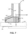
- FIG. 7 is a cross-sectional view of a portion of the heating apparatus 208 taken across the plane T illustrated in FIG. 4 according to at least one embodiment disclosed herein.
- the heating apparatus 208 includes the support element 218, the heating element 220 disposed proximate to an outer surface of the heating apparatus 208, and the insulation 226 installed around at least a portion of the heating apparatus.
- a bonding agent may be used to affix the heating element 220 to the support element 218, such as the bonding agent 224.
- At least a portion of the support element 218 abuts a portion of the outer casing 210.
- the surface of the support element 218 in contact with the outer casing may have a smooth or semi-smooth finish to provide a better heat transfer interface.
- the heat generated by the heating element 220 may be transferred to the support element 218 and may flow in two general directions: radially in the direction of X ⁇ A and laterally in the direction of X ⁇ 7 B. If the total heat generated by the heating element 220 flows primarily in the direction X ⁇ A, the temperature of the inner volume 212 of the AoA sensor 104 may be affected, while the temperature of the space 216 (a location for possible ice formation) may be effected in an amount unsuitable to reduce the probability of ice formation. In a different manner, if the total heat generated by the heating element 220 flows primarily in the direction X ⁇ B, the temperature of the space 216 may be affected in a suitable amount, thus reducing the probability of ice formation.
- the support element 218 may include a flange 700 having a radial portion 702 and a lateral portion 704.
- the flange 700 may abut the inner surface 223 of the face plate 222, as illustrated in FIG. 2 , above.
- the lateral portion 704 in combination with the radial portion 702 of the flange 700 may present a larger heat transfer surface area for the transfer of heat to space 216 than would otherwise be present without lateral portion 704 of the flange 700.
- the larger heat transfer surface area may increase the heat flow generated by the heating element 220 in the lateral direction X ⁇ B towards the inner surface of the face plate 222.
- the increased heat flow may "focus" the heat generated by the heating element 220 towards an area of concern, such as the space 216, rather than other areas of less concern, such as the inner volume 212 of the AoA sensor 104.
- a portion of the heating element 220 may be disposed on the flange 700.
- FIG. 8 illustrates one configuration of a routine 800 for operating an AoA sensor heating apparatus according to at least one embodiment disclosed herein. Unless otherwise indicated, more or fewer operations may be performed than shown in the figures and described herein. Additionally, unless otherwise indicated, these operations may also be performed in a different order than those described herein.
- the routine 800 commences at operation 802, where an input of a temperature of a surface of an AoA sensor is received.
- the temperature may be received directly by the control thermostat 404 via direct thermal contact.
- the temperature may be received by external temperature detectors 408.
- the surface may be one of several surfaces monitored in the AoA sensor 104.
- the one or more surfaces are selected based on the probability that conditions conducive to ice formation can be detected at the one or more surfaces.
- the temperature may be a space surrounding one or more components of the AoA sensor 104.
- the temperatures may be detected using the temperature detectors 408.
- the detected temperature may be outputted to the control thermostat 404, which may receive the temperature output as an input.
- the routine 800 continues to operation 804, where in response to detecting that the temperature is at or below a first temperature set point, allowing current to flow through a resistive element of a heating apparatus, the resistive element bonded to a support element.
- the resistive element may be the heating element 220 of the AoA sensor 104.
- the support element may be the support element 218 of the AoA sensor 104.
- the first temperature may be a temperature to reduce ice formation.
- the routine 800 continues to operation 806, where in response to detecting that the temperature is at or above a second temperature set point, reducing current flow through the resistive element of the AoA sensor 104.
- the second temperature may be a temperature to prevent damage to the AoA sensor 104.
- the routine thereafter ends.
Landscapes
- Engineering & Computer Science (AREA)
- Aviation & Aerospace Engineering (AREA)
- Physics & Mathematics (AREA)
- General Physics & Mathematics (AREA)
- Control Of Resistance Heating (AREA)
- Resistance Heating (AREA)
Claims (13)
- AoA-Sensorsystem für ein Luftfahrzeug, das aufweist:einen AoA-Sensor (104), der aufweisteinen tragflächenförmigen Körper (106), der an einer drehbaren Halterung (214) befestigt ist;wobei die drehbare Halterung (214) drehbar an dem AoA-Sensor (104) befestigt ist; undeine Heizvorrichtung (208), die entfernbar an dem AoA-Sensor (104) befestigt ist und die zum Verringern einer Eisbildung auf dem AoA-Sensor (104) eingerichtet ist, wobei die Heizvorrichtung aufweistein Halteelement (218), das zum lösbaren In-Eingriff-Bringen mit dem AoA-Sensor (104) eingerichtet ist,ein Heizelement (220), das an das Halteelement (218) gebunden ist, um eine Verbundstruktur zu bilden, undeinen Steuerthermostat (404), der zum Empfangen einer Tempera-tureingabe und zum Ermöglichen eines Stromflusses durch das Heizelement (220) bei oder unterhalb einer ersten Temperatur und zum Verringern eines Stromflusses durch das Heizelement (220) bei oder oberhalb einer zweiten Temperatur eingerichtet ist.
- AoA-Sensorsystem nach Anspruch 1, wobei das Halteelement (218) einen Metallkragen aufweist.
- AoA-Sensorsystem nach einem der Ansprüche 1 bis 2, wobei das Halteelement (218) ein Gelenk (406) aufweist, um ein erstes Ende (502) des Halteelements drehbar zu einem zweiten Ende (504) des Halteelements zu machen.
- AoA-Sensorsystem nach Anspruch 3, das des Weiteren eine Befestigungseinrichtung (600) zum lösbaren Befestigen des ersten Endes (502) des Halteelements (218) an dem zweiten Ende (504) des Halteelements aufweist.
- AoA-Sensorsystem nach einem der Ansprüche 1 bis 4, das des Weiteren eine Polyimidverbindung (224) zwischen dem Halteelement (218) und dem Heizelement (220) aufweist, um das Halteelement direkt mit dem Heizelement zu verbinden.
- AoA-Sensorsystem nach einem der Ansprüche 1 bis 5, wobei das Heizelement (220) aus einem Material gebildet ist, welches aus der Gruppe ausgewählt ist, die aus Polyacetylen, Polypyrrol, Polyanilin und p-Phenylendiamin-Vinylen und Copolymeren aus Polyacetylen, Polypyrrol, Polyanilin und p-Phenylen-Vinylen besteht.
- AoA-Sensorsystem nach einem der Ansprüche 1 bis 6, wobei der Steuerthermostat (404) in Wärmeverbindung mit der Heizvorrichtung (208) steht.
- AoA-Sensorsystem nach einem der Ansprüche 1 bis 7, das des Weiteren eine Isolierung (226) aufweist, um eine Wärmemenge zu verringern, die durch die Heizvorrichtung (208) an die Umwelt verloren wird, wobei die Isolierung aus einem Material gebildet ist, das aus der Gruppe gewählt ist, die aus einem wärmereflektierenden Metall, Keramik, Glasfaser-Schicht/Matte, Silizium, Glimmer, Glaswolle, Asbest, Seidenwolle und thermisch isolierenden Polymeren besteht.
- AoA-Sensorsystem nach einem der Ansprüche 1 bis 8, wobei die erste Temperatur eine Temperatur zum Verringern einer Eisbildung ist und wobei die zweite Temperatur eine Temperatur zum Verhindern einer Beschädigung des AoA-Sensors (104) ist.
- Verfahren zum Schützen des Betriebs eines AoA-Sensors (104) unter Vereisungsbedingungen, wobei ein tragflächenförmiger Körper (106), der an einer drehbaren Halterung (214) befestigt ist, auf einer Außenfläche einer Frontplatte (222) angeordnet ist, wobei der AoA-Sensor (104) innerhalb eines Gehäuses (210) vorgesehen ist, welches an einer Innenfläche der Frontplatte (222) befestigt ist, und wobei ein Spalt (216) zwischen der drehbaren Halterung (214) und der Frontplatte (222) definiert ist, wobei der Spalt empfindlich gegenüber einem Eindringen von Wasser und einem nachfolgenden Frieren hinsichtlich einer gehinderten Drehung der drehbaren Halterung (214) relativ zur Frontplatte (222) ist, aufweisend:Anbringen einer Heizvorrichtung (208) an dem Äußeren des Gehäuses (210), wobei die Heizvorrichtung ein Halteelement (218), ein Heizelement (220), das an das Halteelement (218) gebunden ist, um eine Verbundstruktur zu bilden, und ein Steuerthermostat (404) aufweist; undSteuern der Heizvorrichtung (208), so dass sie eine Temperatur beibehält, die zum Verhindern eines Frierens des Wassers in dem Spalt (216) ausreichend ist, jedoch nicht ausreicht, um den AoA-Sensor (104) zu beschädigen, indemeine Temperatureingabe empfangen wird und ein Stromfluss mittels des Steuerthermostats (404) durch das Heizelement (202) bei oder unterhalb einer ersten Temperatur zugelassen wird undindem ein Stromfluss mittels des Steuerthermostats (404) durch das Heizelement (220) bei oder über einer zweiten Temperatur verringert wird.
- Verfahren nach Anspruch 10, wobei die Heizvorrichtung (208) derart geformt ist, dass sie das Gehäuse (210) umgibt.
- Verfahren nach einem der Ansprüche 10-11, wobei die Heizvorrichtung (208) ein Gelenk (416) umfasst, so dass sie lösbar an dem Gehäuse (210) angebracht ist.
- Verfahren nach einem der Ansprüche 10-12, wobei die Heizvorrichtung (208) sich in einem direkten Kontakt mit der Innenfläche der Frontplatte (222) befindet.
Applications Claiming Priority (1)
| Application Number | Priority Date | Filing Date | Title |
|---|---|---|---|
| US14/288,891 US9884685B2 (en) | 2014-05-28 | 2014-05-28 | External case heater for an angle of attack sensor |
Publications (2)
| Publication Number | Publication Date |
|---|---|
| EP2950106A1 EP2950106A1 (de) | 2015-12-02 |
| EP2950106B1 true EP2950106B1 (de) | 2016-12-28 |
Family
ID=53016527
Family Applications (1)
| Application Number | Title | Priority Date | Filing Date |
|---|---|---|---|
| EP15165557.8A Active EP2950106B1 (de) | 2014-05-28 | 2015-04-29 | Externe heizung für ein angriffswinkel-sensorgehäuse |
Country Status (6)
| Country | Link |
|---|---|
| US (1) | US9884685B2 (de) |
| EP (1) | EP2950106B1 (de) |
| JP (1) | JP6556471B2 (de) |
| CN (1) | CN105142246B (de) |
| BR (1) | BR102015009906B1 (de) |
| RU (1) | RU2673331C2 (de) |
Families Citing this family (24)
| Publication number | Priority date | Publication date | Assignee | Title |
|---|---|---|---|---|
| CN105966635A (zh) * | 2016-05-25 | 2016-09-28 | 江西洪都航空工业集团有限责任公司 | 一种可兼容多型传感器安装的防水支架 |
| US10100240B2 (en) * | 2016-08-30 | 2018-10-16 | The Boeing Company | Electrostatic dissipative compositions and methods thereof |
| US10457412B2 (en) * | 2016-09-16 | 2019-10-29 | Rosemount Aerospace Inc. | Electrical isolation of angle of attack vane bearings |
| US10197588B2 (en) | 2016-11-09 | 2019-02-05 | Honeywell International Inc. | Thin film heating systems for air data probes |
| US10730637B2 (en) * | 2017-09-29 | 2020-08-04 | Rosemount Aerospace Inc. | Integral vane base angle of attack sensor |
| US10393766B2 (en) | 2017-08-17 | 2019-08-27 | Rosemount Aerospace Inc. | Water management system for angle of attack sensors |
| US11181545B2 (en) * | 2017-08-17 | 2021-11-23 | Rosemount Aerospace Inc. | Angle of attack sensor with thermal enhancement |
| EP4001119B1 (de) | 2018-01-05 | 2024-06-05 | Rosemount Aerospace Inc. | Merkmale zur vermeidung von eisansammlungen auf beheizten frontplatten |
| US10716171B2 (en) | 2018-03-23 | 2020-07-14 | Rosemount Aerospace Inc. | Power efficient heater control of air data sensor |
| US10877062B2 (en) * | 2018-05-09 | 2020-12-29 | Rosemount Aerospace Inc. | Aft-located heated ramp for ice and water management of angle of attack sensors |
| US10928416B2 (en) | 2018-05-09 | 2021-02-23 | Rosemount Aerospace Inc. | Dual heated ramp for ice and water management in angle of attack sensors |
| US11162970B2 (en) | 2019-06-17 | 2021-11-02 | Rosemount Aerospace Inc. | Angle of attack sensor |
| KR102051098B1 (ko) * | 2019-07-05 | 2019-12-02 | 국방과학연구소 | Fads의 방빙을 위한 능동히터 장치 |
| US11585826B2 (en) | 2019-07-19 | 2023-02-21 | Rosemount Aerospace Inc. | Thin film heater on a sleeve outer surface in a strut portion and/or a probe head of an air data probe |
| US11814181B2 (en) * | 2019-12-11 | 2023-11-14 | Rosemount Aerospace Inc. | Conformal thin film heaters for angle of attack sensors |
| US11649057B2 (en) * | 2019-12-13 | 2023-05-16 | Rosemount Aerospace Inc. | Static plate heating arrangement |
| US12360134B2 (en) | 2020-02-25 | 2025-07-15 | Rosemount Aerospace Inc. | Angle of attack sensor with sloped faceplate |
| US11745879B2 (en) | 2020-03-20 | 2023-09-05 | Rosemount Aerospace Inc. | Thin film heater configuration for air data probe |
| US11150262B1 (en) * | 2020-04-24 | 2021-10-19 | Christohper Williams | System and method for angle of attack sensor |
| US12037131B2 (en) | 2021-01-12 | 2024-07-16 | The Boeing Company | Charged air mass measurement for air data computation |
| FR3123448B1 (fr) | 2021-05-27 | 2023-07-14 | Thales Sa | Sonde de mesure aérodynamique |
| FR3125129B1 (fr) * | 2021-07-07 | 2023-07-14 | Thales Sa | Sonde d'incidence notamment pour un aéronef |
| US11912420B2 (en) * | 2022-04-11 | 2024-02-27 | The Boeing Company | Deicing systems and methods for an aircraft |
| US20260036604A1 (en) * | 2024-08-01 | 2026-02-05 | The Boeing Company | Systems and methods for estimating a speed of a vehicle |
Family Cites Families (20)
| Publication number | Priority date | Publication date | Assignee | Title |
|---|---|---|---|---|
| US2918817A (en) * | 1955-10-03 | 1959-12-29 | G M Giannini & Co Inc | Fluid stream direction indicator with mechanical filter |
| US4292503A (en) * | 1979-05-14 | 1981-09-29 | Emerson Electric Co. | Split-band electric heater |
| US4875644A (en) * | 1988-10-14 | 1989-10-24 | The B. F. Goodrich Company | Electro-repulsive separation system for deicing |
| US4912303A (en) * | 1989-02-17 | 1990-03-27 | Beavers Allan E | Electric heating belt for liquid propane bottles |
| US5062869A (en) * | 1989-03-08 | 1991-11-05 | Rosemount Inc. | Water separator for air data sensor |
| FR2646966B1 (fr) * | 1989-05-10 | 1996-02-02 | Elf Aquitaine | Procede de chauffage rapide et uniforme d'un ensemble multicouche comportant au moins une couche mince a base d'un materiau macromoleculaire a conduction ionique intercalee entre deux structures a conduction electronique elevee |
| US5025661A (en) * | 1989-12-11 | 1991-06-25 | Allied-Signal Inc. | Combination air data probe |
| US5438865A (en) | 1993-12-16 | 1995-08-08 | Safe Flight Instrument Corporation | Angle of attack sensor |
| US5586896A (en) * | 1995-01-11 | 1996-12-24 | The Whitaker Corporation | Heater ring connector assembly |
| US5959828A (en) * | 1996-07-16 | 1999-09-28 | Hydraflow | Coupling with insulated flanges |
| RU2098323C1 (ru) * | 1996-10-17 | 1997-12-10 | Йелстаун Корпорейшн Н.В. | Система электропитания противообледенительных элементов винта самолета |
| US6211494B1 (en) * | 1999-08-25 | 2001-04-03 | The B. F. Goodrich Company | Drainmast with integral electronic temperature control |
| JP2001221809A (ja) * | 2000-02-10 | 2001-08-17 | Windo Service:Kk | 機器の雪害防止装置 |
| US6414282B1 (en) * | 2000-11-01 | 2002-07-02 | Rosemount Aerospace Inc. | Active heater control circuit and method used for aerospace probes |
| FR2830620B1 (fr) * | 2001-10-05 | 2004-01-16 | Thales Sa | Dispositif de securisation du deplacement d'un organe mobile |
| US6612166B2 (en) | 2001-12-13 | 2003-09-02 | Rosemount Aerospace Inc. | Variable viscosity damper for vane type angle of attack sensor |
| US6941805B2 (en) * | 2003-06-26 | 2005-09-13 | Rosemount Aerospace Inc. | Multi-function air data sensing probe having an angle of attack vane |
| FR2891241B1 (fr) * | 2005-09-23 | 2009-03-13 | Airbus France Sas | Systeme de degivrage et/ou de desembuage d'une surface d'un aeronef, procede de commande d'un tel systeme, et aeronef equipe d'un tel systeme. |
| FR2924498B1 (fr) * | 2007-11-30 | 2009-12-11 | Thales Sa | Girouette de mesure de l'orientation du vent a rechauffeur integre |
| US20140014776A1 (en) * | 2012-07-13 | 2014-01-16 | Kelly Aerospace Thermal Systems Llc | System containing an electric heating element and method for installation and use thereof |
-
2014
- 2014-05-28 US US14/288,891 patent/US9884685B2/en active Active
-
2015
- 2015-03-04 RU RU2015107535A patent/RU2673331C2/ru active
- 2015-03-10 JP JP2015046889A patent/JP6556471B2/ja active Active
- 2015-04-29 EP EP15165557.8A patent/EP2950106B1/de active Active
- 2015-04-30 BR BR102015009906-1A patent/BR102015009906B1/pt active IP Right Grant
- 2015-05-27 CN CN201510280523.0A patent/CN105142246B/zh active Active
Non-Patent Citations (1)
| Title |
|---|
| None * |
Also Published As
| Publication number | Publication date |
|---|---|
| CN105142246B (zh) | 2020-03-10 |
| BR102015009906B1 (pt) | 2022-06-28 |
| JP6556471B2 (ja) | 2019-08-07 |
| JP2015224021A (ja) | 2015-12-14 |
| CN105142246A (zh) | 2015-12-09 |
| US9884685B2 (en) | 2018-02-06 |
| RU2015107535A (ru) | 2016-09-27 |
| RU2015107535A3 (de) | 2018-09-13 |
| US20150344137A1 (en) | 2015-12-03 |
| RU2673331C2 (ru) | 2018-11-23 |
| BR102015009906A2 (pt) | 2015-12-29 |
| EP2950106A1 (de) | 2015-12-02 |
Similar Documents
| Publication | Publication Date | Title |
|---|---|---|
| EP2950106B1 (de) | Externe heizung für ein angriffswinkel-sensorgehäuse | |
| EP2092286B1 (de) | Integrierte gesamtlufttemperatursonde und elektronik | |
| EP2428447B1 (de) | Eiserkennungssystem und -verfahren | |
| RU2534493C2 (ru) | Система и способ применения датчика обледенения | |
| US9097734B2 (en) | Ceramic heating device | |
| CN115723961A (zh) | 具有故障预测和健康管理的一体式防冰装置 | |
| EP3836747A1 (de) | Konforme dünnschichtheizelemente für anstellwinkelsensoren | |
| CA2894045C (en) | Thermal sensor | |
| EP3478025B1 (de) | Selbstregelnde heizerkompensation | |
| KR102051098B1 (ko) | Fads의 방빙을 위한 능동히터 장치 | |
| EP3639622B1 (de) | Flexibler widerstand | |
| CN121425500A (zh) | 机翼除冰装置和航空器 | |
| TR202005746Y (tr) | Bir buzlanma koruma sistemi, |
Legal Events
| Date | Code | Title | Description |
|---|---|---|---|
| AK | Designated contracting states |
Kind code of ref document: A1 Designated state(s): AL AT BE BG CH CY CZ DE DK EE ES FI FR GB GR HR HU IE IS IT LI LT LU LV MC MK MT NL NO PL PT RO RS SE SI SK SM TR |
|
| AX | Request for extension of the european patent |
Extension state: BA ME |
|
| PUAI | Public reference made under article 153(3) epc to a published international application that has entered the european phase |
Free format text: ORIGINAL CODE: 0009012 |
|
| GRAP | Despatch of communication of intention to grant a patent |
Free format text: ORIGINAL CODE: EPIDOSNIGR1 |
|
| 17P | Request for examination filed |
Effective date: 20160524 |
|
| RBV | Designated contracting states (corrected) |
Designated state(s): AL AT BE BG CH CY CZ DE DK EE ES FI FR GB GR HR HU IE IS IT LI LT LU LV MC MK MT NL NO PL PT RO RS SE SI SK SM TR |
|
| INTG | Intention to grant announced |
Effective date: 20160705 |
|
| GRAS | Grant fee paid |
Free format text: ORIGINAL CODE: EPIDOSNIGR3 |
|
| GRAA | (expected) grant |
Free format text: ORIGINAL CODE: 0009210 |
|
| AK | Designated contracting states |
Kind code of ref document: B1 Designated state(s): AL AT BE BG CH CY CZ DE DK EE ES FI FR GB GR HR HU IE IS IT LI LT LU LV MC MK MT NL NO PL PT RO RS SE SI SK SM TR |
|
| REG | Reference to a national code |
Ref country code: GB Ref legal event code: FG4D |
|
| REG | Reference to a national code |
Ref country code: CH Ref legal event code: EP |
|
| REG | Reference to a national code |
Ref country code: AT Ref legal event code: REF Ref document number: 857759 Country of ref document: AT Kind code of ref document: T Effective date: 20170115 |
|
| REG | Reference to a national code |
Ref country code: IE Ref legal event code: FG4D |
|
| REG | Reference to a national code |
Ref country code: DE Ref legal event code: R096 Ref document number: 602015001107 Country of ref document: DE |
|
| PG25 | Lapsed in a contracting state [announced via postgrant information from national office to epo] |
Ref country code: LV Free format text: LAPSE BECAUSE OF FAILURE TO SUBMIT A TRANSLATION OF THE DESCRIPTION OR TO PAY THE FEE WITHIN THE PRESCRIBED TIME-LIMIT Effective date: 20161228 |
|
| REG | Reference to a national code |
Ref country code: LT Ref legal event code: MG4D |
|
| REG | Reference to a national code |
Ref country code: FR Ref legal event code: PLFP Year of fee payment: 3 |
|
| PG25 | Lapsed in a contracting state [announced via postgrant information from national office to epo] |
Ref country code: GR Free format text: LAPSE BECAUSE OF FAILURE TO SUBMIT A TRANSLATION OF THE DESCRIPTION OR TO PAY THE FEE WITHIN THE PRESCRIBED TIME-LIMIT Effective date: 20170329 Ref country code: SE Free format text: LAPSE BECAUSE OF FAILURE TO SUBMIT A TRANSLATION OF THE DESCRIPTION OR TO PAY THE FEE WITHIN THE PRESCRIBED TIME-LIMIT Effective date: 20161228 Ref country code: LT Free format text: LAPSE BECAUSE OF FAILURE TO SUBMIT A TRANSLATION OF THE DESCRIPTION OR TO PAY THE FEE WITHIN THE PRESCRIBED TIME-LIMIT Effective date: 20161228 Ref country code: NO Free format text: LAPSE BECAUSE OF FAILURE TO SUBMIT A TRANSLATION OF THE DESCRIPTION OR TO PAY THE FEE WITHIN THE PRESCRIBED TIME-LIMIT Effective date: 20170328 |
|
| REG | Reference to a national code |
Ref country code: NL Ref legal event code: MP Effective date: 20161228 |
|
| REG | Reference to a national code |
Ref country code: AT Ref legal event code: MK05 Ref document number: 857759 Country of ref document: AT Kind code of ref document: T Effective date: 20161228 |
|
| PG25 | Lapsed in a contracting state [announced via postgrant information from national office to epo] |
Ref country code: RS Free format text: LAPSE BECAUSE OF FAILURE TO SUBMIT A TRANSLATION OF THE DESCRIPTION OR TO PAY THE FEE WITHIN THE PRESCRIBED TIME-LIMIT Effective date: 20161228 Ref country code: HR Free format text: LAPSE BECAUSE OF FAILURE TO SUBMIT A TRANSLATION OF THE DESCRIPTION OR TO PAY THE FEE WITHIN THE PRESCRIBED TIME-LIMIT Effective date: 20161228 Ref country code: FI Free format text: LAPSE BECAUSE OF FAILURE TO SUBMIT A TRANSLATION OF THE DESCRIPTION OR TO PAY THE FEE WITHIN THE PRESCRIBED TIME-LIMIT Effective date: 20161228 |
|
| PG25 | Lapsed in a contracting state [announced via postgrant information from national office to epo] |
Ref country code: NL Free format text: LAPSE BECAUSE OF FAILURE TO SUBMIT A TRANSLATION OF THE DESCRIPTION OR TO PAY THE FEE WITHIN THE PRESCRIBED TIME-LIMIT Effective date: 20161228 |
|
| PG25 | Lapsed in a contracting state [announced via postgrant information from national office to epo] |
Ref country code: CZ Free format text: LAPSE BECAUSE OF FAILURE TO SUBMIT A TRANSLATION OF THE DESCRIPTION OR TO PAY THE FEE WITHIN THE PRESCRIBED TIME-LIMIT Effective date: 20161228 Ref country code: IS Free format text: LAPSE BECAUSE OF FAILURE TO SUBMIT A TRANSLATION OF THE DESCRIPTION OR TO PAY THE FEE WITHIN THE PRESCRIBED TIME-LIMIT Effective date: 20170428 Ref country code: EE Free format text: LAPSE BECAUSE OF FAILURE TO SUBMIT A TRANSLATION OF THE DESCRIPTION OR TO PAY THE FEE WITHIN THE PRESCRIBED TIME-LIMIT Effective date: 20161228 Ref country code: SK Free format text: LAPSE BECAUSE OF FAILURE TO SUBMIT A TRANSLATION OF THE DESCRIPTION OR TO PAY THE FEE WITHIN THE PRESCRIBED TIME-LIMIT Effective date: 20161228 Ref country code: RO Free format text: LAPSE BECAUSE OF FAILURE TO SUBMIT A TRANSLATION OF THE DESCRIPTION OR TO PAY THE FEE WITHIN THE PRESCRIBED TIME-LIMIT Effective date: 20161228 |
|
| PG25 | Lapsed in a contracting state [announced via postgrant information from national office to epo] |
Ref country code: BG Free format text: LAPSE BECAUSE OF FAILURE TO SUBMIT A TRANSLATION OF THE DESCRIPTION OR TO PAY THE FEE WITHIN THE PRESCRIBED TIME-LIMIT Effective date: 20170328 Ref country code: IT Free format text: LAPSE BECAUSE OF FAILURE TO SUBMIT A TRANSLATION OF THE DESCRIPTION OR TO PAY THE FEE WITHIN THE PRESCRIBED TIME-LIMIT Effective date: 20161228 Ref country code: PT Free format text: LAPSE BECAUSE OF FAILURE TO SUBMIT A TRANSLATION OF THE DESCRIPTION OR TO PAY THE FEE WITHIN THE PRESCRIBED TIME-LIMIT Effective date: 20170428 Ref country code: BE Free format text: LAPSE BECAUSE OF FAILURE TO SUBMIT A TRANSLATION OF THE DESCRIPTION OR TO PAY THE FEE WITHIN THE PRESCRIBED TIME-LIMIT Effective date: 20161228 Ref country code: AT Free format text: LAPSE BECAUSE OF FAILURE TO SUBMIT A TRANSLATION OF THE DESCRIPTION OR TO PAY THE FEE WITHIN THE PRESCRIBED TIME-LIMIT Effective date: 20161228 Ref country code: PL Free format text: LAPSE BECAUSE OF FAILURE TO SUBMIT A TRANSLATION OF THE DESCRIPTION OR TO PAY THE FEE WITHIN THE PRESCRIBED TIME-LIMIT Effective date: 20161228 Ref country code: SM Free format text: LAPSE BECAUSE OF FAILURE TO SUBMIT A TRANSLATION OF THE DESCRIPTION OR TO PAY THE FEE WITHIN THE PRESCRIBED TIME-LIMIT Effective date: 20161228 Ref country code: ES Free format text: LAPSE BECAUSE OF FAILURE TO SUBMIT A TRANSLATION OF THE DESCRIPTION OR TO PAY THE FEE WITHIN THE PRESCRIBED TIME-LIMIT Effective date: 20161228 |
|
| REG | Reference to a national code |
Ref country code: DE Ref legal event code: R097 Ref document number: 602015001107 Country of ref document: DE |
|
| PLBE | No opposition filed within time limit |
Free format text: ORIGINAL CODE: 0009261 |
|
| STAA | Information on the status of an ep patent application or granted ep patent |
Free format text: STATUS: NO OPPOSITION FILED WITHIN TIME LIMIT |
|
| PG25 | Lapsed in a contracting state [announced via postgrant information from national office to epo] |
Ref country code: DK Free format text: LAPSE BECAUSE OF FAILURE TO SUBMIT A TRANSLATION OF THE DESCRIPTION OR TO PAY THE FEE WITHIN THE PRESCRIBED TIME-LIMIT Effective date: 20161228 |
|
| 26N | No opposition filed |
Effective date: 20170929 |
|
| REG | Reference to a national code |
Ref country code: IE Ref legal event code: MM4A |
|
| PG25 | Lapsed in a contracting state [announced via postgrant information from national office to epo] |
Ref country code: MC Free format text: LAPSE BECAUSE OF FAILURE TO SUBMIT A TRANSLATION OF THE DESCRIPTION OR TO PAY THE FEE WITHIN THE PRESCRIBED TIME-LIMIT Effective date: 20161228 |
|
| PG25 | Lapsed in a contracting state [announced via postgrant information from national office to epo] |
Ref country code: SI Free format text: LAPSE BECAUSE OF FAILURE TO SUBMIT A TRANSLATION OF THE DESCRIPTION OR TO PAY THE FEE WITHIN THE PRESCRIBED TIME-LIMIT Effective date: 20161228 Ref country code: LU Free format text: LAPSE BECAUSE OF NON-PAYMENT OF DUE FEES Effective date: 20170429 |
|
| REG | Reference to a national code |
Ref country code: FR Ref legal event code: PLFP Year of fee payment: 4 |
|
| PG25 | Lapsed in a contracting state [announced via postgrant information from national office to epo] |
Ref country code: IE Free format text: LAPSE BECAUSE OF NON-PAYMENT OF DUE FEES Effective date: 20170429 |
|
| PG25 | Lapsed in a contracting state [announced via postgrant information from national office to epo] |
Ref country code: MT Free format text: LAPSE BECAUSE OF NON-PAYMENT OF DUE FEES Effective date: 20170429 |
|
| REG | Reference to a national code |
Ref country code: CH Ref legal event code: PL |
|
| PG25 | Lapsed in a contracting state [announced via postgrant information from national office to epo] |
Ref country code: LI Free format text: LAPSE BECAUSE OF NON-PAYMENT OF DUE FEES Effective date: 20180430 Ref country code: CH Free format text: LAPSE BECAUSE OF NON-PAYMENT OF DUE FEES Effective date: 20180430 |
|
| PG25 | Lapsed in a contracting state [announced via postgrant information from national office to epo] |
Ref country code: HU Free format text: LAPSE BECAUSE OF FAILURE TO SUBMIT A TRANSLATION OF THE DESCRIPTION OR TO PAY THE FEE WITHIN THE PRESCRIBED TIME-LIMIT; INVALID AB INITIO Effective date: 20150429 |
|
| PG25 | Lapsed in a contracting state [announced via postgrant information from national office to epo] |
Ref country code: CY Free format text: LAPSE BECAUSE OF FAILURE TO SUBMIT A TRANSLATION OF THE DESCRIPTION OR TO PAY THE FEE WITHIN THE PRESCRIBED TIME-LIMIT Effective date: 20161228 |
|
| PG25 | Lapsed in a contracting state [announced via postgrant information from national office to epo] |
Ref country code: MK Free format text: LAPSE BECAUSE OF FAILURE TO SUBMIT A TRANSLATION OF THE DESCRIPTION OR TO PAY THE FEE WITHIN THE PRESCRIBED TIME-LIMIT Effective date: 20161228 |
|
| PG25 | Lapsed in a contracting state [announced via postgrant information from national office to epo] |
Ref country code: TR Free format text: LAPSE BECAUSE OF FAILURE TO SUBMIT A TRANSLATION OF THE DESCRIPTION OR TO PAY THE FEE WITHIN THE PRESCRIBED TIME-LIMIT Effective date: 20161228 |
|
| PG25 | Lapsed in a contracting state [announced via postgrant information from national office to epo] |
Ref country code: AL Free format text: LAPSE BECAUSE OF FAILURE TO SUBMIT A TRANSLATION OF THE DESCRIPTION OR TO PAY THE FEE WITHIN THE PRESCRIBED TIME-LIMIT Effective date: 20161228 |
|
| P01 | Opt-out of the competence of the unified patent court (upc) registered |
Effective date: 20230516 |
|
| PGFP | Annual fee paid to national office [announced via postgrant information from national office to epo] |
Ref country code: DE Payment date: 20250429 Year of fee payment: 11 |
|
| PGFP | Annual fee paid to national office [announced via postgrant information from national office to epo] |
Ref country code: GB Payment date: 20250428 Year of fee payment: 11 |
|
| PGFP | Annual fee paid to national office [announced via postgrant information from national office to epo] |
Ref country code: FR Payment date: 20250425 Year of fee payment: 11 |