EP3478389B1 - Filtre de retrolavage - Google Patents
Filtre de retrolavage Download PDFInfo
- Publication number
- EP3478389B1 EP3478389B1 EP17743264.8A EP17743264A EP3478389B1 EP 3478389 B1 EP3478389 B1 EP 3478389B1 EP 17743264 A EP17743264 A EP 17743264A EP 3478389 B1 EP3478389 B1 EP 3478389B1
- Authority
- EP
- European Patent Office
- Prior art keywords
- suction
- filter
- backflushing
- suction element
- filter according
- Prior art date
- Legal status (The legal status is an assumption and is not a legal conclusion. Google has not performed a legal analysis and makes no representation as to the accuracy of the status listed.)
- Active
Links
Images


Classifications
-
- B—PERFORMING OPERATIONS; TRANSPORTING
- B01—PHYSICAL OR CHEMICAL PROCESSES OR APPARATUS IN GENERAL
- B01D—SEPARATION
- B01D29/00—Filters with filtering elements stationary during filtration, e.g. pressure or suction filters, not covered by groups B01D24/00 - B01D27/00; Filtering elements therefor
- B01D29/62—Regenerating the filter material in the filter
- B01D29/66—Regenerating the filter material in the filter by flushing, e.g. counter-current air-bumps
- B01D29/68—Regenerating the filter material in the filter by flushing, e.g. counter-current air-bumps with backwash arms, shoes or nozzles
- B01D29/682—Regenerating the filter material in the filter by flushing, e.g. counter-current air-bumps with backwash arms, shoes or nozzles with a rotary movement with respect to the filtering element
-
- B—PERFORMING OPERATIONS; TRANSPORTING
- B01—PHYSICAL OR CHEMICAL PROCESSES OR APPARATUS IN GENERAL
- B01D—SEPARATION
- B01D29/00—Filters with filtering elements stationary during filtration, e.g. pressure or suction filters, not covered by groups B01D24/00 - B01D27/00; Filtering elements therefor
- B01D29/11—Filters with filtering elements stationary during filtration, e.g. pressure or suction filters, not covered by groups B01D24/00 - B01D27/00; Filtering elements therefor with bag, cage, hose, tube, sleeve or like filtering elements
- B01D29/13—Supported filter elements
- B01D29/23—Supported filter elements arranged for outward flow filtration
-
- B—PERFORMING OPERATIONS; TRANSPORTING
- B01—PHYSICAL OR CHEMICAL PROCESSES OR APPARATUS IN GENERAL
- B01D—SEPARATION
- B01D29/00—Filters with filtering elements stationary during filtration, e.g. pressure or suction filters, not covered by groups B01D24/00 - B01D27/00; Filtering elements therefor
- B01D29/62—Regenerating the filter material in the filter
- B01D29/66—Regenerating the filter material in the filter by flushing, e.g. counter-current air-bumps
-
- B—PERFORMING OPERATIONS; TRANSPORTING
- B01—PHYSICAL OR CHEMICAL PROCESSES OR APPARATUS IN GENERAL
- B01D—SEPARATION
- B01D29/00—Filters with filtering elements stationary during filtration, e.g. pressure or suction filters, not covered by groups B01D24/00 - B01D27/00; Filtering elements therefor
- B01D29/62—Regenerating the filter material in the filter
- B01D29/66—Regenerating the filter material in the filter by flushing, e.g. counter-current air-bumps
- B01D29/68—Regenerating the filter material in the filter by flushing, e.g. counter-current air-bumps with backwash arms, shoes or nozzles
- B01D29/688—Regenerating the filter material in the filter by flushing, e.g. counter-current air-bumps with backwash arms, shoes or nozzles with backwash arms or shoes acting on the cake side
-
- B—PERFORMING OPERATIONS; TRANSPORTING
- B01—PHYSICAL OR CHEMICAL PROCESSES OR APPARATUS IN GENERAL
- B01D—SEPARATION
- B01D2201/00—Details relating to filtering apparatus
- B01D2201/08—Regeneration of the filter
- B01D2201/081—Regeneration of the filter using nozzles or suction devices
- B01D2201/082—Suction devices placed on the cake side of the filtering element
-
- B—PERFORMING OPERATIONS; TRANSPORTING
- B01—PHYSICAL OR CHEMICAL PROCESSES OR APPARATUS IN GENERAL
- B01D—SEPARATION
- B01D2201/00—Details relating to filtering apparatus
- B01D2201/29—Filter cartridge constructions
-
- B—PERFORMING OPERATIONS; TRANSPORTING
- B01—PHYSICAL OR CHEMICAL PROCESSES OR APPARATUS IN GENERAL
- B01D—SEPARATION
- B01D2201/00—Details relating to filtering apparatus
- B01D2201/58—Power supply means for regenerating the filter
- B01D2201/583—Power supply means for regenerating the filter using the kinetic energy of the fluid circulating in the filtering device
Definitions
- the invention relates to a backwash filter with an inlet, outlet and outlet, with a filter, with a housing that is divided by the filter into an inlet chamber connected to the inlet and an outlet chamber connected to the outlet, and a backwash device that has an im Housing rotatably arranged around the filter on the inlet side with at least one suction opening, which is directed towards the filter for filter cleaning in the suction direction, a backwash channel connected to the suction opening and the outlet, and a rotating device which, when the pressure in the backwash channel falls, causes the suction element to rotate around the filter drives.
- the disadvantage here is that the rotational movement is limited by the maximum stroke of the piston of the suction element - which limits the cleaning effect of the suction element, in particular with regard to dirt particles adhering comparatively firmly to the filter cartridge. Therefore, despite the backwash function on the backwash filter, a stable cleaning of the filter cartridge cannot be ensured - which disadvantageously requires an increased maintenance effort on the backwash filter in relation to its filter cartridge.
- a backwash filter is in the document DE 84 38 010 U1 shown.
- the object of the invention is achieved by a backwash filter according to claim 1.
- the invention achieves the stated object in that the rotary device drives the rotational movement of the suction element during the pressure reduction in the backflushing channel through the suction direction of the suction opening, which is inclined against the radial line of the suction element.
- the filter suction of the suction element can be maintained over the entire duration of the pressure reduction or backwashing, in contrast to the prior art.
- the negative pressure in the backwash channel namely generated by the suction directed according to the invention on the suction element, a reaction force which acts on the rotational position of the suction element - and thus ensures rotation of the suction element around the filter. In this way, it is possible to ensure that dirt particles are removed from the filter in a way that is better than in the prior art.
- This filter cleaning can also be adjusted comparatively easily over the duration of the backwashing according to the degree of contamination, as a result of which the backwashing and thus also the handling of the backwash filter can be made comparatively simple.
- the invention can be distinguished from the prior art in that due to the continuous suction of the suction element during the entire backwashing period, even stubbornly adhering dirt particles can be sucked off the filter, whereby the filter function on the backwash filter can be guaranteed. This not only reduces the maintenance effort on the backflush filter, but also specifically increases the stability of the backflush filter according to the invention.
- the suction element in the backwash filter is mounted so that it can be displaced axially along the bearing axis, about which the suction element is also rotatably mounted, from a filter operating position into a backwash position.
- the filter suction can cover a larger longitudinal segment of the filter jacket, but still ensure a sufficient flow rate on the filter surface to achieve a particularly good and reliable suction result.
- the result of the suction on the filter can be further improved.
- the oblique Suction opening suck those dirt particles that have been detached from a first section of the suction opening but not sucked off from a second section of the suction opening following this first section. This prevents the dirt particles from settling again on the filter casing until the point in time when the next suction of this filter casing area takes place.
- the filter can thus be cleaned even of stubbornly adhering dirt particles, which creates a particularly stable backwash filter.
- the suction element has at least one row of suction openings arranged one after the other and spaced apart from one another, running the length of the suction element, in order to be able to suck dirt particles from the filter at an increased flow rate.
- This suction can be further improved if the suction element has two rows diametrically opposite one another, the suction openings of which are arranged with gaps in relation to one another.
- suction element and the filter are arranged coaxially to one another, a comparatively high suction capacity can be achieved at the suction element and thus the result of the suction can be further improved - due to the comparatively short backwash channel lengths.
- the construction of the suction element can be simplified if the backflushing channel has a central channel in the suction element and at least one side channel connected to the central central channel, which runs inclined to the radial of the suction element and ends in the suction opening. Furthermore, it can be avoided through the middle central channel on the suction element that the longitudinal flow through the suction element of the reaction force to Counteracts rotation of the suction element - which can ensure reliable rotation of the suction element even with comparatively small pressure differences during backwashing.
- a turbulent suction flow in the side channel of the suction element can be avoided or reduced if the side channel has curved guiding surfaces lying opposite one another, which end at the suction opening.
- the reaction force acting on the suction element from the intake flow can be increased, which further improves the driving effect of the rotary device.
- the suction element has at least one blade, it can be designed in the manner of a blade impeller and thus have a supporting effect on the rotation of the suction element. It is thus possible--by increasing the driving force--to further improve the rotary device and thus to reliably ensure cleaning of the filter even with small pressure differences in the backwash channel.
- An increased combinatorial effect for driving the suction element through the directed suction flow of the suction element and through the impeller properties of the suction element can arise if the blade has the suction opening on its blade edge.
- the directed suction flow at the blade edges can namely avoid turbulence that slows down the rotational movement constant water pressure between the inlet and outlet when converting the kinetic energy at the suction element.
- the suction function can be designed to be considerably more reliable—which ensures particularly stable cleaning of the filter according to the invention.
- Said support of the rotational movement due to the outer geometry of the suction element can be further improved if the blade is curved forward.
- the running properties of the suction element can be further improved.
- the design of the backflush filter can be further simplified if the suction element is freely rotatable in the backflush filter.
- impurities can not only get into the backwash channel via the suction opening or suction openings directed towards the filter, but a comparatively high suction effect can also be developed on the bottom of the inlet chamber.
- the suction element in the backwash filter is mounted so that it can be displaced axially from a filter operating position into a backwash position and that the backwash filter has an outlet opening which is connected to the backwash channel and which is open on the one hand when the suction element is in the filter operating position and on the other hand is closed when the suction element is in the backwash position which is shifted axially with respect to the filter operating position .
- a quick and stable cleaning of the filter can thus be guaranteed.
- this axial displacement can be used to open and close the outlet opening. are like that the construction can be simplified and the stability of the backwash filter can be increased.
- This opening and closing of the first outlet opening with the aid of the axial displacement of the suction element can be made possible if the first suction element has, in addition to the suction opening, the first outlet opening which is connected to the backwash channel and which is arranged relative to the bottom of the inlet chamber in such a way that on the one hand in the filter operating position the first outlet opening is at least partially above the bottom of the inlet chamber and is therefore open to the inlet chamber and on the other hand, in the backwash position that is axially shifted to the filter operating position, the first outlet opening is below the bottom of the inlet chamber and is therefore closed to the inlet chamber.
- this opening and closing of the outlet opening can be made possible with the aid of the axial displacement of the suction element if the second outlet opening is formed between the second suction element and a bottom of the inlet chamber, with the second Suction element rests against the floor and thus closes the second outlet opening.
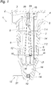
- an inlet 2 for the liquid 3 to be filtered, in particular drinking water, and an outlet 4 for the filtered liquid 5 can be seen.
- a cartridge-shaped filter 6, 106 is provided in the backwash filter 1 or 101, which inserts the housing 7 of the backwash filter 1, 101 into an inlet chamber 8 connected to the inlet 2 and into an outlet chamber 9 connected to the outlet 4 divided.
- the housing 7 of the backwash filter 1, 101 is formed by an upper part 7.1 and a filter bell 7.2 that can be detached from the upper part 7.1.
- 2 is for backwashing the backwash filter 1, 101, this equipped with an outlet 10, via which outlet 10 the in 2 or.
- This liquid 11 to be discharged is removed by the backflushing device 12 in the region of the inlet chamber 8 , for which purpose the backflushing device 12 has, among other things, a suction element 13 or 113 in the inlet chamber 8 .
- This suction element 13 or 113 can be rotated about the filter 6, 106, preferably freely, and has a plurality of suction openings 14 which are directed towards the filter 6, 106 in the suction direction 15 for filter cleaning, as is shown in 3 for the first suction element 13 of the first backflush filter 1 is shown in a full section section according to III-III perpendicular to its longitudinal axis. This 3 also applies to the second suction element 113 of the second backwash filter 101 with a kinked section according to III-III figure 5 .
- the backwashing device 12 is also assigned a rotary device 17, with which the suction element 13, 113 can be driven in rotation - namely by using a pressure drop in the backwashing channel 16, which pressure drop occurs during backwashing in the backwashing channel 16 when the backwash valve 18 is opened.
- the rotary movement of the suction element 13, 113 is generated by the rotary device 17 in that the suction directions 15 of the suction openings 14 are inclined relative to the radial line 19 of the suction element 13, 113 - as is shown in 3 can be seen from the angle of inclination 20 between the suction direction 15 and the radial line 19 in the horizontal or a horizontal plane.
- Suction directions 15 can generate a reaction torque acting on the suction element 13, 113, which causes the suction element 13, 113, which is freely rotatably mounted in the backwash filter 1, 101, to rotate.
- the force directions or suction directions 15 of the liquid 11 discharged via the suction openings 14 do not intersect the bearing axis 37 about which the suction element 13, 113 rotates, but are offset by 50 degrees, for example, with respect to the radial 19, which means that the suction element 13, 113 a torque acts.
- the suction openings 14 of the first suction element 13 are designed in the form of a slot or as a slot 22 and run in a helix shape on the jacket 21 of the first suction element 13. which can improve the suction on the filter 6, especially when stubbornly adhering dirt particles are to be sucked off the filter 6.
- the two slot-shaped suction openings 14 and slot 22 are also on the first suction element 13 diametrically opposite.
- the second suction element 113 shown in detail in front and rear view shows in contrast to 4 suction element 13 shown several rows 122.1 and 122.2 on suction openings 14, which are arranged one after the other and at a distance from one another.
- the rows 122.1 and 122.2 run inclined to the longitudinal axis 23 of the second suction element 13 over their entire length 124.
- the suction openings 14 of the two diametrically opposite rows 122.1, 122.2 are also arranged with a gap 141 in relation to one another, which enables the dirt particles to be ripped away particularly well from the filter 106.
- the suction element 13, 113 is arranged coaxially in the filter 6, 106, as is the case, for example, in FIG figure 2 or 4 can be recognized--this coaxial arrangement can also ensure particularly uniform cleaning of the filter 6, 106.
- the backwash channel 16 has in the suction element 13, 113 a middle central channel 25 and a plurality of side channels 26 connected to the middle central channel 25, which is shown in FIG 3 is shown in more detail.
- the side channels 26 run inclined towards the radial line 20 of the suction element 13, 113 and end in the respective suction opening 14. Because these side channels 26 are opposite one another and have curved guide surfaces 27, 28 which end at the suction opening 14, a nozzle-shaped suction jet can be directed into Suction directions 15 are generated, which additionally increases the driving force for the rotation of the suction element 13, 113.
- the central channel 25 widens longitudinally in its cross-sectional area 29--namely, it becomes larger in its cross-sectional area 29 in the direction of the outflow 10.
- FIG. Uniform suction over the entire suction opening 14 is thus achieved.
- the suction element 13, 113 also has two forward-curved blades 30 in order to form the suction element 14 as a blade wheel, as shown in FIG figure 3 can be recognized.
- the suction element 13 , 113 can also remove kinetic energy in the flow path between the inlet 2 and the outlet 4 in the manner of an impulse turbine and use this to drive the rotational movement of the suction element 13 .
- the rotation of the suction element 13, 113 and thus a functional suction of the filter 6, 106 are maintained.
- the two blades 30 have their respective intake opening 14 on their blade edge 32, which avoids braking turbulence at these points and thus facilitates the rotation of the suction element 13, 113.
- the blade contour of blade 30 varies in the longitudinal direction of suction element 13, 113.
- the suction element 13, 113 is mounted in the backwash filter 1 so that it can be displaced axially from a filter operating position 33 into a backwash position 34, namely axially along the bearing axis 37, about which the suction element 13 is also rotatably mounted. Since the suction element 13, 113 is mounted in the backwash filter 1 so that it can be displaced axially against the spring force of a restoring spring 38, 138, the suction element 13 can be moved back from the backwash position 34 to the filter operating position 33 in a structurally simple manner even after the backwash filter 1 has been backwashed.
- the seat of the pressing return spring 38 is formed between the open filter cover 39 of the filter 6 and an annular disk 40 inserted in the first suction element 13 .
- the seat of the pressing return spring 138 is formed between the bottom 36 of the inlet chamber 8 and a guide rod 140 which is mounted in the bottom 36 in a linearly displaceable manner.
- the open filter cover 139 here forms a bushing 142 as an abutment for the bolt-shaped end of the suction element 113 .
- This axial displaceability also allows an outlet opening 35, 135 to be opened or closed, which is conducive to quick and stable cleaning of the filter 6, 106.
- first outlet openings 35 are connected to the backwash channel 12 and are arranged relative to the base 36 of the inlet chamber 8 in such a way that, on the one hand, in the filter operating position 33, these first outlet openings 35 are above the base 36 of the inlet chamber 8 and are therefore open to the inlet chamber 8 and on the other hand, in the backwash position 12 that is axially displaced with respect to the filter operating position 33 , these outlet openings 35 lie below the floor 36 of the inlet chamber 8 and are therefore closed with respect to the inlet chamber 8 .
- contaminants can already be discharged into a pressure chamber 27 located below the inlet chamber 8—thus protecting the suction openings 14 from being blocked by larger contaminants.
- the second outlet opening 135 is formed between the second suction element 113 and the base 36 of the inlet chamber 8 - for this purpose the second suction element 113 in its filter operating position 33 at a distance from the floor 36 .
- the second suction element 113 rests on the floor 36 , which closes the second outlet opening 135 .
Landscapes
- Chemical & Material Sciences (AREA)
- Chemical Kinetics & Catalysis (AREA)
- Filtering Of Dispersed Particles In Gases (AREA)
- Filtration Of Liquid (AREA)
- Structures Of Non-Positive Displacement Pumps (AREA)
Claims (15)
- Filtre à rétrolavage comprenant une entrée (2), une sortie (4) et un écoulement (10), un filtre (6, 106), un boîtier (7) qui est divisé par le filtre (6, 106) en une chambre d'entrée (8) reliée à l'entrée (2) et en une chambre de sortie (9) reliée à la sortie (4), et un dispositif de rétrolavage (12) qui comprend à la fois un élément d'aspiration (13, 113) disposé dans le boîtier (7) de manière à pouvoir tourner autour du filtre (6, 106) côté entrée, doté au moins d'un orifice d'aspiration (14) qui est tourné vers le filtre (6, 106) pour le nettoyage du filtre dans la direction d'aspiration (15), et un conduit de rétrolavage (16) relié à l'orifice d'aspiration (14) et à un écoulement (10), et un dispositif de rotation (17) qui, lors d'une chute de pression dans le conduit de rétrolavage (16), entraîne le mouvement de rotation de l'élément d'aspiration (13, 113) autour du filtre (6, 106), le dispositif de rotation (17) entraînant, lors de la chute de pression dans le conduit de rétrolavage (16), le mouvement de rotation de l'élément d'aspiration (13, 113) par la direction d'aspiration (15) de l'orifice d'aspiration (14), inclinée par rapport à la direction radiale (19) de l'élément d'aspiration (13, 113),
caractérisé en ce que l'élément d'aspiration (13, 113) est monté dans le filtre à rétrolavage de manière à pouvoir être déplacé d'une position de fonctionnement du filtre (33) dans une position de rétrolavage (34) axialement le long d'un axe de palier (37) autour duquel l'élément d'aspiration (13, 113) est monté sur pivot, et le filtre à rétrolavage (1, 101) comportant une ouverture de sortie (35, 135) reliée au conduit de rétrolavage (16) qui, d'une part, est ouverte par rapport à la chambre d'entrée (8) dans la position de fonctionnement du filtre (33) de l'élément d'aspiration (13, 113) et, d'autre part, est fermée par rapport à la chambre d'entrée (8) dans la position de rétrolavage (34) de l'élément d'aspiration (13, 113), déplacée axialement par rapport à la position de fonctionnement du filtre (33). - Filtre à rétrolavage selon la revendication 1, caractérisé en ce que l'orifice d'aspiration (14) est conçu en forme de fente.
- Filtre à rétrolavage selon la revendication 2, caractérisé en ce que l'axe longitudinal de la fente (22.1) de l'orifice d'aspiration (14) est incliné par rapport à l'axe longitudinal (23) de l'élément d'aspiration (13).
- Filtre à rétrolavage selon la revendication 1, caractérisé en ce que l'élément d'aspiration (113) comporte au moins une rangée (122.1, 122.2) d'orifices d'aspiration (14) disposés les uns après les autres et espacés les uns des autres, passant le long de celui-ci.
- Filtre à rétrolavage selon la revendication 4, caractérisé en ce que l'élément d'aspiration (113) comporte deux rangées (122.1, 122.2) diamétralement opposées, dont les orifices d'aspiration (14) sont disposés sur des espaces (141) les uns par rapport aux autres.
- Filtre à rétrolavage selon l'une des revendications 1 à 5, caractérisé en ce que l'élément d'aspiration (13, 113) et le filtre (6, 106) sont disposés coaxialement l'un par rapport à l'autre.
- Filtre à rétrolavage selon l'une des revendications 1 à 6, caractérisé en ce que le conduit de rétrolavage (16) comporte un canal central médian (25) dans l'élément d'aspiration (13, 113) et au moins un canal latéral (26) relié au canal central médian (25), qui est incliné par rapport à la direction radiale (19) de l'élément d'aspiration (13, 113) et se termine dans l'orifice d'aspiration (14).
- Filtre à rétrolavage selon la revendication 7, caractérisé en ce que le canal latéral (26) comporte des surfaces de guidage incurvées (27, 28), opposées les uns par rapport aux autres et se terminant au niveau de l'orifice d'aspiration (14).
- Filtre à rétrolavage selon la revendication 7 ou 8, caractérisé en ce que le canal central (25) s'étend dans sa section transversale (29) en direction de l'écoulement (10) .
- Filtre à rétrolavage selon l'une des revendications 1 à 9, caractérisé en ce que l'élément d'aspiration (13, 113) comporte au moins une pale (30).
- Filtre à rétrolavage selon la revendication 10, caractérisé en ce que la pale (30) comporte l'orifice d'aspiration (14) au niveau de son bord (32).
- Filtre à rétrolavage selon la revendication 10 ou 11, caractérisé en ce que la pale (30) est incurvée vers l'avant.
- Filtre à rétrolavage selon la revendication 10, 11 ou 12, caractérisé en ce que le contour de la pale (30) varie dans le sens de la longueur de l'élément d'aspiration (13, 113) .
- Filtre à rétrolavage selon l'une des revendications 1 à 13, caractérisé en ce que l'élément d'aspiration (13, 113) est disposé de manière à pouvoir tourner librement dans le filtre à rétrolavage (1).
- Filtre à rétrolavage selon l'une des revendications précédentes, caractérisé en ce que l'élément d'aspiration (13, 113) est monté de manière à pouvoir être déplacé axialement contre un ressort de rappel (38, 138) dans le filtre à rétrolavage (1).
Applications Claiming Priority (2)
| Application Number | Priority Date | Filing Date | Title |
|---|---|---|---|
| EP16177668.7A EP3263203A1 (fr) | 2016-07-01 | 2016-07-01 | Filtre de retrolavage |
| PCT/EP2017/066532 WO2018002384A1 (fr) | 2016-07-01 | 2017-07-03 | Filtre à rétrolavage |
Publications (2)
| Publication Number | Publication Date |
|---|---|
| EP3478389A1 EP3478389A1 (fr) | 2019-05-08 |
| EP3478389B1 true EP3478389B1 (fr) | 2022-11-09 |
Family
ID=56418373
Family Applications (2)
| Application Number | Title | Priority Date | Filing Date |
|---|---|---|---|
| EP16177668.7A Withdrawn EP3263203A1 (fr) | 2016-07-01 | 2016-07-01 | Filtre de retrolavage |
| EP17743264.8A Active EP3478389B1 (fr) | 2016-07-01 | 2017-07-03 | Filtre de retrolavage |
Family Applications Before (1)
| Application Number | Title | Priority Date | Filing Date |
|---|---|---|---|
| EP16177668.7A Withdrawn EP3263203A1 (fr) | 2016-07-01 | 2016-07-01 | Filtre de retrolavage |
Country Status (5)
| Country | Link |
|---|---|
| US (1) | US11957999B2 (fr) |
| EP (2) | EP3263203A1 (fr) |
| CN (1) | CN109562306B (fr) |
| RU (1) | RU2744887C2 (fr) |
| WO (1) | WO2018002384A1 (fr) |
Families Citing this family (6)
| Publication number | Priority date | Publication date | Assignee | Title |
|---|---|---|---|---|
| DE102017008810A1 (de) | 2017-09-20 | 2019-03-21 | Cetteen Gmbh | MBFEX-Röhre |
| EP3810301A4 (fr) * | 2018-06-25 | 2022-02-23 | Peter Hoefler | Filtres rotatifs et systèmes associés |
| DK201870747A1 (en) | 2018-11-14 | 2020-06-23 | Bollfilter Nordic Aps | Filter candle and method for operating such filter candle |
| CN111514636B (zh) * | 2020-04-29 | 2021-11-02 | 山东超华环保智能装备有限公司 | 一种污水后续净化处理装置 |
| GB2617537B (en) * | 2022-01-07 | 2024-07-31 | Indufil BV | Filter system with backflush |
| US12427453B2 (en) * | 2022-11-25 | 2025-09-30 | Samsung Electronics Co., Ltd. | Microplastic filter for washing machines or other appliances |
Citations (1)
| Publication number | Priority date | Publication date | Assignee | Title |
|---|---|---|---|---|
| DE8438010U1 (de) * | 1984-12-24 | 1986-04-03 | August G. Koch Maschinenfabrik, 2300 Kiel | Flüssigkeitsfilter mit hydraulisch angetriebener Rückspülvorrichtung |
Family Cites Families (15)
| Publication number | Priority date | Publication date | Assignee | Title |
|---|---|---|---|---|
| GB1485989A (en) | 1975-05-23 | 1977-09-14 | Plenty Group Ltd | Filter with backflushing device |
| IT1235896B (it) * | 1989-11-24 | 1992-11-25 | Gel Srl | Filtro autopulente per impianti idrici, corredato di turbinetta idraulica per l'azionamento di alcune spazzole pulenti |
| SU1724316A1 (ru) | 1989-12-04 | 1992-04-07 | Воронежский инженерно-строительный институт | Самоочищающийс фильтр |
| DE4343180A1 (de) | 1993-12-17 | 1995-06-22 | Alpha Vogt Gmbh & Co Schwimmba | Rückspülbares Filter |
| JPH11314015A (ja) * | 1998-05-06 | 1999-11-16 | Tadayoshi Nagaoka | 濾過装置 |
| DE29809202U1 (de) | 1998-05-22 | 1998-07-30 | Boll & Kirch Filterbau GmbH, 50170 Kerpen | Rückspülfilter |
| DE10024401A1 (de) * | 2000-05-19 | 2001-11-22 | Boll & Kirch Filter | Rückspulfilter, insbesondere für die Schmierölfilterung |
| US8329037B2 (en) * | 2000-08-17 | 2012-12-11 | Carew E Bayne | Filter apparatus and method of removing organic waste |
| CN1302830C (zh) * | 2003-08-19 | 2007-03-07 | 汉斯萨塞拉思有限责任公司 | 带有反向漂洗装置的过滤器装置 |
| CN1887401A (zh) * | 2006-06-06 | 2007-01-03 | 孙结实 | 鼠笼滤筒动态连续抽吸过滤机 |
| AT504361B8 (de) * | 2007-01-18 | 2008-09-15 | Chemiefaser Lenzing Ag | Rückspülfilter |
| SG174635A1 (en) | 2010-03-08 | 2011-10-28 | Aalborg Ind Water Treat Pte Ltd | Self-cleaning filter module |
| KR101287090B1 (ko) | 2011-10-13 | 2013-07-17 | 주식회사 파나시아 | 고밀도 필터 구조의 고효율 캔들 타입 밸러스트수 여과장치 |
| US10286338B2 (en) * | 2014-01-13 | 2019-05-14 | Spiral Water Technologies, Inc. | Flow control features for fluid filtration device and methods |
| DE202016101180U1 (de) * | 2016-03-04 | 2017-06-07 | Hans Sasserath Gmbh & Co. Kg | Druckminderer-Filter-Anordnung |
-
2016
- 2016-07-01 EP EP16177668.7A patent/EP3263203A1/fr not_active Withdrawn
-
2017
- 2017-07-03 US US16/314,286 patent/US11957999B2/en active Active
- 2017-07-03 EP EP17743264.8A patent/EP3478389B1/fr active Active
- 2017-07-03 CN CN201780040990.3A patent/CN109562306B/zh active Active
- 2017-07-03 WO PCT/EP2017/066532 patent/WO2018002384A1/fr not_active Ceased
- 2017-07-03 RU RU2019102659A patent/RU2744887C2/ru active
Patent Citations (1)
| Publication number | Priority date | Publication date | Assignee | Title |
|---|---|---|---|---|
| DE8438010U1 (de) * | 1984-12-24 | 1986-04-03 | August G. Koch Maschinenfabrik, 2300 Kiel | Flüssigkeitsfilter mit hydraulisch angetriebener Rückspülvorrichtung |
Also Published As
| Publication number | Publication date |
|---|---|
| WO2018002384A1 (fr) | 2018-01-04 |
| EP3263203A1 (fr) | 2018-01-03 |
| CN109562306B (zh) | 2021-10-01 |
| RU2019102659A (ru) | 2020-08-03 |
| RU2019102659A3 (fr) | 2020-09-08 |
| EP3478389A1 (fr) | 2019-05-08 |
| CN109562306A (zh) | 2019-04-02 |
| US11957999B2 (en) | 2024-04-16 |
| RU2744887C2 (ru) | 2021-03-16 |
| US20190201818A1 (en) | 2019-07-04 |
Similar Documents
| Publication | Publication Date | Title |
|---|---|---|
| EP3478389B1 (fr) | Filtre de retrolavage | |
| DE1528763C3 (de) | Kreiselpumpe | |
| EP3368773B1 (fr) | Dispositif d'aspiration d'air pour une hotte aspirante | |
| DE2938003A1 (de) | Filteranordnung | |
| EP0293515A2 (fr) | Dispositif pour enlever des solides d'un liquide coulant dans un égout | |
| WO2012079993A2 (fr) | Dispositif de filtration continue de mélanges de matières | |
| EP2201993A1 (fr) | Filtre à fluide | |
| EP2950932B1 (fr) | Centrifugeuse à vis à bol plein dotée d'un bord faisant barrage | |
| EP3779201B1 (fr) | Élément de raclage pour bords d'attaque de roue à aubes pour des pompes à eau | |
| DE102005031420A1 (de) | Kombinierte Tauch-/Flachabsaug-Rotationspumpe | |
| EP2188532A1 (fr) | Roue à aubes de pompe et pompe comprenant une telle roue à aubes de pompe | |
| WO2012069619A1 (fr) | Plaque de fermeture autonettoyante dans une pompe à écoulement radial | |
| WO2016162087A1 (fr) | Pompe submersible à préfiltre | |
| EP2497956A1 (fr) | Pompe à tourbillon | |
| DE202020107208U1 (de) | Verteilervorrichtung zum Verteilen von feststoffhaltigen Flüssigkeiten | |
| DE3340295A1 (de) | Pumpe zum foerdern von mit stueckigen verunreinigungen durchsetzten fluessigkeiten | |
| WO2001074492A2 (fr) | Centrifugeuse a surfaces de separation orientees axialement | |
| EP3252312A1 (fr) | Soupape d'échappement/anti-retour pour une pompe à vide | |
| CH679131A5 (en) | Surface-spraying machine - has guide casing enclosing slewing nozzle ring | |
| DE2757746A1 (de) | Vorrichtung zum aufbereiten einer suspension | |
| DE102005015534B3 (de) | Vorrichtung zur Reinigung von Behältern | |
| DE202017103543U1 (de) | Filterpatrone eines Staubabscheiders mit Entstaubungsvorrichtung | |
| DE3718425C2 (de) | Pumpe, insbesondere Faßpumpe | |
| DE102014004420A1 (de) | Kreiselpumpe mit Schneidvorrichtung | |
| DE3733307C2 (de) | Pumpe, insbesondere Faßpumpe |
Legal Events
| Date | Code | Title | Description |
|---|---|---|---|
| STAA | Information on the status of an ep patent application or granted ep patent |
Free format text: STATUS: UNKNOWN |
|
| STAA | Information on the status of an ep patent application or granted ep patent |
Free format text: STATUS: THE INTERNATIONAL PUBLICATION HAS BEEN MADE |
|
| PUAI | Public reference made under article 153(3) epc to a published international application that has entered the european phase |
Free format text: ORIGINAL CODE: 0009012 |
|
| STAA | Information on the status of an ep patent application or granted ep patent |
Free format text: STATUS: REQUEST FOR EXAMINATION WAS MADE |
|
| 17P | Request for examination filed |
Effective date: 20190201 |
|
| AK | Designated contracting states |
Kind code of ref document: A1 Designated state(s): AL AT BE BG CH CY CZ DE DK EE ES FI FR GB GR HR HU IE IS IT LI LT LU LV MC MK MT NL NO PL PT RO RS SE SI SK SM TR |
|
| AX | Request for extension of the european patent |
Extension state: BA ME |
|
| DAV | Request for validation of the european patent (deleted) | ||
| DAX | Request for extension of the european patent (deleted) | ||
| STAA | Information on the status of an ep patent application or granted ep patent |
Free format text: STATUS: EXAMINATION IS IN PROGRESS |
|
| 17Q | First examination report despatched |
Effective date: 20191211 |
|
| GRAP | Despatch of communication of intention to grant a patent |
Free format text: ORIGINAL CODE: EPIDOSNIGR1 |
|
| STAA | Information on the status of an ep patent application or granted ep patent |
Free format text: STATUS: GRANT OF PATENT IS INTENDED |
|
| GRAS | Grant fee paid |
Free format text: ORIGINAL CODE: EPIDOSNIGR3 |
|
| GRAA | (expected) grant |
Free format text: ORIGINAL CODE: 0009210 |
|
| STAA | Information on the status of an ep patent application or granted ep patent |
Free format text: STATUS: THE PATENT HAS BEEN GRANTED |
|
| INTG | Intention to grant announced |
Effective date: 20220916 |
|
| AK | Designated contracting states |
Kind code of ref document: B1 Designated state(s): AL AT BE BG CH CY CZ DE DK EE ES FI FR GB GR HR HU IE IS IT LI LT LU LV MC MK MT NL NO PL PT RO RS SE SI SK SM TR |
|
| REG | Reference to a national code |
Ref country code: GB Ref legal event code: FG4D Free format text: NOT ENGLISH |
|
| REG | Reference to a national code |
Ref country code: CH Ref legal event code: EP Ref country code: AT Ref legal event code: REF Ref document number: 1529984 Country of ref document: AT Kind code of ref document: T Effective date: 20221115 |
|
| REG | Reference to a national code |
Ref country code: DE Ref legal event code: R096 Ref document number: 502017014073 Country of ref document: DE |
|
| REG | Reference to a national code |
Ref country code: IE Ref legal event code: FG4D Free format text: LANGUAGE OF EP DOCUMENT: GERMAN |
|
| REG | Reference to a national code |
Ref country code: LT Ref legal event code: MG9D |
|
| RAP4 | Party data changed (patent owner data changed or rights of a patent transferred) |
Owner name: BWT HOLDING GMBH |
|
| REG | Reference to a national code |
Ref country code: NL Ref legal event code: MP Effective date: 20221109 |
|
| PG25 | Lapsed in a contracting state [announced via postgrant information from national office to epo] |
Ref country code: SE Free format text: LAPSE BECAUSE OF FAILURE TO SUBMIT A TRANSLATION OF THE DESCRIPTION OR TO PAY THE FEE WITHIN THE PRESCRIBED TIME-LIMIT Effective date: 20221109 Ref country code: PT Free format text: LAPSE BECAUSE OF FAILURE TO SUBMIT A TRANSLATION OF THE DESCRIPTION OR TO PAY THE FEE WITHIN THE PRESCRIBED TIME-LIMIT Effective date: 20230309 Ref country code: NO Free format text: LAPSE BECAUSE OF FAILURE TO SUBMIT A TRANSLATION OF THE DESCRIPTION OR TO PAY THE FEE WITHIN THE PRESCRIBED TIME-LIMIT Effective date: 20230209 Ref country code: LT Free format text: LAPSE BECAUSE OF FAILURE TO SUBMIT A TRANSLATION OF THE DESCRIPTION OR TO PAY THE FEE WITHIN THE PRESCRIBED TIME-LIMIT Effective date: 20221109 Ref country code: FI Free format text: LAPSE BECAUSE OF FAILURE TO SUBMIT A TRANSLATION OF THE DESCRIPTION OR TO PAY THE FEE WITHIN THE PRESCRIBED TIME-LIMIT Effective date: 20221109 Ref country code: ES Free format text: LAPSE BECAUSE OF FAILURE TO SUBMIT A TRANSLATION OF THE DESCRIPTION OR TO PAY THE FEE WITHIN THE PRESCRIBED TIME-LIMIT Effective date: 20221109 |
|
| PG25 | Lapsed in a contracting state [announced via postgrant information from national office to epo] |
Ref country code: RS Free format text: LAPSE BECAUSE OF FAILURE TO SUBMIT A TRANSLATION OF THE DESCRIPTION OR TO PAY THE FEE WITHIN THE PRESCRIBED TIME-LIMIT Effective date: 20221109 Ref country code: PL Free format text: LAPSE BECAUSE OF FAILURE TO SUBMIT A TRANSLATION OF THE DESCRIPTION OR TO PAY THE FEE WITHIN THE PRESCRIBED TIME-LIMIT Effective date: 20221109 Ref country code: LV Free format text: LAPSE BECAUSE OF FAILURE TO SUBMIT A TRANSLATION OF THE DESCRIPTION OR TO PAY THE FEE WITHIN THE PRESCRIBED TIME-LIMIT Effective date: 20221109 Ref country code: IS Free format text: LAPSE BECAUSE OF FAILURE TO SUBMIT A TRANSLATION OF THE DESCRIPTION OR TO PAY THE FEE WITHIN THE PRESCRIBED TIME-LIMIT Effective date: 20230309 Ref country code: HR Free format text: LAPSE BECAUSE OF FAILURE TO SUBMIT A TRANSLATION OF THE DESCRIPTION OR TO PAY THE FEE WITHIN THE PRESCRIBED TIME-LIMIT Effective date: 20221109 Ref country code: GR Free format text: LAPSE BECAUSE OF FAILURE TO SUBMIT A TRANSLATION OF THE DESCRIPTION OR TO PAY THE FEE WITHIN THE PRESCRIBED TIME-LIMIT Effective date: 20230210 |
|
| PG25 | Lapsed in a contracting state [announced via postgrant information from national office to epo] |
Ref country code: NL Free format text: LAPSE BECAUSE OF FAILURE TO SUBMIT A TRANSLATION OF THE DESCRIPTION OR TO PAY THE FEE WITHIN THE PRESCRIBED TIME-LIMIT Effective date: 20221109 |
|
| P01 | Opt-out of the competence of the unified patent court (upc) registered |
Effective date: 20230525 |
|
| PG25 | Lapsed in a contracting state [announced via postgrant information from national office to epo] |
Ref country code: SM Free format text: LAPSE BECAUSE OF FAILURE TO SUBMIT A TRANSLATION OF THE DESCRIPTION OR TO PAY THE FEE WITHIN THE PRESCRIBED TIME-LIMIT Effective date: 20221109 Ref country code: RO Free format text: LAPSE BECAUSE OF FAILURE TO SUBMIT A TRANSLATION OF THE DESCRIPTION OR TO PAY THE FEE WITHIN THE PRESCRIBED TIME-LIMIT Effective date: 20221109 Ref country code: EE Free format text: LAPSE BECAUSE OF FAILURE TO SUBMIT A TRANSLATION OF THE DESCRIPTION OR TO PAY THE FEE WITHIN THE PRESCRIBED TIME-LIMIT Effective date: 20221109 Ref country code: DK Free format text: LAPSE BECAUSE OF FAILURE TO SUBMIT A TRANSLATION OF THE DESCRIPTION OR TO PAY THE FEE WITHIN THE PRESCRIBED TIME-LIMIT Effective date: 20221109 Ref country code: CZ Free format text: LAPSE BECAUSE OF FAILURE TO SUBMIT A TRANSLATION OF THE DESCRIPTION OR TO PAY THE FEE WITHIN THE PRESCRIBED TIME-LIMIT Effective date: 20221109 |
|
| REG | Reference to a national code |
Ref country code: DE Ref legal event code: R097 Ref document number: 502017014073 Country of ref document: DE |
|
| PG25 | Lapsed in a contracting state [announced via postgrant information from national office to epo] |
Ref country code: SK Free format text: LAPSE BECAUSE OF FAILURE TO SUBMIT A TRANSLATION OF THE DESCRIPTION OR TO PAY THE FEE WITHIN THE PRESCRIBED TIME-LIMIT Effective date: 20221109 Ref country code: AL Free format text: LAPSE BECAUSE OF FAILURE TO SUBMIT A TRANSLATION OF THE DESCRIPTION OR TO PAY THE FEE WITHIN THE PRESCRIBED TIME-LIMIT Effective date: 20221109 |
|
| PLBE | No opposition filed within time limit |
Free format text: ORIGINAL CODE: 0009261 |
|
| STAA | Information on the status of an ep patent application or granted ep patent |
Free format text: STATUS: NO OPPOSITION FILED WITHIN TIME LIMIT |
|
| 26N | No opposition filed |
Effective date: 20230810 |
|
| PG25 | Lapsed in a contracting state [announced via postgrant information from national office to epo] |
Ref country code: SI Free format text: LAPSE BECAUSE OF FAILURE TO SUBMIT A TRANSLATION OF THE DESCRIPTION OR TO PAY THE FEE WITHIN THE PRESCRIBED TIME-LIMIT Effective date: 20221109 |
|
| PG25 | Lapsed in a contracting state [announced via postgrant information from national office to epo] |
Ref country code: MC Free format text: LAPSE BECAUSE OF FAILURE TO SUBMIT A TRANSLATION OF THE DESCRIPTION OR TO PAY THE FEE WITHIN THE PRESCRIBED TIME-LIMIT Effective date: 20221109 |
|
| PG25 | Lapsed in a contracting state [announced via postgrant information from national office to epo] |
Ref country code: MC Free format text: LAPSE BECAUSE OF FAILURE TO SUBMIT A TRANSLATION OF THE DESCRIPTION OR TO PAY THE FEE WITHIN THE PRESCRIBED TIME-LIMIT Effective date: 20221109 |
|
| REG | Reference to a national code |
Ref country code: BE Ref legal event code: MM Effective date: 20230731 |
|
| PG25 | Lapsed in a contracting state [announced via postgrant information from national office to epo] |
Ref country code: LU Free format text: LAPSE BECAUSE OF NON-PAYMENT OF DUE FEES Effective date: 20230703 |
|
| GBPC | Gb: european patent ceased through non-payment of renewal fee |
Effective date: 20230703 |
|
| PG25 | Lapsed in a contracting state [announced via postgrant information from national office to epo] |
Ref country code: LU Free format text: LAPSE BECAUSE OF NON-PAYMENT OF DUE FEES Effective date: 20230703 |
|
| REG | Reference to a national code |
Ref country code: IE Ref legal event code: MM4A |
|
| PG25 | Lapsed in a contracting state [announced via postgrant information from national office to epo] |
Ref country code: GB Free format text: LAPSE BECAUSE OF NON-PAYMENT OF DUE FEES Effective date: 20230703 |
|
| PG25 | Lapsed in a contracting state [announced via postgrant information from national office to epo] |
Ref country code: IT Free format text: LAPSE BECAUSE OF FAILURE TO SUBMIT A TRANSLATION OF THE DESCRIPTION OR TO PAY THE FEE WITHIN THE PRESCRIBED TIME-LIMIT Effective date: 20221109 Ref country code: FR Free format text: LAPSE BECAUSE OF NON-PAYMENT OF DUE FEES Effective date: 20230731 Ref country code: BE Free format text: LAPSE BECAUSE OF NON-PAYMENT OF DUE FEES Effective date: 20230731 |
|
| PG25 | Lapsed in a contracting state [announced via postgrant information from national office to epo] |
Ref country code: IE Free format text: LAPSE BECAUSE OF NON-PAYMENT OF DUE FEES Effective date: 20230703 |
|
| PG25 | Lapsed in a contracting state [announced via postgrant information from national office to epo] |
Ref country code: IE Free format text: LAPSE BECAUSE OF NON-PAYMENT OF DUE FEES Effective date: 20230703 |
|
| PG25 | Lapsed in a contracting state [announced via postgrant information from national office to epo] |
Ref country code: BG Free format text: LAPSE BECAUSE OF FAILURE TO SUBMIT A TRANSLATION OF THE DESCRIPTION OR TO PAY THE FEE WITHIN THE PRESCRIBED TIME-LIMIT Effective date: 20221109 |
|
| PG25 | Lapsed in a contracting state [announced via postgrant information from national office to epo] |
Ref country code: BG Free format text: LAPSE BECAUSE OF FAILURE TO SUBMIT A TRANSLATION OF THE DESCRIPTION OR TO PAY THE FEE WITHIN THE PRESCRIBED TIME-LIMIT Effective date: 20221109 |
|
| PG25 | Lapsed in a contracting state [announced via postgrant information from national office to epo] |
Ref country code: CY Free format text: LAPSE BECAUSE OF FAILURE TO SUBMIT A TRANSLATION OF THE DESCRIPTION OR TO PAY THE FEE WITHIN THE PRESCRIBED TIME-LIMIT; INVALID AB INITIO Effective date: 20170703 |
|
| PG25 | Lapsed in a contracting state [announced via postgrant information from national office to epo] |
Ref country code: HU Free format text: LAPSE BECAUSE OF FAILURE TO SUBMIT A TRANSLATION OF THE DESCRIPTION OR TO PAY THE FEE WITHIN THE PRESCRIBED TIME-LIMIT; INVALID AB INITIO Effective date: 20170703 |
|
| PGFP | Annual fee paid to national office [announced via postgrant information from national office to epo] |
Ref country code: DE Payment date: 20250722 Year of fee payment: 9 |
|
| PGFP | Annual fee paid to national office [announced via postgrant information from national office to epo] |
Ref country code: AT Payment date: 20250721 Year of fee payment: 9 |
|
| PGFP | Annual fee paid to national office [announced via postgrant information from national office to epo] |
Ref country code: CH Payment date: 20250801 Year of fee payment: 9 |
|
| PG25 | Lapsed in a contracting state [announced via postgrant information from national office to epo] |
Ref country code: TR Free format text: LAPSE BECAUSE OF FAILURE TO SUBMIT A TRANSLATION OF THE DESCRIPTION OR TO PAY THE FEE WITHIN THE PRESCRIBED TIME-LIMIT Effective date: 20221109 |