EP2951458B1 - Zylinder-kolben-einheit mit kolbendrossel - Google Patents
Zylinder-kolben-einheit mit kolbendrossel Download PDFInfo
- Publication number
- EP2951458B1 EP2951458B1 EP14717657.2A EP14717657A EP2951458B1 EP 2951458 B1 EP2951458 B1 EP 2951458B1 EP 14717657 A EP14717657 A EP 14717657A EP 2951458 B1 EP2951458 B1 EP 2951458B1
- Authority
- EP
- European Patent Office
- Prior art keywords
- piston
- cylinder
- passageway
- valve disc
- face
- Prior art date
- Legal status (The legal status is an assumption and is not a legal conclusion. Google has not performed a legal analysis and makes no representation as to the accuracy of the status listed.)
- Active
Links
Images


Classifications
-
- F—MECHANICAL ENGINEERING; LIGHTING; HEATING; WEAPONS; BLASTING
- F16—ENGINEERING ELEMENTS AND UNITS; GENERAL MEASURES FOR PRODUCING AND MAINTAINING EFFECTIVE FUNCTIONING OF MACHINES OR INSTALLATIONS; THERMAL INSULATION IN GENERAL
- F16F—SPRINGS; SHOCK-ABSORBERS; MEANS FOR DAMPING VIBRATION
- F16F9/00—Springs, vibration-dampers, shock-absorbers, or similarly-constructed movement-dampers using a fluid or the equivalent as damping medium
- F16F9/32—Details
- F16F9/34—Special valve constructions; Shape or construction of throttling passages
- F16F9/3405—Throttling passages in or on piston body, e.g. slots
-
- F—MECHANICAL ENGINEERING; LIGHTING; HEATING; WEAPONS; BLASTING
- F16—ENGINEERING ELEMENTS AND UNITS; GENERAL MEASURES FOR PRODUCING AND MAINTAINING EFFECTIVE FUNCTIONING OF MACHINES OR INSTALLATIONS; THERMAL INSULATION IN GENERAL
- F16F—SPRINGS; SHOCK-ABSORBERS; MEANS FOR DAMPING VIBRATION
- F16F9/00—Springs, vibration-dampers, shock-absorbers, or similarly-constructed movement-dampers using a fluid or the equivalent as damping medium
- F16F9/10—Springs, vibration-dampers, shock-absorbers, or similarly-constructed movement-dampers using a fluid or the equivalent as damping medium using liquid only; using a fluid of which the nature is immaterial
- F16F9/14—Devices with one or more members, e.g. pistons, vanes, moving to and fro in chambers and using throttling effect
- F16F9/16—Devices with one or more members, e.g. pistons, vanes, moving to and fro in chambers and using throttling effect involving only straight-line movement of the effective parts
- F16F9/18—Devices with one or more members, e.g. pistons, vanes, moving to and fro in chambers and using throttling effect involving only straight-line movement of the effective parts with a closed cylinder and a piston separating two or more working spaces therein
- F16F9/19—Devices with one or more members, e.g. pistons, vanes, moving to and fro in chambers and using throttling effect involving only straight-line movement of the effective parts with a closed cylinder and a piston separating two or more working spaces therein with a single cylinder and of single-tube type
-
- F—MECHANICAL ENGINEERING; LIGHTING; HEATING; WEAPONS; BLASTING
- F16—ENGINEERING ELEMENTS AND UNITS; GENERAL MEASURES FOR PRODUCING AND MAINTAINING EFFECTIVE FUNCTIONING OF MACHINES OR INSTALLATIONS; THERMAL INSULATION IN GENERAL
- F16F—SPRINGS; SHOCK-ABSORBERS; MEANS FOR DAMPING VIBRATION
- F16F9/00—Springs, vibration-dampers, shock-absorbers, or similarly-constructed movement-dampers using a fluid or the equivalent as damping medium
- F16F9/32—Details
- F16F9/34—Special valve constructions; Shape or construction of throttling passages
Definitions
- the invention relates to a cylinder-piston unit which comprises a cylinder and a guided therein by means of a piston rod, sealed against the cylinder inner wall, a displacement chamber delimiting a compensation chamber piston with at least one longitudinal opening, wherein in the compensation chamber or in VerdrDeutschunsgraum a by means of a compression spring supported compensating, at least against the cylinder inner wall sealed compensating piston is arranged and wherein a valve disc together with the displacement chamber side piston surface defines a passageway.
- the present invention is therefore based on the object to develop a cylinder-piston unit with high damping and braking power.
- the cross-sectional area of the passageway is multiplied by the reciprocal of the length of the passageway and the reciprocal of the average roughness R a of its boundary surfaces less than 50.
- the FIG. 1 shows a cylinder-piston unit (10), which is used for example as a hydraulic damper for decelerating linearly moving masses.
- the cylinder-piston unit (10) comprises a cylinder (11) in which a piston (61) guided by means of a piston rod (51) is provided. is movable.
- the disk-shaped piston (61) has on its circumferential surface (62) an annular groove (63) in which a sealing element (64), for example an O-ring (64) sits.
- the O-ring (64) abuts against the groove-free cylinder inner wall (12) and seals the piston (61) against it.
- the piston rod (51) protrudes with radial play through a cylinder head cover (13) through out of the cylinder (11).
- the piston rod head (52) has in the exemplary embodiment a circumferential annular groove (53).
- An annular insertion stop (16) secures the position of the cylinder head cover (13) in the axial direction.
- the cylinder head cover (13) in the exemplary embodiment comprises an outer shell (14), eg a protective shell.
- an elastically deformable receiving clamp (18) is arranged at concave cylinder bottom (17).
- the piston (61) delimits a displacement chamber (91) from a compensation chamber (92).
- the displacement chamber (91) is arranged on the side of the piston (61) facing away from the piston rod (51), while the compensation chamber (92) lies on the piston rod side.
- the displacement chamber (91) on the piston rod side and the compensation chamber (92) may be formed of a thermoplastic or thermosetting plastic, of a metallic material, etc.
- the diameter of the piston rod is between 30% and 35% of the diameter of the piston (61).
- a displaceable compensating piston (31) is arranged in the compensation chamber (92) of the cylinder (11) in the compensation chamber (92) of the cylinder (11) in the compensation chamber (92) of the cylinder (11) .
- a displaceable compensating piston (31) is arranged in the presentation of the Figures 1 and 2 sits the balance piston (31) with clearance (32) on the piston rod (51).
- an elastically deformable element (33) for example a compression spring (33) is arranged.
- the compression spring (33) engages around the piston rod (51) and is supported on the compensation piston (31) and in an annular groove (21) of the cylinder head cover (13).
- the outer diameter of the compression spring (33) rises from both spring ends to the center of the spring.
- the outer spring guide (22) forms a stroke limiter (23) for the balance piston (31).
- the compression spring (33) may be formed as a helical spring, disc spring, elastomer body, etc.
- the balance piston (31) has on its the piston (61) facing side a guide ring (34). This surrounds a receiving pin (35) of a sealing element (36).
- the sleeve-shaped sealing element (36) has an at least approximately cuboid cross-sectional area with an annular groove (37) pointing in the direction of the piston (61).
- An outer sealing element section (38) carries a circumferential outer sealing nose (41) arranged on the otherwise cylindrical peripheral surface (39). This sealing nose (41) is in the representation of Figures 1 and 2 to the inner wall (24) of a flared portion (25) of the cylinder (11) pressed.
- the expansion of the cylinder (11) is, for example, 8% relative to the cylinder inner diameter in the region (26) of the piston (61).
- the inner sealing member portion (42) has a cylindrical inner wall (43) with an inwardly facing circumferential sealing nose (44).
- the end face of the lower sealing element section (42) is offset from the piston-side end face of the sealing element (36) by 10% of the length of the sealing element (36) in the direction of the compensating piston (31).
- the inner sealing lug (44) is pressed against the circumferential surface (54) of the piston rod (51).
- the two sealing lugs (41, 44) are offset from one another in the longitudinal direction (93).
- the piston (61) is attached to the piston rod (51). For example, it is positively locked with this, glued, etc. However, the two parts can also be non-positively, cohesively, etc., connected to each other.
- the piston (61) can also be formed on the piston rod (51).
- the peripheral surface (64) of the piston (61) is - on both sides of the annular groove (63) - cylindrical.
- the diameter of the piston (61) in the exemplary embodiment is 7.35 millimeters.
- three apertures (65) oriented in the longitudinal direction (93) are arranged in the piston (61), cf. the Figures 2 . 5 and 6 , These connect the piston rod connection side (66) facing the piston rod (51) to the piston end face (67).
- the longitudinal openings (65) each have a kidney-shaped cross-sectional area and lie on the same pitch circle.
- the longitudinal openings (65) terminate in an annular channel (68) which is coaxial with the piston center line (69).
- the sum of the cross-sectional areas of the longitudinal openings (65) in a normal plane to the longitudinal direction (93) of the cylinder-piston unit (10) in the exemplary embodiment is 9.5% of the cross-sectional area of the piston (61) in the same plane.
- the sum of the cross-sectional areas may be between 3% and 15% of the cross-sectional area of the piston (61).
- the piston end face (67) includes an inner surface (71) disposed within the annular channel (68) and an outer surface (72) disposed outside the annular channel (68). In the embodiment of Figures 1 - 5 both surfaces (71, 72) lie in the same plane.
- the channel (73) in the outer surface (72) of the piston end face (67) embossed a channel (73).
- This has a depth of 0.16 millimeters and a width of 0.2 millimeters in this embodiment. It connects the annular channel (68) with the peripheral surface (62).
- the depth of the channel (73) corresponds to the depth of the annular channel (68).
- the channel (73) includes an angle of 45 degrees.
- the average roughness R a of the channel bottom (76) and the average roughness R a of the side of the channel (73) limiting surfaces (77) is 1.6 microns.
- the guide pin (74) carries a valve disc (81) which is displaceable between two end positions (82, 83) in the longitudinal direction (93) of the piston (61) relative thereto.
- a lift-off guard (84) prevents loss of the valve disc (81).
- the valve disc (81) has a constant thickness of, for example, 0.2 millimeters and in a plane normal to the longitudinal direction (93) has an annular cross-section.
- the valve disc (81) is made for example of an elastically bendable material.
- the piston-side surface (85) facing the piston (61) has, for example, the same average roughness value R a as the base surface (76) of the channel (73). However, it can also have, at least in regions, a higher or lower average roughness R a .
- the valve disc (81) can also be in said plane have triangular, polygonal, rectangular, etc. cross section. In the illustrated embodiment, the valve disc (81) is smaller than the area of the piston end face (67).
- the diameter of the valve disc (81) is 86% of the diameter of the piston (61).
- the covered by the valve disc (81) length of the channel (73) is thus 1.14 millimeters.
- the space bounded by the channel (73) and by the valve disc (81) will be referred to below as passageway (95).
- a dimensionless characteristic value In the embodiment, this is 17.5. This value can be in an interval between 0 and 50. In the embodiments described here it is between 1 and 40.
- the individual values of all passageways (95) are added, which are delimited by the piston end face (67) and the valve disc (81).
- the channel (73) can also be arranged on the valve disc (81). It is also conceivable, for example, a channel (73) on the piston side and offset, for example, a channel (73) in the valve disc (81) impress. Also further channels are conceivable.
- the offset of the channels (73) is in this case chosen so that their projections do not overlap in a plan view of the piston end face (67).
- the valve disc (81) is placed on the piston (61) and secured by the lift-off (84).
- the assembly unit with the piston (61) and the piston rod (51) is now inserted with the piston (61) ahead in the cylinder (11). Subsequently, the compensating piston sealing element (36) and the compensating piston (31) are pushed onto the piston rod (51). After pushing the spring (33) on the piston rod (51) of the cylinder head cover (13) is pushed onto the piston rod (51) and secured in the cylinder (11).
- the cylinder (11) During assembly of the cylinder-piston unit (10), the cylinder (11) by means of the receiving bracket (18) attached to one of two relatively movable components.
- the piston rod (51) engages with its annular groove (53) in the second of the two components or suggests - in one embodiment as a stop damper - to this.
- the piston rod (51) is loaded in the direction of the cylinder bottom (17).
- the piston (61) presses against the hydraulic oil (94), wherein the on the slide pin (74) linearly displaceable valve disc (81) is pressed against the piston end face (67).
- the connection of the annular channel (68) to the displacement chamber (91) is thereby reduced to the passageway (95).
- the big length - the one in the FIG. 5 illustrated passageway (95) is 25% longer than one radially arranged passageway - and the small cross section of the passageway (95) form a high resistance to the along the passageway (95) compressed oil.
- the flow velocity of the oil is severely throttled.
- Via the annular channel (68) the oil (94) displaced from the displacement chamber (91) passes into the longitudinal channels (65) and is conveyed through the latter into the compensation chamber (92).
- the oil displaces the sealing element (36) and the compensating piston (31) against the spring (33).
- the used interior (19) of the cylinder-piston unit (10) increases.
- the retraction speed of the piston rod (51) is greatly delayed.
- the cylinder-piston unit (10) achieves high damping and deceleration performance.
- the end position of the piston rod (51) during retraction is reached when either the piston (61) abuts the cylinder bottom (17) or when the compensation chamber (92) has reached its maximum volume. Besipiellus then the balance piston (31) on the cylinder head cover (13).
- the piston rod (51) is pulled in the direction of the cylinder head cover (13).
- the oil flows through the longitudinal channels (65).
- the valve disc (81) in the longitudinal direction (93) is displaced towards the anti-lifting device (84).
- the distance of the valve disc (81) to the piston end face (67) is increased.
- the oil now flows almost without resistance from the expansion chamber (92) in the displacement chamber (91).
- the stroke of the piston rod (51) is terminated when the piston (61) rests against the sealing element (36) and the compensating piston (31) has compressed the spring (33).
- the cylinder-piston unit (10) may also include an extension spring. This can be in be arranged the design of a compression spring in the displacement chamber or sitting in a design as a tension spring in the expansion chamber. It is also conceivable to arrange an extension spring acting on the piston rod (51) outside the cylinder (11) of the cylinder-piston unit (10). Such a cylinder-piston unit can be used as a stop damper.
- the compensating piston (31) in the displacement chamber (91). When decelerating then both the piston (61) and the balance piston (31) is moved. Depending on the design of the compensating piston spring (33), first the compensating piston (31) and then the piston throttle (65, 73) or first the piston throttle (65, 73) and then the compensating piston (31) respond. A simultaneous response is conceivable. With such a variant, a stroke and / or speed-dependent damping behavior can be achieved.
- the displacement chamber (91) can also be arranged on the piston rod side. For example, then sits the valve disc (81) piston rod side on the piston (61). For example, a channel (73) is then embossed in the piston end face (67) facing the displacement chamber (91).
- the compensating piston (31) can also be arranged in the compensation chamber (92) or in the displacement chamber (91) in this exemplary embodiment.
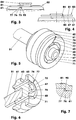
- FIG. 6 shows a dimetric longitudinal section of a piston rod (51) with a piston (61) whose piston end face (67) is helical.
- the piston end surface (67) has in the inner surface (71) and in the outer surface (72) in a radial plane of the piston center line (69) lying boundary surface (77), the one step bridged. Their height is in the embodiment 0.2 millimeters. From the base (76) of the piston end face (67) increases in the representation of FIG. 6 counterclockwise with a constant pitch around the slide pin (74) around to the top of the step.
- both the piston end surface (67) and the surface (85) of the valve disk (81) facing the piston end surface (67) have a center line roughness R a of 1.6 micrometers.
- the remaining structure of the cylinder-piston unit (10) is as described above.
- the assembly is carried out as described in connection with the above embodiment.
- valve disc (81) When retracting the piston rod (51), the valve disc (81) is pressed against the piston end face (67). This is in the FIG. 7 shown. The valve disc (81) deforms so that the passageway (95) assumes an approximately triangular cross-sectional area.
- the characteristic value of the passageway (95), which is determined according to the above-mentioned formula, is 12.6 in this embodiment.
- FIG. 8 shows a unit of piston (61) and piston rod (51), wherein in the piston end face (67) has a spiral groove (73) is impressed.
- This channel (73) connects the annular channel (68) with the peripheral surface (62) of the piston. He has a constant depth of 0.2 millimeters in the embodiment. This depth corresponds to the depth of the annular channel (68).
- the channel (73) sweeps in the representation of FIG. 8 a 180 degree segment at a constant radius around the piston centerline (69). He has a lot constant width of 0.2 millimeters.
- the inlet and the outlet for example, have twice the width.
- the channel bottom (76) and the lateral boundaries (77) of the channel (73) in this embodiment have a constant center roughness R a of 1.6 microns.
- the piston end face (67) together with the valve disc (81) has a passageway (95), which is formed by the channel (73).
- the characteristic value of the passageway (95) determined for this embodiment is 2.8.
- FIG. 9 a further embodiment of a piston (61) is shown.
- the diameter of these nubs here is 0.8 millimeters. They are all arranged on the same pitch circle whose diameter is, for example, 78% of the piston diameter. It is also conceivable to form the knobs (78) trapezoidal, triangular, elliptical etc. in plan view.
- the inner surface (71) is increased in this embodiment by the height of the knobs (78) relative to the outer surface (72).
- the outer surface (72) and the piston end face (67) facing surface (85) of the valve disc (81) have a center roughness R a of 1.6 microns.
- the characteristic value of the passageway (95) determined as described above is 28.1.
- the FIG. 10 shows a unit of a piston (61) and a piston rod (51), wherein the outer surface (72) of the Piston end face (67) has an increased roughness.
- the average roughness R a of the outer surface (72) produced by erosion is 8.5 micrometers.
- the surface (85) of the valve disk (81) facing the piston end face (67) has a center line roughness R a of 1.6 micrometers.
- this surface (85) may also have a higher average roughness R a .
- the characteristic value ascertained according to the above formula results at 38.
- the passageway (s) (95) are then determined by the rough surface segments.
- the individual passageways (95) may be e.g. having knob-like support elements, the u.a. can affect the deformation of the valve plate (81).
Landscapes
- Engineering & Computer Science (AREA)
- General Engineering & Computer Science (AREA)
- Mechanical Engineering (AREA)
- Fluid-Damping Devices (AREA)
- Actuator (AREA)
- Pistons, Piston Rings, And Cylinders (AREA)
Priority Applications (1)
| Application Number | Priority Date | Filing Date | Title |
|---|---|---|---|
| PL14717657T PL2951458T3 (pl) | 2013-01-31 | 2014-01-30 | Zespól tłokowo-cylindryczny wyposażony w zawór dławiący ruch tłoka |
Applications Claiming Priority (2)
| Application Number | Priority Date | Filing Date | Title |
|---|---|---|---|
| DE102013001650.9A DE102013001650B4 (de) | 2013-01-31 | 2013-01-31 | Zylinder-Kolben-Einheit mit Kolbendrossel |
| PCT/DE2014/000029 WO2014117765A1 (de) | 2013-01-31 | 2014-01-30 | Zylinder-kolben-einheit mit kolbendrossel |
Publications (2)
| Publication Number | Publication Date |
|---|---|
| EP2951458A1 EP2951458A1 (de) | 2015-12-09 |
| EP2951458B1 true EP2951458B1 (de) | 2017-01-11 |
Family
ID=50488957
Family Applications (1)
| Application Number | Title | Priority Date | Filing Date |
|---|---|---|---|
| EP14717657.2A Active EP2951458B1 (de) | 2013-01-31 | 2014-01-30 | Zylinder-kolben-einheit mit kolbendrossel |
Country Status (9)
| Country | Link |
|---|---|
| EP (1) | EP2951458B1 (pl) |
| JP (1) | JP6218858B2 (pl) |
| KR (1) | KR102121637B1 (pl) |
| CN (1) | CN105264257B (pl) |
| DE (1) | DE102013001650B4 (pl) |
| ES (1) | ES2621333T3 (pl) |
| PL (1) | PL2951458T3 (pl) |
| RU (1) | RU2620282C2 (pl) |
| WO (1) | WO2014117765A1 (pl) |
Families Citing this family (10)
| Publication number | Priority date | Publication date | Assignee | Title |
|---|---|---|---|---|
| DE102015015170B3 (de) * | 2015-11-26 | 2016-12-15 | Günther Zimmer | Zylinder-Kolben-Einheit mit Ausgleichsdichtelement |
| CN106761108A (zh) * | 2017-01-11 | 2017-05-31 | 揭阳市灿煌五金制品有限公司 | 一种铰链缓冲器 |
| CN106594153B (zh) * | 2017-02-06 | 2018-05-18 | 常州格林电力机械制造有限公司 | 一种带刚度调节功能的液压阻尼器 |
| CN106678245B (zh) * | 2017-02-06 | 2018-07-03 | 常州格林电力机械制造有限公司 | 一种带刚度调节功能的液压阻尼器 |
| CN106594149B (zh) * | 2017-02-06 | 2018-06-29 | 常州格林电力机械制造有限公司 | 一种带刚度调节功能的液压阻尼器 |
| DE102017010876B4 (de) * | 2017-11-24 | 2023-06-01 | Günther Zimmer | Zylinder-Kolben-Einheit mit lastabhängiger Drossel |
| DE102018112458B4 (de) * | 2018-05-24 | 2025-01-02 | Stabilus Gmbh | Verfahren zur Herstellung eines Kolbens und Kolben |
| DE202018103637U1 (de) * | 2018-06-26 | 2019-09-27 | Druck- und Spritzgußwerk Hettich GmbH & Co. KG | Dämpfer |
| DE102018221290A1 (de) * | 2018-12-10 | 2020-06-10 | Zf Friedrichshafen Ag | Dämpfventil für einen Schwingungsdämpfer |
| AT525400A1 (de) * | 2021-08-20 | 2023-03-15 | Blum Gmbh Julius | Dämpfer |
Family Cites Families (10)
| Publication number | Priority date | Publication date | Assignee | Title |
|---|---|---|---|---|
| JPS59116652U (ja) * | 1983-01-27 | 1984-08-07 | カヤバ工業株式会社 | ステ−ダンパ |
| US5529153A (en) * | 1993-07-12 | 1996-06-25 | Smith; Stewart G. | Tilt control apparatus for vehicles |
| RU2181826C1 (ru) * | 2001-03-13 | 2002-04-27 | Каспирович Владислав Иванович | Поршневой амортизатор для двери |
| CN2793431Y (zh) * | 2005-06-04 | 2006-07-05 | 伍志勇 | 气压缓冲器 |
| DE202006003197U1 (de) * | 2006-03-01 | 2007-07-12 | Hettich-Oni Gmbh & Co. Kg | Dämpfer für Möbel |
| JP4895953B2 (ja) | 2007-09-19 | 2012-03-14 | 不二ラテックス株式会社 | 液体ダンパー装置 |
| DE202009004752U1 (de) * | 2009-04-28 | 2010-09-09 | Druck- und Spritzgußwerk Hettich GmbH & Co. KG | Dämpfer für Möbel |
| DE202009004751U1 (de) * | 2009-04-28 | 2010-09-09 | Druck- und Spritzgußwerk Hettich GmbH & Co. KG | Dämpfer für Möbel |
| KR101254286B1 (ko) * | 2011-06-03 | 2013-04-12 | 주식회사 만도 | 이중 습동 피스톤 밸브 |
| CN202228582U (zh) * | 2011-09-12 | 2012-05-23 | 吕再昌 | 一种活塞式液气缓冲器 |
-
2013
- 2013-01-31 DE DE102013001650.9A patent/DE102013001650B4/de not_active Expired - Fee Related
-
2014
- 2014-01-30 EP EP14717657.2A patent/EP2951458B1/de active Active
- 2014-01-30 ES ES14717657.2T patent/ES2621333T3/es active Active
- 2014-01-30 JP JP2015555591A patent/JP6218858B2/ja not_active Expired - Fee Related
- 2014-01-30 PL PL14717657T patent/PL2951458T3/pl unknown
- 2014-01-30 RU RU2015136592A patent/RU2620282C2/ru not_active IP Right Cessation
- 2014-01-30 WO PCT/DE2014/000029 patent/WO2014117765A1/de not_active Ceased
- 2014-01-30 CN CN201480007062.3A patent/CN105264257B/zh not_active Expired - Fee Related
- 2014-01-30 KR KR1020157023053A patent/KR102121637B1/ko not_active Expired - Fee Related
Non-Patent Citations (1)
| Title |
|---|
| None * |
Also Published As
| Publication number | Publication date |
|---|---|
| JP6218858B2 (ja) | 2017-10-25 |
| RU2015136592A (ru) | 2017-03-07 |
| CN105264257B (zh) | 2017-05-17 |
| PL2951458T3 (pl) | 2017-07-31 |
| JP2016505122A (ja) | 2016-02-18 |
| KR20160007480A (ko) | 2016-01-20 |
| KR102121637B1 (ko) | 2020-06-10 |
| DE102013001650A1 (de) | 2014-07-31 |
| CN105264257A (zh) | 2016-01-20 |
| WO2014117765A1 (de) | 2014-08-07 |
| EP2951458A1 (de) | 2015-12-09 |
| ES2621333T3 (es) | 2017-07-03 |
| DE102013001650B4 (de) | 2015-07-23 |
| RU2620282C2 (ru) | 2017-05-24 |
Similar Documents
| Publication | Publication Date | Title |
|---|---|---|
| EP2951458B1 (de) | Zylinder-kolben-einheit mit kolbendrossel | |
| DE102017010876B4 (de) | Zylinder-Kolben-Einheit mit lastabhängiger Drossel | |
| DE102016210790A1 (de) | Dämpfventileinrichtung mit progressiver Dämpfkraftkennlinie | |
| WO2017088847A1 (de) | Zylinder-kolben-einheit mit ausgleichsdichtelement | |
| EP2585735B1 (de) | Pneumatische verzögerungsvorrichtung mit konstanter leistung | |
| DE2825524C2 (pl) | ||
| DE3617787A1 (de) | Schwingungsdaempfer | |
| DE202009004752U1 (de) | Dämpfer für Möbel | |
| DE4404358C2 (de) | Eingangsdruckgesteuertes Mehrwegeventil | |
| AT517619A4 (de) | Längenverstellbare pleuelstange | |
| DE2645501A1 (de) | Ventil | |
| DE2051594A1 (de) | Stoßdampferkolben eines hydrau lischen Stoßdampfers | |
| DE102008008268A1 (de) | Dämpfer | |
| WO2020227748A1 (de) | Längenverstellbare pleuelstange mit stützringmutter | |
| DE102016224353A1 (de) | Hydraulischer Endanschlag für einen Schwingungsdämpfer | |
| WO2014131495A2 (de) | Überströmventil | |
| EP3488127B1 (de) | Einteiliger ölabstreifring | |
| DE102018124353A1 (de) | Verstellvorrichtung für eine Axialkolbenmaschine | |
| DE2404111C3 (de) | Hydraulischer Einrohrstoßdämpfer | |
| DE102013221845A1 (de) | Kolben-Zylinder-Einheit | |
| WO2000009891A2 (de) | Druckmittelbetätigter arbeitszylinder | |
| DE102009012366B4 (de) | Dichtelement für eine Zylinder-/Kolbenanordnung einer Fahrzeugbremsanlage | |
| DE102015211765A1 (de) | Axialkugelgelenk | |
| EP2082147B1 (de) | Hydrodynamische kupplung | |
| DE2547664A1 (de) | Gasfeder |
Legal Events
| Date | Code | Title | Description |
|---|---|---|---|
| PUAI | Public reference made under article 153(3) epc to a published international application that has entered the european phase |
Free format text: ORIGINAL CODE: 0009012 |
|
| 17P | Request for examination filed |
Effective date: 20150716 |
|
| AK | Designated contracting states |
Kind code of ref document: A1 Designated state(s): AL AT BE BG CH CY CZ DE DK EE ES FI FR GB GR HR HU IE IS IT LI LT LU LV MC MK MT NL NO PL PT RO RS SE SI SK SM TR |
|
| AX | Request for extension of the european patent |
Extension state: BA ME |
|
| DAX | Request for extension of the european patent (deleted) | ||
| GRAP | Despatch of communication of intention to grant a patent |
Free format text: ORIGINAL CODE: EPIDOSNIGR1 |
|
| INTG | Intention to grant announced |
Effective date: 20160915 |
|
| GRAS | Grant fee paid |
Free format text: ORIGINAL CODE: EPIDOSNIGR3 |
|
| STAA | Information on the status of an ep patent application or granted ep patent |
Free format text: STATUS: GRANT OF PATENT IS INTENDED |
|
| GRAA | (expected) grant |
Free format text: ORIGINAL CODE: 0009210 |
|
| STAA | Information on the status of an ep patent application or granted ep patent |
Free format text: STATUS: THE PATENT HAS BEEN GRANTED |
|
| AK | Designated contracting states |
Kind code of ref document: B1 Designated state(s): AL AT BE BG CH CY CZ DE DK EE ES FI FR GB GR HR HU IE IS IT LI LT LU LV MC MK MT NL NO PL PT RO RS SE SI SK SM TR |
|
| REG | Reference to a national code |
Ref country code: GB Ref legal event code: FG4D Free format text: NOT ENGLISH |
|
| REG | Reference to a national code |
Ref country code: CH Ref legal event code: EP |
|
| REG | Reference to a national code |
Ref country code: AT Ref legal event code: REF Ref document number: 861601 Country of ref document: AT Kind code of ref document: T Effective date: 20170115 |
|
| REG | Reference to a national code |
Ref country code: IE Ref legal event code: FG4D Free format text: LANGUAGE OF EP DOCUMENT: GERMAN |
|
| REG | Reference to a national code |
Ref country code: DE Ref legal event code: R096 Ref document number: 502014002498 Country of ref document: DE |
|
| REG | Reference to a national code |
Ref country code: FR Ref legal event code: PLFP Year of fee payment: 4 |
|
| REG | Reference to a national code |
Ref country code: NL Ref legal event code: FP |
|
| REG | Reference to a national code |
Ref country code: LT Ref legal event code: MG4D |
|
| PG25 | Lapsed in a contracting state [announced via postgrant information from national office to epo] |
Ref country code: BE Free format text: LAPSE BECAUSE OF NON-PAYMENT OF DUE FEES Effective date: 20170131 |
|
| REG | Reference to a national code |
Ref country code: ES Ref legal event code: FG2A Ref document number: 2621333 Country of ref document: ES Kind code of ref document: T3 Effective date: 20170703 |
|
| PG25 | Lapsed in a contracting state [announced via postgrant information from national office to epo] |
Ref country code: HR Free format text: LAPSE BECAUSE OF FAILURE TO SUBMIT A TRANSLATION OF THE DESCRIPTION OR TO PAY THE FEE WITHIN THE PRESCRIBED TIME-LIMIT Effective date: 20170111 Ref country code: IS Free format text: LAPSE BECAUSE OF FAILURE TO SUBMIT A TRANSLATION OF THE DESCRIPTION OR TO PAY THE FEE WITHIN THE PRESCRIBED TIME-LIMIT Effective date: 20170511 Ref country code: NO Free format text: LAPSE BECAUSE OF FAILURE TO SUBMIT A TRANSLATION OF THE DESCRIPTION OR TO PAY THE FEE WITHIN THE PRESCRIBED TIME-LIMIT Effective date: 20170411 Ref country code: GR Free format text: LAPSE BECAUSE OF FAILURE TO SUBMIT A TRANSLATION OF THE DESCRIPTION OR TO PAY THE FEE WITHIN THE PRESCRIBED TIME-LIMIT Effective date: 20170412 Ref country code: LT Free format text: LAPSE BECAUSE OF FAILURE TO SUBMIT A TRANSLATION OF THE DESCRIPTION OR TO PAY THE FEE WITHIN THE PRESCRIBED TIME-LIMIT Effective date: 20170111 Ref country code: FI Free format text: LAPSE BECAUSE OF FAILURE TO SUBMIT A TRANSLATION OF THE DESCRIPTION OR TO PAY THE FEE WITHIN THE PRESCRIBED TIME-LIMIT Effective date: 20170111 |
|
| PG25 | Lapsed in a contracting state [announced via postgrant information from national office to epo] |
Ref country code: BG Free format text: LAPSE BECAUSE OF FAILURE TO SUBMIT A TRANSLATION OF THE DESCRIPTION OR TO PAY THE FEE WITHIN THE PRESCRIBED TIME-LIMIT Effective date: 20170411 Ref country code: RS Free format text: LAPSE BECAUSE OF FAILURE TO SUBMIT A TRANSLATION OF THE DESCRIPTION OR TO PAY THE FEE WITHIN THE PRESCRIBED TIME-LIMIT Effective date: 20170111 Ref country code: PT Free format text: LAPSE BECAUSE OF FAILURE TO SUBMIT A TRANSLATION OF THE DESCRIPTION OR TO PAY THE FEE WITHIN THE PRESCRIBED TIME-LIMIT Effective date: 20170511 Ref country code: LV Free format text: LAPSE BECAUSE OF FAILURE TO SUBMIT A TRANSLATION OF THE DESCRIPTION OR TO PAY THE FEE WITHIN THE PRESCRIBED TIME-LIMIT Effective date: 20170111 Ref country code: SE Free format text: LAPSE BECAUSE OF FAILURE TO SUBMIT A TRANSLATION OF THE DESCRIPTION OR TO PAY THE FEE WITHIN THE PRESCRIBED TIME-LIMIT Effective date: 20170111 |
|
| REG | Reference to a national code |
Ref country code: CH Ref legal event code: PL |
|
| REG | Reference to a national code |
Ref country code: DE Ref legal event code: R097 Ref document number: 502014002498 Country of ref document: DE |
|
| PG25 | Lapsed in a contracting state [announced via postgrant information from national office to epo] |
Ref country code: RO Free format text: LAPSE BECAUSE OF FAILURE TO SUBMIT A TRANSLATION OF THE DESCRIPTION OR TO PAY THE FEE WITHIN THE PRESCRIBED TIME-LIMIT Effective date: 20170111 Ref country code: CZ Free format text: LAPSE BECAUSE OF FAILURE TO SUBMIT A TRANSLATION OF THE DESCRIPTION OR TO PAY THE FEE WITHIN THE PRESCRIBED TIME-LIMIT Effective date: 20170111 Ref country code: SK Free format text: LAPSE BECAUSE OF FAILURE TO SUBMIT A TRANSLATION OF THE DESCRIPTION OR TO PAY THE FEE WITHIN THE PRESCRIBED TIME-LIMIT Effective date: 20170111 Ref country code: LI Free format text: LAPSE BECAUSE OF NON-PAYMENT OF DUE FEES Effective date: 20170131 Ref country code: EE Free format text: LAPSE BECAUSE OF FAILURE TO SUBMIT A TRANSLATION OF THE DESCRIPTION OR TO PAY THE FEE WITHIN THE PRESCRIBED TIME-LIMIT Effective date: 20170111 Ref country code: CH Free format text: LAPSE BECAUSE OF NON-PAYMENT OF DUE FEES Effective date: 20170131 |
|
| REG | Reference to a national code |
Ref country code: IE Ref legal event code: MM4A |
|
| PLBE | No opposition filed within time limit |
Free format text: ORIGINAL CODE: 0009261 |
|
| STAA | Information on the status of an ep patent application or granted ep patent |
Free format text: STATUS: NO OPPOSITION FILED WITHIN TIME LIMIT |
|
| PG25 | Lapsed in a contracting state [announced via postgrant information from national office to epo] |
Ref country code: MC Free format text: LAPSE BECAUSE OF FAILURE TO SUBMIT A TRANSLATION OF THE DESCRIPTION OR TO PAY THE FEE WITHIN THE PRESCRIBED TIME-LIMIT Effective date: 20170111 Ref country code: LU Free format text: LAPSE BECAUSE OF NON-PAYMENT OF DUE FEES Effective date: 20170130 Ref country code: SM Free format text: LAPSE BECAUSE OF FAILURE TO SUBMIT A TRANSLATION OF THE DESCRIPTION OR TO PAY THE FEE WITHIN THE PRESCRIBED TIME-LIMIT Effective date: 20170111 Ref country code: DK Free format text: LAPSE BECAUSE OF FAILURE TO SUBMIT A TRANSLATION OF THE DESCRIPTION OR TO PAY THE FEE WITHIN THE PRESCRIBED TIME-LIMIT Effective date: 20170111 |
|
| 26N | No opposition filed |
Effective date: 20171012 |
|
| REG | Reference to a national code |
Ref country code: FR Ref legal event code: PLFP Year of fee payment: 5 |
|
| REG | Reference to a national code |
Ref country code: BE Ref legal event code: MM Effective date: 20170131 |
|
| PG25 | Lapsed in a contracting state [announced via postgrant information from national office to epo] |
Ref country code: IE Free format text: LAPSE BECAUSE OF NON-PAYMENT OF DUE FEES Effective date: 20170130 Ref country code: SI Free format text: LAPSE BECAUSE OF FAILURE TO SUBMIT A TRANSLATION OF THE DESCRIPTION OR TO PAY THE FEE WITHIN THE PRESCRIBED TIME-LIMIT Effective date: 20170111 |
|
| GBPC | Gb: european patent ceased through non-payment of renewal fee |
Effective date: 20180130 |
|
| PG25 | Lapsed in a contracting state [announced via postgrant information from national office to epo] |
Ref country code: MT Free format text: LAPSE BECAUSE OF FAILURE TO SUBMIT A TRANSLATION OF THE DESCRIPTION OR TO PAY THE FEE WITHIN THE PRESCRIBED TIME-LIMIT Effective date: 20170111 |
|
| PG25 | Lapsed in a contracting state [announced via postgrant information from national office to epo] |
Ref country code: GB Free format text: LAPSE BECAUSE OF NON-PAYMENT OF DUE FEES Effective date: 20180130 |
|
| PG25 | Lapsed in a contracting state [announced via postgrant information from national office to epo] |
Ref country code: HU Free format text: LAPSE BECAUSE OF FAILURE TO SUBMIT A TRANSLATION OF THE DESCRIPTION OR TO PAY THE FEE WITHIN THE PRESCRIBED TIME-LIMIT; INVALID AB INITIO Effective date: 20140130 |
|
| PG25 | Lapsed in a contracting state [announced via postgrant information from national office to epo] |
Ref country code: CY Free format text: LAPSE BECAUSE OF FAILURE TO SUBMIT A TRANSLATION OF THE DESCRIPTION OR TO PAY THE FEE WITHIN THE PRESCRIBED TIME-LIMIT Effective date: 20170111 |
|
| PG25 | Lapsed in a contracting state [announced via postgrant information from national office to epo] |
Ref country code: MK Free format text: LAPSE BECAUSE OF FAILURE TO SUBMIT A TRANSLATION OF THE DESCRIPTION OR TO PAY THE FEE WITHIN THE PRESCRIBED TIME-LIMIT Effective date: 20170111 |
|
| PGFP | Annual fee paid to national office [announced via postgrant information from national office to epo] |
Ref country code: NL Payment date: 20200128 Year of fee payment: 7 Ref country code: AT Payment date: 20200121 Year of fee payment: 7 |
|
| PG25 | Lapsed in a contracting state [announced via postgrant information from national office to epo] |
Ref country code: AL Free format text: LAPSE BECAUSE OF FAILURE TO SUBMIT A TRANSLATION OF THE DESCRIPTION OR TO PAY THE FEE WITHIN THE PRESCRIBED TIME-LIMIT Effective date: 20170111 |
|
| PGFP | Annual fee paid to national office [announced via postgrant information from national office to epo] |
Ref country code: ES Payment date: 20210201 Year of fee payment: 8 |
|
| REG | Reference to a national code |
Ref country code: NL Ref legal event code: MM Effective date: 20210201 |
|
| REG | Reference to a national code |
Ref country code: AT Ref legal event code: MM01 Ref document number: 861601 Country of ref document: AT Kind code of ref document: T Effective date: 20210130 |
|
| PG25 | Lapsed in a contracting state [announced via postgrant information from national office to epo] |
Ref country code: NL Free format text: LAPSE BECAUSE OF NON-PAYMENT OF DUE FEES Effective date: 20210201 Ref country code: AT Free format text: LAPSE BECAUSE OF NON-PAYMENT OF DUE FEES Effective date: 20210130 |
|
| PGFP | Annual fee paid to national office [announced via postgrant information from national office to epo] |
Ref country code: PL Payment date: 20221219 Year of fee payment: 10 |
|
| REG | Reference to a national code |
Ref country code: ES Ref legal event code: FD2A Effective date: 20230410 |
|
| PG25 | Lapsed in a contracting state [announced via postgrant information from national office to epo] |
Ref country code: ES Free format text: LAPSE BECAUSE OF NON-PAYMENT OF DUE FEES Effective date: 20220131 |
|
| PGFP | Annual fee paid to national office [announced via postgrant information from national office to epo] |
Ref country code: FR Payment date: 20230125 Year of fee payment: 10 |
|
| PGFP | Annual fee paid to national office [announced via postgrant information from national office to epo] |
Ref country code: TR Payment date: 20230124 Year of fee payment: 10 Ref country code: IT Payment date: 20230131 Year of fee payment: 10 Ref country code: DE Payment date: 20221215 Year of fee payment: 10 |
|
| REG | Reference to a national code |
Ref country code: DE Ref legal event code: R119 Ref document number: 502014002498 Country of ref document: DE |
|
| PG25 | Lapsed in a contracting state [announced via postgrant information from national office to epo] |
Ref country code: DE Free format text: LAPSE BECAUSE OF NON-PAYMENT OF DUE FEES Effective date: 20240801 |
|
| PG25 | Lapsed in a contracting state [announced via postgrant information from national office to epo] |
Ref country code: FR Free format text: LAPSE BECAUSE OF NON-PAYMENT OF DUE FEES Effective date: 20240131 |
|
| PG25 | Lapsed in a contracting state [announced via postgrant information from national office to epo] |
Ref country code: FR Free format text: LAPSE BECAUSE OF NON-PAYMENT OF DUE FEES Effective date: 20240131 Ref country code: DE Free format text: LAPSE BECAUSE OF NON-PAYMENT OF DUE FEES Effective date: 20240801 |
|
| PG25 | Lapsed in a contracting state [announced via postgrant information from national office to epo] |
Ref country code: IT Free format text: LAPSE BECAUSE OF NON-PAYMENT OF DUE FEES Effective date: 20240130 |
|
| PG25 | Lapsed in a contracting state [announced via postgrant information from national office to epo] |
Ref country code: PL Free format text: LAPSE BECAUSE OF NON-PAYMENT OF DUE FEES Effective date: 20240130 |