EP2951573B1 - Appareil de mesure de restes d'huile - Google Patents
Appareil de mesure de restes d'huile Download PDFInfo
- Publication number
- EP2951573B1 EP2951573B1 EP14700928.6A EP14700928A EP2951573B1 EP 2951573 B1 EP2951573 B1 EP 2951573B1 EP 14700928 A EP14700928 A EP 14700928A EP 2951573 B1 EP2951573 B1 EP 2951573B1
- Authority
- EP
- European Patent Office
- Prior art keywords
- sensor
- sensors
- gas flow
- measuring
- measurement
- Prior art date
- Legal status (The legal status is an assumption and is not a legal conclusion. Google has not performed a legal analysis and makes no representation as to the accuracy of the status listed.)
- Not-in-force
Links
Images

Classifications
-
- G—PHYSICS
- G01—MEASURING; TESTING
- G01N—INVESTIGATING OR ANALYSING MATERIALS BY DETERMINING THEIR CHEMICAL OR PHYSICAL PROPERTIES
- G01N33/00—Investigating or analysing materials by specific methods not covered by groups G01N1/00 - G01N31/00
- G01N33/0004—Gaseous mixtures, e.g. polluted air
- G01N33/0009—General constructional details of gas analysers, e.g. portable test equipment
- G01N33/0027—General constructional details of gas analysers, e.g. portable test equipment concerning the detector
- G01N33/0031—General constructional details of gas analysers, e.g. portable test equipment concerning the detector comprising two or more sensors, e.g. a sensor array
- G01N33/0032—General constructional details of gas analysers, e.g. portable test equipment concerning the detector comprising two or more sensors, e.g. a sensor array using two or more different physical functioning modes
-
- G—PHYSICS
- G01—MEASURING; TESTING
- G01N—INVESTIGATING OR ANALYSING MATERIALS BY DETERMINING THEIR CHEMICAL OR PHYSICAL PROPERTIES
- G01N33/00—Investigating or analysing materials by specific methods not covered by groups G01N1/00 - G01N31/00
- G01N33/0004—Gaseous mixtures, e.g. polluted air
- G01N33/0006—Calibrating gas analysers
-
- G—PHYSICS
- G01—MEASURING; TESTING
- G01N—INVESTIGATING OR ANALYSING MATERIALS BY DETERMINING THEIR CHEMICAL OR PHYSICAL PROPERTIES
- G01N33/00—Investigating or analysing materials by specific methods not covered by groups G01N1/00 - G01N31/00
- G01N33/0004—Gaseous mixtures, e.g. polluted air
- G01N33/0009—General constructional details of gas analysers, e.g. portable test equipment
- G01N33/0027—General constructional details of gas analysers, e.g. portable test equipment concerning the detector
- G01N33/0036—General constructional details of gas analysers, e.g. portable test equipment concerning the detector specially adapted to detect a particular component
- G01N33/0047—Organic compounds
-
- Y—GENERAL TAGGING OF NEW TECHNOLOGICAL DEVELOPMENTS; GENERAL TAGGING OF CROSS-SECTIONAL TECHNOLOGIES SPANNING OVER SEVERAL SECTIONS OF THE IPC; TECHNICAL SUBJECTS COVERED BY FORMER USPC CROSS-REFERENCE ART COLLECTIONS [XRACs] AND DIGESTS
- Y10—TECHNICAL SUBJECTS COVERED BY FORMER USPC
- Y10T—TECHNICAL SUBJECTS COVERED BY FORMER US CLASSIFICATION
- Y10T436/00—Chemistry: analytical and immunological testing
- Y10T436/10—Composition for standardization, calibration, simulation, stabilization, preparation or preservation; processes of use in preparation for chemical testing
- Y10T436/100833—Simulative of a gaseous composition
-
- Y—GENERAL TAGGING OF NEW TECHNOLOGICAL DEVELOPMENTS; GENERAL TAGGING OF CROSS-SECTIONAL TECHNOLOGIES SPANNING OVER SEVERAL SECTIONS OF THE IPC; TECHNICAL SUBJECTS COVERED BY FORMER USPC CROSS-REFERENCE ART COLLECTIONS [XRACs] AND DIGESTS
- Y10—TECHNICAL SUBJECTS COVERED BY FORMER USPC
- Y10T—TECHNICAL SUBJECTS COVERED BY FORMER US CLASSIFICATION
- Y10T436/00—Chemistry: analytical and immunological testing
- Y10T436/21—Hydrocarbon
- Y10T436/218—Total hydrocarbon, flammability, combustibility [e.g., air-fuel mixture, etc.]
Definitions
- the present invention relates to a measuring device and a method for detecting the hydrocarbon content in gases.
- Such meters are known with various sensor technologies and serve to detect the content of oil, hydrocarbons and oxidizable gases, for example in air or compressed air.
- US2012 / 279277 discloses a meter for detecting hydrocarbon levels in a catalyst gas stream, wherein the sensor is implemented as a photoionization sensor and performs measurements discontinuously.
- metal oxide semiconductor gas sensors are used with semiconductor oxide materials that change their electrical resistance in the heated state in dependence on the amount of hydrocarbons contained in the air.
- the most important advantages of metal oxide semiconductor gas sensors are the very high sensitivity and thus the ability to measure even the smallest hydrocarbon fractions down to the ppt range. They have a very long life, a very good long-term stability and the initial cost is rather low.
- metal oxide semiconductor gas sensors have an exponential characteristic, which makes it difficult to determine their offset point.
- the measurement results are relatively poorly reproducible and the sensors have high cross sensitivities to water vapor and inorganic gases.
- the setup times up to the final value are high and the recovery times for zero air calibration until reaching the zero line are relatively long.
- Another method is the detection of the hydrocarbon concentration by means of photoionization.
- the hydrocarbons are irradiated with ultraviolet light.
- the amount of energy of the light must be so high that electrons are driven out of the hydrocarbon molecule.
- Their number can be measured electronically.
- Photoionization sensors have a good long-term stability, a relatively low cross-sensitivity to water vapor and inorganic gases.
- the setup times to the final value are short, as well as the recovery times for zero air calibration until the zero line is reached.
- the characteristic curve is linear, whereby a high reproducibility is given.
- a disadvantage of such sensors is their low sensitivity, which is particularly relevant in the low concentration range. Without test gas, the state of aging can not be determined with certainty, but the service life is rather low at about one year anyway. Due to wear, the measuring accuracy decreases, which is why the maintenance costs are high. Furthermore, the cost of Photoionisationssensoren are relatively high.
- the measured values generated by means of photoionization sensors only indirectly indicate the measured amount of substance, since the measured values also depend on the molecular structure of the compound and vary quite widely even with the same sum formulas.
- the concentration of the hydrocarbon fraction can be measured relatively reliably.
- the measurement accuracy decreases with decreasing concentration of hydrocarbons.
- the influence of the moisture content of the air increases.
- the influence of air humidity is increasingly greater, measurements of hydrocarbon fractions in the lower mg / m 3 range and especially in the ⁇ g / m 3 range are not sufficiently accurate.
- Oil components consist of droplet-shaped oil aerosols and oil vapors. Oil aerosols and oil vapors can be partially or substantially eliminated from the compressed air stream by various methods.
- the object of the invention is to provide a measuring device for detecting the content of oil, hydrocarbons and oxidizable gases in gases that reliably measures even the lowest permanent concentrations. Possible measurement errors should be easy to determine and correct. It is another object of the invention to provide a comparison with the prior art improved method for detecting the content of oil, hydrocarbon fractions and oxidizable gases in gases.
- the measuring device For the first time, the measuring device according to the invention combines the two different sensors, which usually preclude one another in a measuring device. It was previously considered superfluous to use both sensors in a single meter.
- MOX sensor for short, offers the advantage over the photoionization sensor, short PID sensor, the long life expectancy without maintenance at low acquisition cost.
- MOX sensor for short, offers the advantage over the photoionization sensor, short PID sensor, the long life expectancy without maintenance at low acquisition cost.
- PID sensor for an oil vapor meter, theoretically several years of use can be achieved without maintenance and recalibration.
- the PID sensor is the most accurate sensor in terms of cross sensitivity, reproducibility and long-term stability, allowing more accurate measurements and less cross-sensitivity.
- the MOX sensor is permanently in operation and continuously performs measurements.
- the PID sensor only measures in cyclic intervals, for example once a day, in addition to and parallel to the MOX sensor.
- the determined measured values of the PID sensor then serve to correct, for example, a slope or the offset of the MOX sensor.
- the measurement of the PID sensor takes place immediately after a previously preferably automatically carried out zero-air calibration.
- a drying element for example a membrane, which significantly reduces the water content can be provided at the gas inlet of the measuring device.
- known membrane dryer can be used, which dry the air itself and use expanded purge air for the drying process. The use of adsorption dryers is possible.
- a drying element in the source gas stream for example a membrane dryer has both advantages for the use of the PID sensor as well as for the use of the MOX sensor, which is also advantageous over the state that usually does not combine these two sensor types.
- Adsorbtionstrockners In principle, the use of a Adsorbtionstrockners is possible. It is essential that the drying element has a high drying performance, which is often not sufficiently ensured by Adsorbtionstrockner.
- a catalyst unit which enables offset stabilization of the PID sensor with zero air.
- the PID sensor is always purged with a catalyst gas stream (catalyzed sample gas) when it is unused and switched off. This keeps the PID sensor clean at all times and increases stability and service life.
- the PID sensor is energized and its lamp is switched on. After a sufficient stabilization time, an automatic zero adjustment takes place. After this adjustment, the original gas stream is split into a first and second sample gas stream, and the second sample gas stream is fed to the PID sensor. The PID sensor then measures this second sample gas flow parallel to the MOX sensor, which measures the first sample gas flow.
- the use of the catalyst unit not only allows a pure offset stabilization of the PID sensor, but according to the invention also the compensation the cross-sensitivity of the MOX sensor and the determination of the offset point of the MOX sensor on its characteristic.
- the MOX sensor has an exponential characteristic, which is calibrated during manufacture of the sensor and stored in the device.
- the PID sensor works almost linearly and is calibrated with zero air.
- the PID sensor can thus very accurately measure the zero value during a measurement procedure of class 1 (ISO 8573: oil vapor fractions below 0.01 mg per m 3 gas).
- Cross-sensitivity compensation of the MOX is performed by plotting calibrated points of the PID sensor readings (including the previously measured points) on the exponential curve of the MOX sensor if the readings are worse than Class 1.
- the current measured value of the PID sensor is used as a reference variable for a statistical probability calculation of all previously determined calibration points, the unlikely points are removed from the collection of the measured values. With the mean of all other, so probable calibration points, the new slope is determined and slowly tracked through a filter, the system slope.
- the offset value is corrected and the operating point on the exponential curve of the MOX sensor is determined for the offset value.
- a mathematical algorithm makes it possible to measure even down to class 1 and better with the MOX sensor, which is actually much too cross-sensitive for Class 1 measurements.
- the measuring device has an evaluation unit for evaluating the measurement results.
- the two sensors can be connected to a single evaluation unit, but it is also conceivable that each sensor is assigned its own evaluation unit.
- the evaluation unit has a processor which performs the necessary calculations. The individual gas flows or the sum of all gas flows can be measured by the sensor or the sensors or evaluated by the evaluation unit.
- a display unit which displays the measurement results of the sensors or values calculated by the evaluation unit and / or further information.
- the display unit may advantageously also be designed as an input unit in the form of a touchscreen.
- the use of the two sensors also ensures that the measuring device can continue to be operated in emergency mode even if one of the two sensors fails.
- the evaluation unit is also able to automatically switch off one of the two faulty sensors or gas paths, so that the measuring device remains ready for use.
- the evaluation unit outputs a corresponding information about the display unit, so that the measuring device can be repaired before failure of the second gas path or sensor and the associated total failure.
- the measuring device with a corresponding error analysis program is able to independently check all components in the gas path. Rinsing of the sensors with reference gas can also be initiated automatically by the measuring instrument in regular cycles or due to a deviating or conspicuous measurement result.
- the measuring device can furthermore be embodied such that both sensors can in each case be charged with a reference gas stream, for example from a storage bottle.
- a reference gas stream is also regularly used, for example for redetermining the signal strength emanating from the sensor.
- the calibration gas eg isobutene
- the calibration measurement can be done automatically at regular intervals, but it can also be initiated by the user at any time. In particular, it can be used within the framework of the error analysis by the error analysis program.
- the values determined during the calibration measurement Data is stored and can be retrieved at any time and used by the evaluation unit.
- the PID sensor and the MOX sensor for gain calibration can be acted upon simultaneously with reference gas.
- This functionality can be used for a cyclic auto-calibration of the device as well as for a recalibration within the scope of a service.
- the reference gas typically has a concentration in the upper measurement range, e.g. 500 ppb. After starting the supply of the reference gas to the two sensors, the gain value of both sensors is calibrated after a reasonable stabilization time.
- a separate valve can be provided for both sensors, which allows the supply line to only one of the two sensors, whereby the gain calibration can be carried out separately and the respective other sensor can be used for the continuous measurement.
- the measuring device can then be produced in a particularly cost-effective manner if technical units are combined in the form of building blocks. This may concern, for example, valves, throttles, catalysts and sensors.
- the corresponding elements and components are made of metal, for example.
- the PID sensor has a sensor unit with sampling probe, preferably both sensors share a sampling probe.
- the sensor unit is connected via a signal cable or wirelessly to the evaluation unit.
- the sampling probe can preferably be mounted centrally from above in a riser, so that it can remove gas centrally from the gas stream to be monitored.
- the sensor unit has defined flow resistances, which ensure a constant pressure and a constant volume flow of the individual measuring gases and are formed, for example, by a throttle with a defined bore or of a sintered metal. These are very low maintenance and easy to clean. Furthermore, an alarm function is provided which informs the user visually or acoustically if the gas flows are too low or too high.
- the flow rate of the various gas streams can be influenced by appropriate throttles, valves or flow rate reducers. These are preferably interchangeable and can be regulated in a particularly advantageous embodiment in order to be able to adjust the flow rate to the sensors on the one hand and reliably ensure the desired mixing ratios of the gas flows to be mixed on the other hand.
- valves in the gas path can be individually switched, it is also possible to switch reference air and measuring air simultaneously to the sensor and to dilute the sample gas.
- the measuring range can be extended upward if the measuring air is extremely heavily polluted.
- oxidation catalysts can be used as catalyst gas units, but other devices or processes for providing gases having the desired properties are also conceivable.
- the oxidation catalyst used is, for example, platinum-plated quartz wool, which can easily be introduced into a container provided for this purpose.
- the use of activated carbon is also conceivable.
- the reference gas generator is integrated into the meter, which on site only the different fluid or gas supplies must be connected.
- the meter thus has all the connections for corresponding gas lines and also the electrical connection, so that it can be flexibly installed on site anywhere.
- the inventive division of the measuring device into the sensor unit with sensors, such as the sampling probe in the case of the principle of photoionization and the evaluation unit with user interface (display) further expands the possibilities of a spatially flexible installation on site.
- the evaluation with user interface is small and can be installed almost anywhere, advantageously in an easily accessible position, while the slightly larger sensor unit can be arranged spatially separated from the evaluation at the sample gas sampling. But the combination of both components is conceivable and brings advantages.
- the device is then compact and inexpensive and since the oil vapor is in the gas phase, a hose or pipe can be used for supply. In addition, the combined unit is easier to access for maintenance.
- the measuring device according to the invention can preferably be used with an oil-free compressing compressor for the production of compressed air or compressed gas, but is also conceivable use with an oil-lubricated compressor, if this is followed by a corresponding catalyst. For maintenance, a bypass is preferably provided. In principle, however, the measuring device is also suitable for other areas of use, for example for compressed gas cylinders.
- FIG. 1 shows a Gaswegschaltschema the measuring device 20. This has two sensors, as a first sensor 22, a metal oxide semiconductor gas sensor (hereinafter MOX sensor) and second sensor 24 a Photoionisationsensor (hereinafter PID sensor) on.
- MOX sensor metal oxide semiconductor gas sensor
- PID sensor Photoionisationsensor
- a source gas stream 26 is divided by gas lines and by means of valves 27 into a first sample gas stream 38 and a second sample gas stream 39.
- the second sensor 24 is preceded by a catalyst unit 34 which generates a catalyst gas stream 36.
- the first sensor 22 is preceded by a second catalyst unit 30 which generates a second catalyst gas stream 32.
- a filter element 40 filters and a drying element 42 dries the source gas stream 26 and thus the two sample gas streams 38, 39.
- the drying element 42 is preferably designed as a membrane dryer.
- a pressure regulator 44 and a safety valve 48 are provided in the original gas stream 26.
- Chokes 46, preferably expansion throttles are connected upstream of the sensors 22, 24.
- a first valve 27-1 switches the second sample gas stream 39 and a second valve 27-2 the catalyst gas stream 36 to the second sensor 24.
- a third valve 27-3 switches the first sample gas stream 38 and a fourth valve 27-4 the second catalyst gas stream 32 to the first Sensor 22.
- a reference gas flow 50 are fed. This preferably comes from an externally connected gas cylinder, wherein the gas has a known concentration of hydrocarbons, for example in the range of 300-1000 ppb, preferably 500 ppb.
- the measuring device optionally has a silencer 51.
- the second sensor 24 can thus be supplied via the first valve 27-1 and via the second valve 27-2 in alternation with the second sample gas stream 39 or the catalyst gas stream 36.
- the first sensor 22 can be supplied with the first sample gas stream 38 or the second catalyst gas stream 32 via the third valve 27-3 and the fourth valve 27-4, respectively. Both sensors can receive a reference gas flow 50 via the fifth valve 27-5.
- the original gas stream 26 is cleaned via the filter element 40 of particles and regulated by the pressure regulator 44, for example to 3.8 bar.
- the original gas stream is then dried over the drying element 42, wherein the proportion of hydrocarbon is not changed.
- a dried original gas stream 26 with a dew point of about minus 70 ° C and an unchanged content of hydrocarbons ready. Both sensors 22, 24 can be operated with this dried original gas stream 26.
- the first sensor 22 is continuously supplied with the first sample gas stream 38 (ie, the dried original gas stream 26).
- the first valve 27-1 is closed, the second valve 27-2 is opened, so that the second sensor 24 is permanently purged with the catalyst gas stream 36.
- the second sensor 24 is initially switched off.
- the third valve 27-3 is opened, the fourth valve 27-4 and the fifth valve 27-5 are closed.
- the offset value of the second sensor 24 is then recorded without further switching of valves. Since the second valve 27-2 was already open, the second sensor 24 was flushed with the catalyst gas stream 36, ie zero air, and is hydrocarbon-free.
- the second valve 27-2 closes and the first valve 27-1 is opened.
- the second sensor 24, the PID sensor, is now operated with the second measurement gas flow 39 and operates in parallel with the first sensor 22.
- the slope of the characteristic of the first sensor 22 is corrected by an algorithm. This algorithm also takes into account the exponential characteristic of the first sensor.
- a zero point calibration can be performed at the first sensor 22.
- the third valve 27-3 closes and the fourth valve 27-4 opens.
- the first sensor 22 is thus charged with the second catalyst gas stream 32, ie zero air. After a sufficient stabilization time, its offset can be calibrated.
- both sensors 22, 24 can be acted upon simultaneously with the reference gas stream 50. This can be done cyclically as part of an auto-calibration of the device, but it is also a recalibration within a service measure possible.
- a gain calibration can be performed.
- the first valves 27-1 to 27-4 are closed and only the fifth valve 27-5 is opened. After a reasonable stabilization time, the gain value of both sensors 22, 24 can be determined.
- a further valve can be provided, which enables a separate gain calibration of the two sensors 22, 24.
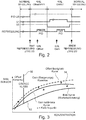
- FIG. 2 clarifies the time course of the measuring process described above.
- FIG. 3 illustrates the calculation for the compensation of the cross-sensitivity of the first sensor 22 based on the measurement results of the second sensor 24th
- a class boundary 52 divides the curve into an offset correction region and a gain correction region.
- other algorithms are also possible to modify offset and gain or even the exponential characteristic.
- the current measured value of the second sensor is used as a reference variable for a statistical probability calculation of all previously determined calibration points or measured values. The most unlikely measured values are then removed from the collection of the measured values, and with the average of the other measured values that are more probable, a new slope and thus a corrected curve 54 relative to a basic characteristic 53 are determined and the system slope is slowly tracked via a filter.
Landscapes
- Chemical & Material Sciences (AREA)
- Health & Medical Sciences (AREA)
- Life Sciences & Earth Sciences (AREA)
- Engineering & Computer Science (AREA)
- General Physics & Mathematics (AREA)
- Pathology (AREA)
- Immunology (AREA)
- Physics & Mathematics (AREA)
- Analytical Chemistry (AREA)
- Biochemistry (AREA)
- General Health & Medical Sciences (AREA)
- Food Science & Technology (AREA)
- Medicinal Chemistry (AREA)
- Combustion & Propulsion (AREA)
- Investigating Or Analyzing Materials By The Use Of Electric Means (AREA)
- Chemical Kinetics & Catalysis (AREA)
- Electrochemistry (AREA)
- Other Investigation Or Analysis Of Materials By Electrical Means (AREA)
- Molecular Biology (AREA)
- Investigating Or Analyzing Materials By The Use Of Fluid Adsorption Or Reactions (AREA)
- Toxicology (AREA)
Claims (15)
- Instrument de mesure (20) pour capturer les taux d'hydrocarbures dans les gazes, comprenant- un premier capteur (22) pour déterminer le taux d'hydrocarbures dans un premier courant de gaz de mesure (38) et pour produire un premier résultat de mesure approprié, un second capteur (24) pour déterminer le taux d'hydrocarbures dans un second courant de gaz de mesure (39) et pour produire un second résultat de mesure approprié,- une unité d'analyse pour analyser les résultats de mesure des deux capteurs (22, 24), une unité de catalyseur (34) pour produire un courant de gaz catalyseur (36)dans lequel- le premier capteur (22) et configuré comme capteur de gaz à oxyde métallique semi-conducteur réalisant des mesures continues,- le deuxième capteur (24) est configuré comme capteur photoionisation réalisant des mesures discontinues,- le courant de gaz catalyseur (36) est conductible vers le second capteur (24).
- Instrument de mesure (20) selon la revendication 1, caractérisé par le fait, qu'une seconde unité de catalyseur (30) pour produire un second courant de gaz catalyseur (32) est présente, qui est conductible vers le premier capteur (22).
- Instrument de mesure (20) selon l'une des revendications 1 à 2, caractérisé par le fait, que les unités de catalyseur (30, 34) sont formées par des catalyseurs d'oxydation.
- Instrument de mesure (20) selon l'une des revendications 1 à 3, caractérisé par le fait, qu'un courant de gaz de référence (SO) ayant une concentration des hydrocarbures dans la plage de mesure élevée de deux capteurs (22, 24) est conductible vers les deux capteurs (22. 24).
- Instrument de mesure (20) selon l'une des revendications 1 à 4, caractérisé par le fait, qu'un élément de filtrage (40) pour le filtrage du courant de gaz de mesure (26) est présent dans la direction du flux en aval des capteurs (22, 24).
- Instrument de mesure (20) selon l'une des revendications 1 à 5, caractérisé par le fait, qu'un élément de séchage (42) pour le séchage des courants de gaz de mesure (38, 39) est présent dans la direction du flux en aval des capteurs (22, 24).
- Instrument de mesure (20) selon l'une de revendication 5, caractérisé par le fait, que l'élément de séchage (42) est ménagé en tant que sécheur à membrane.
- Procédé pour capturer le taux d'hydrocarbures dans un courant de gaz, caractérisé par les étapes du processus consistant à- conduire, de manière continue, un premier courant de gaz de mesures (38) vers un premier capteur (22), qui est configuré comme capteur de gaz à oxyde métallique semi-conducteur,- déterminer le taux d'hydrocarbure dans le premier courant de gaz de mesure (38) et produire un premier résultat de mesure par le premier capteur (22),- conduire, de manière discontinue, un second courant de gaz de mesure (39) vers un second capteur (24), qui est configuré comme capteur photoionisation,- déterminer le taux d'hydrocarbure dans le second courant de gaz de mesure (39) et produire un second résultat de mesure par le second capteur (24),- analyser le résultat de mesure des deux capteurs (22, 24),- produire un courant de gaz de catalyseur (36), dans lequel le courant de gaz catalyseur (36) est conduit au second capteur (24) lorsque le deuxième capteur (24) est arrêté ou n'est pas utilisé.
- Procédé selon la revendication 8, caractérisé par le fait, que- le deuxième capteur (24) ne sera activé que immédiatement avant l'emploi,- après un temps de stabilisation suffisant un réglage du zéro automatique est mise en oeuvre,- après le réglage du zéro, le courant de gaz de mesure (39) y est conduit.
- Procédé selon l'une des revendications 8 bis 9, caractérisé par le fait, que, à la suite de la mesure parallèle des deux capteurs (22, 24), les résultats de mesure des deux capteurs (22, 24) seront comparés et, le cas nécessaire, le premier capteur (22) sera calibré.
- Procédé selon l'une des revendications 8 bis 10, caractérisé par le fait, que les courants de gaz de mesure (38, 39), avant les conduire vers les deux capteurs (22,24), sont filtrés à l'aide d'un élément de filtrage (40).
- Procédé selon l'une des revendications 8 bis 11 caractérisé par le fait, que les courants de gaz de mesure (38, 39), avant les conduire vers les deux capteurs (22,24), sont séchés à l'aide d'un élément de séchage (42).
- Procédé selon l'une des revendications 8 bis 12, caractérisé par un calibrage des deux capteurs (22, 24) à l'aide d'un courant de gaz de référence (50) ayant une concentration d'hydrocarbures dans la plage de mesure élevée des deux capteurs (22,24).
- Procédé selon l'une des revendications 8 bis 13, caractérisé par la compensation d'une sensibilité croisée du premier capteur (22), lorsque les valeurs mesurées du second capteur (24) sont plus mauvaises que classe 1 (selon ISO 8573), par le fait dea. utiliser un résultat de mesure actuel du second capteur (24) comme grandeur de contrôle pour un calcul des probabilités statistique des valeurs de calibrage du premier capteur (22) déterminées auparavant,b. éliminer les valeurs de calibrage les plus improbables de la collection des valeurs de calibrage antérieures,c. déterminer une pente d'une courbe de mesure à partir d'une valeur moyenne résultant de la collection des valeurs antérieures après l'élimination des valeurs de calibrage les plus improbables,d. tracer une pente de système à l'aide d'un filtre.
- Procédé selon l'une des revendications 8 bis 14, caractérisé par une correction d'une valeur de décalage du premier capteur (22), lorsque les valeurs de mesure du second capteur (24) sont meilleures que classe 1 (selon ISO 8573), par le fait dea. déterminer un point de travail sur une courbe de mesure à partir des résultats de mesure du premier capteur (22)b. calculer de valeurs pour la correction de la valeur de décalage du premier capteur (22).c. tenir compte de la courbe caractéristique exponentielle du premier capteur (22) lors de la détermination de la valeur de décalage.
Applications Claiming Priority (2)
| Application Number | Priority Date | Filing Date | Title |
|---|---|---|---|
| DE102013100950.6A DE102013100950A1 (de) | 2013-01-30 | 2013-01-30 | Messgerät und Verfahren zum Erfassen des Kohlenwasserstoffanteils in Gasen |
| PCT/EP2014/051041 WO2014118028A1 (fr) | 2013-01-30 | 2014-01-20 | Appareil de mesure de restes d'huile |
Publications (2)
| Publication Number | Publication Date |
|---|---|
| EP2951573A1 EP2951573A1 (fr) | 2015-12-09 |
| EP2951573B1 true EP2951573B1 (fr) | 2017-11-29 |
Family
ID=49998298
Family Applications (1)
| Application Number | Title | Priority Date | Filing Date |
|---|---|---|---|
| EP14700928.6A Not-in-force EP2951573B1 (fr) | 2013-01-30 | 2014-01-20 | Appareil de mesure de restes d'huile |
Country Status (8)
| Country | Link |
|---|---|
| US (1) | US20150369784A1 (fr) |
| EP (1) | EP2951573B1 (fr) |
| JP (1) | JP2016509219A (fr) |
| KR (1) | KR20150112034A (fr) |
| CN (1) | CN104956221A (fr) |
| BR (1) | BR112015016810A2 (fr) |
| DE (1) | DE102013100950A1 (fr) |
| WO (1) | WO2014118028A1 (fr) |
Families Citing this family (12)
| Publication number | Priority date | Publication date | Assignee | Title |
|---|---|---|---|---|
| DE102015219838A1 (de) * | 2015-10-13 | 2017-04-13 | bentekk GmbH | Kontinuierliche und trennende Gasanalyse |
| US10101298B1 (en) * | 2017-04-18 | 2018-10-16 | Broadsens Corp. | Photo ionization detector with self-calibration |
| DE102017108609A1 (de) * | 2017-04-21 | 2018-10-25 | Beko Technologies Gmbh | Kompaktes Messgerät und Verfahren zum Erfassen von Kohlenwasserstoffen |
| DE102017110056B4 (de) * | 2017-05-10 | 2019-02-21 | Beko Technologies Gmbh | Öldampfmessgerät mit Referenzgasgenerator |
| NL2022204B1 (nl) * | 2018-12-13 | 2020-07-03 | Green Vision Holding Bv | Werkwijze en inrichting voor het bepalen van de concentratie van een gasvormige verontreiniging in een productgas van zeer hoge zuiverheid |
| US11585797B2 (en) * | 2019-06-28 | 2023-02-21 | Li-Cor, Inc. | Dynamic and real-time correction of differential measurement offsets in a gas analysis system |
| CN110208359A (zh) * | 2019-07-04 | 2019-09-06 | 希尔思仪表(深圳)有限公司 | 用于测量气体中油蒸汽或其它烃类含量的测量装置及测量方法 |
| GB2593511A (en) * | 2020-03-25 | 2021-09-29 | Sumitomo Chemical Co | Sensor apparatus |
| FR3112206B1 (fr) | 2020-07-01 | 2023-02-10 | Rubix S&I | Système de captation chimique à étalonnage intégré et procédé d’utilisation d’un tel système |
| CN114405263A (zh) * | 2021-12-24 | 2022-04-29 | 宁波鲍斯能源装备股份有限公司 | 一种催化除油设备的保护装置及催化无油压缩系统 |
| US20250155403A1 (en) * | 2023-11-15 | 2025-05-15 | Uop Llc | Systems and process for calibrating a sensor used in a sulfur extraction process |
| DE102024202191B3 (de) | 2024-03-08 | 2025-05-15 | Schaeffler Technologies AG & Co. KG | Verfahren, Steuerungsvorrichtung, Batterievorrichtungsdiagnosevorrichtung und Computerprogramm zum Ermitteln eines thermischen Durchgehens einer Batterieanordnung sowie Batterievorrichtung und Fahrzeug |
Family Cites Families (8)
| Publication number | Priority date | Publication date | Assignee | Title |
|---|---|---|---|---|
| DE2626905C2 (de) * | 1976-06-16 | 1984-08-30 | Hartmann & Braun Ag, 6000 Frankfurt | Anordnung zur Messung des methanfreien Anteils an Kohlenwasserstoffen in einem Gasgemisch |
| JPH1166465A (ja) * | 1997-08-26 | 1999-03-09 | New Cosmos Electric Corp | ガス漏れ警報器 |
| JP3830778B2 (ja) * | 2001-06-19 | 2006-10-11 | 三菱電機株式会社 | 臭気管理装置および臭気管理方法 |
| EP2252883B1 (fr) * | 2008-03-10 | 2014-04-02 | AIRSENSE Analytics GmbH | Procédé de détection et d'identification de gaz dans les espaces intérieurs d'aéronef |
| DE102008028682A1 (de) * | 2008-06-17 | 2010-02-25 | Airbus Deutschland Gmbh | Verfahren zum Vermessen von Gaskonzentrationen mittels eines Metalloxid-Gassensors, Sensorvorrichtung zum Durchführen des Verfahrens sowie Verwendung desselben |
| DE102009004278A1 (de) * | 2009-01-05 | 2010-07-15 | Synthesechemie Dr. Penth Gmbh | Messgerät für geringe Kohlenwasserstoffkonzentrationen |
| US9128061B2 (en) * | 2009-02-18 | 2015-09-08 | Beko Technologies Gmbh | Measuring device and method for detecting the hydrocarbon content in gases |
| DE102010020110A1 (de) * | 2010-05-10 | 2012-11-22 | Synthesechemie Gmbh | Gerät zum Erfassen und Verdünnen für geringe Kohlenwasserstoffkonzentrationen in Druckluft |
-
2013
- 2013-01-30 DE DE102013100950.6A patent/DE102013100950A1/de not_active Withdrawn
-
2014
- 2014-01-20 KR KR1020157023703A patent/KR20150112034A/ko not_active Withdrawn
- 2014-01-20 JP JP2015555638A patent/JP2016509219A/ja active Pending
- 2014-01-20 US US14/764,844 patent/US20150369784A1/en not_active Abandoned
- 2014-01-20 CN CN201480006829.0A patent/CN104956221A/zh active Pending
- 2014-01-20 BR BR112015016810A patent/BR112015016810A2/pt not_active IP Right Cessation
- 2014-01-20 WO PCT/EP2014/051041 patent/WO2014118028A1/fr not_active Ceased
- 2014-01-20 EP EP14700928.6A patent/EP2951573B1/fr not_active Not-in-force
Also Published As
| Publication number | Publication date |
|---|---|
| KR20150112034A (ko) | 2015-10-06 |
| BR112015016810A2 (pt) | 2017-07-11 |
| EP2951573A1 (fr) | 2015-12-09 |
| DE102013100950A1 (de) | 2014-07-31 |
| US20150369784A1 (en) | 2015-12-24 |
| CN104956221A (zh) | 2015-09-30 |
| WO2014118028A1 (fr) | 2014-08-07 |
| JP2016509219A (ja) | 2016-03-24 |
Similar Documents
| Publication | Publication Date | Title |
|---|---|---|
| EP2951573B1 (fr) | Appareil de mesure de restes d'huile | |
| EP2773951B1 (fr) | Appareil de mesure et procédé permettant de détecter la proportion d'hydrocarbures dans des gaz | |
| EP2399124B1 (fr) | Procédé de détection de la teneur en hydrocarbures de gaz | |
| EP2373991B1 (fr) | Appareil de mesure et procédé pour détecter la teneur en huile, hydrocarbures et gaz oxydables dans l'air ou l'air comprimé | |
| EP1058846B1 (fr) | Procede et dispositif pour identifier des composes gazeux | |
| EP2825879B1 (fr) | Contrôle du fonctionnement de capteurs de gaz de conductivité thermique | |
| EP2856146A1 (fr) | Appareil de mesure et procédé pour appréhender la proportion d'hydrocarbures dans des gaz et tenant compte de la sensibilité aux influences parasites | |
| EP2629082B1 (fr) | Dispositif de détection d'une pression partielle et procédé de fonctionnement de celui-ci | |
| EP3612833B1 (fr) | Appareil de mesure compact et procédé pour la detection d'hydrocarbures | |
| EP3452818A1 (fr) | Procédé permettant de faire fonctionner une sonde | |
| EP3847456B1 (fr) | Analyse d'un gaz dissous dans un milieu isolant d'un appareil à haute tension | |
| DE102010020110A1 (de) | Gerät zum Erfassen und Verdünnen für geringe Kohlenwasserstoffkonzentrationen in Druckluft | |
| DE10316332A1 (de) | Verfahren und Vorrichtung zur Dichtheitsprüfung | |
| WO2024028217A1 (fr) | Procédé et capteur de gaz pour déterminer la concentration d'un composant gazeux dans un mélange gazeux | |
| DE102011005694A1 (de) | Verfahren zur in-situ-Kalibrierung eines Sensorelements | |
| DE102019212309A1 (de) | Gasanalysevorrichtung | |
| DE102005031552B4 (de) | Verfahren zur Betriebsprüfung einer Messeinrichtung | |
| WO2018206423A1 (fr) | Appareil de mesue de vapeur d'huile avec générateur de gaz de référence | |
| EP3527966B1 (fr) | Procédé et dispositif de détermination d'une indication de fuite d'un objet d'essai rempli de fluide d'essai | |
| DE202023105080U1 (de) | Vorrichtung zur Bestimmung einer Eigenschaft eines Messgases | |
| EP0955541A2 (fr) | Procédé et cellule de mesure pour mesurer la teneur d'humidité dans des gaz | |
| AT413888B (de) | Konzentrationsmonitor für fluidproben | |
| DE202012009711U1 (de) | Vorrichtung zur qualitativen und quantitativen Analyse der Komponenten eines Gases | |
| DE102019210208A1 (de) | Flammenionisationsdetektor und Verfahren zur Analyse eines sauerstoffhaltigen Messgases | |
| DE102016014068A1 (de) | Verfahren zur Funktionsüberprüfung eines Gassensors |
Legal Events
| Date | Code | Title | Description |
|---|---|---|---|
| PUAI | Public reference made under article 153(3) epc to a published international application that has entered the european phase |
Free format text: ORIGINAL CODE: 0009012 |
|
| 17P | Request for examination filed |
Effective date: 20150727 |
|
| AK | Designated contracting states |
Kind code of ref document: A1 Designated state(s): AL AT BE BG CH CY CZ DE DK EE ES FI FR GB GR HR HU IE IS IT LI LT LU LV MC MK MT NL NO PL PT RO RS SE SI SK SM TR |
|
| AX | Request for extension of the european patent |
Extension state: BA ME |
|
| DAX | Request for extension of the european patent (deleted) | ||
| GRAP | Despatch of communication of intention to grant a patent |
Free format text: ORIGINAL CODE: EPIDOSNIGR1 |
|
| INTG | Intention to grant announced |
Effective date: 20160923 |
|
| GRAS | Grant fee paid |
Free format text: ORIGINAL CODE: EPIDOSNIGR3 |
|
| GRAA | (expected) grant |
Free format text: ORIGINAL CODE: 0009210 |
|
| AK | Designated contracting states |
Kind code of ref document: B1 Designated state(s): AL AT BE BG CH CY CZ DE DK EE ES FI FR GB GR HR HU IE IS IT LI LT LU LV MC MK MT NL NO PL PT RO RS SE SI SK SM TR |
|
| RAP1 | Party data changed (applicant data changed or rights of an application transferred) |
Owner name: FRIEDRICH, MARTIN |
|
| RIN1 | Information on inventor provided before grant (corrected) |
Inventor name: FRIEDRICH, MARTIN |
|
| REG | Reference to a national code |
Ref country code: CH Ref legal event code: EP |
|
| REG | Reference to a national code |
Ref country code: AT Ref legal event code: REF Ref document number: 950857 Country of ref document: AT Kind code of ref document: T Effective date: 20171215 |
|
| REG | Reference to a national code |
Ref country code: IE Ref legal event code: FG4D Free format text: LANGUAGE OF EP DOCUMENT: GERMAN |
|
| REG | Reference to a national code |
Ref country code: DE Ref legal event code: R096 Ref document number: 502014006395 Country of ref document: DE |
|
| REG | Reference to a national code |
Ref country code: FR Ref legal event code: PLFP Year of fee payment: 5 |
|
| REG | Reference to a national code |
Ref country code: NL Ref legal event code: MP Effective date: 20171129 |
|
| REG | Reference to a national code |
Ref country code: LT Ref legal event code: MG4D |
|
| PG25 | Lapsed in a contracting state [announced via postgrant information from national office to epo] |
Ref country code: SE Free format text: LAPSE BECAUSE OF FAILURE TO SUBMIT A TRANSLATION OF THE DESCRIPTION OR TO PAY THE FEE WITHIN THE PRESCRIBED TIME-LIMIT Effective date: 20171129 Ref country code: FI Free format text: LAPSE BECAUSE OF FAILURE TO SUBMIT A TRANSLATION OF THE DESCRIPTION OR TO PAY THE FEE WITHIN THE PRESCRIBED TIME-LIMIT Effective date: 20171129 Ref country code: ES Free format text: LAPSE BECAUSE OF FAILURE TO SUBMIT A TRANSLATION OF THE DESCRIPTION OR TO PAY THE FEE WITHIN THE PRESCRIBED TIME-LIMIT Effective date: 20171129 Ref country code: LT Free format text: LAPSE BECAUSE OF FAILURE TO SUBMIT A TRANSLATION OF THE DESCRIPTION OR TO PAY THE FEE WITHIN THE PRESCRIBED TIME-LIMIT Effective date: 20171129 Ref country code: NO Free format text: LAPSE BECAUSE OF FAILURE TO SUBMIT A TRANSLATION OF THE DESCRIPTION OR TO PAY THE FEE WITHIN THE PRESCRIBED TIME-LIMIT Effective date: 20180228 |
|
| PG25 | Lapsed in a contracting state [announced via postgrant information from national office to epo] |
Ref country code: BG Free format text: LAPSE BECAUSE OF FAILURE TO SUBMIT A TRANSLATION OF THE DESCRIPTION OR TO PAY THE FEE WITHIN THE PRESCRIBED TIME-LIMIT Effective date: 20180228 Ref country code: HR Free format text: LAPSE BECAUSE OF FAILURE TO SUBMIT A TRANSLATION OF THE DESCRIPTION OR TO PAY THE FEE WITHIN THE PRESCRIBED TIME-LIMIT Effective date: 20171129 Ref country code: LV Free format text: LAPSE BECAUSE OF FAILURE TO SUBMIT A TRANSLATION OF THE DESCRIPTION OR TO PAY THE FEE WITHIN THE PRESCRIBED TIME-LIMIT Effective date: 20171129 Ref country code: RS Free format text: LAPSE BECAUSE OF FAILURE TO SUBMIT A TRANSLATION OF THE DESCRIPTION OR TO PAY THE FEE WITHIN THE PRESCRIBED TIME-LIMIT Effective date: 20171129 Ref country code: GR Free format text: LAPSE BECAUSE OF FAILURE TO SUBMIT A TRANSLATION OF THE DESCRIPTION OR TO PAY THE FEE WITHIN THE PRESCRIBED TIME-LIMIT Effective date: 20180301 |
|
| PG25 | Lapsed in a contracting state [announced via postgrant information from national office to epo] |
Ref country code: NL Free format text: LAPSE BECAUSE OF FAILURE TO SUBMIT A TRANSLATION OF THE DESCRIPTION OR TO PAY THE FEE WITHIN THE PRESCRIBED TIME-LIMIT Effective date: 20171129 |
|
| PG25 | Lapsed in a contracting state [announced via postgrant information from national office to epo] |
Ref country code: DK Free format text: LAPSE BECAUSE OF FAILURE TO SUBMIT A TRANSLATION OF THE DESCRIPTION OR TO PAY THE FEE WITHIN THE PRESCRIBED TIME-LIMIT Effective date: 20171129 Ref country code: SK Free format text: LAPSE BECAUSE OF FAILURE TO SUBMIT A TRANSLATION OF THE DESCRIPTION OR TO PAY THE FEE WITHIN THE PRESCRIBED TIME-LIMIT Effective date: 20171129 Ref country code: CZ Free format text: LAPSE BECAUSE OF FAILURE TO SUBMIT A TRANSLATION OF THE DESCRIPTION OR TO PAY THE FEE WITHIN THE PRESCRIBED TIME-LIMIT Effective date: 20171129 Ref country code: EE Free format text: LAPSE BECAUSE OF FAILURE TO SUBMIT A TRANSLATION OF THE DESCRIPTION OR TO PAY THE FEE WITHIN THE PRESCRIBED TIME-LIMIT Effective date: 20171129 Ref country code: CY Free format text: LAPSE BECAUSE OF FAILURE TO SUBMIT A TRANSLATION OF THE DESCRIPTION OR TO PAY THE FEE WITHIN THE PRESCRIBED TIME-LIMIT Effective date: 20171129 |
|
| REG | Reference to a national code |
Ref country code: DE Ref legal event code: R097 Ref document number: 502014006395 Country of ref document: DE |
|
| PG25 | Lapsed in a contracting state [announced via postgrant information from national office to epo] |
Ref country code: SM Free format text: LAPSE BECAUSE OF FAILURE TO SUBMIT A TRANSLATION OF THE DESCRIPTION OR TO PAY THE FEE WITHIN THE PRESCRIBED TIME-LIMIT Effective date: 20171129 Ref country code: PL Free format text: LAPSE BECAUSE OF FAILURE TO SUBMIT A TRANSLATION OF THE DESCRIPTION OR TO PAY THE FEE WITHIN THE PRESCRIBED TIME-LIMIT Effective date: 20171129 Ref country code: RO Free format text: LAPSE BECAUSE OF FAILURE TO SUBMIT A TRANSLATION OF THE DESCRIPTION OR TO PAY THE FEE WITHIN THE PRESCRIBED TIME-LIMIT Effective date: 20171129 Ref country code: IT Free format text: LAPSE BECAUSE OF FAILURE TO SUBMIT A TRANSLATION OF THE DESCRIPTION OR TO PAY THE FEE WITHIN THE PRESCRIBED TIME-LIMIT Effective date: 20171129 |
|
| PG25 | Lapsed in a contracting state [announced via postgrant information from national office to epo] |
Ref country code: MT Free format text: LAPSE BECAUSE OF FAILURE TO SUBMIT A TRANSLATION OF THE DESCRIPTION OR TO PAY THE FEE WITHIN THE PRESCRIBED TIME-LIMIT Effective date: 20171129 |
|
| PLBE | No opposition filed within time limit |
Free format text: ORIGINAL CODE: 0009261 |
|
| STAA | Information on the status of an ep patent application or granted ep patent |
Free format text: STATUS: NO OPPOSITION FILED WITHIN TIME LIMIT |
|
| PG25 | Lapsed in a contracting state [announced via postgrant information from national office to epo] |
Ref country code: LU Free format text: LAPSE BECAUSE OF NON-PAYMENT OF DUE FEES Effective date: 20180120 |
|
| REG | Reference to a national code |
Ref country code: IE Ref legal event code: MM4A |
|
| 26N | No opposition filed |
Effective date: 20180830 |
|
| REG | Reference to a national code |
Ref country code: BE Ref legal event code: MM Effective date: 20180131 |
|
| PG25 | Lapsed in a contracting state [announced via postgrant information from national office to epo] |
Ref country code: SI Free format text: LAPSE BECAUSE OF FAILURE TO SUBMIT A TRANSLATION OF THE DESCRIPTION OR TO PAY THE FEE WITHIN THE PRESCRIBED TIME-LIMIT Effective date: 20171129 Ref country code: BE Free format text: LAPSE BECAUSE OF NON-PAYMENT OF DUE FEES Effective date: 20180131 |
|
| PG25 | Lapsed in a contracting state [announced via postgrant information from national office to epo] |
Ref country code: IE Free format text: LAPSE BECAUSE OF NON-PAYMENT OF DUE FEES Effective date: 20180120 |
|
| PGFP | Annual fee paid to national office [announced via postgrant information from national office to epo] |
Ref country code: FR Payment date: 20190130 Year of fee payment: 6 Ref country code: GB Payment date: 20190221 Year of fee payment: 6 Ref country code: DE Payment date: 20190219 Year of fee payment: 6 Ref country code: CH Payment date: 20190221 Year of fee payment: 6 |
|
| PG25 | Lapsed in a contracting state [announced via postgrant information from national office to epo] |
Ref country code: MC Free format text: LAPSE BECAUSE OF FAILURE TO SUBMIT A TRANSLATION OF THE DESCRIPTION OR TO PAY THE FEE WITHIN THE PRESCRIBED TIME-LIMIT Effective date: 20171129 |
|
| REG | Reference to a national code |
Ref country code: AT Ref legal event code: MM01 Ref document number: 950857 Country of ref document: AT Kind code of ref document: T Effective date: 20190120 |
|
| PG25 | Lapsed in a contracting state [announced via postgrant information from national office to epo] |
Ref country code: TR Free format text: LAPSE BECAUSE OF FAILURE TO SUBMIT A TRANSLATION OF THE DESCRIPTION OR TO PAY THE FEE WITHIN THE PRESCRIBED TIME-LIMIT Effective date: 20171129 |
|
| PG25 | Lapsed in a contracting state [announced via postgrant information from national office to epo] |
Ref country code: AT Free format text: LAPSE BECAUSE OF NON-PAYMENT OF DUE FEES Effective date: 20190120 |
|
| PG25 | Lapsed in a contracting state [announced via postgrant information from national office to epo] |
Ref country code: PT Free format text: LAPSE BECAUSE OF FAILURE TO SUBMIT A TRANSLATION OF THE DESCRIPTION OR TO PAY THE FEE WITHIN THE PRESCRIBED TIME-LIMIT Effective date: 20171129 |
|
| PG25 | Lapsed in a contracting state [announced via postgrant information from national office to epo] |
Ref country code: HU Free format text: LAPSE BECAUSE OF FAILURE TO SUBMIT A TRANSLATION OF THE DESCRIPTION OR TO PAY THE FEE WITHIN THE PRESCRIBED TIME-LIMIT; INVALID AB INITIO Effective date: 20140120 Ref country code: MK Free format text: LAPSE BECAUSE OF NON-PAYMENT OF DUE FEES Effective date: 20171129 |
|
| PG25 | Lapsed in a contracting state [announced via postgrant information from national office to epo] |
Ref country code: AL Free format text: LAPSE BECAUSE OF FAILURE TO SUBMIT A TRANSLATION OF THE DESCRIPTION OR TO PAY THE FEE WITHIN THE PRESCRIBED TIME-LIMIT Effective date: 20171129 Ref country code: IS Free format text: LAPSE BECAUSE OF FAILURE TO SUBMIT A TRANSLATION OF THE DESCRIPTION OR TO PAY THE FEE WITHIN THE PRESCRIBED TIME-LIMIT Effective date: 20180329 |
|
| REG | Reference to a national code |
Ref country code: DE Ref legal event code: R119 Ref document number: 502014006395 Country of ref document: DE |
|
| REG | Reference to a national code |
Ref country code: CH Ref legal event code: PL |
|
| GBPC | Gb: european patent ceased through non-payment of renewal fee |
Effective date: 20200120 |
|
| PG25 | Lapsed in a contracting state [announced via postgrant information from national office to epo] |
Ref country code: DE Free format text: LAPSE BECAUSE OF NON-PAYMENT OF DUE FEES Effective date: 20200801 Ref country code: FR Free format text: LAPSE BECAUSE OF NON-PAYMENT OF DUE FEES Effective date: 20200131 Ref country code: GB Free format text: LAPSE BECAUSE OF NON-PAYMENT OF DUE FEES Effective date: 20200120 |
|
| PG25 | Lapsed in a contracting state [announced via postgrant information from national office to epo] |
Ref country code: CH Free format text: LAPSE BECAUSE OF NON-PAYMENT OF DUE FEES Effective date: 20200131 Ref country code: LI Free format text: LAPSE BECAUSE OF NON-PAYMENT OF DUE FEES Effective date: 20200131 |