EP2951596B1 - Module d'alimentation en énergie et procédé pour faire fonctionner un module d'alimentation en énergie afin d'alimenter une charge de manière autonome - Google Patents
Module d'alimentation en énergie et procédé pour faire fonctionner un module d'alimentation en énergie afin d'alimenter une charge de manière autonome Download PDFInfo
- Publication number
- EP2951596B1 EP2951596B1 EP13802406.2A EP13802406A EP2951596B1 EP 2951596 B1 EP2951596 B1 EP 2951596B1 EP 13802406 A EP13802406 A EP 13802406A EP 2951596 B1 EP2951596 B1 EP 2951596B1
- Authority
- EP
- European Patent Office
- Prior art keywords
- reset
- unit
- energy supply
- monitoring
- uin
- Prior art date
- Legal status (The legal status is an assumption and is not a legal conclusion. Google has not performed a legal analysis and makes no representation as to the accuracy of the status listed.)
- Active
Links
Images



Classifications
-
- B—PERFORMING OPERATIONS; TRANSPORTING
- B60—VEHICLES IN GENERAL
- B60R—VEHICLES, VEHICLE FITTINGS, OR VEHICLE PARTS, NOT OTHERWISE PROVIDED FOR
- B60R21/00—Arrangements or fittings on vehicles for protecting or preventing injuries to occupants or pedestrians in case of accidents or other traffic risks
- B60R21/01—Electrical circuits for triggering passive safety arrangements, e.g. airbags, safety belt tighteners, in case of vehicle accidents or impending vehicle accidents
- B60R21/017—Electrical circuits for triggering passive safety arrangements, e.g. airbags, safety belt tighteners, in case of vehicle accidents or impending vehicle accidents including arrangements for providing electric power to safety arrangements or their actuating means, e.g. to pyrotechnic fuses or electro-mechanic valves
- B60R21/0173—Diagnostic or recording means therefor
-
- G—PHYSICS
- G01—MEASURING; TESTING
- G01R—MEASURING ELECTRIC VARIABLES; MEASURING MAGNETIC VARIABLES
- G01R19/00—Arrangements for measuring currents or voltages or for indicating presence or sign thereof
- G01R19/165—Indicating that current or voltage is either above or below a predetermined value or within or outside a predetermined range of values
- G01R19/16533—Indicating that current or voltage is either above or below a predetermined value or within or outside a predetermined range of values characterised by the application
- G01R19/16538—Indicating that current or voltage is either above or below a predetermined value or within or outside a predetermined range of values characterised by the application in AC or DC supplies
- G01R19/16542—Indicating that current or voltage is either above or below a predetermined value or within or outside a predetermined range of values characterised by the application in AC or DC supplies for batteries
-
- H—ELECTRICITY
- H02—GENERATION; CONVERSION OR DISTRIBUTION OF ELECTRIC POWER
- H02J—ELECTRIC POWER NETWORKS; CIRCUIT ARRANGEMENTS OR SYSTEMS FOR SUPPLYING OR DISTRIBUTING ELECTRIC POWER; SYSTEMS FOR STORING ELECTRIC ENERGY
- H02J9/00—Circuit arrangements for emergency or stand-by power supply, e.g. for emergency lighting
- H02J9/04—Circuit arrangements for emergency or stand-by power supply, e.g. for emergency lighting in which the distribution system is disconnected from the normal source and connected to a standby source
- H02J9/06—Circuit arrangements for emergency or stand-by power supply, e.g. for emergency lighting in which the distribution system is disconnected from the normal source and connected to a standby source with automatic change-over, e.g. UPS systems
- H02J9/061—Circuit arrangements for emergency or stand-by power supply, e.g. for emergency lighting in which the distribution system is disconnected from the normal source and connected to a standby source with automatic change-over, e.g. UPS systems for DC powered loads
-
- G—PHYSICS
- G01—MEASURING; TESTING
- G01R—MEASURING ELECTRIC VARIABLES; MEASURING MAGNETIC VARIABLES
- G01R19/00—Arrangements for measuring currents or voltages or for indicating presence or sign thereof
- G01R19/165—Indicating that current or voltage is either above or below a predetermined value or within or outside a predetermined range of values
- G01R19/16533—Indicating that current or voltage is either above or below a predetermined value or within or outside a predetermined range of values characterised by the application
- G01R19/16538—Indicating that current or voltage is either above or below a predetermined value or within or outside a predetermined range of values characterised by the application in AC or DC supplies
Definitions
- time requirements for the RESET signal are also implemented. If the conditions for a transition from the RESET "active" state to a RESET “inactive” state occur, this only becomes effective in the RESET signal after a delay time. A “short” filter time can also make sense for the reverse transition.
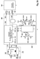
- a regulated voltage Uout (related to the reference potential 120) is output at an output current IL, which represents a total current that can be made available to a sum of consumers 140 by the voltage regulator 100.
- the consumers 140 can all be controlled by a RESET signal that is output as a monitoring signal 150 by the voltage regulator 100.
- the terms monitoring signal, RESET, RESET signal and RESET state are used, whereby these terms are to be understood as a signal or as the value of the monitoring signal depending on the context.
- this voltage increase is Ri x (IL_on - IL_off); for the above example, the voltage increase amount is 0.5V.
- the increase is limited by the regulator to the control voltage Uout_reg.
- a signal that can be tapped at the output of the further AND gate 340 is then delayed by a time period Tf2 using a third delay unit 350 when the level at the output of the third AND gate 350 changes from a value of logic 1 to logic 0, and the signal at the output of the third AND gate 350 is not delayed when the level at the output of the third AND gate 350 changes from a value of logic 0 to logic 1.
- the signal output by the third delay unit 350 can then be understood as a monitoring signal RESET, which is amplified by the driver 235 and delivered to corresponding consumers 140.
- Fig.5 shows a flow chart of an embodiment of the present invention as a method 500 for operating a power supply unit according to a variant presented above for the autonomous supply of a consumer.
- the method 500 comprises a step 510 of setting the monitoring signal to an active state when an output voltage applied between the output and a reference potential is less than a predefined activation threshold.
- the method 500 further comprises a step 520 of bringing the monitoring signal to an inactive state when an input voltage applied between the input and the reference potential has risen again above a reset threshold.
Landscapes
- Engineering & Computer Science (AREA)
- Power Engineering (AREA)
- Mechanical Engineering (AREA)
- Physics & Mathematics (AREA)
- General Physics & Mathematics (AREA)
- Business, Economics & Management (AREA)
- Emergency Management (AREA)
- Dc-Dc Converters (AREA)
- Measurement Of Current Or Voltage (AREA)
- Direct Current Feeding And Distribution (AREA)
- Electronic Switches (AREA)
- Control Of Voltage And Current In General (AREA)
Claims (13)
- Unité d'alimentation en énergie (200) pour l'alimentation autonome d'un consommateur (140), l'unité d'alimentation en énergie (200) présentant les particularités suivantes :- un accumulateur d'énergie (ER) qui est réalisé pour fournir de l'énergie électrique à un consommateur (140) lorsque le consommateur électrique (140) est découplé d'un réseau d'alimentation en énergie (115) ;- une unité de régulation d'alimentation en énergie (100) pourvue d'une entrée (110) couplée à l'accumulateur d'énergie (ER) pour recevoir de l'énergie électrique, et pourvue d'une sortie (130) pour délivrer de l'énergie électrique au consommateur (140) ; l'unité d'alimentation en énergie étant caractérisée en ce qu'elle présente en outre :- une unité de surveillance (230) pour émettre un signal de surveillance (150, RESET), l'unité de surveillance (230) étant réalisée pour régler le signal de surveillance (150, RESET) sur un état actif (« 0 ») lorsqu'une tension de sortie (Uout) appliquée entre la sortie (130) et un potentiel de référence (120) est inférieure à une première valeur seuil d'activation (Uout_ru) prédéfinie ou supérieure à une deuxième valeur seuil d'activation (Uout_ro) prédéfinie, dans laquelle l'unité de surveillance (230) est en outre réalisée pour réinitialiser le signal de surveillance (150, RESET) sur un état inactif (« 1 ») lorsqu'une tension d'entrée (Uin) appliquée entre l'entrée (110) et le potentiel de référence (120) remonte ou se situe à nouveau au-dessus d'une valeur seuil de réinitialisation (Uin_min).
- Unité d'alimentation en énergie (200) selon la revendication 1, caractérisée en ce que l'unité de surveillance (230) est réalisée pour maintenir le signal de surveillance (150, RESET) à l'état actif (« 0 ») indépendamment d'une surveillance de tension de sortie de régulateur, quand une seule fois ou pendant une fenêtre de temps (Tf1) déterminée, la tension d'entrée (Uin) est inférieure à une troisième valeur seuil d'activation (Uin_min) et/ou la tension de sortie (Uout) est inférieure à la première valeur seuil d'activation (Uout_ru), en particulier dans laquelle la troisième valeur seuil d'activation (Uin_min) est égale à la valeur seuil de réinitialisation (Uin_min).
- Unité d'alimentation en énergie (200) selon l'une quelconque des revendications précédentes, caractérisée en ce que l'unité de surveillance (230) est réalisée de façon à commuter le signal de surveillance (150, RESET) à l'état actif (« 0 ») lorsque la tension d'entrée (Uin) est inférieure au troisième seuil d'activation (Uin_min), en particulier lorsque la indépendamment d'une surveillance de la tension de sortie (Uout) de l'unité de régulation d'alimentation en énergie (100) par la tension d'entrée (Uin) est inférieure au troisième seuil d'activation, dans laquelle en particulier la troisième valeur seuil d'activation (Uin_min) est choisie de telle sorte que la tension de sortie (Uout) de l'unité de régulation d'alimentation en énergie (100), jusqu'à une valeur de tension qui correspond à la troisième valeur seuil d'activation (Uin_min), ne quitte pas une plage de tension régulée de la tension de sortie même sous pleine charge de courant.
- Unité d'alimentation en énergie (200) selon l'une quelconque des revendications précédentes, caractérisée en ce que l'unité de surveillance (230) est réalisée de façon à commuter le signal de surveillance (150, RESET) à l'état inactif (« 1 ») si la tension d'entrée (Uin) est supérieure ou égale à une valeur seuil de réinitialisation prédéfinie, en particulier dans laquelle la valeur seuil de réinitialisation est sélectionnée de telle sorte que la tension d'entrée (Uin) de l'unité de régulation d'alimentation en énergie (100) ne quitte pas une plage de tension d'entrée régulée même en présence d'une résistance interne finie de l'accumulateur d'énergie par une réinitialisation de la tension de sortie entraînant une réduction de charge de courant de l'unité de régulation d'alimentation en énergie (100), en particulier dans laquelle la valeur seuil de réinitialisation correspond à une valeur qui peut être déterminée par le troisième seuil d'activation plus le produit du courant maximal (ILonmax) et de la résistance interne (Ri) de l'accumulateur d'énergie (ER) et/ou d'une connexion en diode avec l'entrée (110) de l'unité de régulation d'alimentation en énergie (100).
- Unité d'alimentation en énergie (200) selon l'une quelconque des revendications précédentes, caractérisée en ce que l'unité de surveillance (230) présente au moins un circuit numérique (240), en particulier un circuit logique, pour générer le signal de surveillance (150, RESET) .
- Unité d'alimentation en énergie (200) selon l'une quelconque des revendications précédentes, caractérisée en ce que l'unité de surveillance (230) présente au moins un circuit numérique (240), en particulier un circuit logique qui est réalisé pour être cadencé par un signal d'horloge numérique continu afin de déterminer au moins un temps de poursuite pendant lequel un filtre et/ou le signal de surveillance (RESET) sont maintenus à l'état actif.
- Unité d'alimentation en énergie (200) selon l'une quelconque des revendications précédentes, caractérisée en ce que l'unité de surveillance (230) présente un ou plusieurs éléments de bascule bistable (315) réinitialisables, en particulier de type bascule D, pour générer le signal de surveillance (150, RESET).
- Unité d'alimentation en énergie (200) selon l'une quelconque des revendications précédentes, caractérisée en ce que l'unité de surveillance (230) présente au moins un élément de bascule bistable (315) réinitialisable qui peut être réinitalisé en fonction de la tension d'entrée (Uin).
- Unité d'alimentation en énergie (200) selon l'une quelconque des revendications précédentes, caractérisée en ce que l'unité de surveillance (230) présente au moins un élément de bascule bistable (315) réinitialisable qui peut être cadencé en fonction de la tension de sortie (Uout) et/ou de la tension d'entrée (Uin).
- Unité d'alimentation en énergie (200) selon l'une quelconque des revendications précédentes, caractérisée en ce que l'unité de surveillance (230) est réalisée, en cas de changement du signal de surveillance (150, RESET) d'un premier état (« 1 ») à un deuxième état (« 0 »), pour retarder la sortie du signal de surveillance (150, RESET) dans le deuxième état (« 0 ») d'une durée prédéfinie (Tf2), et en cas de changement du signal de surveillance (150, RESET) du deuxième état (« 0 ») au premier état (« 1 »), pour ne pas retarder la sortie du signal de surveillance (150, RESET) dans le premier état (« 1 »).
- Unité de sécurité personnelle pour un véhicule comprenant un dispositif de protection des passagers et/ou des usagers de la route, qui est couplé en tant que consommateur à l'unité d'alimentation en énergie (200) selon l'une quelconque des revendications 1 à 10.
- Procédé (500) permettant de faire fonctionner une unité d'alimentation en énergie (200) selon l'une quelconque des revendications précédentes 1 à 10 pour l'alimentation autonome d'un consommateur, le procédé (500) présentant les étapes suivantes consistant à :- régler (510) le signal de surveillance sur un état actif lorsqu'une tension de sortie appliquée entre la sortie et un potentiel de référence est inférieure à une valeur seuil d'activation prédéfinie ; et- amener (520) le signal de surveillance dans un état inactif lorsqu'une tension d'entrée appliquée entre l'entrée et le potentiel de référence est remontée au-dessus d'une valeur seuil de réinitialisation.
- Produit de programme informatique, comprenant du code programme pour exécuter le procédé (500) selon la revendication 12 lorsque le produit de programme est exécuté sur une unité d'alimentation en énergie (200) selon l'une quelconque des revendications 1 à 10.
Applications Claiming Priority (2)
| Application Number | Priority Date | Filing Date | Title |
|---|---|---|---|
| DE201310201641 DE102013201641A1 (de) | 2013-01-31 | 2013-01-31 | Energieversorgungseinheit und Verfahren zum Betrieb einer Energieversorgungseinheit zur autarken Versorgung eines Verbrauchers |
| PCT/EP2013/076231 WO2014117896A1 (fr) | 2013-01-31 | 2013-12-11 | Module d'alimentation en énergie et procédé pour faire fonctionner un module d'alimentation en énergie afin d'alimenter une charge de manière autonome |
Publications (2)
| Publication Number | Publication Date |
|---|---|
| EP2951596A1 EP2951596A1 (fr) | 2015-12-09 |
| EP2951596B1 true EP2951596B1 (fr) | 2024-06-12 |
Family
ID=49726802
Family Applications (1)
| Application Number | Title | Priority Date | Filing Date |
|---|---|---|---|
| EP13802406.2A Active EP2951596B1 (fr) | 2013-01-31 | 2013-12-11 | Module d'alimentation en énergie et procédé pour faire fonctionner un module d'alimentation en énergie afin d'alimenter une charge de manière autonome |
Country Status (7)
| Country | Link |
|---|---|
| US (1) | US9925941B2 (fr) |
| EP (1) | EP2951596B1 (fr) |
| JP (1) | JP6317369B2 (fr) |
| KR (1) | KR102164872B1 (fr) |
| CN (1) | CN104995523B (fr) |
| DE (1) | DE102013201641A1 (fr) |
| WO (1) | WO2014117896A1 (fr) |
Families Citing this family (11)
| Publication number | Priority date | Publication date | Assignee | Title |
|---|---|---|---|---|
| DE102015222248A1 (de) * | 2015-11-11 | 2017-05-11 | Robert Bosch Gmbh | Verfahren und Steuergerät zum Inbetriebnehmen einer in einer Daisy-Chain-Topologie gestalteten Sensorserienschaltung, Sensorserienschaltung in Daisy-Chain-Topologie und Rückhaltemittel |
| DE102016203974A1 (de) * | 2016-03-10 | 2017-09-14 | Robert Bosch Gmbh | Verfahren und Vorrichtung zum Versorgen einer Einrichtung mit elektrischer Energie |
| DE102016112007A1 (de) * | 2016-06-30 | 2018-01-04 | Rittal Gmbh & Co. Kg | Schließanordnung, insbesondere Türschlossanordnung für einen Schaltschrank und ein entsprechendes Verfahren |
| DE102017201303A1 (de) | 2017-01-27 | 2018-08-02 | Robert Bosch Gmbh | Schaltung und Verfahren zur Überwachung einer Versorgungsspannung |
| DE102018101704A1 (de) | 2018-01-25 | 2019-07-25 | Volkswagen Aktiengesellschaft | Energieversorgungsvorrichtung |
| US11567549B2 (en) * | 2019-05-31 | 2023-01-31 | Texas Instruments Incorporated | Reset circuit for battery management system |
| JP2021004587A (ja) * | 2019-06-27 | 2021-01-14 | 日本電産株式会社 | 電子制御装置及び車両制御システム |
| DE102020214614B3 (de) * | 2019-12-06 | 2021-05-06 | Gunter Kries | Schaltungsanordnung zur Spannungsprüfung und Teilentladungserfassung |
| DE102019134505A1 (de) * | 2019-12-16 | 2021-06-17 | Knorr-Bremse Systeme für Nutzfahrzeuge GmbH | Messsystem zur Erfassung eines physikalischen Parameters und Verfahren zum Betreiben eines Messsystems |
| DE102022116145A1 (de) | 2022-06-29 | 2024-01-04 | Connaught Electronics Ltd. | Elektronische Schaltung und Verfahren zum Versorgen mehrerer elektronischer Systeme einer elektronischen Steuereinheit eines Fahrzeugs mit Energie, sowie elektronische Steuerungsanordnung eines Fahrzeugs |
| CN115723576B (zh) * | 2022-12-09 | 2024-06-18 | 潍柴动力股份有限公司 | 一种车辆低压电源的亏电保护系统、控制方法及装置 |
Citations (2)
| Publication number | Priority date | Publication date | Assignee | Title |
|---|---|---|---|---|
| US5057697A (en) * | 1990-03-22 | 1991-10-15 | The United States Of America As Represented By The Secretary Of The Navy | DC uninterrupted power supply having instantaneous switching followed by low impedance switching |
| JP2007299156A (ja) * | 2006-04-28 | 2007-11-15 | Brother Ind Ltd | 記憶装置 |
Family Cites Families (26)
| Publication number | Priority date | Publication date | Assignee | Title |
|---|---|---|---|---|
| JPS5995625A (ja) * | 1982-11-25 | 1984-06-01 | Fuji Electric Co Ltd | リセツト回路 |
| JPH0669788B2 (ja) * | 1989-07-21 | 1994-09-07 | アスコ株式会社 | 車輌用安全装置 |
| US5142215A (en) * | 1990-12-17 | 1992-08-25 | Ncr Corporation | Low impedance regulator for a battery with reverse overcharge protection |
| JPH0571951U (ja) * | 1992-03-04 | 1993-09-28 | 沖電気工業株式会社 | メモリバックアップエラー検出保持装置 |
| WO1995000369A1 (fr) * | 1993-06-28 | 1995-01-05 | Sensor Technology Co., Ltd. | Dispositif de declenchement de systemes de protection d'equipage |
| JP3157121B2 (ja) * | 1997-02-04 | 2001-04-16 | セイコーインスツルメンツ株式会社 | 充電式電源装置 |
| JPH1169663A (ja) * | 1997-08-19 | 1999-03-09 | Denso Corp | 乗員保護装置の駆動装置 |
| JP3795195B2 (ja) * | 1997-08-22 | 2006-07-12 | 三菱電機株式会社 | ヒステリシス特性を有する電圧監視回路 |
| JP3680978B2 (ja) * | 1998-11-04 | 2005-08-10 | 株式会社デンソー | 車載用電源装置 |
| JP2004007950A (ja) * | 2002-04-15 | 2004-01-08 | Fuji Electric Holdings Co Ltd | スイッチング電源装置 |
| JP4140420B2 (ja) | 2003-03-28 | 2008-08-27 | ミツミ電機株式会社 | 半導体装置及びリセット信号送出方法 |
| DE10319336A1 (de) | 2003-04-30 | 2004-11-18 | Robert Bosch Gmbh | Vorrichtung und Verfahren zur Überwachung wenigstens eines Energiereservekondensators in einem Rückhaltesystem |
| JP4518471B2 (ja) * | 2004-02-27 | 2010-08-04 | 株式会社コスモデザイン | レギュレータic |
| DE102004010135B4 (de) * | 2004-02-27 | 2013-11-07 | Robert Bosch Gmbh | Vorrichtung zur Bestromung wenigstens einer Zündendstufe mittels eines Zündstroms aus einer Energiereserve |
| DE102005045233A1 (de) * | 2005-09-22 | 2007-03-29 | Robert Bosch Gmbh | Steuergerät für den Personenschutz |
| JP2007151272A (ja) * | 2005-11-25 | 2007-06-14 | Sharp Corp | データ通信システムおよび補助電源装置 |
| US7667611B2 (en) * | 2005-11-30 | 2010-02-23 | Caterpillar Inc. | High voltage detection system |
| US20070139018A1 (en) * | 2005-12-15 | 2007-06-21 | Ram Technologies Llc | Back up power supply |
| JP4308855B2 (ja) * | 2007-01-17 | 2009-08-05 | セイコーエプソン株式会社 | 受電制御装置、受電装置および電子機器 |
| JP2010017067A (ja) | 2008-07-07 | 2010-01-21 | Sony Corp | 電子回路 |
| JP5400449B2 (ja) * | 2009-04-07 | 2014-01-29 | 富士通テン株式会社 | 電源回路 |
| JP5368508B2 (ja) * | 2011-05-16 | 2013-12-18 | 三菱電機株式会社 | 車載電子制御装置 |
| DE102011081904A1 (de) * | 2011-08-31 | 2013-02-28 | Robert Bosch Gmbh | Vorrichtung und Verfahren zur Spannungsversorgung eines Personenschutzsystems |
| DE102011089556A1 (de) * | 2011-12-22 | 2013-06-27 | Robert Bosch Gmbh | Vorrichtung und Verfahren zur Überwachung einer Spannungsversorgung für ein Fahrzeugsystem |
| DE102011089976A1 (de) * | 2011-12-27 | 2013-06-27 | Robert Bosch Gmbh | Verfahren und Vorrichtung zur Überwachung einer Energiereserve und Sicherungsvorrichtung für ein Fahrzeug |
| DE102012209582A1 (de) * | 2012-06-06 | 2013-12-12 | Robert Bosch Gmbh | Integrierter Regler, insbesondere Spannungsregler, und Steuergerät für Personenschutzmittel |
-
2013
- 2013-01-31 DE DE201310201641 patent/DE102013201641A1/de active Pending
- 2013-12-11 US US14/763,315 patent/US9925941B2/en active Active
- 2013-12-11 CN CN201380071812.9A patent/CN104995523B/zh active Active
- 2013-12-11 EP EP13802406.2A patent/EP2951596B1/fr active Active
- 2013-12-11 JP JP2015554072A patent/JP6317369B2/ja active Active
- 2013-12-11 WO PCT/EP2013/076231 patent/WO2014117896A1/fr not_active Ceased
-
2014
- 2014-01-03 KR KR1020157023595A patent/KR102164872B1/ko active Active
Patent Citations (2)
| Publication number | Priority date | Publication date | Assignee | Title |
|---|---|---|---|---|
| US5057697A (en) * | 1990-03-22 | 1991-10-15 | The United States Of America As Represented By The Secretary Of The Navy | DC uninterrupted power supply having instantaneous switching followed by low impedance switching |
| JP2007299156A (ja) * | 2006-04-28 | 2007-11-15 | Brother Ind Ltd | 記憶装置 |
Also Published As
| Publication number | Publication date |
|---|---|
| KR20150138177A (ko) | 2015-12-09 |
| US20150343978A1 (en) | 2015-12-03 |
| JP6317369B2 (ja) | 2018-04-25 |
| EP2951596A1 (fr) | 2015-12-09 |
| DE102013201641A1 (de) | 2014-07-31 |
| KR102164872B1 (ko) | 2020-10-13 |
| CN104995523B (zh) | 2018-12-04 |
| JP2016505857A (ja) | 2016-02-25 |
| WO2014117896A1 (fr) | 2014-08-07 |
| CN104995523A (zh) | 2015-10-21 |
| US9925941B2 (en) | 2018-03-27 |
Similar Documents
| Publication | Publication Date | Title |
|---|---|---|
| EP2951596B1 (fr) | Module d'alimentation en énergie et procédé pour faire fonctionner un module d'alimentation en énergie afin d'alimenter une charge de manière autonome | |
| DE102016109657B4 (de) | Verfahren zur Erholung von Stromregelkreisinstabilität nach Zyklus-für-Zyklus-Stromgrenzeninvervention bei Spitzenstrommodussteuerung | |
| EP2750934B1 (fr) | Dispositif et procédé d'alimentation en tension d'un système de protection des personnes | |
| DE102011086264B4 (de) | Elektronische Fahrzeugsteuervorrichtung | |
| DE102012203106B4 (de) | Fahrzeugseitiges elektronisches Steuergerät | |
| EP2250051A2 (fr) | Appareil de commande et procédé pour activer des moyens de protection de personnes | |
| DE102004051100A1 (de) | Vorrichtung und Verfahren zum Steuern einer Gleichspannung | |
| DE102018200704B4 (de) | Elektrische Schaltung für den sicheren Hoch- und Runterlauf eines Verbrauchers | |
| WO2017017092A1 (fr) | Consommateur électrique pour un véhicule automobile | |
| EP0708998B1 (fr) | Systeme d'alimentation en tension continue fonctionnant en tampon | |
| DE102005061967B9 (de) | Leistungsversorgungsanordnung zum Bereitstellen eines Ausgangssignals mit einem vorbestimmten Ausgangssignalpegel | |
| DE102017115236B4 (de) | Integrierter Schaltungschip und Verfahren zum Betreiben eines integrierten Schaltungschips | |
| DE102016220204A1 (de) | Verfahren zum Betreiben eines Gleichspannungswandlers, Steuervorrichtung für einen Gleichspannungswandler und Gleichspannungswandler | |
| EP3740836B1 (fr) | Circuit pour la détection de défauts de circuit et pour la prévention de surtensions dans des régulateurs | |
| DE102016220199A1 (de) | Gleichspannungswandler und Verfahren zum Betreiben eines Gleichspannungswandlers | |
| DE102014116920B4 (de) | Interrupt-Schutz-Schaltungen, Systeme und Verfahren für Sensoren und andere Bauelemente | |
| DE19838003C2 (de) | Vorrichtung zur Erzeugung einer stabilisierten Verbraucherspannung | |
| EP1885049A1 (fr) | Alimentation électrique à convertisseur montant/descendant | |
| DE102024200598B4 (de) | Steuerbaugruppe | |
| DE102019201476A1 (de) | Kraftübertragungssystem | |
| DE102010001247A1 (de) | Schaltungsanordnung zur Reduzierung eines Stromes durch eine Induktivität und Verfahren zum Steuern einer solchen Schaltungsanordnung | |
| DE102008008337A1 (de) | Schaltnetzteil zum Erzeugen einer vorgegebenen Ausgangsspannung | |
| DE102022209241A1 (de) | Verfahren zum Betreiben eines Bordnetzes | |
| AT411309B (de) | Pufferschaltung | |
| EP3321761B1 (fr) | Fourniture d'un consommateur électrique en énergie électrique provenant d'une source de tension |
Legal Events
| Date | Code | Title | Description |
|---|---|---|---|
| PUAI | Public reference made under article 153(3) epc to a published international application that has entered the european phase |
Free format text: ORIGINAL CODE: 0009012 |
|
| 17P | Request for examination filed |
Effective date: 20150831 |
|
| AK | Designated contracting states |
Kind code of ref document: A1 Designated state(s): AL AT BE BG CH CY CZ DE DK EE ES FI FR GB GR HR HU IE IS IT LI LT LU LV MC MK MT NL NO PL PT RO RS SE SI SK SM TR |
|
| AX | Request for extension of the european patent |
Extension state: BA ME |
|
| DAX | Request for extension of the european patent (deleted) | ||
| STAA | Information on the status of an ep patent application or granted ep patent |
Free format text: STATUS: EXAMINATION IS IN PROGRESS |
|
| 17Q | First examination report despatched |
Effective date: 20190521 |
|
| RAP1 | Party data changed (applicant data changed or rights of an application transferred) |
Owner name: ROBERT BOSCH GMBH |
|
| GRAP | Despatch of communication of intention to grant a patent |
Free format text: ORIGINAL CODE: EPIDOSNIGR1 |
|
| STAA | Information on the status of an ep patent application or granted ep patent |
Free format text: STATUS: GRANT OF PATENT IS INTENDED |
|
| INTG | Intention to grant announced |
Effective date: 20240328 |
|
| GRAS | Grant fee paid |
Free format text: ORIGINAL CODE: EPIDOSNIGR3 |
|
| GRAA | (expected) grant |
Free format text: ORIGINAL CODE: 0009210 |
|
| STAA | Information on the status of an ep patent application or granted ep patent |
Free format text: STATUS: THE PATENT HAS BEEN GRANTED |
|
| AK | Designated contracting states |
Kind code of ref document: B1 Designated state(s): AL AT BE BG CH CY CZ DE DK EE ES FI FR GB GR HR HU IE IS IT LI LT LU LV MC MK MT NL NO PL PT RO RS SE SI SK SM TR |
|
| REG | Reference to a national code |
Ref country code: GB Ref legal event code: FG4D Free format text: NOT ENGLISH |
|
| REG | Reference to a national code |
Ref country code: CH Ref legal event code: EP |
|
| REG | Reference to a national code |
Ref country code: DE Ref legal event code: R096 Ref document number: 502013016525 Country of ref document: DE |
|
| REG | Reference to a national code |
Ref country code: IE Ref legal event code: FG4D Free format text: LANGUAGE OF EP DOCUMENT: GERMAN |
|
| REG | Reference to a national code |
Ref country code: SE Ref legal event code: TRGR |
|
| PG25 | Lapsed in a contracting state [announced via postgrant information from national office to epo] |
Ref country code: BG Free format text: LAPSE BECAUSE OF FAILURE TO SUBMIT A TRANSLATION OF THE DESCRIPTION OR TO PAY THE FEE WITHIN THE PRESCRIBED TIME-LIMIT Effective date: 20240612 |
|
| PG25 | Lapsed in a contracting state [announced via postgrant information from national office to epo] |
Ref country code: FI Free format text: LAPSE BECAUSE OF FAILURE TO SUBMIT A TRANSLATION OF THE DESCRIPTION OR TO PAY THE FEE WITHIN THE PRESCRIBED TIME-LIMIT Effective date: 20240612 Ref country code: HR Free format text: LAPSE BECAUSE OF FAILURE TO SUBMIT A TRANSLATION OF THE DESCRIPTION OR TO PAY THE FEE WITHIN THE PRESCRIBED TIME-LIMIT Effective date: 20240612 |
|
| REG | Reference to a national code |
Ref country code: LT Ref legal event code: MG9D |
|
| PG25 | Lapsed in a contracting state [announced via postgrant information from national office to epo] |
Ref country code: GR Free format text: LAPSE BECAUSE OF FAILURE TO SUBMIT A TRANSLATION OF THE DESCRIPTION OR TO PAY THE FEE WITHIN THE PRESCRIBED TIME-LIMIT Effective date: 20240913 |
|
| REG | Reference to a national code |
Ref country code: NL Ref legal event code: MP Effective date: 20240612 |
|
| PG25 | Lapsed in a contracting state [announced via postgrant information from national office to epo] |
Ref country code: ES Free format text: LAPSE BECAUSE OF FAILURE TO SUBMIT A TRANSLATION OF THE DESCRIPTION OR TO PAY THE FEE WITHIN THE PRESCRIBED TIME-LIMIT Effective date: 20240612 |
|
| PG25 | Lapsed in a contracting state [announced via postgrant information from national office to epo] |
Ref country code: LV Free format text: LAPSE BECAUSE OF FAILURE TO SUBMIT A TRANSLATION OF THE DESCRIPTION OR TO PAY THE FEE WITHIN THE PRESCRIBED TIME-LIMIT Effective date: 20240612 |
|
| PG25 | Lapsed in a contracting state [announced via postgrant information from national office to epo] |
Ref country code: NO Free format text: LAPSE BECAUSE OF FAILURE TO SUBMIT A TRANSLATION OF THE DESCRIPTION OR TO PAY THE FEE WITHIN THE PRESCRIBED TIME-LIMIT Effective date: 20240912 Ref country code: LV Free format text: LAPSE BECAUSE OF FAILURE TO SUBMIT A TRANSLATION OF THE DESCRIPTION OR TO PAY THE FEE WITHIN THE PRESCRIBED TIME-LIMIT Effective date: 20240612 Ref country code: HR Free format text: LAPSE BECAUSE OF FAILURE TO SUBMIT A TRANSLATION OF THE DESCRIPTION OR TO PAY THE FEE WITHIN THE PRESCRIBED TIME-LIMIT Effective date: 20240612 Ref country code: GR Free format text: LAPSE BECAUSE OF FAILURE TO SUBMIT A TRANSLATION OF THE DESCRIPTION OR TO PAY THE FEE WITHIN THE PRESCRIBED TIME-LIMIT Effective date: 20240913 Ref country code: FI Free format text: LAPSE BECAUSE OF FAILURE TO SUBMIT A TRANSLATION OF THE DESCRIPTION OR TO PAY THE FEE WITHIN THE PRESCRIBED TIME-LIMIT Effective date: 20240612 Ref country code: ES Free format text: LAPSE BECAUSE OF FAILURE TO SUBMIT A TRANSLATION OF THE DESCRIPTION OR TO PAY THE FEE WITHIN THE PRESCRIBED TIME-LIMIT Effective date: 20240612 Ref country code: BG Free format text: LAPSE BECAUSE OF FAILURE TO SUBMIT A TRANSLATION OF THE DESCRIPTION OR TO PAY THE FEE WITHIN THE PRESCRIBED TIME-LIMIT Effective date: 20240612 Ref country code: RS Free format text: LAPSE BECAUSE OF FAILURE TO SUBMIT A TRANSLATION OF THE DESCRIPTION OR TO PAY THE FEE WITHIN THE PRESCRIBED TIME-LIMIT Effective date: 20240912 |
|
| PG25 | Lapsed in a contracting state [announced via postgrant information from national office to epo] |
Ref country code: NL Free format text: LAPSE BECAUSE OF FAILURE TO SUBMIT A TRANSLATION OF THE DESCRIPTION OR TO PAY THE FEE WITHIN THE PRESCRIBED TIME-LIMIT Effective date: 20240612 |
|
| PG25 | Lapsed in a contracting state [announced via postgrant information from national office to epo] |
Ref country code: NL Free format text: LAPSE BECAUSE OF FAILURE TO SUBMIT A TRANSLATION OF THE DESCRIPTION OR TO PAY THE FEE WITHIN THE PRESCRIBED TIME-LIMIT Effective date: 20240612 |
|
| PG25 | Lapsed in a contracting state [announced via postgrant information from national office to epo] |
Ref country code: PT Free format text: LAPSE BECAUSE OF FAILURE TO SUBMIT A TRANSLATION OF THE DESCRIPTION OR TO PAY THE FEE WITHIN THE PRESCRIBED TIME-LIMIT Effective date: 20241014 |
|
| PG25 | Lapsed in a contracting state [announced via postgrant information from national office to epo] |
Ref country code: PT Free format text: LAPSE BECAUSE OF FAILURE TO SUBMIT A TRANSLATION OF THE DESCRIPTION OR TO PAY THE FEE WITHIN THE PRESCRIBED TIME-LIMIT Effective date: 20241014 |
|
| PG25 | Lapsed in a contracting state [announced via postgrant information from national office to epo] |
Ref country code: PL Free format text: LAPSE BECAUSE OF FAILURE TO SUBMIT A TRANSLATION OF THE DESCRIPTION OR TO PAY THE FEE WITHIN THE PRESCRIBED TIME-LIMIT Effective date: 20240612 |
|
| PGFP | Annual fee paid to national office [announced via postgrant information from national office to epo] |
Ref country code: FR Payment date: 20241218 Year of fee payment: 12 |
|
| PG25 | Lapsed in a contracting state [announced via postgrant information from national office to epo] |
Ref country code: EE Free format text: LAPSE BECAUSE OF FAILURE TO SUBMIT A TRANSLATION OF THE DESCRIPTION OR TO PAY THE FEE WITHIN THE PRESCRIBED TIME-LIMIT Effective date: 20240612 |
|
| PG25 | Lapsed in a contracting state [announced via postgrant information from national office to epo] |
Ref country code: IS Free format text: LAPSE BECAUSE OF FAILURE TO SUBMIT A TRANSLATION OF THE DESCRIPTION OR TO PAY THE FEE WITHIN THE PRESCRIBED TIME-LIMIT Effective date: 20241012 |
|
| PG25 | Lapsed in a contracting state [announced via postgrant information from national office to epo] |
Ref country code: CZ Free format text: LAPSE BECAUSE OF FAILURE TO SUBMIT A TRANSLATION OF THE DESCRIPTION OR TO PAY THE FEE WITHIN THE PRESCRIBED TIME-LIMIT Effective date: 20240612 |
|
| PG25 | Lapsed in a contracting state [announced via postgrant information from national office to epo] |
Ref country code: SK Free format text: LAPSE BECAUSE OF FAILURE TO SUBMIT A TRANSLATION OF THE DESCRIPTION OR TO PAY THE FEE WITHIN THE PRESCRIBED TIME-LIMIT Effective date: 20240612 Ref country code: RO Free format text: LAPSE BECAUSE OF FAILURE TO SUBMIT A TRANSLATION OF THE DESCRIPTION OR TO PAY THE FEE WITHIN THE PRESCRIBED TIME-LIMIT Effective date: 20240612 |
|
| PG25 | Lapsed in a contracting state [announced via postgrant information from national office to epo] |
Ref country code: SM Free format text: LAPSE BECAUSE OF FAILURE TO SUBMIT A TRANSLATION OF THE DESCRIPTION OR TO PAY THE FEE WITHIN THE PRESCRIBED TIME-LIMIT Effective date: 20240612 |
|
| PGFP | Annual fee paid to national office [announced via postgrant information from national office to epo] |
Ref country code: SE Payment date: 20241217 Year of fee payment: 12 |
|
| PG25 | Lapsed in a contracting state [announced via postgrant information from national office to epo] |
Ref country code: SM Free format text: LAPSE BECAUSE OF FAILURE TO SUBMIT A TRANSLATION OF THE DESCRIPTION OR TO PAY THE FEE WITHIN THE PRESCRIBED TIME-LIMIT Effective date: 20240612 Ref country code: SK Free format text: LAPSE BECAUSE OF FAILURE TO SUBMIT A TRANSLATION OF THE DESCRIPTION OR TO PAY THE FEE WITHIN THE PRESCRIBED TIME-LIMIT Effective date: 20240612 Ref country code: RO Free format text: LAPSE BECAUSE OF FAILURE TO SUBMIT A TRANSLATION OF THE DESCRIPTION OR TO PAY THE FEE WITHIN THE PRESCRIBED TIME-LIMIT Effective date: 20240612 Ref country code: PL Free format text: LAPSE BECAUSE OF FAILURE TO SUBMIT A TRANSLATION OF THE DESCRIPTION OR TO PAY THE FEE WITHIN THE PRESCRIBED TIME-LIMIT Effective date: 20240612 Ref country code: IS Free format text: LAPSE BECAUSE OF FAILURE TO SUBMIT A TRANSLATION OF THE DESCRIPTION OR TO PAY THE FEE WITHIN THE PRESCRIBED TIME-LIMIT Effective date: 20241012 Ref country code: EE Free format text: LAPSE BECAUSE OF FAILURE TO SUBMIT A TRANSLATION OF THE DESCRIPTION OR TO PAY THE FEE WITHIN THE PRESCRIBED TIME-LIMIT Effective date: 20240612 Ref country code: CZ Free format text: LAPSE BECAUSE OF FAILURE TO SUBMIT A TRANSLATION OF THE DESCRIPTION OR TO PAY THE FEE WITHIN THE PRESCRIBED TIME-LIMIT Effective date: 20240612 |
|
| PG25 | Lapsed in a contracting state [announced via postgrant information from national office to epo] |
Ref country code: IT Free format text: LAPSE BECAUSE OF FAILURE TO SUBMIT A TRANSLATION OF THE DESCRIPTION OR TO PAY THE FEE WITHIN THE PRESCRIBED TIME-LIMIT Effective date: 20240612 |
|
| REG | Reference to a national code |
Ref country code: DE Ref legal event code: R097 Ref document number: 502013016525 Country of ref document: DE |
|
| PG25 | Lapsed in a contracting state [announced via postgrant information from national office to epo] |
Ref country code: DK Free format text: LAPSE BECAUSE OF FAILURE TO SUBMIT A TRANSLATION OF THE DESCRIPTION OR TO PAY THE FEE WITHIN THE PRESCRIBED TIME-LIMIT Effective date: 20240612 |
|
| PLBE | No opposition filed within time limit |
Free format text: ORIGINAL CODE: 0009261 |
|
| STAA | Information on the status of an ep patent application or granted ep patent |
Free format text: STATUS: NO OPPOSITION FILED WITHIN TIME LIMIT |
|
| 26N | No opposition filed |
Effective date: 20250313 |
|
| PG25 | Lapsed in a contracting state [announced via postgrant information from national office to epo] |
Ref country code: MC Free format text: LAPSE BECAUSE OF FAILURE TO SUBMIT A TRANSLATION OF THE DESCRIPTION OR TO PAY THE FEE WITHIN THE PRESCRIBED TIME-LIMIT Effective date: 20240612 |
|
| REG | Reference to a national code |
Ref country code: CH Ref legal event code: PL |
|
| PG25 | Lapsed in a contracting state [announced via postgrant information from national office to epo] |
Ref country code: LU Free format text: LAPSE BECAUSE OF NON-PAYMENT OF DUE FEES Effective date: 20241211 |
|
| GBPC | Gb: european patent ceased through non-payment of renewal fee |
Effective date: 20241211 |
|
| REG | Reference to a national code |
Ref country code: BE Ref legal event code: MM Effective date: 20241231 |
|
| PG25 | Lapsed in a contracting state [announced via postgrant information from national office to epo] |
Ref country code: BE Free format text: LAPSE BECAUSE OF NON-PAYMENT OF DUE FEES Effective date: 20241231 Ref country code: GB Free format text: LAPSE BECAUSE OF NON-PAYMENT OF DUE FEES Effective date: 20241211 |
|
| PG25 | Lapsed in a contracting state [announced via postgrant information from national office to epo] |
Ref country code: CH Free format text: LAPSE BECAUSE OF NON-PAYMENT OF DUE FEES Effective date: 20241231 |
|
| PG25 | Lapsed in a contracting state [announced via postgrant information from national office to epo] |
Ref country code: IE Free format text: LAPSE BECAUSE OF NON-PAYMENT OF DUE FEES Effective date: 20241211 |
|
| REG | Reference to a national code |
Ref country code: AT Ref legal event code: MM01 Ref document number: 1694707 Country of ref document: AT Kind code of ref document: T Effective date: 20241211 |
|
| PGFP | Annual fee paid to national office [announced via postgrant information from national office to epo] |
Ref country code: DE Payment date: 20260223 Year of fee payment: 13 |
|
| PG25 | Lapsed in a contracting state [announced via postgrant information from national office to epo] |
Ref country code: AT Free format text: LAPSE BECAUSE OF NON-PAYMENT OF DUE FEES Effective date: 20241211 |