EP2951664B1 - Bedieneinrichtung mit optischem fingernavigationsmodul für ein lenkrad - Google Patents
Bedieneinrichtung mit optischem fingernavigationsmodul für ein lenkrad Download PDFInfo
- Publication number
- EP2951664B1 EP2951664B1 EP14701285.0A EP14701285A EP2951664B1 EP 2951664 B1 EP2951664 B1 EP 2951664B1 EP 14701285 A EP14701285 A EP 14701285A EP 2951664 B1 EP2951664 B1 EP 2951664B1
- Authority
- EP
- European Patent Office
- Prior art keywords
- operating device
- mounting frame
- ofn
- navigation module
- optical finger
- Prior art date
- Legal status (The legal status is an assumption and is not a legal conclusion. Google has not performed a legal analysis and makes no representation as to the accuracy of the status listed.)
- Active
Links
Images


Classifications
-
- H—ELECTRICITY
- H01—ELECTRIC ELEMENTS
- H01H—ELECTRIC SWITCHES; RELAYS; SELECTORS; EMERGENCY PROTECTIVE DEVICES
- H01H13/00—Switches having rectilinearly-movable operating part or parts adapted for pushing or pulling in one direction only, e.g. push-button switch
- H01H13/02—Details
- H01H13/023—Light-emitting indicators
-
- B—PERFORMING OPERATIONS; TRANSPORTING
- B60—VEHICLES IN GENERAL
- B60K—ARRANGEMENT OR MOUNTING OF PROPULSION UNITS OR OF TRANSMISSIONS IN VEHICLES; ARRANGEMENT OR MOUNTING OF PLURAL DIVERSE PRIME-MOVERS IN VEHICLES; AUXILIARY DRIVES FOR VEHICLES; INSTRUMENTATION OR DASHBOARDS FOR VEHICLES; ARRANGEMENTS IN CONNECTION WITH COOLING, AIR INTAKE, GAS EXHAUST OR FUEL SUPPLY OF PROPULSION UNITS IN VEHICLES
- B60K35/00—Instruments specially adapted for vehicles; Arrangement of instruments in or on vehicles
- B60K35/10—Input arrangements, i.e. from user to vehicle, associated with vehicle functions or specially adapted therefor
-
- B—PERFORMING OPERATIONS; TRANSPORTING
- B60—VEHICLES IN GENERAL
- B60K—ARRANGEMENT OR MOUNTING OF PROPULSION UNITS OR OF TRANSMISSIONS IN VEHICLES; ARRANGEMENT OR MOUNTING OF PLURAL DIVERSE PRIME-MOVERS IN VEHICLES; AUXILIARY DRIVES FOR VEHICLES; INSTRUMENTATION OR DASHBOARDS FOR VEHICLES; ARRANGEMENTS IN CONNECTION WITH COOLING, AIR INTAKE, GAS EXHAUST OR FUEL SUPPLY OF PROPULSION UNITS IN VEHICLES
- B60K35/00—Instruments specially adapted for vehicles; Arrangement of instruments in or on vehicles
- B60K35/60—Instruments characterised by their location or relative disposition in or on vehicles
-
- B—PERFORMING OPERATIONS; TRANSPORTING
- B60—VEHICLES IN GENERAL
- B60Q—ARRANGEMENT OF SIGNALLING OR LIGHTING DEVICES, THE MOUNTING OR SUPPORTING THEREOF OR CIRCUITS THEREFOR, FOR VEHICLES IN GENERAL
- B60Q3/00—Arrangement of lighting devices for vehicle interiors; Lighting devices specially adapted for vehicle interiors
- B60Q3/20—Arrangement of lighting devices for vehicle interiors; Lighting devices specially adapted for vehicle interiors for lighting specific fittings of passenger or driving compartments; mounted on specific fittings of passenger or driving compartments
- B60Q3/283—Steering wheels; Gear levers
-
- B—PERFORMING OPERATIONS; TRANSPORTING
- B60—VEHICLES IN GENERAL
- B60Q—ARRANGEMENT OF SIGNALLING OR LIGHTING DEVICES, THE MOUNTING OR SUPPORTING THEREOF OR CIRCUITS THEREFOR, FOR VEHICLES IN GENERAL
- B60Q3/00—Arrangement of lighting devices for vehicle interiors; Lighting devices specially adapted for vehicle interiors
- B60Q3/60—Arrangement of lighting devices for vehicle interiors; Lighting devices specially adapted for vehicle interiors characterised by optical aspects
- B60Q3/62—Arrangement of lighting devices for vehicle interiors; Lighting devices specially adapted for vehicle interiors characterised by optical aspects using light guides
- B60Q3/64—Arrangement of lighting devices for vehicle interiors; Lighting devices specially adapted for vehicle interiors characterised by optical aspects using light guides for a single lighting device
-
- B—PERFORMING OPERATIONS; TRANSPORTING
- B62—LAND VEHICLES FOR TRAVELLING OTHERWISE THAN ON RAILS
- B62D—MOTOR VEHICLES; TRAILERS
- B62D1/00—Steering controls, i.e. means for initiating a change of direction of the vehicle
- B62D1/02—Steering controls, i.e. means for initiating a change of direction of the vehicle vehicle-mounted
- B62D1/04—Hand wheels
- B62D1/046—Adaptations on rotatable parts of the steering wheel for accommodation of switches
-
- G—PHYSICS
- G06—COMPUTING OR CALCULATING; COUNTING
- G06F—ELECTRIC DIGITAL DATA PROCESSING
- G06F1/00—Details not covered by groups G06F3/00 - G06F13/00 and G06F21/00
- G06F1/16—Constructional details or arrangements
-
- G—PHYSICS
- G06—COMPUTING OR CALCULATING; COUNTING
- G06F—ELECTRIC DIGITAL DATA PROCESSING
- G06F3/00—Input arrangements for transferring data to be processed into a form capable of being handled by the computer; Output arrangements for transferring data from processing unit to output unit, e.g. interface arrangements
- G06F3/01—Input arrangements or combined input and output arrangements for interaction between user and computer
- G06F3/03—Arrangements for converting the position or the displacement of a member into a coded form
- G06F3/033—Pointing devices displaced or positioned by the user, e.g. mice, trackballs, pens or joysticks; Accessories therefor
- G06F3/0354—Pointing devices displaced or positioned by the user, e.g. mice, trackballs, pens or joysticks; Accessories therefor with detection of two-dimensional [2D] relative movements between the device, or an operating part thereof, and a plane or surface, e.g. 2D mice, trackballs, pens or pucks
- G06F3/03547—Touch pads, in which fingers can move on a surface
-
- G—PHYSICS
- G06—COMPUTING OR CALCULATING; COUNTING
- G06F—ELECTRIC DIGITAL DATA PROCESSING
- G06F3/00—Input arrangements for transferring data to be processed into a form capable of being handled by the computer; Output arrangements for transferring data from processing unit to output unit, e.g. interface arrangements
- G06F3/01—Input arrangements or combined input and output arrangements for interaction between user and computer
- G06F3/03—Arrangements for converting the position or the displacement of a member into a coded form
- G06F3/041—Digitisers, e.g. for touch screens or touch pads, characterised by the transducing means
- G06F3/042—Digitisers, e.g. for touch screens or touch pads, characterised by the transducing means by opto-electronic means
-
- G—PHYSICS
- G06—COMPUTING OR CALCULATING; COUNTING
- G06F—ELECTRIC DIGITAL DATA PROCESSING
- G06F3/00—Input arrangements for transferring data to be processed into a form capable of being handled by the computer; Output arrangements for transferring data from processing unit to output unit, e.g. interface arrangements
- G06F3/01—Input arrangements or combined input and output arrangements for interaction between user and computer
- G06F3/03—Arrangements for converting the position or the displacement of a member into a coded form
- G06F3/041—Digitisers, e.g. for touch screens or touch pads, characterised by the transducing means
- G06F3/042—Digitisers, e.g. for touch screens or touch pads, characterised by the transducing means by opto-electronic means
- G06F3/0428—Digitisers, e.g. for touch screens or touch pads, characterised by the transducing means by opto-electronic means by sensing at the edges of the touch surface the interruption of optical paths, e.g. an illumination plane, parallel to the touch surface which may be virtual
-
- H—ELECTRICITY
- H01—ELECTRIC ELEMENTS
- H01H—ELECTRIC SWITCHES; RELAYS; SELECTORS; EMERGENCY PROTECTIVE DEVICES
- H01H13/00—Switches having rectilinearly-movable operating part or parts adapted for pushing or pulling in one direction only, e.g. push-button switch
- H01H13/02—Details
- H01H13/10—Bases; Stationary contacts mounted thereon
-
- B—PERFORMING OPERATIONS; TRANSPORTING
- B60—VEHICLES IN GENERAL
- B60K—ARRANGEMENT OR MOUNTING OF PROPULSION UNITS OR OF TRANSMISSIONS IN VEHICLES; ARRANGEMENT OR MOUNTING OF PLURAL DIVERSE PRIME-MOVERS IN VEHICLES; AUXILIARY DRIVES FOR VEHICLES; INSTRUMENTATION OR DASHBOARDS FOR VEHICLES; ARRANGEMENTS IN CONNECTION WITH COOLING, AIR INTAKE, GAS EXHAUST OR FUEL SUPPLY OF PROPULSION UNITS IN VEHICLES
- B60K2360/00—Indexing scheme associated with groups B60K35/00 or B60K37/00 relating to details of instruments or dashboards
- B60K2360/141—Activation of instrument input devices by approaching fingers or pens
-
- B—PERFORMING OPERATIONS; TRANSPORTING
- B60—VEHICLES IN GENERAL
- B60K—ARRANGEMENT OR MOUNTING OF PROPULSION UNITS OR OF TRANSMISSIONS IN VEHICLES; ARRANGEMENT OR MOUNTING OF PLURAL DIVERSE PRIME-MOVERS IN VEHICLES; AUXILIARY DRIVES FOR VEHICLES; INSTRUMENTATION OR DASHBOARDS FOR VEHICLES; ARRANGEMENTS IN CONNECTION WITH COOLING, AIR INTAKE, GAS EXHAUST OR FUEL SUPPLY OF PROPULSION UNITS IN VEHICLES
- B60K2360/00—Indexing scheme associated with groups B60K35/00 or B60K37/00 relating to details of instruments or dashboards
- B60K2360/143—Touch sensitive instrument input devices
-
- B—PERFORMING OPERATIONS; TRANSPORTING
- B60—VEHICLES IN GENERAL
- B60K—ARRANGEMENT OR MOUNTING OF PROPULSION UNITS OR OF TRANSMISSIONS IN VEHICLES; ARRANGEMENT OR MOUNTING OF PLURAL DIVERSE PRIME-MOVERS IN VEHICLES; AUXILIARY DRIVES FOR VEHICLES; INSTRUMENTATION OR DASHBOARDS FOR VEHICLES; ARRANGEMENTS IN CONNECTION WITH COOLING, AIR INTAKE, GAS EXHAUST OR FUEL SUPPLY OF PROPULSION UNITS IN VEHICLES
- B60K2360/00—Indexing scheme associated with groups B60K35/00 or B60K37/00 relating to details of instruments or dashboards
- B60K2360/143—Touch sensitive instrument input devices
- B60K2360/1446—Touch switches
-
- B—PERFORMING OPERATIONS; TRANSPORTING
- B60—VEHICLES IN GENERAL
- B60K—ARRANGEMENT OR MOUNTING OF PROPULSION UNITS OR OF TRANSMISSIONS IN VEHICLES; ARRANGEMENT OR MOUNTING OF PLURAL DIVERSE PRIME-MOVERS IN VEHICLES; AUXILIARY DRIVES FOR VEHICLES; INSTRUMENTATION OR DASHBOARDS FOR VEHICLES; ARRANGEMENTS IN CONNECTION WITH COOLING, AIR INTAKE, GAS EXHAUST OR FUEL SUPPLY OF PROPULSION UNITS IN VEHICLES
- B60K2360/00—Indexing scheme associated with groups B60K35/00 or B60K37/00 relating to details of instruments or dashboards
- B60K2360/20—Optical features of instruments
- B60K2360/33—Illumination features
-
- B—PERFORMING OPERATIONS; TRANSPORTING
- B60—VEHICLES IN GENERAL
- B60K—ARRANGEMENT OR MOUNTING OF PROPULSION UNITS OR OF TRANSMISSIONS IN VEHICLES; ARRANGEMENT OR MOUNTING OF PLURAL DIVERSE PRIME-MOVERS IN VEHICLES; AUXILIARY DRIVES FOR VEHICLES; INSTRUMENTATION OR DASHBOARDS FOR VEHICLES; ARRANGEMENTS IN CONNECTION WITH COOLING, AIR INTAKE, GAS EXHAUST OR FUEL SUPPLY OF PROPULSION UNITS IN VEHICLES
- B60K2360/00—Indexing scheme associated with groups B60K35/00 or B60K37/00 relating to details of instruments or dashboards
- B60K2360/20—Optical features of instruments
- B60K2360/33—Illumination features
- B60K2360/336—Light guides
-
- B—PERFORMING OPERATIONS; TRANSPORTING
- B60—VEHICLES IN GENERAL
- B60K—ARRANGEMENT OR MOUNTING OF PROPULSION UNITS OR OF TRANSMISSIONS IN VEHICLES; ARRANGEMENT OR MOUNTING OF PLURAL DIVERSE PRIME-MOVERS IN VEHICLES; AUXILIARY DRIVES FOR VEHICLES; INSTRUMENTATION OR DASHBOARDS FOR VEHICLES; ARRANGEMENTS IN CONNECTION WITH COOLING, AIR INTAKE, GAS EXHAUST OR FUEL SUPPLY OF PROPULSION UNITS IN VEHICLES
- B60K2360/00—Indexing scheme associated with groups B60K35/00 or B60K37/00 relating to details of instruments or dashboards
- B60K2360/77—Instrument locations other than the dashboard
- B60K2360/782—Instrument locations other than the dashboard on the steering wheel
-
- G—PHYSICS
- G05—CONTROLLING; REGULATING
- G05G—CONTROL DEVICES OR SYSTEMS INSOFAR AS CHARACTERISED BY MECHANICAL FEATURES ONLY
- G05G1/00—Controlling members, e.g. knobs or handles; Assemblies or arrangements thereof; Indicating position of controlling members
- G05G1/08—Controlling members for hand actuation by rotary movement, e.g. hand wheels
- G05G1/10—Details, e.g. of discs, knobs, wheels or handles
- G05G1/105—Details, e.g. of discs, knobs, wheels or handles comprising arrangements for illumination
-
- H—ELECTRICITY
- H01—ELECTRIC ELEMENTS
- H01H—ELECTRIC SWITCHES; RELAYS; SELECTORS; EMERGENCY PROTECTIVE DEVICES
- H01H2219/00—Legends
- H01H2219/054—Optical elements
- H01H2219/062—Light conductor
- H01H2219/0622—Light conductor only an illuminated ring around keys
-
- H—ELECTRICITY
- H01—ELECTRIC ELEMENTS
- H01H—ELECTRIC SWITCHES; RELAYS; SELECTORS; EMERGENCY PROTECTIVE DEVICES
- H01H2221/00—Actuators
- H01H2221/024—Transmission element
-
- H—ELECTRICITY
- H01—ELECTRIC ELEMENTS
- H01H—ELECTRIC SWITCHES; RELAYS; SELECTORS; EMERGENCY PROTECTIVE DEVICES
- H01H2233/00—Key modules
- H01H2233/07—Cap or button on actuator part
-
- H—ELECTRICITY
- H01—ELECTRIC ELEMENTS
- H01H—ELECTRIC SWITCHES; RELAYS; SELECTORS; EMERGENCY PROTECTIVE DEVICES
- H01H2237/00—Mechanism between key and laykey
- H01H2237/006—Guided plunger or ball
Definitions
- the present invention relates to an operating device for installation in a steering wheel of a motor vehicle with a mounting frame and an optical finger navigation module.
- an operating device for installation in a steering wheel wherein the operating device has a circular button with multiple segments for actuating different switching functions.
- a surface is arranged, which is provided with an actuator for generating haptic feedback to a user.
- An optical finger navigation module for a mobile phone is known. It is ring-shaped surrounded by a light area and has a chrome-like ring for better orientation for the user.
- an optical finger navigation module OFN
- Control signals obtained therefrom can be used, for example, to control a display menu in the vehicle.
- such an OFN is at the same time designed as a push-button or push-button switch and therefore actuatable as a whole perpendicular to the user interface (switch panel).
- the finger navigation module has a lighting.
- a ring lighting has proven to be useful.
- the ring lighting should be homogeneous and available in various embodiments.
- Another requirement with regard to practicability when used on the vehicle steering wheel is that the OFN used as a pushbutton or switch should have an actuation feel comparable to a short-stroke pushbutton.
- the operating surface of the OFN has a tight tolerance projection to the surrounding switch panel.
- the movements of the OFN should not lead to a wear of the contacts of the OFN to the printed circuit board.
- Such an OFN 1 has, for example, a square control surface 2. This is surrounded by a lighting ring 3, the surface of which is flush with that of the control surface.
- the lighting ring 3 is thus integrated into the OFN 1. It is applied, for example, by means of PVD (physical vapor deposition), so that it acts like a chrome surface in the unlit state during the day. At night, the lighting ring 3 is illuminated.
- PVD physical vapor deposition
- a snap-4 is glued on the bottom side of the module OFN 1 . It serves as a button element.
- the integration of the lighting ring 3 and the snap-action disk 4 into the OFN 1 is motivated by the desire for a minimum installation depth which exists in the consumer electronic.
- this embodiment has numerous disadvantages that preclude an application of such an OFN 1 in a vehicle steering wheel.
- the integrated ring illumination can not be carried out homogeneously, since the distance of the illuminating LED from the surface to be illuminated is too small.
- the brightness difference within the ring lighting is up to 50 percent, which does not meet the quality requirements in the vehicle.
- the OFN Due to the integration of the lighting, the OFN also needs a translucent surface in the illumination area, which according to the current state of the art is not yet suitable for automobiles. For example, this surface does not withstand the usual temperatures and humidities in the automotive industry.
- a third disadvantage is that color variations in the lighting always lead to a change in the OFN itself. This is contrary to the usual desire in the automotive sector to differentiate different vehicle classes and equipment lines from one another by varying the illumination color and the use of trim elements, and at the same time to use the technical components as unchanged as possible.
- the actuating forces and travel necessary for the vehicle application can not be displayed, in order to avoid unintentional actuation in all driving situations and under the possibly occurring vibrations in the vehicle, the actuating forces must be higher and the actuation paths be longer than in the consumer electronic. This in turn requires a good leadership of the OFN, which is not possible due to the low depths in the consumer electronic.
- the object of the present invention is therefore to provide an operating device with an optical finger navigation module for installation in a steering wheel of a motor vehicle, which meets the requirements in vehicle construction.
- an operating device for installation in a steering wheel of a motor vehicle with a mounting frame and an optical finger navigation module.
- a first light guide and the optical finger navigation module is held by a Lichtabschottelement.
- the Lichtabschottelement is attached by means of a snap connection to the mounting frame, and the mounting frame has at least one guide element with which a movement of the mounting frame is feasible.
- a mounting frame and a Lichtabschottelement quasi as a housing by a snap connection to each other and mounted in its interior, the optical finger navigation module and a light guide is held.
- the Lichtabschottelement thus has an additional holding function, as is typical for a housing.
- the mounting frame also has a guide element on which the operating device can be guided during a movement.
- the mounting frame in addition to the holding function also has the function of motion control.
- a second light-guiding element is inserted between the optical finger navigation module (OFN) and the light-blocking element.
- OFN optical finger navigation module
- the first light-guiding element and the second light-guiding element can each have an annular shape and surround the optical finger navigation module.
- a rubber-elastic element is arranged between the optical finger navigation module and the mounting frame.
- This element which can also be labeled as a soft component, can serve both for tolerance compensation and for strain relief of the electrical connections of the OFN.
- the rubber-elastic element can press an electrical conductor, in particular a foil conductor, of the optical finger navigation module for strain relief to the first light-guiding element.
- the rubber-elastic element may be formed disc-shaped and contoured accordingly.
- a switching device for installation in a steering wheel with an above-described operating device and at least one further operating device can be provided. This allows switch blocks, as they are common in modern steering wheels, realize with the control device according to the invention.
- the switching device may be provided with a housing in which the operating devices are installed and which has a corresponding to the guide element of the mounting frame guide member for guiding the mounting frame in the housing.
- a completed module can be provided, which can be installed in a few simple steps in a steering wheel.
- At least one light source may be arranged in the housing, the light of which is conducted via the first and second light-guiding element to the surface of the operating device. In this way, therefore, the operating device itself is free of light sources, and it is still illuminated on its surface.
- a switching dome of a switch which can be actuated by a movement of the fastening frame, can be arranged on the side of the fastening frame facing away from the optical finger navigation module. This is the operating device with the optical finger navigation module can be used simultaneously as an actuator for a switch.
- a switching mat is arranged on the side facing away from the optical finger navigation module side of the mounting frame, which presses the head of the optical finger navigation module for strain relief against a portion of the housing.
- This gives the switching mat which is typically made of an elastic material (eg silicone) additionally the function of a strain relief.
- a steering wheel 5 is shown.
- two switch blocks 6, which also as Multifunction switch (MFS) can be designated.
- MFS Multifunction switch
- only a single such switch block or more than two switch blocks or multi-function switch is provided.
- Each switch block 6 has an optical finger navigation module 1 (OFN).
- the switch blocks 6 each have additional mechanical controls 7.
- LRE steering wheel electronics 8
- the communication takes place from the right switch block 6 to the steering wheel electronics 8 via a cable 9, the signal output from the steering wheel electronics 8 to, for example, a jacket tube switch module (in Fig. 3 not shown) via another cable 10th
- each OFN 1 serves as a sensor for the detection of finger movements.
- the cables 9 serve to realize a data bus connection or communication device between the OFN modules 1 and the steering wheel electronics 8.
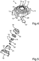
- the operating device 11 has a mounting frame 12 as a supporting base element. This is for example produced as a plastic injection-molded part. He has here four integrally formed fins 13 as guide elements. Each of these fins 13 is in a different direction from the mounting frame 12.
- the OFN module 14 Inside the mounting frame 12 is the OFN module 14 (see. Fig. 5 ), of which in Fig. 4 only the control surface 15, a foil conductor 16 and at the end of a plug 17 can be seen.
- the foil conductor 16 including plug 17 serve for the electrical connection of the OFN module 14.
- the control surface 15 of the OFN module (OFN 14 for short) is surrounded by a ring light guide 18.
- This ring light guide 18 can be made in a desired color, so that the light exiting through it to the outside receives the corresponding color.
- the ring light guide 18 in turn is surrounded by a Lichtabschottelement 19 on the outer circumference.
- This Lichtabschottelement 19 serves to limit the light exit region of the ring light guide 18 upwards.
- the Lichtabschottelement 19 has the function of forming a stop for the ring light guide 18, which in turn forms a stop for the OFN 14.
- the OFN 14 and the ring light guide 18 are thus held upwards by the Lichtabschottelement 19, where the mounting frame 12 is open.
- Fig. 4 is also the end of a snap hook 20 can be seen, which is formed integrally with the Lichtabschottelement 19 and protrudes through the bottom of the mounting frame 12.
- This snap hook 20 cooperates with the bottom of the mounting frame 12 in the sense of a snap connection.
- the snap hook 20 of Lichtabschottelements 19 is pressed by a corresponding recess in the bottom of the mounting frame 12.
- the snap hook can be integrally formed on the mounting frame 12 and enter into a snap connection with a corresponding element of Lichtabschottelements 19.
- FIG. 5 shows the OFN assembly or the operating device 11 next to the mounting frame 12, the OFN 14, the ring conductor 18 and Lichtabschottelement 19 also from a lower light guide 21 and a rubber elastic element 22.
- the lower light guide 21 (in the present document also first Light guide designated) is inserted during assembly in the mounting frame 12.
- In the bottom of the mounting frame 12 are one or more Recesses provided through which light penetrates into the lower light guide 21. He also transports the light to the ring light guide 18. He also has this annular shape and a wall height which corresponds approximately to the cup-shaped mounting frame 12.
- the lower light guide (first light guide element) and the ring light guide 18 (second light guide element) can also be formed in one piece.
- the mounting frame 12 has in its interior a support structure 23.
- this support structure which is similar to the wall of the cup-shaped mounting frame 12, the rubber-elastic element 22 is placed during assembly.
- the rubber-elastic element 22 is then surrounded by the annular lower light guide 21 in the assembled state.
- the rubber-elastic element 22, ie the soft component, is preferably disc-shaped and has, as in connection with Fig. 7 will be explained, if necessary, special contours, in addition to the tolerance compensation to take over other functions such as strain relief.
- the rubber-elastic element 22 also protects the underside of the OFN 14 from damage.
- Fig. 6 now shows the operating device 11 in the installed in a switching device or a switch block state in a vertical section.
- a circuit board 24 On the housing bottom (not shown) of the switching device is a circuit board 24. This carries here embedded in a switch mat 25 two upwardly emitting LEDs 26. In addition, there is a button or switch 27 on the circuit board 24. Immediately above a switching dome 28 of Switch 27 is the support structure 23 of the mounting frame 12. The conically shaped, inner hollow lower light guide 21 surrounds the support structure 23 and protrudes through recesses 29 in the bottom 30 of the mounting frame 12 through to the LEDs 26th
- the disc-shaped rubber-elastic element 22 is located on the support structure 23. If necessary, the rubber-elastic element 22 fixes the lower optical waveguide 21. A printed circuit board 30 of the OFN 14 rests on the rubber-elastic element 22. Then the actual sensor section 31 of the OFN 14 with its operating surface 15 is located.
- the sensor section 31 of the OFN 14 is surrounded on the outer periphery of the ring light guide 18. The latter projects up to the control surface 15 and down to the lower light guide 21.
- the light of the LEDs 26 via the lower light guide 21 up to the ring light guide 18 and there to the surface of the operating device 11 is guided.
- a gap 32 between the lower end of the lower light guide 21 and one of the LEDs 26 is not harmful. This gap 32 is necessary so that the operating device 11 including OFN 14 and mounting frame 12 can perform the necessary stroke of the switch 27.
- Guide elements of the housing 24 for guiding the fins 13 of the mounting frame 12 are in Fig. 6 not recognizable.
- the ring light guide 18 and the lower light guide 21 are surrounded on the outside by the likewise annular Lichtabschottelement 19. It prevents light from being emitted laterally outwards by the light guides. It also holds the entire OFN assembly together.
- a switch panel 33 On the surface there is a switch panel 33, the surface of which is preferably somewhat lower in level than the control surface 15 in the non-actuated state of the operating device 11. This allows the driver to feel the control device easily.
- Fig. 7 is the arrangement of Fig. 6 shown in a rotated by 90 ° section.
- a housing bottom 34 of the switching device can be seen. Perpendicular to the floor is up a bridge 35 from.
- a plug 36 is plugged, which serves to connect the foil conductor 16 of the OFN 14.
- the foil conductor of the OFN 14, which establishes the electrical connection between the OFN and the printed circuit board 24, must allow the relative movement of the operating device or the OFN 14 relative to the printed circuit board 24.
- the foil conductor 16 must be strongly bent directly on the OFN 14, so that it can be guided within the assembly down to the circuit board 24 and the connector 36 arranged there.
- the foil conductor 16 is guided past the inside of the lower light guide 21 to the printed circuit board 24. It runs through a recess in the circuit board 24 through it on its underside.
- the switching mat 25 which protrudes through the recess in the circuit board 24, the film conductor 16 against the web 35 of the housing of the MFS, ie the switching device.
- the mounted on the OFN 14 during assembly ring light guide 18 is a visible and illuminated to the user decorative element around the OFN 14.
- the ring light guide 18 transports the light, as mentioned, from the lower light guide 21 to the surface of the OFN assembly.
- the ring light guide 18 fixes the OFN 14 from above and forms the stop (dashed circle 39) of the OFN assembly at the aperture 33 of the MFS (multifunction switch), ie the switching device.
- the operability of the OFN 14 in the steering wheel 5 is a precisely set projection of the OFN 14 with respect to the diaphragm 33 of the MFS. Since in contrast to consumer electronic should be operated without looking away, the position of the OFN in the steering wheel by the driver must be felt. For a certain supernatant of the OFN against the diaphragm 33 is required, which is already in connection with Fig. 6 was addressed. On the other hand, the supernatant must not be too large, because otherwise the wiping movement of the finger over the OFN control surface 15 is hindered.
- the projection of the OFN 14 to the diaphragm 33 is determined in addition to the target specification of the tolerances of the components that form the tolerance chain from the OFN 14 to the diaphragm 33.
- the ring light guide 18 is placed on the OFN 14 and at the same time forms the stops for the diaphragm 33, there is the tolerance chain with the OFN 14, the ring light guide 18 and the diaphragm 33 of only three parts.
- the tolerance chain is as short as possible and the projection of the OFN 14 to the diaphragm 33 can be tightly tolerated.
- the operating device according to the invention has in summary, inter alia, the advantage that it can be mounted solely by plugging and clips. A gluing process is not necessary.
- the ring light guide 18 is designed as a separate element and its surface and its color can be varied without affecting the other elements.
- the ring light guide can be designed as a cost-effective molded part without further surface treatment or as a sophisticated trim part in translucent chrome look.
- the illumination of the operating device is homogeneous by the existing run lengths of the light and the scattering effect of the light guide.
- the lower light guide is geometrically shaped to realize the homogeneous light distribution.
- the light sources arranged on the printed circuit board can be changed without repercussions on the OFN, which represents a further advantage.
- the supernatant of the OFN to the surrounding switch panel determining tolerance chain is very short. This makes it possible to closely tolerate the corresponding dimension that is important for usability.
- Another advantage of the operating device is the rubber-elastic element which compensates for manufacturing tolerances and fixes the foil conductor of the OFN. Thus, at least in the upper part of the operating device wear on bending and contact points of the film conductor is excluded. The lower tensile load of the film conductor by the switching mat is one of the most important advantages of the above-described embodiment.
- the mounting frame has a suitable height (eg a few millimeters), a sufficient guidance of the operating device is possible in the direction of movement, as a result of which a high-quality feel can be achieved.
Landscapes
- Engineering & Computer Science (AREA)
- Theoretical Computer Science (AREA)
- General Engineering & Computer Science (AREA)
- Mechanical Engineering (AREA)
- Human Computer Interaction (AREA)
- Physics & Mathematics (AREA)
- General Physics & Mathematics (AREA)
- Transportation (AREA)
- Chemical & Material Sciences (AREA)
- Combustion & Propulsion (AREA)
- Switches With Compound Operations (AREA)
- Steering Controls (AREA)
- Push-Button Switches (AREA)
Description
- Die vorliegende Erfindung betrifft eine Bedieneinrichtung zum Einbau in ein Lenkrad eines Kraftfahrzeugs mit einem Befestigungsrahmen und einem optischen Fingernavigationsmodul.
- Aus der
EP 2518592 A2 ist eine Bedieneinrichtung zum Einbau in ein Lenkrad bekannt, wobei die Bedieneinrichtung eine kreisringförmige Taste mit mehreren Segmenten zur Betätigung unterschiedlicher Schaltfunktionen aufweist. Im Innenbereich der Taste ist eine Fläche angeordnet, die mit einem Aktor zur Erzeugung haptischer Rückmeldung an einen Nutzer vorgesehen ist. - Aus der Druckschrift
EP 2 369 818 A1 ist ein optisches Fingernavigationsmodul für ein Mobilfunktelefon bekannt. Es ist ringförmig von einem Leuchtbereich umgeben und besitzt einen chromartigen Ring zur besseren Orientierung für den Benutzer. In den Schalterblock eines Fahrzeuglenkrads kann ein optisches Fingernavigationsmodul (OFN) als Sensor für die Detektion von Fingerbewegungen integriert sein. Daraus gewonnene Steuersignale können beispielsweise zur Steuerung eines Anzeigemenüs im Fahrzeug verwendet werden. Vielfach ist ein derartiges OFN auch gleichzeitig als Taster oder Druckschalter ausgeführt und daher insgesamt senkrecht zur Bedienoberfläche (Schalterblende) betätigbar. - Zur besseren Orientierung ist es vorteilhaft, wenn das Fingernavigationsmodul eine Beleuchtung aufweist. Hierzu hat sich eine Ringbeleuchtung als zweckmäßig erwiesen. In einer qualitativ hochwertigen Ausführung sollte die Ringbeleuchtung homogen sein und in verschiedenen Ausführungsformen bereitstehen. Eine weitere Anforderung hinsichtlich der Praktikabilität bei der Verwendung am Fahrzeuglenkrad ist, dass das als Taster oder Schalter verwendet OFN eine mit einem Kurzhubtaster vergleichbare Betätigungshaptik besitzen sollte. Darüber hinaus ist es wünschenswert, wenn die Bedienfläche des OFN einen engtolerierten Überstand zur umgebenden Schalterblende aufweist. Außerdem sollten die Bewegungen des OFN nicht zu einem Verschleiß der Kontaktierungen des OFN zur Leiterplatte erfolgen. Weiterhin wäre es wünschenswert, wenn die Fixierung des OFN ohne Kleben erfolgen könnte.
- Weitere Bedieneinrichtungen zum Einbau in ein Lenkrad eines Fahrzeugs sind aus
WO 2011/131364 A1 undEP 1 530 227 A1 bekannt. - In der sogenannten "consumer electronic" werden heute OFN 1 eingesetzt, wie sie in der Draufsicht von
Fig. 1 und in der Seitenansicht vonFig. 2 dargestellt sind. Ein derartiges OFN 1 besitzt beispielsweise eine quadratische Bedienfläche 2. Diese ist von einem Beleuchtungsring 3 umgeben, dessen Oberfläche bündig mit derjenigen der Bedienfläche ist. Der Beleuchtungsring 3 ist also in das OFN 1 integriert. Er wird beispielsweise mittels PVD (physical vapor deposition) aufgetragen, damit er im unbeleuchteten Zustand tagsüber wie eine Chromoberfläche wirkt. Nachts wird der Beleuchtungsring 3 beleuchtet. - Auf der Modulunterseite des OFN 1 ist eine Schnappscheibe 4 aufgeklebt. Sie dient als Tasterelement. Die Integration des Beleuchtungsrings 3 und der Schnappscheibe 4 in das OFN 1 ist durch den in der consumer electronic vorhandenen Wunsch nach minimaler Bautiefe motiviert. Diese Ausführungsform hat aber zahlreiche Nachteile, die einer Anwendung eines solchen OFN 1 in einem Fahrzeuglenkrad entgegenstehen.
- Durch die geringe Bautiefe kann die integrierte Ringbeleuchtung nicht homogen ausgeführt werden, da der Abstand der beleuchtenden LED von der auszuleuchtenden Oberfläche zu gering ist. Der Helligkeitsunterschied innerhalb der Ringbeleuchtung beträgt bis zu 50 Prozent, was den Qualitätsanforderungen im Fahrzeug nicht genügt.
- Durch die Integration der Beleuchtung benötigt das OFN im Ausleuchtbereich zudem eine transluzente Oberfläche, die nach aktuellem Stand der Technik noch nicht automotivtauglich ist. Beispielsweise hält diese Oberfläche den im Automobilbereich üblichen Temperaturen und Luftfeuchtigkeiten nicht stand.
- Ein dritter Nachteil ist, dass Farbvarianten in der Beleuchtung immer zu einer Veränderung des OFN selbst führen. Das steht dem im Automobilbereich üblichen Wunsch entgegen, durch die Variation der Beleuchtungsfarbe und den Einsatz von Zierelementen unterschiedliche Fahrzeugklassen und Ausstattungslinien voneinander zu differenzieren und gleichzeitig die technischen Komponenten möglichst unverändert zu verwenden.
- Mit der aufgeklebten Schnappscheibe können zudem die für die Fahrzeuganwendung notwendigen Betätigungskräfte und -wege nicht dargestellt werden, um eine unbeabsichtigte Betätigung in allen Fahrsituationen und unter den dabei möglicherweise auftretenden Vibrationen zu vermeiden, müssen im Fahrzeug die Betätigungskräfte höher und die Betätigungswege länger sein als in der consumer electronic. Diese bedingt wiederum eine gute Führung des OFN, die durch die geringen Bautiefen in der consumer electronic nicht möglich ist.
- Die Aufgabe der vorliegenden Erfindung besteht somit darin, eine Bedieneinrichtung mit einem optischen Fingernavigationsmodul zum Einbau in ein Lenkrad eines Kraftfahrzeugs bereitzustellen, die den Anforderungen im Fahrzeugbau genügt.
- Erfindungsgemäß wird diese Aufgabe gelöst durch eine Bedieneinrichtung nach Anspruch 1. Vorteilhaft Weiterbildungen der Erfindung ergeben sich aus den Unteransprüchen.
- Es wird demnach eine Bedieneinrichtung zum Einbau in ein Lenkrad eines Kraftfahrzeugs mit einem Befestigungsrahmen und einem optischen Fingernavigationsmodul bereitgestellt. In dem Befestigungsrahmen ist ein erstes Lichtleitelement und das optische Fingernavigationsmodul durch ein Lichtabschottelement gehalten. Das Lichtabschottelement ist mittels einer Schnappverbindung an dem Befestigungsrahmen befestigt, und der Befestigungsrahmen weist mindestens ein Führungselement auf, mit dem eine Bewegung des Befestigungsrahmens führbar ist.
- In vorteilhafter Weise werden also ein Befestigungsrahmen und ein Lichtabschottelement quasi als Gehäuse durch eine Schnappverbindung aneinander montiert und in ihrem Inneren ist dadurch das optische Fingernavigationsmodul und ein Lichtleitelement gehalten. Das Lichtabschottelement hat also eine zusätzliche Haltefunktion, wie sie für ein Gehäuse typisch ist. Darüber hinaus besitzt der Befestigungsrahmen auch ein Führungselement, an dem die Bedieneinrichtung bei einer Bewegung geführt werden kann. Damit besitzt der Befestigungsrahmen neben der Haltefunktion auch die Funktion der Bewegungsführung.
- Erfindungsgemäß ist zwischen das optische Fingernavigationsmodul (OFN) und das Lichtabschottelement ein zweites Lichtleitelement eingefügt. Dies hat den Vorteil, dass das erste Lichtleitelement hinsichtlich der Lichtverteilung optimiert werden kann, während das zweite Lichtleitelement beispielsweise hinsichtlich der Farbe optimiert sein und leicht austauschbar gehalten werden kann.
- Das erste Lichtleitelement und das zweite Lichtleitelement können jeweils ringförmig ausgebildet sein und das optische Fingernavigationsmodul umgeben. Durch eine hierdurch mögliche Ringbeleuchtung kann sich der Nutzer der Bedieneinrichtung leichter optisch orientieren und die Bedienfläche des optischen Fingernavigationsmoduls auffinden.
- Vorteilhaft ist außerdem, wenn zwischen dem optischen Fingernavigationsmodul und dem Befestigungsrahmen ein gummielastisches Element angeordnet ist. Dieses auch als Weichkomponente bezeichenbare Element kann sowohl dem Toleranzausgleich als auch der Zugentlastung der elektrischen Anschlüsse des OFN dienen.
- Speziell kann das gummielastische Element einen elektrischen Leiter, insbesondere einen Folienleiter, des optischen Fingernavigationsmoduls zur Zugentlastung an das erste Lichtleitelement drücken. Hierzu kann das gummielastische Element scheibenförmig und entsprechend konturiert ausgebildet sein.
- Speziell kann eine Schaltvorrichtung zum Einbau in ein Lenkrad mit einer oben beschriebenen Bedieneinrichtung und mindestens einer weiteren Bedieneinrichtung bereitgestellt werden. Damit lassen sich Schalterblöcke, wie sie bei modernen Lenkrädern üblich sind, mit der erfindungsgemäßen Bedieneinrichtung realisieren.
- Die Schaltvorrichtung kann mit einem Gehäuse ausgestattet sein, in das die Bedieneinrichtungen eingebaut sind und das ein zu dem Führungselement des Befestigungsrahmens korrespondierendes Führungselement zum Führen des Befestigungsrahmens in dem Gehäuse besitzt. Damit kann ein abgeschlossenes Modul bereitgestellt werden, das mit wenigen Handgriffen in ein Lenkrad einbaubar ist.
- Darüber hinaus kann in dem Gehäuse mindestens eine Lichtquelle angeordnet sein, deren Licht über das erste und zweite Lichtleitelement an die Oberfläche der Bedieneinrichtung geleitet wird. Auf diese Weise ist also die Bedieneinrichtung selbst frei von Lichtquellen, und sie ist dennoch an ihrer Oberfläche beleuchtet.
- Ferner kann an der dem optischen Fingernavigationsmodul abgewandten Seite des Befestigungsrahmens ein Schaltdom eines Schalters angeordnet sein, der durch eine Bewegung des Befestigungsrahmens betätigbar ist. Damit ist die Bedieneinrichtung mit dem optischen Fingernavigationsmodul gleichzeitig als Betätigungselement für einen Schalter nutzbar.
- In einer weiteren Ausführungsform ist an der dem optischen Fingernavigationsmodul abgewandten Seite des Befestigungsrahmens eine Schaltmatte angeordnet, die den Leiter des optischen Fingernavigationsmoduls zur Zugentlastung gegen einen Abschnitt des Gehäuses drückt. Damit erhält die Schaltmatte, die typischerweise aus einem elastischen Material hergestellt ist (z. B. Silikon) zusätzlich die Funktion einer Zugentlastung.
- Die vorliegende Erfindung wird nun anhand der beigefügten Zeichnungen näher erläutert, in denen zeigen:
- Fig. 1
- eine Draufsicht auf ein OFN-Modul nach dem Stand der Technik;
- Fig. 2
- eine Seitenansicht des OFN-Moduls von
Fig. 1 ; - Fig. 3
- eine Skizze eines Lenkrads mit zwei OFN -Modulen;
- Fig. 4
- eine erfindungsgemäße Bedieneinrichtung im zusammengebauten Zustand;
- Fig. 5
- eine Explosionsdarstellung der Bedieneinrichtung von
Fig. 4 ; - Fig. 6
- einen Schnitt durch einen in einen Schaltblock eingebaute Bedieneinrichtung und
- Fig. 7
- ein um 90° gedrehter Schnitt durch die eingebaute Bedieneinrichtung von
Fig. 6 . - Die nachfolgend näher geschilderten Ausführungsbeispiele stellen bevorzugte Ausführungsformen der vorliegenden Erfindung dar.
- In
Fig. 3 ist schematisch ein Lenkrad 5 dargestellt. An dem Lenkrad befinden sich hier in ergonomisch passenden Positionen zwei Schalterblöcke 6, die auch als Multifunktionsschalter (MFS) bezeichnet werden können. In anderen Ausführungsbeispielen ist nur ein einziger derartiger Schalterblock oder mehr als zwei Schalterblöcke bzw. Multifunktionsschalter vorgesehen. - In dem Beispiel von
Fig. 3 besitzt jeder Schalterblock 6 ein optisches Fingernavigationsmodul 1 (OFN). Darüber hinaus besitzen die Schalterblöcke 6 jeweils weitere mechanische Bedienelemente 7. Zur Übermittlung von Daten vom linken Schalterblock 6 zu einer Lenkradelektronik 8 (LRE) dient ein Kabel 9, das an seinen Enden jeweils mit Steckern ausgestattet ist. Analog hierzu erfolgt die Kommunikation von dem rechten Schalterblock 6 zu der Lenkradelektronik 8 über ein Kabel 9. der Signalausgang von der Lenkradelektronik 8 zu beispielsweise einem Mantelrohrschaltermodul (inFig. 3 nicht dargestellt) erfolgt über ein weiteres Kabel 10. - Wie bereits eingangs erwähnt, dient jedes OFN 1 als Sensor für die Detektion von Fingerbewegungen. Die Kabel 9 dienen zur Realisierung einer Datenbusverbindung bzw. Kommunikationseinrichtung zwischen den OFN-Modulen 1 und der Lenkradelektronik 8.
- Das OFN 1 soll z. B. mit einem Taster bzw. Schalter kombiniert werden und darüber hinaus, wie erwähnt, folgende Anforderungen erfüllen:
- homogene Ringbeleuchtung in verschiedenen Ausführungsformen
- mit einem Kurzhubtaster vergleichbare Betätigungshaptik
- engtolerierter Überstand des OFN zur umgebenden Schalterblende
- verschleißfreie Kontaktierung des OFN zur Leiterplatte und
- Fixierung des OFN ohne Kleben
- Kernstück zur Erfüllung dieser Anforderungen ist die im Zusammenhang mit den
Fig. 4 und 5 erläuterte Bedieneinrichtung 11, die auch als OFN-Baugruppe bezeichnet werden kann. Wie ausFig. 4 ersichtlich ist, besitzt die Bedieneinrichtung 11 als tragendes Grundelement einen Befestigungsrahmen 12. Dieser ist beispielsweise als Kunststoffspritzgussteil hergestellt. Er besitzt hier vier einteilig angeformte Finnen 13 als Führungselemente. Jede dieser Finnen 13 steht in einer anderen Richtung von dem Befestigungsrahmen 12 ab. - Im Inneren des Befestigungsrahmens 12 befindet sich das OFN-Modul 14 (vgl.
Fig. 5 ), von dem inFig. 4 lediglich die Bedienfläche 15, ein Folienleiter 16 und an dessen Ende ein Stecker 17 zu erkennen sind. Der Folienleiter 16 einschließlich Stecker 17 dienen zum elektrischen Anschluss des OFN-Moduls 14. - Im eingebauten Zustand ist die Bedienfläche 15 des OFN-Moduls (kurz OFN 14) von einem Ringlichtleiter 18 umgeben. Dieser Ringlichtleiter 18 kann in einer gewünschten Farbe hergestellt sein, so dass das durch ihn hindurch nach außen austretende Licht die entsprechende Färbung erhält.
- Der Ringlichtleiter 18 wiederum ist von einem Lichtabschottelement 19 am Außenumfang umgeben. Dieses Lichtabschottelement 19 dient dazu, den Lichtaustrittsbereich des Ringlichtleiters 18 nach oben hin zu beschränken. Außerdem besitzt das Lichtabschottelement 19 die Funktion, einen Anschlag für den Ringlichtleiter 18 zu bilden, welcher seinerseits einen Anschlag für das OFN 14 bildet. Das OFN 14 und der Ringlichtleiter 18 werden also nach oben hin, wo der Befestigungsrahmen 12 offen ist, durch das Lichtabschottelement 19 gehalten.
- In
Fig. 4 ist außerdem das Ende eines Schnapphakens 20 zu erkennen, der einteilig mit dem Lichtabschottelement 19 gebildet ist und durch den Boden des Befestigungsrahmens 12 hindurchragt. Dieser Schnapphaken 20 wirkt mit dem Boden des Befestigungsrahmens 12 im Sinne einer Schnappverbindung zusammen. Zur Montage wird der Schnapphaken 20 des Lichtabschottelements 19 durch eine entsprechende Aussparung im Boden des Befestigungsrahmens 12 gedrückt. Dort schnappt er in üblicher Weise in seine Endposition und hintergreift dabei eine Kante des Befestigungsrahmens 12. Umgekehrt kann bei einer alternativen Ausführungsform auch der Schnapphaken einteilig an dem Befestigungsrahmen 12 angeformt sein und mit einem korrespondierenden Element des Lichtabschottelements 19 eine Schnappverbindung eingehen. - Wie aus
Fig. 5 hervorgeht, besteht die OFN-Baugruppe bzw. die Bedieneinrichtung 11 neben dem Befestigungsrahmen 12, dem OFN 14, dem Ringleiter 18 und dem Lichtabschottelement 19 außerdem aus einem unteren Lichtleiter 21 und einem gummielastischen Element 22. Der untere Lichtleiter 21 (im vorliegenden Dokument auch erstes Lichtleitelement bezeichnet) wird bei der Montage in dem Befestigungsrahmen 12 gesteckt. In dem Boden des Befestigungsrahmens 12 sind eine oder mehrere Aussparungen vorgesehen, durch die hindurch Licht in den unteren Lichtleiter 21 dringt. Er transportiert das Licht zum Ringlichtleiter 18. Er besitzt hierzu ebenfalls ringförmige Gestalt und eine Wandhöhe, die in etwa der des topfförmigen Befestigungsrahmens 12 entspricht. Prinzipiell können der untere Lichtleiter (erstes Lichtleitelement) und der Ringlichtleiter 18 (zweites Lichtleitelement) auch einteilig gebildet sein. - Wie aus
Fig. 5 ersichtlich ist, besitzt der Befestigungsrahmen 12 in seinem Inneren eine Stützstruktur 23. Auf diese Stützstruktur, die ähnlich hoch ist wie die Wand des topfförmigen Befestigungsrahmens 12 wird bei der Montage das gummielastische Element 22 aufgelegt. Das gummielastische Element 22 wird dann im montierten Zustand von dem ringförmigen unteren Lichtleiter 21 umgeben. Das gummielastische Element 22, d. h. die Weichkomponente, ist vorzugsweise scheibenförmig ausgebildet und besitzt, wie im Zusammenhang mitFig. 7 erläutert werden wird, ggf. spezielle Konturen, um neben dem Toleranzausgleich auch andere Funktionen wie Zugentlastung zu übernehmen. Dabei schützt das gummielastische Element 22 auch die Unterseite des OFN 14 vor Beschädigung. -
Fig. 6 zeigt nun die Bedieneinrichtung 11 im in eine Schaltvorrichtung bzw. einen Schalterblock eingebauten Zustand in einem vertikalen Schnitt. - Auf dem Gehäuseboden (nicht dargestellt) der Schaltvorrichtung befindet sich eine Leiterplatte 24. Diese trägt hier eingebettet in eine Schaltermatte 25 zwei nach oben abstrahlende LEDs 26. Außerdem befindet sich ein Taster bzw. Schalter 27 auf der Leiterplatte 24. Unmittelbar über einem Schaltdom 28 des Schalters 27 befindet sich die Stützstruktur 23 des Befestigungsrahmens 12. Der konisch geformte, innen hohle untere Lichtleiter 21 umgibt die Stützstruktur 23 und ragt durch Aussparungen 29 im Boden 30 des Befestigungsrahmens 12 hindurch zu den LEDs 26.
- Auf der Stützstruktur 23 liegt das scheibenförmige gummielastische Element 22 auf. Das gummielastische Element 22 fixiert ggf. den unteren Lichtleiter 21. Auf dem gummielastischen Element 22 liegt eine Leiterplatte 30 des OFN 14 auf. Darauf befindet sich der eigentliche Sensorabschnitt 31 des OFN 14 mit seiner Bedienfläche 15.
- Der Sensorabschnitt 31 des OFN 14 ist am Außenumfang von dem Ringlichtleiter 18 umgeben. Letzterer ragt nach oben bis zur Bedienfläche 15 und nach unten bis zum unteren Lichtleitelement 21. Somit wird das Licht der LEDs 26 über den unteren Lichtleiter 21 nach oben zum Ringlichtleiter 18 und dort bis zur Oberfläche der Bedieneinrichtung 11 geführt. Ein Spalt 32 zwischen dem unteren Ende des unteren Lichtleiters 21 und einer der LEDs 26 ist dabei nicht schädlich. Dieser Spalt 32 ist notwendig, damit die Bedieneinrichtung 11 einschließlich OFN 14 und Befestigungsrahmen 12 den notwendigen Hub des Schalters 27 vollführen kann. Führungselemente des Gehäuses 24 zum Führen der Finnen 13 des Befestigungsrahmens 12 sind in
Fig. 6 nicht zu erkennen. - Der Ringlichtleiter 18 und der untere Lichtleiter 21 sind außen von dem ebenfalls ringförmigen Lichtabschottelement 19 umgeben. Es verhindert, dass Licht von den Lichtleitern seitlich nach außen abgestrahlt wird. Außerdem hält es die gesamte OFN-Baugruppe zusammen.
An der Oberfläche befindet sich eine Schalterblende 33, deren Oberfläche im Niveau vorzugsweise etwas niedriger liegt als die Bedienfläche 15 im nichtbetätigten Zustand der Bedieneinrichtung 11. Dadurch kann der Fahrer die Bedieneinrichtung leicht ertasten. - In
Fig. 7 ist die Anordnung vonFig. 6 in einem um 90 ° gedrehten Schnitt dargestellt. In dieser Ansicht ist auch ein Gehäuseboden 34 der Schaltvorrichtung zu erkennen. Senkrecht von dem Boden steht nach oben ein Steg 35 ab. An der Unterseite der Leiterplatte 24 ist ein Stecker 36 aufgesteckt, der zum Anschluss des Folienleiters 16 des OFN 14 dient. Der Folienleiter der OFN 14, der die elektrische Verbindung zwischen dem OFN und der Leiterplatte 24 herstellt, muss die relative Bewegung der Bedieneinrichtung bzw. des OFN 14 gegenüber der Leiterplatte 24 ermöglichen. Aus Bauraumgründen muss der Folienleiter 16 direkt am OFN 14 stark abgewinkelt werden, damit er innerhalb der Baugruppe nach unten zur Leiterplatte 24 und dem dort angeordneten Stecker 36 geführt werden kann. Insbesondere wird der Folienleiter 16 an der Innenseite des unteren Lichtleiters 21 vorbei zur Leiterplatte 24 geführt. Er verläuft dabei durch eine Aussparung der Leiterplatte 24 durch sie hindurch auf ihre Unterseite. - Um einen Verschleiß des Folienleiters 16 insbesondere im Bereich seiner Enden bzw. Kontaktstellen durch die Betätigung und Bewegung der gesamten OFN-Baugruppe, d. h. der Bedieneinrichtung 11 zu vermeiden, müssen Bewegungen des Folienleiters 16 am Abgang vom OFN 14 und am Stecker 36 auf der Leiterplatte 24 vermieden werden. Deshalb werden durch die Weichkomponente, d. h. das gummielastische Element 22 eine obere Zugentlastung (realisiert in dem gestrichelten Kreis 37) und durch die Schaltmatte 25 eine untere Zugentlastung (siehe gestrichelter Kreis 38) realisiert. Bei der oberen Zugentlastung 37 presst das gummielastische Element 22 den Folienleiter 16 gegen die Innenseite des unteren Lichtleiters 21. Bei der unteren Zugentlastung presst die Schaltmatte 25, die durch die Aussparung in der Leiterplatte 24 ragt, den Folienleiter 16 gegen den Steg 35 des Gehäuses des MFS, d. h. der Schaltvorrichtung. Die vorzugsweise aus elastischem Silikon gebildete Schaltmatte 25 hat also neben ihrer eigentlichen Funktion als Abdichtung der Schaltelemente die zusätzliche Funktion einer Zugentlastung.
- Der bei der Montage auf das OFN 14 aufgesetzte Ringlichtleiter 18 ist ein für den Benutzer sichtbares und beleuchtetes Zierelement um das OFN 14. Der Ringlichtleiter 18 transportiert das Licht, wie erwähnt, vom unteren Lichtleiter 21 zur Oberfläche der OFN-Baugruppe. Gleichzeitig fixiert der Ringlichtleiter 18 das OFN 14 von oben und bildet den Anschlag (gestrichelter Kreis 39) der OFN-Baugruppe an der Blende 33 des MFS (Multifunktionsschalter), also der Schaltvorrichtung.
- Wichtig für die Bedienbarkeit des OFN 14 im Lenkrad 5 ist ein genau eingestellter Überstand des OFN 14 gegenüber der Blende 33 des MFS. Da im Gegensatz zur consumer electronic ohne Blickabwendung bedient werden soll, muss die Position des OFN im Lenkrad vom Fahrer erfühlbar sein. Dafür ist ein gewisser Überstand des OFN gegenüber der Blende 33 erforderlich, was bereits in Zusammenhang mit
Fig. 6 angesprochen wurde. Auf der anderen Seite darf der Überstand auch nicht zu groß sein, weil sonst die Wischbewegung des Fingers über die OFN-Bedienfläche 15 behindert wird. Der Überstand des OFN 14 zur Blende 33 wird neben der Sollvorgabe auch von den Toleranzen der Bauteile bestimmt, die die Toleranzkette vom OFN 14 bis zur Blende 33 bilden. Indem der Ringlichtleiter 18 auf das OFN 14 aufgesetzt wird und gleichzeitig die Anschläge zur Blende 33 bildet, besteht die Toleranzkette mit dem OFN 14, dem Ringlichtleiter 18 und der Blende 33 aus lediglich drei Teilen. Damit ist die Toleranzkette so kurz wie möglich und der Überstand des OFN 14 zur Blende 33 kann eng toleriert werden. - Die erfindungsgemäße Bedieneinrichtung, mit der die entsprechende Schaltvorrichtung hergestellt werden kann, hat zusammenfassend u. a. den Vorteil, dass sie allein durch Stecken und Clipsen montiert werden kann. Ein Klebeprozess ist also nicht notwendig. Der Ringlichtleiter 18 ist als separates Element ausgeführt und seine Oberfläche sowie seine Farbgebung kann ohne Rückwirkung auf die anderen Elemente variiert werden. Beispielsweise kann der Ringlichtleiter als kostengünstiges Spritzteil ohne weitere Oberflächenbehandlung oder als anspruchsvolles Zierteil in transluzenter Chromoptik ausgeführt werden.
- Die Ausleuchtung der Bedienvorrichtung ist durch die vorhandenen Lauflängen des Lichts und die Streuwirkung der Lichtleiter homogen. Der untere Lichtleiter ist zur Realisierung der homogenen Lichtverteilung geometrisch entsprechend geformt. Die auf der Leiterplatte angeordneten Lichtquellen können ohne Rückwirkungen auf das OFN verändert werden, was einen weiteren Vorteil darstellt.
- Vorteilhaft ist außerdem, dass die den Überstand des OFN zur umgebenden Schalterblende bestimmende Toleranzkette sehr kurz ist. Damit kann das entsprechende, für die Bedienbarkeit wichtige Maß eng toleriert werden.
Einen weiteren Vorteil der Bedieneinrichtung stellt das gummielastische Element dar, das Fertigungstoleranzen ausgleicht und den Folienleiter des OFN fixiert. Damit ist zumindest im oberen Bereich der Bedieneinrichtung ein Verschleiß an Biege- und Kontaktstellen des Folienleiters ausgeschlossen. Auch die untere Zugbelastung des Folienleiters durch die Schaltmatte zählt zu den wichtigsten Vorteilen des oben geschilderten Ausführungsbeispiels. - Da der Befestigungsrahmen eine geeignete Höhe (z. B. wenige Millimeter) besitzt, ist in Bewegungsrichtung eine ausreichende Führung der Bedieneinrichtung möglich, wodurch eine hochwertige Haptik realisiert werden kann.
Claims (9)
- Bedieneinrichtung (11) zum Einbau in ein Lenkrad eines Kraftfahrzeugs mit- einem Befestigungsrahmen (12) und- einem Lichtabschottelement (19) das mittels einer Schnappverbindung an dem Befestigungsrahmen (12) befestigt ist,
dadurch gekennzeichnet, dass- der Befestigungsrahmen (12) mindestens ein Führungselement (13) aufweist, mit dem eine Bewegung der den Befestigungsrahmen (12) umfassenden Bedieneinrichtung (11) führbar ist,- die Bedieneinrichtung (11) ein optisches Fingernavigationsmodul (14) umfasst und- in dem Befestigungsrahmen (12) ein erstes Lichtleitelement (21) und das optische Fingernavigationsmodul (14) durch das Lichtabschottelement (19) gehalten sind, wobei zwischen das optische Fingernavigationsmodul (14) und das Lichtabschottelement (19) ein zweites Lichtleitelement (18) eingefügt ist. - Bedieneinrichtung (11) nach Anspruch 1,
dadurch gekennzeichnet, dass
das erste Lichtleitelement (21) und das zweite Lichtleitelement (18) jeweils ringförmig ausgebildet sind und das optische Fingernavigationsmodul (14) umgeben. - Bedieneinrichtung (11) nach einem der vorhergehenden Ansprüche,
dadurch gekennzeichnet, dass
zwischen dem optischen Fingernavigationsmodul (14) und dem Befestigungsrahmen (12) ein gummielastisches Element (22) angeordnet ist. - Bedieneinrichtung (11) nach Anspruch 3,
dadurch gekennzeichnet, dass
das gummielastische Element (22) einen elektrischen Leiter, insbesondere einen Folienleiter (16), des optischen Fingernavigationsmoduls (14) zur Zugentlastung an das erste Lichtleitelement (21) drückt. - Schaltvorrichtung zum Einbau in ein Lenkrad mit einer Bedieneinrichtung (11) nach einem der vorhergehenden Ansprüche und mindestens einer weiteren Bedieneinrichtung (7).
- Schaltvorrichtung nach Anspruch 5,
dadurch gekennzeichnet, dass
sie mit einem Gehäuse ausgestattet ist, in das die Bedieneinrichtungen (11, 7) eingebaut
sind und das ein zu dem Führungselement (13) des Befestigungsrahmens (12) korrespondierendes Führungselement zum Führen des Befestigungsrahmens in dem Gehäuse besitzt. - Schaltvorrichtung nach Anspruch 5 oder 6 und mit der Bedieneinrichtung (11) nach Anspruch 2,
dadurch gekennzeichnet, dass
in dem Gehäuse mindestens eine Lichtquelle (26) angeordnet ist, deren Licht über das erste und zweite Lichtleitelement (21, 18) an die Oberfläche der Bedieneinrichtung (11) geleitet wird. - Schaltvorrichtung nach einem der Ansprüche 5 bis 7,
dadurch gekennzeichnet, dass
an der dem optischen Fingernavigationsmodul (14) abgewandten Seite des Befestigungsrahmens (12) ein Schaltdom (32) eines Schalters angeordnet ist, der durch eine Bewegung des Befestigungsrahmens (12) betätigbar ist. - Schaltvorrichtung nach einem der Ansprüche 6 bis 8,
mit der Bedieneinrichtung (11) nach Anspruch 4,
dadurch gekennzeichnet, dass
an der dem optischen Fingernavigationsmodul (14) abgewandten Seite des Befestigungsrahmens (12) eine Schaltmatte (25) angeordnet ist, die den elektrischen Leiter des
optischen Fingernavigationsmoduls (14) zur Zugentlastung gegen einen Abschnitt des Gehäuses (34) drückt.
Applications Claiming Priority (2)
| Application Number | Priority Date | Filing Date | Title |
|---|---|---|---|
| DE102013001876.5A DE102013001876A1 (de) | 2013-02-02 | 2013-02-02 | Bedieneinrichtung mit optischem Fingernavigationsmodul für ein Lenkrad |
| PCT/EP2014/000133 WO2014117918A1 (de) | 2013-02-02 | 2014-01-18 | Bedieneinrichtung mit optischem fingernavigationsmodul für ein lenkrad |
Publications (2)
| Publication Number | Publication Date |
|---|---|
| EP2951664A1 EP2951664A1 (de) | 2015-12-09 |
| EP2951664B1 true EP2951664B1 (de) | 2018-10-10 |
Family
ID=50002673
Family Applications (1)
| Application Number | Title | Priority Date | Filing Date |
|---|---|---|---|
| EP14701285.0A Active EP2951664B1 (de) | 2013-02-02 | 2014-01-18 | Bedieneinrichtung mit optischem fingernavigationsmodul für ein lenkrad |
Country Status (5)
| Country | Link |
|---|---|
| US (1) | US9793069B2 (de) |
| EP (1) | EP2951664B1 (de) |
| CN (1) | CN105027036B (de) |
| DE (1) | DE102013001876A1 (de) |
| WO (1) | WO2014117918A1 (de) |
Families Citing this family (11)
| Publication number | Priority date | Publication date | Assignee | Title |
|---|---|---|---|---|
| US9730340B1 (en) * | 2014-09-30 | 2017-08-08 | Apple Inc. | Electronic device with array of rotationally mounted components |
| DE102014220369A1 (de) | 2014-10-08 | 2016-04-14 | Continental Automotive Gmbh | Betätigungselement mit Koronabeleuchtung |
| DE102016200580A1 (de) * | 2016-01-19 | 2017-07-20 | Volkswagen Aktiengesellschaft | Beleuchtungsvorrichtung für ein Fahrzeug |
| JP7083226B2 (ja) | 2016-06-10 | 2022-06-10 | 任天堂株式会社 | ゲームコントローラ |
| EP3254739B1 (de) | 2016-06-10 | 2020-03-25 | Nintendo Co., Ltd. | Spielsteuergerät |
| WO2017212663A1 (ja) | 2016-06-10 | 2017-12-14 | 任天堂株式会社 | ゲームコントローラ |
| JP6677580B2 (ja) * | 2016-06-10 | 2020-04-08 | 任天堂株式会社 | ゲームコントローラ |
| EP3736985A1 (de) * | 2019-05-10 | 2020-11-11 | Captron Electronic GmbH | Beleuchteter schalter |
| USD997107S1 (en) * | 2020-12-04 | 2023-08-29 | Zoox, Inc. | Door interface system having an animated visual indicator |
| DE202021103152U1 (de) * | 2021-06-10 | 2021-06-17 | elobau GmbH & Co.KG | Gedichtetes Daumenrad |
| US20240177518A1 (en) * | 2022-11-24 | 2024-05-30 | Pixart Imaging Inc. | Signal integration system and capacitive touch control device |
Family Cites Families (31)
| Publication number | Priority date | Publication date | Assignee | Title |
|---|---|---|---|---|
| DE2613525A1 (de) * | 1976-03-30 | 1977-10-06 | Bosch Gmbh Robert | Konsole fuer betriebsschalter eines kraftfahrzeuges |
| JPS56135349A (en) * | 1980-03-25 | 1981-10-22 | Nissan Motor Co Ltd | Switch device on steering wheel |
| US4616224A (en) * | 1983-03-16 | 1986-10-07 | Sheller-Globe Corporation | Multifunction steering wheel |
| US4811175A (en) * | 1986-07-09 | 1989-03-07 | Desmet Gregory L | Illuminated switch |
| US5631454A (en) * | 1995-09-27 | 1997-05-20 | Trw Inc. | Switch and instrument panel interlock latch controlled by switch actuator |
| US20010038381A1 (en) * | 1997-11-17 | 2001-11-08 | Richard W. Griencewic | Illuminated pointing device for a computer |
| JP2000207916A (ja) * | 1999-01-11 | 2000-07-28 | Yamaha Corp | 照明装置および操作装置 |
| DE29914191U1 (de) * | 1999-08-13 | 1999-11-11 | Dewert Antriebs- Und Systemtechnik Gmbh & Co. Kg, 32278 Kirchlengern | Handbedienungseinrichtung |
| JP2002062983A (ja) * | 2000-08-21 | 2002-02-28 | Hitachi Ltd | ポインティングデバイス |
| TW588812U (en) * | 2001-12-14 | 2004-05-21 | Lite On Technology Corp | Knob structure |
| JP4295468B2 (ja) * | 2001-12-21 | 2009-07-15 | ポリマテック株式会社 | 照光式押釦スイッチ用カバー部材 |
| US6791046B1 (en) * | 2002-05-28 | 2004-09-14 | Corey T. King | Switch assembly |
| JP4184926B2 (ja) * | 2003-11-10 | 2008-11-19 | アルプス電気株式会社 | ステアリングスイッチ装置 |
| JP4317741B2 (ja) * | 2003-12-24 | 2009-08-19 | アルプス電気株式会社 | 4方向スイッチ装置 |
| US7581342B2 (en) * | 2005-08-24 | 2009-09-01 | Calsonic Kansei Corporation | Display device |
| US7072533B1 (en) * | 2005-09-26 | 2006-07-04 | Visteon Global Technologies, Inc. | Automotive optical touch sensitive switch method |
| JP4708220B2 (ja) * | 2006-03-03 | 2011-06-22 | 富士通株式会社 | 照明装置及びこれを用いた撮像装置 |
| US7995034B2 (en) * | 2006-06-22 | 2011-08-09 | Microsoft Corporation | Input device having a presence sensor |
| JP2009123628A (ja) * | 2007-11-16 | 2009-06-04 | Toyo Denso Co Ltd | ステアリングホイール用レバースイッチの構造 |
| JP5027061B2 (ja) * | 2008-06-16 | 2012-09-19 | 株式会社東海理化電機製作所 | スイッチ装置 |
| WO2011066647A1 (en) * | 2009-12-03 | 2011-06-09 | Omron Dualtec Automotive Electronics Inc. | Electrical switch assembly comprising a 5-way toggle mechanism and illuminated flexible layer |
| EP2369817A1 (de) | 2010-02-25 | 2011-09-28 | Research In Motion Limited | Beleuchtetes optisches Navigationsmodul |
| DE102011018234A1 (de) * | 2010-04-21 | 2012-02-02 | Marquardt Gmbh | Bedienvorrichtung |
| JP2012208762A (ja) * | 2011-03-30 | 2012-10-25 | Nippon Seiki Co Ltd | タッチパネル入力操作装置 |
| EP2518592B1 (de) * | 2011-04-25 | 2017-07-26 | Daesung Electric Co., Ltd | Haptische Lenkradschaltvorrichtung |
| US8567997B2 (en) * | 2011-09-06 | 2013-10-29 | Asia Optical International Ltd. | Single piece light guide having light rod and lens |
| CN102407876A (zh) * | 2011-10-11 | 2012-04-11 | 东莞市华鸿塑料机械厂 | 一种具有光学手指导航组件的方向盘 |
| EP2587510B1 (de) * | 2011-10-28 | 2018-02-28 | BlackBerry Limited | Schlüsselanordnung für eine elektronische Vorrichtung |
| JP5986430B2 (ja) * | 2012-05-31 | 2016-09-06 | 矢崎総業株式会社 | 照光表示スイッチ装置 |
| US20140267166A1 (en) * | 2013-03-12 | 2014-09-18 | Qualcomm Mems Technologies, Inc. | Combined optical touch and gesture sensing |
| KR102203273B1 (ko) * | 2014-06-17 | 2021-01-14 | 현대모비스 주식회사 | 버튼의 조명장치 |
-
2013
- 2013-02-02 DE DE102013001876.5A patent/DE102013001876A1/de not_active Withdrawn
-
2014
- 2014-01-18 CN CN201480006814.4A patent/CN105027036B/zh active Active
- 2014-01-18 WO PCT/EP2014/000133 patent/WO2014117918A1/de not_active Ceased
- 2014-01-18 EP EP14701285.0A patent/EP2951664B1/de active Active
- 2014-01-18 US US14/765,290 patent/US9793069B2/en active Active
Non-Patent Citations (1)
| Title |
|---|
| None * |
Also Published As
| Publication number | Publication date |
|---|---|
| WO2014117918A1 (de) | 2014-08-07 |
| CN105027036A (zh) | 2015-11-04 |
| EP2951664A1 (de) | 2015-12-09 |
| US9793069B2 (en) | 2017-10-17 |
| DE102013001876A1 (de) | 2014-08-07 |
| US20150371794A1 (en) | 2015-12-24 |
| CN105027036B (zh) | 2018-06-01 |
Similar Documents
| Publication | Publication Date | Title |
|---|---|---|
| EP2951664A1 (de) | Bedieneinrichtung mit optischem fingernavigationsmodul für ein lenkrad | |
| EP2355356B1 (de) | Kapazitiver Berührungs- und/oder Annäherungsschalter | |
| EP2979288B1 (de) | Tastenmodul für eine taste einer tastatur und verfahren zum herstellen eines tastenmoduls für eine taste einer tastatur | |
| DE19704253C2 (de) | Bedieneinheit für eine Kfz-Komponente, insbesondere für das Steuergerät einer Kfz-Klimaanlage | |
| DE102006041797B4 (de) | Tasten- und Hohllichtleitermechanismus sowie entsprechende Anordnung | |
| DE112008003051T5 (de) | Einrichtung zur Beleuchtung von Zieloberflächen, einen integrierten Schalter beinhaltend | |
| WO2007053966A2 (de) | Integrierter schalter respektive integrierte taste | |
| DE102008055865A1 (de) | Taster zum Bedienen eines elektrischen Verbrauchers in einem Fahrzeug, insbesondere zur Integration in einem Zierteil | |
| DE112010004640T5 (de) | Aufbau eines elektrischen Schalters aufweisend einen5-Wege-Toogle-Mechanismus und eine beleuchtete, flexible Schicht | |
| WO2018108398A1 (de) | Bediensystem für ein kraftfahrzeug, interieurteil und lenkrad mit einem bediensystem | |
| DE102009056212A1 (de) | Elektronisches Bauteil hergestellt durch Spritzgießen, Verfahren und Werkzeug zur Herstellung desselben und elektronisches Gerät zur Verwendung desselben | |
| DE102010033390B4 (de) | Kapazitiver Berührungs- und/oder Annäherungsschalter | |
| EP1212765B1 (de) | Schalter zur anordnung an einem designelement im fahrgastraum eines kraftfahrzeugs | |
| WO2018234360A1 (de) | Kraftfahrzeugbedienvorrichtung | |
| WO2012104289A2 (de) | Oberflächen integrierte schaltelementanordung | |
| DE102008060354A1 (de) | Schalteranordnung | |
| DE102013215719B3 (de) | Tastermodul | |
| DE102018108299B4 (de) | Bedieneinrichtung | |
| DE102021005902B3 (de) | Bedieneinheit, deren Verwendung und ein entsprechendes Herstellungsverfahren | |
| DE102014201523B4 (de) | Bedieneinheit insbesondere für eine Fahrzeugkomponente | |
| DE102011118347A1 (de) | Schaltelement | |
| DE102013211276B3 (de) | Betätigungselementanordnung, insbesondere zur Betätigung einer Fahrzeugkomponente | |
| DE102011107623A1 (de) | Bedienfeld zur Anordnung in einem Fahrzeuginnenraum eines Fahrzeuges | |
| EP0965899B1 (de) | Fronteinheit für ein elektronisches Gerät | |
| DE102007045871B4 (de) | Tastenfeld |
Legal Events
| Date | Code | Title | Description |
|---|---|---|---|
| PUAI | Public reference made under article 153(3) epc to a published international application that has entered the european phase |
Free format text: ORIGINAL CODE: 0009012 |
|
| 17P | Request for examination filed |
Effective date: 20150707 |
|
| AK | Designated contracting states |
Kind code of ref document: A1 Designated state(s): AL AT BE BG CH CY CZ DE DK EE ES FI FR GB GR HR HU IE IS IT LI LT LU LV MC MK MT NL NO PL PT RO RS SE SI SK SM TR |
|
| AX | Request for extension of the european patent |
Extension state: BA ME |
|
| DAX | Request for extension of the european patent (deleted) | ||
| REG | Reference to a national code |
Ref country code: DE Ref legal event code: R079 Ref document number: 502014009701 Country of ref document: DE Free format text: PREVIOUS MAIN CLASS: G06F0003035400 Ipc: B60K0037060000 |
|
| GRAP | Despatch of communication of intention to grant a patent |
Free format text: ORIGINAL CODE: EPIDOSNIGR1 |
|
| STAA | Information on the status of an ep patent application or granted ep patent |
Free format text: STATUS: GRANT OF PATENT IS INTENDED |
|
| RIC1 | Information provided on ipc code assigned before grant |
Ipc: G06F 3/0354 20130101ALI20180404BHEP Ipc: H01H 13/02 20060101ALI20180404BHEP Ipc: B60K 37/06 20060101AFI20180404BHEP |
|
| INTG | Intention to grant announced |
Effective date: 20180430 |
|
| GRAS | Grant fee paid |
Free format text: ORIGINAL CODE: EPIDOSNIGR3 |
|
| GRAA | (expected) grant |
Free format text: ORIGINAL CODE: 0009210 |
|
| STAA | Information on the status of an ep patent application or granted ep patent |
Free format text: STATUS: THE PATENT HAS BEEN GRANTED |
|
| AK | Designated contracting states |
Kind code of ref document: B1 Designated state(s): AL AT BE BG CH CY CZ DE DK EE ES FI FR GB GR HR HU IE IS IT LI LT LU LV MC MK MT NL NO PL PT RO RS SE SI SK SM TR |
|
| REG | Reference to a national code |
Ref country code: GB Ref legal event code: FG4D Free format text: NOT ENGLISH |
|
| REG | Reference to a national code |
Ref country code: CH Ref legal event code: EP Ref country code: AT Ref legal event code: REF Ref document number: 1050818 Country of ref document: AT Kind code of ref document: T Effective date: 20181015 |
|
| REG | Reference to a national code |
Ref country code: DE Ref legal event code: R096 Ref document number: 502014009701 Country of ref document: DE Ref country code: IE Ref legal event code: FG4D Free format text: LANGUAGE OF EP DOCUMENT: GERMAN |
|
| REG | Reference to a national code |
Ref country code: NL Ref legal event code: MP Effective date: 20181010 |
|
| REG | Reference to a national code |
Ref country code: LT Ref legal event code: MG4D |
|
| PG25 | Lapsed in a contracting state [announced via postgrant information from national office to epo] |
Ref country code: NL Free format text: LAPSE BECAUSE OF FAILURE TO SUBMIT A TRANSLATION OF THE DESCRIPTION OR TO PAY THE FEE WITHIN THE PRESCRIBED TIME-LIMIT Effective date: 20181010 |
|
| PG25 | Lapsed in a contracting state [announced via postgrant information from national office to epo] |
Ref country code: LV Free format text: LAPSE BECAUSE OF FAILURE TO SUBMIT A TRANSLATION OF THE DESCRIPTION OR TO PAY THE FEE WITHIN THE PRESCRIBED TIME-LIMIT Effective date: 20181010 Ref country code: LT Free format text: LAPSE BECAUSE OF FAILURE TO SUBMIT A TRANSLATION OF THE DESCRIPTION OR TO PAY THE FEE WITHIN THE PRESCRIBED TIME-LIMIT Effective date: 20181010 Ref country code: PL Free format text: LAPSE BECAUSE OF FAILURE TO SUBMIT A TRANSLATION OF THE DESCRIPTION OR TO PAY THE FEE WITHIN THE PRESCRIBED TIME-LIMIT Effective date: 20181010 Ref country code: HR Free format text: LAPSE BECAUSE OF FAILURE TO SUBMIT A TRANSLATION OF THE DESCRIPTION OR TO PAY THE FEE WITHIN THE PRESCRIBED TIME-LIMIT Effective date: 20181010 Ref country code: ES Free format text: LAPSE BECAUSE OF FAILURE TO SUBMIT A TRANSLATION OF THE DESCRIPTION OR TO PAY THE FEE WITHIN THE PRESCRIBED TIME-LIMIT Effective date: 20181010 Ref country code: BG Free format text: LAPSE BECAUSE OF FAILURE TO SUBMIT A TRANSLATION OF THE DESCRIPTION OR TO PAY THE FEE WITHIN THE PRESCRIBED TIME-LIMIT Effective date: 20190110 Ref country code: IS Free format text: LAPSE BECAUSE OF FAILURE TO SUBMIT A TRANSLATION OF THE DESCRIPTION OR TO PAY THE FEE WITHIN THE PRESCRIBED TIME-LIMIT Effective date: 20190210 Ref country code: FI Free format text: LAPSE BECAUSE OF FAILURE TO SUBMIT A TRANSLATION OF THE DESCRIPTION OR TO PAY THE FEE WITHIN THE PRESCRIBED TIME-LIMIT Effective date: 20181010 Ref country code: NO Free format text: LAPSE BECAUSE OF FAILURE TO SUBMIT A TRANSLATION OF THE DESCRIPTION OR TO PAY THE FEE WITHIN THE PRESCRIBED TIME-LIMIT Effective date: 20190110 |
|
| PG25 | Lapsed in a contracting state [announced via postgrant information from national office to epo] |
Ref country code: GR Free format text: LAPSE BECAUSE OF FAILURE TO SUBMIT A TRANSLATION OF THE DESCRIPTION OR TO PAY THE FEE WITHIN THE PRESCRIBED TIME-LIMIT Effective date: 20190111 Ref country code: SE Free format text: LAPSE BECAUSE OF FAILURE TO SUBMIT A TRANSLATION OF THE DESCRIPTION OR TO PAY THE FEE WITHIN THE PRESCRIBED TIME-LIMIT Effective date: 20181010 Ref country code: RS Free format text: LAPSE BECAUSE OF FAILURE TO SUBMIT A TRANSLATION OF THE DESCRIPTION OR TO PAY THE FEE WITHIN THE PRESCRIBED TIME-LIMIT Effective date: 20181010 Ref country code: PT Free format text: LAPSE BECAUSE OF FAILURE TO SUBMIT A TRANSLATION OF THE DESCRIPTION OR TO PAY THE FEE WITHIN THE PRESCRIBED TIME-LIMIT Effective date: 20190210 Ref country code: AL Free format text: LAPSE BECAUSE OF FAILURE TO SUBMIT A TRANSLATION OF THE DESCRIPTION OR TO PAY THE FEE WITHIN THE PRESCRIBED TIME-LIMIT Effective date: 20181010 |
|
| REG | Reference to a national code |
Ref country code: DE Ref legal event code: R097 Ref document number: 502014009701 Country of ref document: DE |
|
| PG25 | Lapsed in a contracting state [announced via postgrant information from national office to epo] |
Ref country code: DK Free format text: LAPSE BECAUSE OF FAILURE TO SUBMIT A TRANSLATION OF THE DESCRIPTION OR TO PAY THE FEE WITHIN THE PRESCRIBED TIME-LIMIT Effective date: 20181010 Ref country code: IT Free format text: LAPSE BECAUSE OF FAILURE TO SUBMIT A TRANSLATION OF THE DESCRIPTION OR TO PAY THE FEE WITHIN THE PRESCRIBED TIME-LIMIT Effective date: 20181010 Ref country code: CZ Free format text: LAPSE BECAUSE OF FAILURE TO SUBMIT A TRANSLATION OF THE DESCRIPTION OR TO PAY THE FEE WITHIN THE PRESCRIBED TIME-LIMIT Effective date: 20181010 |
|
| PLBE | No opposition filed within time limit |
Free format text: ORIGINAL CODE: 0009261 |
|
| STAA | Information on the status of an ep patent application or granted ep patent |
Free format text: STATUS: NO OPPOSITION FILED WITHIN TIME LIMIT |
|
| PG25 | Lapsed in a contracting state [announced via postgrant information from national office to epo] |
Ref country code: SK Free format text: LAPSE BECAUSE OF FAILURE TO SUBMIT A TRANSLATION OF THE DESCRIPTION OR TO PAY THE FEE WITHIN THE PRESCRIBED TIME-LIMIT Effective date: 20181010 Ref country code: RO Free format text: LAPSE BECAUSE OF FAILURE TO SUBMIT A TRANSLATION OF THE DESCRIPTION OR TO PAY THE FEE WITHIN THE PRESCRIBED TIME-LIMIT Effective date: 20181010 Ref country code: MC Free format text: LAPSE BECAUSE OF FAILURE TO SUBMIT A TRANSLATION OF THE DESCRIPTION OR TO PAY THE FEE WITHIN THE PRESCRIBED TIME-LIMIT Effective date: 20181010 Ref country code: EE Free format text: LAPSE BECAUSE OF FAILURE TO SUBMIT A TRANSLATION OF THE DESCRIPTION OR TO PAY THE FEE WITHIN THE PRESCRIBED TIME-LIMIT Effective date: 20181010 Ref country code: SM Free format text: LAPSE BECAUSE OF FAILURE TO SUBMIT A TRANSLATION OF THE DESCRIPTION OR TO PAY THE FEE WITHIN THE PRESCRIBED TIME-LIMIT Effective date: 20181010 |
|
| REG | Reference to a national code |
Ref country code: CH Ref legal event code: PL |
|
| 26N | No opposition filed |
Effective date: 20190711 |
|
| GBPC | Gb: european patent ceased through non-payment of renewal fee |
Effective date: 20190118 |
|
| PG25 | Lapsed in a contracting state [announced via postgrant information from national office to epo] |
Ref country code: LU Free format text: LAPSE BECAUSE OF NON-PAYMENT OF DUE FEES Effective date: 20190118 |
|
| REG | Reference to a national code |
Ref country code: BE Ref legal event code: MM Effective date: 20190131 |
|
| REG | Reference to a national code |
Ref country code: IE Ref legal event code: MM4A |
|
| PG25 | Lapsed in a contracting state [announced via postgrant information from national office to epo] |
Ref country code: SI Free format text: LAPSE BECAUSE OF FAILURE TO SUBMIT A TRANSLATION OF THE DESCRIPTION OR TO PAY THE FEE WITHIN THE PRESCRIBED TIME-LIMIT Effective date: 20181010 Ref country code: FR Free format text: LAPSE BECAUSE OF NON-PAYMENT OF DUE FEES Effective date: 20190131 |
|
| PG25 | Lapsed in a contracting state [announced via postgrant information from national office to epo] |
Ref country code: BE Free format text: LAPSE BECAUSE OF NON-PAYMENT OF DUE FEES Effective date: 20190131 |
|
| PG25 | Lapsed in a contracting state [announced via postgrant information from national office to epo] |
Ref country code: GB Free format text: LAPSE BECAUSE OF NON-PAYMENT OF DUE FEES Effective date: 20190118 Ref country code: LI Free format text: LAPSE BECAUSE OF NON-PAYMENT OF DUE FEES Effective date: 20190131 Ref country code: CH Free format text: LAPSE BECAUSE OF NON-PAYMENT OF DUE FEES Effective date: 20190131 |
|
| PG25 | Lapsed in a contracting state [announced via postgrant information from national office to epo] |
Ref country code: IE Free format text: LAPSE BECAUSE OF NON-PAYMENT OF DUE FEES Effective date: 20190118 |
|
| REG | Reference to a national code |
Ref country code: AT Ref legal event code: MM01 Ref document number: 1050818 Country of ref document: AT Kind code of ref document: T Effective date: 20190118 |
|
| PG25 | Lapsed in a contracting state [announced via postgrant information from national office to epo] |
Ref country code: TR Free format text: LAPSE BECAUSE OF FAILURE TO SUBMIT A TRANSLATION OF THE DESCRIPTION OR TO PAY THE FEE WITHIN THE PRESCRIBED TIME-LIMIT Effective date: 20181010 |
|
| PG25 | Lapsed in a contracting state [announced via postgrant information from national office to epo] |
Ref country code: AT Free format text: LAPSE BECAUSE OF NON-PAYMENT OF DUE FEES Effective date: 20190118 |
|
| PG25 | Lapsed in a contracting state [announced via postgrant information from national office to epo] |
Ref country code: MT Free format text: LAPSE BECAUSE OF FAILURE TO SUBMIT A TRANSLATION OF THE DESCRIPTION OR TO PAY THE FEE WITHIN THE PRESCRIBED TIME-LIMIT Effective date: 20181010 |
|
| REG | Reference to a national code |
Ref country code: DE Ref legal event code: R081 Ref document number: 502014009701 Country of ref document: DE Owner name: MERCEDES-BENZ GROUP AG, DE Free format text: FORMER OWNER: DAIMLER AG, 70327 STUTTGART, DE Ref country code: DE Ref legal event code: R082 Ref document number: 502014009701 Country of ref document: DE Representative=s name: JENSEN & SON, GB Ref country code: DE Ref legal event code: R081 Ref document number: 502014009701 Country of ref document: DE Owner name: DAIMLER AG, DE Free format text: FORMER OWNER: DAIMLER AG, 70327 STUTTGART, DE Ref country code: DE Ref legal event code: R082 Ref document number: 502014009701 Country of ref document: DE Representative=s name: JENSENS IP LIMITED, IE |
|
| REG | Reference to a national code |
Ref country code: DE Ref legal event code: R082 Ref document number: 502014009701 Country of ref document: DE Representative=s name: JENSENS IP LIMITED, IE |
|
| PG25 | Lapsed in a contracting state [announced via postgrant information from national office to epo] |
Ref country code: CY Free format text: LAPSE BECAUSE OF FAILURE TO SUBMIT A TRANSLATION OF THE DESCRIPTION OR TO PAY THE FEE WITHIN THE PRESCRIBED TIME-LIMIT Effective date: 20181010 |
|
| PG25 | Lapsed in a contracting state [announced via postgrant information from national office to epo] |
Ref country code: HU Free format text: LAPSE BECAUSE OF FAILURE TO SUBMIT A TRANSLATION OF THE DESCRIPTION OR TO PAY THE FEE WITHIN THE PRESCRIBED TIME-LIMIT; INVALID AB INITIO Effective date: 20140118 |
|
| REG | Reference to a national code |
Ref country code: DE Ref legal event code: R081 Ref document number: 502014009701 Country of ref document: DE Owner name: MERCEDES-BENZ GROUP AG, DE Free format text: FORMER OWNER: DAIMLER AG, STUTTGART, DE Ref country code: DE Ref legal event code: R082 Ref document number: 502014009701 Country of ref document: DE |
|
| PG25 | Lapsed in a contracting state [announced via postgrant information from national office to epo] |
Ref country code: MK Free format text: LAPSE BECAUSE OF FAILURE TO SUBMIT A TRANSLATION OF THE DESCRIPTION OR TO PAY THE FEE WITHIN THE PRESCRIBED TIME-LIMIT Effective date: 20181010 |
|
| REG | Reference to a national code |
Ref country code: DE Ref legal event code: R079 Ref document number: 502014009701 Country of ref document: DE Free format text: PREVIOUS MAIN CLASS: B60K0037060000 Ipc: B60K0035100000 |
|
| PGFP | Annual fee paid to national office [announced via postgrant information from national office to epo] |
Ref country code: DE Payment date: 20260127 Year of fee payment: 13 |