EP2952296A2 - Device for the automated removal of workpieces arranged in a container - Google Patents
Device for the automated removal of workpieces arranged in a container Download PDFInfo
- Publication number
- EP2952296A2 EP2952296A2 EP15157739.2A EP15157739A EP2952296A2 EP 2952296 A2 EP2952296 A2 EP 2952296A2 EP 15157739 A EP15157739 A EP 15157739A EP 2952296 A2 EP2952296 A2 EP 2952296A2
- Authority
- EP
- European Patent Office
- Prior art keywords
- workpiece
- gripping
- gripper
- workpieces
- container
- Prior art date
- Legal status (The legal status is an assumption and is not a legal conclusion. Google has not performed a legal analysis and makes no representation as to the accuracy of the status listed.)
- Granted
Links
Images



Classifications
-
- B—PERFORMING OPERATIONS; TRANSPORTING
- B25—HAND TOOLS; PORTABLE POWER-DRIVEN TOOLS; MANIPULATORS
- B25J—MANIPULATORS; CHAMBERS PROVIDED WITH MANIPULATION DEVICES
- B25J9/00—Program-controlled manipulators
- B25J9/16—Program controls
- B25J9/1656—Program controls characterised by programming, planning systems for manipulators
- B25J9/1664—Program controls characterised by programming, planning systems for manipulators characterised by motion, path, trajectory planning
-
- B—PERFORMING OPERATIONS; TRANSPORTING
- B25—HAND TOOLS; PORTABLE POWER-DRIVEN TOOLS; MANIPULATORS
- B25J—MANIPULATORS; CHAMBERS PROVIDED WITH MANIPULATION DEVICES
- B25J19/00—Accessories fitted to manipulators, e.g. for monitoring, for viewing; Safety devices combined with or specially adapted for use in connection with manipulators
- B25J19/02—Sensing devices
- B25J19/021—Optical sensing devices
-
- B—PERFORMING OPERATIONS; TRANSPORTING
- B25—HAND TOOLS; PORTABLE POWER-DRIVEN TOOLS; MANIPULATORS
- B25J—MANIPULATORS; CHAMBERS PROVIDED WITH MANIPULATION DEVICES
- B25J5/00—Manipulators mounted on wheels or on carriages
-
- B—PERFORMING OPERATIONS; TRANSPORTING
- B25—HAND TOOLS; PORTABLE POWER-DRIVEN TOOLS; MANIPULATORS
- B25J—MANIPULATORS; CHAMBERS PROVIDED WITH MANIPULATION DEVICES
- B25J9/00—Program-controlled manipulators
- B25J9/0084—Program-controlled manipulators comprising a plurality of manipulators
-
- B—PERFORMING OPERATIONS; TRANSPORTING
- B25—HAND TOOLS; PORTABLE POWER-DRIVEN TOOLS; MANIPULATORS
- B25J—MANIPULATORS; CHAMBERS PROVIDED WITH MANIPULATION DEVICES
- B25J9/00—Program-controlled manipulators
- B25J9/0096—Program-controlled manipulators co-operating with a working support, e.g. work-table
-
- B—PERFORMING OPERATIONS; TRANSPORTING
- B25—HAND TOOLS; PORTABLE POWER-DRIVEN TOOLS; MANIPULATORS
- B25J—MANIPULATORS; CHAMBERS PROVIDED WITH MANIPULATION DEVICES
- B25J9/00—Program-controlled manipulators
- B25J9/16—Program controls
- B25J9/1612—Program controls characterised by the hand, wrist, grip control
-
- B—PERFORMING OPERATIONS; TRANSPORTING
- B25—HAND TOOLS; PORTABLE POWER-DRIVEN TOOLS; MANIPULATORS
- B25J—MANIPULATORS; CHAMBERS PROVIDED WITH MANIPULATION DEVICES
- B25J9/00—Program-controlled manipulators
- B25J9/16—Program controls
- B25J9/1679—Program controls characterised by the tasks executed
-
- B—PERFORMING OPERATIONS; TRANSPORTING
- B25—HAND TOOLS; PORTABLE POWER-DRIVEN TOOLS; MANIPULATORS
- B25J—MANIPULATORS; CHAMBERS PROVIDED WITH MANIPULATION DEVICES
- B25J9/00—Program-controlled manipulators
- B25J9/16—Program controls
- B25J9/1694—Program controls characterised by use of sensors other than normal servo-feedback from position, speed or acceleration sensors, perception control, multi-sensor controlled systems, sensor fusion
- B25J9/1697—Vision controlled systems
-
- G—PHYSICS
- G05—CONTROLLING; REGULATING
- G05B—CONTROL OR REGULATING SYSTEMS IN GENERAL; FUNCTIONAL ELEMENTS OF SUCH SYSTEMS; MONITORING OR TESTING ARRANGEMENTS FOR SUCH SYSTEMS OR ELEMENTS
- G05B2219/00—Program-control systems
- G05B2219/30—Nc systems
- G05B2219/45—Nc applications
- G05B2219/45063—Pick and place manipulator
-
- Y—GENERAL TAGGING OF NEW TECHNOLOGICAL DEVELOPMENTS; GENERAL TAGGING OF CROSS-SECTIONAL TECHNOLOGIES SPANNING OVER SEVERAL SECTIONS OF THE IPC; TECHNICAL SUBJECTS COVERED BY FORMER USPC CROSS-REFERENCE ART COLLECTIONS [XRACs] AND DIGESTS
- Y10—TECHNICAL SUBJECTS COVERED BY FORMER USPC
- Y10S—TECHNICAL SUBJECTS COVERED BY FORMER USPC CROSS-REFERENCE ART COLLECTIONS [XRACs] AND DIGESTS
- Y10S901/00—Robots
- Y10S901/02—Arm motion controller
Definitions
- the present invention relates to a device for the automated removal of workpieces arranged in a container.
- the device according to the invention thereby serves to remove workpieces arranged in a container in a random manner and deposit them in a destination tray.
- the apparatus comprises an object recognition device for detecting the workpieces and a gripper for gripping and removing the workpieces from the container, a controller for evaluating the data of the object recognition device, for path planning and for driving the gripper, and an intermediate station, on which the gripper the workpieces after removal from the container deposits. Furthermore, it is provided that the workpieces are picked up by a gripper from the intermediate station and stored in a destination tray.
- the destination tray can be a workpiece tray of a transport, processing and / or assembly submission.
- Such a device is for example from the EP 2679352 A1 The content of which is the subject of the present application in its entirety.
- the workpieces are removed from the container by a magnetic gripper, deposited in an unordered manner on the intermediate station and resumed by the intermediate station with a mechanical gripper with higher accuracy.
- the highest possible and preferably unrestricted number of possible gripping positions of the gripper on the workpiece must be allowed in order to have as many degrees of freedom as possible with respect to the movement of the gripper. Only then can even critical parts in the container be grasped. Because of the specific position of a workpiece within the container is usually only a very limited subset of all theoretically permissible gripping positions available.
- Object of the present invention is therefore to provide a device for the automated removal of arranged in a container workpieces available, which allows for a maximum emptying of the container and on the other hand a positionally accurate, pre-oriented and / or flexible storage of the workpiece.
- the device according to the invention for the automated removal of workpieces arranged in a container comprises an object recognition device for detecting the workpieces and a gripper for gripping and removing the workpieces from the container. Furthermore, a controller for evaluating the data of the object recognition device, for path planning and for driving the gripper is provided, as well as an intermediate station, on which the gripper stores the workpieces after removal from the container.
- the control of the device is designed so that the workpieces are automatically taken up by a gripper of the intermediate station and stored in a destination tray . In particular, it may be at the destination tray to a workpiece tray a transport, processing and / or assembly submission.
- the intermediate station has at least two different workpiece trays for depositing the workpieces in at least two different, defined storage positions.
- the device according to the present invention is thereby used for removing workpieces disposed in the container in a random manner.
- the depositing on the intermediate station is thus not disordered, but in several, fixed by the workpiece trays positions.
- the position and orientation of the workpieces on this known after depositing on the intermediate station a further scan is not necessary.
- the depositing takes place on the intermediate station in one through the respective workpiece trays defined position and orientation.
- the intermediate station may serve as a buffer by depositing more than one workpiece on the clipboard.
- the cycle times for the handle in the container and the depositing on the intermediate station can vary considerably depending on the gripping point on the workpiece in the container and the position of the workpiece in the container.
- the recording of the intermediate station and filing in the destination filing may take place more slowly than the gripping in the receptacle and the filing on the intermediate station, or vice versa.
- the intermediate station for this more workpiece trays, as would be necessary for the deposition of a workpiece with any gripping points.
- the intermediate station can comprise at least two copies of each type of workpiece deposit.
- the intermediate station can also have at least separate subunits, each of which, taken separately, could serve as a temporary station according to the present invention for a workpiece.
- the gripping of the workpieces in the container takes place with a plurality of different permissible gripping positions.
- all gripping positions with which the gripper can grip a workpiece are preferably permitted.
- the intermediate station preferably has so many different workpiece trays that at least one workpiece tray is available for substantially every permissible gripping position when gripping the workpieces in the container, at which the workpiece can be deposited on the intermediate station.
- the selection of the used for depositing the workpiece storage of the intermediate station takes place on the basis of the gripping position, with which the workpiece is removed from the container or was.
- the workpiece deposit in which the workpiece is deposited on the intermediate station, is already determined before or during the gripping of a workpiece in the container, so that the available workpiece trays can already flow into the container during the selection of the gripping position for gripping ,
- the selection of the workpiece deposit used for depositing takes place only when a grip of the workpiece in the container has taken place.
- the time required for the removal of the workpiece from the container can be used to determine the workpieces usable for depositing and to select the workpiece tray.
- the selection of the workpiece placement takes place on the basis of a predefined association between specific gripping positions and specific workpiece trays.
- a plurality of predetermined gripping positions can be defined on the workpiece, in which the workpieces can be gripped. These are preferably associated with one or more workpiece trays, which are generally in can pick up gripped workpiece such a gripping position.
- the selection can take place via a query of a stored in the control mapping between the gripping positions and the workpiece trays.
- the gripping of the workpieces in the container takes place with a plurality of different permissible gripping points.
- Such permissible gripping points can then be assigned to specific workpiece trays as described above.
- the gripping of the workpieces in the container can also take place in such permissible gripping areas extending around such gripping points.
- gripping a certain off-set against certain gripping points may be allowed.
- a predefined assignment between allowable gripping areas and workpiece trays can be used to select the workpiece tray.
- a collision check can also take place in which it is checked on the basis of a geometric model whether collision-free depositing of a workpiece gripped in a specific gripping position on a workpiece deposit of the intermediate station is possible.
- the collision check can be done before grasping the workpiece in the container. This avoids that a gripped workpiece can not be stored on the intermediate station and must be put back into the container.
- this collision test is carried out after grasping the workpiece in the container. This allows the time in which the workpiece is removed from the container to be used to perform the collision check.
- the collision check can take place parallel to the gripping process in order to reduce cycle times.
- a selection of the workpiece trays on which a deposit is potentially possible initially takes place by means of a predefined association between permissible gripping points or permissible gripping areas and the workpiece trays. This is preferably followed by a collision check, which checks whether a collision-free depositing on at least one of the workpiece trays is actually possible. If this is not the case, the workpiece is preferably not grasped or placed back in the container.
- a geometric model of both the intermediate station, as well as the gripper and the workpiece can be used to reliably detect collisions when placing a workpiece on the intermediate station.
- a sensor may be provided which determines the gripping position of the gripper after gripping in the container and before depositing on the intermediate position.
- a change in the intended gripping in the container gripping position can be detected, which, for example, may be caused by slipping of the workpiece on the gripper.
- the selection of the workpiece deposit on the intermediate station and / or the collision check preferably takes place on the basis of the gripping position determined by the sensor.
- a sensor for example, a camera or a laser distance sensor can be used.
- the sensor is preferably arranged at the intermediate station, wherein the gripper first moves the workpiece into the region of the sensor after it has been removed from the container before it is deposited on the intermediate station. Further preferably, the sensor can be arranged between the container and the intermediate station.
- some gripping points may be provided, in which a direct deposition takes place on the target tray, and other gripping points, which make a deposit on the waypoint necessary.
- the decision can be made in one possible embodiment, after the gripping position has been determined via a sensor.
- gripping points can be preferably selected when gripping the container, in particular those which require direct placement on a destination tray or a shorter cycle time when placing and resuming on the clipboard than other gripping points, and / or gripping points which allow safer gripping , If, therefore, there are several workpieces in the container which could be gripped, the selection of the workpiece actually gripped is advantageously carried out on the basis of the respectively available gripping points.
- the picking up of the workpiece from the intermediate station preferably takes place with fewer permissible gripping positions than the gripping in the container.
- the intermediate station thus ensures a reduction of the permissible gripping positions.
- the workpiece can be gripped by the intermediate station always with a gripping position, which allows a clear predefined storage in a destination tray.
- the gripping of the intermediate station thereby allows the depositing of all workpieces in a single, predefined position and / or orientation and / or on a single type of target tray.
- the picking up of the workpiece from the intermediate station takes place here with only one or with the gripping positions which permit a definitive depositing in the end position
- the same gripper is used to grasp the workpieces from the container and to pick them up from the clipboard.
- two separate grippers are used to grasp the workpieces from the container and to pick them up from the clipboard.
- the use of two separate grippers increase the clock rate, since the first gripper is already used again for gripping a workpiece from the container, while the second gripper picks up a workpiece from the clipboard and deposits on the destination tray.
- the two separate grippers are moved by separate gripping arms.
- the gripper for gripping the workpieces in the container and / or for picking up the clipboard can be a magnetic, pneumatic or mechanical gripper, possibly also a combination of these possibilities, particularly preferably a mechanical gripper.
- a mechanical gripper allows a higher gripping accuracy.
- it may be a finger gripper or a jaw gripper.
- the gripper is arranged here bent on the gripper arm or a Greifarmverinrung.
- the gripper can be designed as this from the EP 2679352 A1 for the gripper for removing the workpieces from the intermediate station and from the EP 2698234 A2 for the gripper for removing the workpieces from the container is known.
- it may be a two-finger gripper. If two separate grippers are used for gripping the workpieces in the container and for removing them from the intermediate station, identical grippers can be used for this purpose in one possible embodiment. Preferably, however, different grippers are used, since higher demands are placed on the gripper for the handle in the container than for the recording of the intermediate station.
- the gripping of the workpieces from the container takes place according to the invention on the basis of the data of an object recognition device. In principle, any system that allows the identification of the workpieces and the selection of a workpiece suitable for gripping can be used as the object recognition device.
- the object recognition device can optionally also be made only on the basis of such previously known position data.
- the detection of the workpieces advantageously comprises a data collection by a measuring operation. Then, by evaluating the data, an identification of the individual workpieces in the detection area, from which a suitable for gripping workpiece is selected.
- the possible gripping positions with which such a workpiece can be gripped are preferably determined, and a gripping position suitable for gripping is selected.
- the movement of the gripper or of the gripper arm which moves it is then planned. In this case, a collision check can be carried out, so that a movement sequence is selected in which the gripper or the gripper arm does not collide with interfering edges, such as the other workpieces and / or the side walls of the container.
- the gripper or the gripping arm is driven.
- optical sensors are used as the object detection device, laser and / or image sensors in particular being able to be used.
- the sensors can work two-dimensionally, two-and-a-half-dimensionally or three-dimensionally.
- a 3-D laser scanner is used.
- the object recognition device for detecting the workpieces in the container is preferably arranged in its measuring position above the container.
- the detection of the workpieces, the path planning and the gripping and removal of the workpieces from the container can be carried out in particular, as is known from the EP 2698234 A2 and / or the EP 2679352 A1 is known.
- a repeated object recognition of the workpiece can take place on the intermediate station, so that the workpiece is picked up by the intermediate station on the basis of this repeated object recognition.
- the picking up of the workpiece from the intermediate station is based on the known position of the workpiece tray used and the known shape of the workpiece.
- the recording takes place without a previous object recognition of the workpiece on the intermediate station or at least with a less complex object recognition than with the handle in the container. This can reduce the cycle time.
- the clipboard may comprise an adjustment arrangement which permits a change in the position and / or orientation of a workpiece and / or a deposition element deposited on the clipboard. In this way, the position and / or orientation of the workpiece at the intermediate station can be changed after depositing or a storage element can be moved away from the workpiece to release a gripping point.
- the change in position of the workpiece and / or a storage element thus preferably allows the picking of the workpiece with a gripping point, which was not available in the storage position. This can be done on the intermediate station embrace, i. picking up with another grip point.
- the adjusting arrangement is preferably used to move the workpiece from the storage position in which it was stored on the intermediate station in a defined receiving position. In this picking position, the workpiece is preferably gripped to be deposited on a target tray.
- a workpiece which has been gripped on an inner contour can be moved by the adjusting arrangement into a receiving position which permits gripping on an outer contour and / or vice versa.
- the adjusting arrangement can make a rotation, pivoting and / or displacement of the workpiece. In one possible embodiment, a linear displacement of the workpiece is performed.
- it may be provided to move the workpieces into one or more defined receiving positions.
- it may be provided that workpieces which have been deposited in different workpiece trays are nevertheless moved into an identical receiving position by the adjusting arrangement.
- fewer receiving positions than workpiece trays are provided.
- only one or two receiving positions can be provided.
- the intermediate station is designed so that the position of at least one of the workpiece trays is kinematically adjustable.
- at least one drive can be provided, via which the adjustment takes place.
- the adjustment can take place on the basis of the gripping position with which the workpiece is removed from the container or was.
- the work piece tray used in each case can be moved into a storage position and / or a pickup position. The process of workpiece storage can either be done before taking off on the intermediate station, or during or after the successful drop.
- the method of workpiece placement can be used to be able to store this despite placing the workpieces in different workpiece trays in a matching storage position and / or orientation, and / or the workpieces despite the filing in different workpiece trays preferably in only one receiving position of to be able to record the intermediate station.
- the movable storage element can provide an adjustment arrangement which, as described above, moves a workpiece into a receiving position after it has been deposited on the intermediate station.
- a gripping point on the workpiece can be released by the method of the storage element, with which the workpiece can then be removed from the intermediate station.
- the intermediate station can have at least one nest, into which a workpiece can be placed, and at least one pin, on which a workpiece can be placed.
- the nest may have side walls and storage points, wherein the side walls surround the peripheral contour of the workpiece at least partially.
- the side walls can be aligned obliquely so as to allow a centering of the workpiece in the nest.
- the pin is preferably designed so that the workpiece can be placed with a recess and / or inner contour on the pin.
- the laying can also be done on several pins, which thus form a workpiece tray.
- the intermediate station may also comprise a plurality of different nests and / or a plurality of different workpiece trays formed by pins.
- a plurality of identical nests and / or a plurality of identical pins may be provided.
- a buffer function of the intermediate station can be made available.
- the cycle times can be optimized since, depending on the available gripping positions on a workpiece and predefined storage positions, the cycle time of the handle in the container can vary and the recording and positioning in a predefined endage can be faster than the container removal ,
- the cycle times must then be coordinated with each other and the present invention configured intermediate station can act as a buffer and prevent a stoppage of the system or a waiting of the individual operations on each other.
- the at least one pin can be moved.
- the mobility of such a pin can be used in particular to provide different workpiece trays available.
- the position of a first pin may be variable with respect to a second pin.
- the movability of the pin may allow lifting of a workpiece deposited in a nest on the pin and / or a lowering of a workpiece placed on the pin into a nest. This makes it possible, despite the possibility of storage on the pin or in the nest by an appropriate method of the pin only a receiving position for these two storage options available.
- the pin is arranged below the nest and can be moved through an opening in the region of the bottom surface of the nest and brought into engagement with the workpiece.
- the intermediate station has at least two nests and / or at least two pins.
- the two pins can preferably be adjustable relative to one another in order to thereby provide two different workpiece trays.
- each of the two nests can be moved over the one or more pins such that a Raising a nest placed in the nest or a lowering of a placed on the pins or the workpiece in the nest can be done.
- the nests are arranged on a carriage over which they can be moved over the one or more pins.
- a lifting drive is provided, via which the one or more pins are adjustable with respect to the nests or with each other.
- Two lifting drives, in particular electric, pneumatic or hydraulic cylinders, are preferably provided, one lifting drive allowing the pins to be lifted relative to the nests, the other one adjusting the positions of the pins relative to one another.
- a removal of the workpieces from the intermediate station takes place exclusively from a position in which the workpieces rest on the pins, or exclusively from a position in which the workpieces lie in a nest. Preference is given to picking up from a position in which the workpieces rest on the pins, since the resting on the pins brings with it smaller position deviations.
- the gripper for gripping the workpieces from the container and / or for picking up the clipboard is moved by a gripping arm. If two separate grippers are provided, preferably two separate gripping arms are also used.
- the gripper arm is a robot arm of a six-axis robot.
- it can be a gripper arm arranged on a surface or linear portal.
- the gripping arm preferably has a gripping arm element with at least one and preferably two additional axes.
- the gripping arm and the Greifarmelement are configured as in the EP 2698234 A2 is shown.
- the gripper for removing the workpieces from the container is preferably moved via a robot arm or a surface or linear gantry, which preferably has a gripper arm element as shown above having one or preferably two additional axes.
- the second, used to remove the workpieces from the intermediate station gripper can be moved via such a gripping arm.
- the gripping tasks for the second gripper used for the removal are far from being as complex as those for gripping from the container. Therefore, the gripper can be moved to remove the workpieces from the intermediate station also by a simple translator with only one or two linear or rotary axes.
- the device according to the invention has a control, by means of which the procedures and steps described above are carried out automatically. If, with regard to the configuration of the device, it has been stated that this can be used for a specific mode of operation, then a control is preferably provided, via which this mode of operation is automatically implemented.
- the device may have a first control component, by which the control of the gripper takes place when removing the workpieces from the container and when placing on the clipboard, and / or a second control component via which the control of the gripper when recording from the clipboard and the Filing on the destination filing takes place.
- the first control component preferably calculates the movement of the gripper as a function of the selected gripping point and / or the workpiece deposit provided for depositing on the intermediate station.
- the calculation can be carried out at least partially or completely in a period after the handle of the workpiece in the container, and while the gripper with the workpiece is already moved in the direction of the intermediate station.
- the first control component can move the gripper after picking up a workpiece from the container in the direction of or to a predefined transfer position, from which the further movement of the gripper takes place for storage on the intermediate station.
- the handle in the container does not yet have to know the complete path of the gripper until it is deposited on the intermediate station.
- the movement of the gripper can be calculated from the transfer position for storage on the intermediate station, while the gripper moves from the recording of the workpiece in the container to the transfer position.
- the path can also be divided into several areas and accordingly several transfer positions strig.Ziel filing
- the first control component may consist of a passive and an active control part, wherein the passive control part is a path planning for the movement of the gripper, in particular depending on the gripping position, while the active control part, the kinematics for moving the gripper and in particular a robot arm used for this purpose based on the path planning controls.
- the second control component moves the gripper, however, preferably on one or more predefined and stored in the control tracks.
- the first control component controls the gripper depending on gripping point and / or gripping quality even to the direct placement of the workpiece on the target tray, so that would not be used for such a workpiece, the second control component.
- one or more predefined transfer positions can be provided within the movement sequence.
- the present invention further includes an intermediate station for a device as described above.
- the intermediate station according to the invention has at least two different workpiece trays for depositing the workpiece in at least two different, defined storage positions.
- the intermediate station is embodied in this way, as has already been described above with regard to the device according to the invention.
- the intermediate station can have a kinematically adjustable workpiece deposit and / or a kinematically adjustable storage element.
- at least one drive can be provided, via which the adjustment takes place.
- the workpieces are stored after removal from the container in at least two different, defined storage positions on the intermediate station.
- the storage position with which the workpieces are deposited on the intermediate station can be selected as a function of a gripping position of the gripper when gripping the workpiece in the container. Preference is given to the gripping of the workpiece more gripping positions allowed in the container than when gripping the workpiece from the clipboard.
- the workpiece is positioned by the clipboard in a target tray.
- a target tray This may be, for example, a transport route, a store, a nest or the reception of a processing machine.
- a tape without specifically predefined receiving areas can also be used as the final receptacle, in which case the workpieces are preferably deposited on the tape in a predetermined pattern.
- the method according to the invention preferably takes place as already described above with regard to the device according to the invention. Furthermore, the method according to the invention preferably takes place using the device according to the invention.
- Fig. 1 shows an embodiment of an inventive device for removing workpieces from a container 5.
- the workpieces can be arranged in the container 5 disordered.
- a detection unit 6 which detects the workpieces located in the container.
- it may be a laser scanner, in particular a 3-D laser scanner.
- the detection unit is arranged above the container and thus looks into it.
- a control component 2 is provided which evaluates the data generated by the detection unit 2.
- the workpieces located in the container are identified and a suitable for gripping workpiece selected. Based on the position data of the selected workpiece then a path planning for the trajectory of the gripper 7.
- the gripper 7 is doing in the in Fig. 1 shown embodiment via an industrial robot 8 moves, the robot arm has six axes. Possibly can be arranged at the end of the robot arm in addition a Greifarmelement having two further axes of movement.
- the gripper arm element may in particular be configured as shown in EP 2698234 A2 is known.
- this is preferably designed as a mechanical gripper, in particular as a finger or jaw gripper.
- a two-finger gripper is used.
- the mechanical gripper used according to the invention allows more accurate gripping of the workpieces.
- the inventive device further comprises an intermediate station 10, on which the gripped by the gripper 7 and removed from the container 5 workpieces are stored. Furthermore, a gripper 11 is provided, via which the workpieces are gripped on the intermediate station and removed from this to be deposited on the target tray 15.
- transfer positions 16 and 18 can be defined, which separate different activation regions within the movement, for which the second control component 2 is responsible, from each other.
- the control component 2 may have corresponding subroutines 2 ', 2 "and 2'".
- the subroutine 2 ' which is responsible for the grip in the container 5 and the removal of the workpieces, can move the gripper to a predefined transfer position 16. From there, the sub-component 2 ", which moves the gripper on a predefined path to the second transfer position 18, takes over.
- the subcomponent 2"' which is responsible for depositing on the intermediate station, assumes control of the gripper 7.
- the movements within the three drive ranges can be calculated independently of each other. In particular, the movement to the transfer point 16 can already take place while the movement from the transfer point 18 to the intermediate station is still being calculated.
- a part of the first control component moves with it and engages the workpiece. There is a theoretical transfer point within the controller. The workpiece is gripped, but now the controller does not know where to place it. This calculation is happening now. A destination is specified on the clipboard and a corresponding path planning is generated.
- the specification of the destination point on the clipboard and the corresponding path planning take place in a passive control unit.
- this involves the inclusion of possible storage points due to the grip position by means of a stored table.
- the active robot controller then departs the path specified by the passive control unit.
- the higher-level control component 2 thus includes a passive and an active control.
- the Passive calculates the exact grip points and target points and calculates the path planning and the active represents the actual robot control with its control tasks and simply removes the specifications from the passive part.
- the second control component 3 is responsible for the acceptance of the intermediate station via the gripper 11, as well as for depositing on a destination tray.
- the control is carried out here, since the recording position and the target storage position are predetermined, based on a predefined movement sequence. Possibly. can be used depending on the workpiece tray from which the workpiece is removed, one of a plurality of predefined movements. The same applies if several destination files are served.
- the second Control component thus makes only a pick and place from the intermediate station to the destination tray, since it works with one or more firmly predetermined gripping points on the intermediate station.
- the first control component takes over the trigger completely and also deposits.
- the second control component is not used in this case.
- the control components 2 and 3 are integrated in a higher-level control 1. Of course, however, other divisions of the individual control components and control tasks are conceivable.
- a separate gripper 11 is used to remove the workpieces from the clipboard 10, which is moved by a separate gripping arm 12.
- an industrial robot with six axes is also used to move the second gripper 11.
- the use of an additional Greifarmides with additional axes is not necessary here in the rule.
- a simple translator with only one or two linear or rotary degrees of freedom could also be used.
- the same gripper 7, which is used for removing the workpieces from the container 5, could also be used for gripping and removing the workpieces from the intermediate station 10.
- the use of two separate grippers reduces the cycle times, since in the period in which the removal of a workpiece takes place from the intermediate station, a new workpiece from the container can be grasped.
- target tray 15 may be, for example, a nest, in which the workpieces are stored, or a plurality of nests, for example arranged on a transport device.
- the workpieces for example, in a predetermined pattern on a transport device, such as a belt, are stored.
- the destination storage may be a storage or the reception of a processing machine.
- the intermediate station 10 makes it possible to grasp the workpieces in the container 5 with the largest possible number of permissible gripping points, and yet to accurately place the workpieces in a fixed position and / or orientation in the target tray 15 enable.
- the workpieces can be gripped in the container 5 with gripping positions which would not allow such a defined storage in a predetermined position and / or orientation in the target tray 15.
- the intermediate station has at least two different workpiece trays for depositing the workpiece in at least two different, defined storage positions.
- the workpieces are stored in a fixed positions on the clipboard, so that they can be removed from the intermediate station without further object detection.
- the intermediate station offers not only a fixed storage option, as is usually the case with the final acceptance, but at least two such storage options.
- the intermediate station thereby offers at least three, furthermore preferably at least four, such alternative, defined storage positions and accordingly at least three and furthermore advantageously at least four different workpiece trays.
- the workpieces can be used in the container 5 with more permissible gripping positions, as if only a defined storage facility would be available.
- the gripping and receiving the intermediate pieces of the intermediate station is then preferably with only one or two defined gripping positions, so that the workpieces on the Target storage can be stored in only a fixed predetermined storage position and / or orientation.
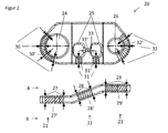
- FIG. 2 an embodiment of an exemplary workpiece 20 is shown in a side view and in a plan view.
- the possible gripping positions of a gripper on the workpiece to be clarified are caused on the one hand by the geometry of the workpiece, and on the other by the design of the gripping element.
- FIG. 2 illustrated exemplary workpiece 20 has an elongated, flat shape with a left region 21, a central region 22 and a right region 23, which are configured in just and are connected via bends with each other. Furthermore, the workpiece has openings 24 to 26.
- the workpiece can now be gripped laterally or frontally via a finger gripper, which engages on the top and bottom of the workpiece in the region of the planar regions 21 to 23.
- these gripping positions 27 to 29 are not single gripping points, but gripping areas 27 'to 29', which extend around or between the permissible gripping points.
- the workpiece can be gripped by one of the gripper fingers of the gripper engages in the openings 24 to 26 of the workpiece, while the other engages the outer periphery.
- a gripping position in which both fingers pass through the apertures 24 to 26 is given with the gripping position 33 and the gripping area 33 ', respectively.
- the device according to the present invention is now designed such that, when the workpieces are handled from the container 5, a large part or all of the gripping positions, which are possible with regard to the geometry of the workpiece and the design of the gripper, also as an allowable gripping position in the control are deposited.
- a plurality of gripping positions are available for gripping the workpieces in the container, so that generally at least one workpiece always lies in the container so that it can actually be gripped with an allowable gripping position.
- this procedure allows 100% emptying of the container.
- the at least two different, defined storage positions provided by the intermediate station ensure that a workpiece gripped in the container can actually also be deposited in a defined manner on the intermediate storage. In this case, the selection of used for storing workpiece trays of the intermediate station in dependence on the gripping position used for gripping takes place.
- an association between the possible gripping positions of the workpiece during the grip in the container and the usable workpiece trays is stored in the control unit 3 on the intermediate station.
- this can be done in the form of a table, which assigns the workpiece positions corresponding to the gripping positions 27 to 32 and 30 to 32.
- the table is preferably stored in the first control component 2, and in particular in the passive part of this control component.
- the permissible gripping positions not necessarily to singular points, so that can not be excluded only by the assignment of the permissible gripping areas to certain workpiece trays that it still comes to collisions.
- the permissible gripping regions can be defined in particular via an off-set with respect to an allowable gripping position arranged within the region.
- the exemplary embodiment of the controller 3 therefore comprises a collision viewing module.
- This contains a 3-D model of the gripper, the workpiece and the clipboard, and calculates based on the concrete gripping position, d. H. in the exemplary embodiment based on the off-set of a predetermined gripping point, whether a collision-free placement of the workpiece on the this clip point associated with clipboard is possible.
- the workpiece is again placed in the container 5 and grasped again.
- the collision viewing according to the invention is preferably carried out live while the gripped workpiece is removed from the container via the gripper 7. This saves cycle time since the calculation does not have to be present before gripping.
- the intermediate station may have a sensor, not shown, which determines the gripping position of the gripper after gripping in the container 5 and before depositing on the intermediate position.
- a sensor determines the gripping position of the gripper after gripping in the container 5 and before depositing on the intermediate position.
- a change in the intended gripping in the container gripping position can be detected, which, for example, may be caused by slipping of the workpiece on the gripper.
- the workpiece placement on the intermediate station and / or the collision check are selected on the basis of the gripping position determined by the sensor. This would allow the collision view to be performed with even more accurate data.
- a sensor for example, a camera or a laser distance sensor can be used.
- the workpieces received on the gripper are moved into the region of the sensor to determine the exact position of the workpiece on the gripper.
- a sensor arranged on the gripper could also be used for this purpose or a sensor between container and clipboard can be arranged.
- the functions that the intermediate station must provide are defined. These are on the one hand the number and structure of the workpiece shelves, on the other hand functions for providing other gripping points for the workpieces on the intermediate station, such as the turning, pivoting, delivery of workpieces and / or workpiece trays.
- preferred gripping points are defined, in particular on the basis of the mechanical properties such as stability in the gripper, and / or the cycle time and the situation on the intermediate station. These gripping points are preferably used when the handle in the container. If the workpiece can be gripped over a preferred gripping point, it may be possible to bypass the intermediate station.
- the category of gripping points influences the design of the grippers and the design of the intermediate station
- a buffer function of the intermediate station can be made available.
- several intermediate stations, as shown in the drawings, can be combined to form a larger intermediate station.
- the cycle times can be done, since depending on the available gripping positions on a workpiece and predefined storage positions, the cycle time of the handle can vary in the container and the recording and positioning can be faster in a predefined Endalage, as the container removal , The cycle times must then be coordinated with each other and the present invention configured intermediate station can act as a buffer and prevent a stoppage of the system or a waiting of the individual operations on each other.
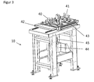
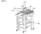
- a first embodiment of an intermediate station according to the invention is in Fig. 3 and 4 shown in more detail.
- the exemplary embodiment has two different nests 40 and 41 on the one hand. These are used to pick up workpieces that have been gripped from the top or bottom.
- the two different nests are required because the top A of the workpiece is designed differently than the bottom B of the workpiece. Depending on whether the workpiece has now been gripped by its upper side A or its lower side B, it is therefore deposited either in the nest 40 or 41.
- the intermediate station on two pins 45 on which a workpiece can be stored.
- the pins 45 engage with their tips 47 in the openings of the workpiece and thus also allow a precise placement of the workpieces.
- the two pins 45 by an adjusting element 46, in the embodiment, a hydraulic or pneumatic cylinder, in height against each other adjustable.
- an adjusting element 46 in the embodiment, a hydraulic or pneumatic cylinder, in height against each other adjustable.
- Workpiece shelf shown allows the placing of the workpieces in 4 defined storage positions.
- the assignment to the gripping areas takes place in such a way that, depending on whether the workpieces are gripped from above or below or laterally or frontally, a deposit takes place in the nests or on the pins.
- the selection then takes place between the two nests or the two workpiece trays provided by the pins.
- the clipboard according to the invention is designed so that by moving the storage elements a change in the storage position of a stored on the clipboard workpiece is possible. This ensures that the stored on the clipboard workpieces can be used with a smaller number of permissible gripping positions of the intermediate station, and preferably with only one or two permissible gripping positions.
- the pins 45 and the nests 40 are designed so that the pins can be pushed through a travel arrangement 44 through the bottom side of the nests, and so can raise a stored in the nest workpiece.
- the removal of the workpieces from the intermediate station always takes place in the position placed on the pins, since this allows an even greater accuracy to be achieved than in the positioning in the nests.
- each of the two nests 40 and 41 are driven over the pins 45.
- the nests 40 and 41 have lateral abutment areas, over which the workpieces are guided in laying in the nests in a fixed position.
- the bottom portion of the nests is recessed so that the pins 45 can be passed therethrough.
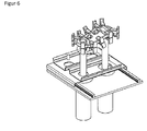
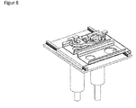
- FIG. 5 is another, slightly modified embodiment of the workpiece trays used on the intermediate station shown in three different storage positions.
- the three different storage positions are enlarged once again in Fig. 6 . 7 and 8th shown.
- two nests 40 and 41 are again provided, which are arranged on a carriage 42 and can be moved by means of a travel arrangement 43.
- the two nests 41 and 42 each have lateral boundary rails 49 which laterally define the position of the workpieces.
- a storage point 48 is provided in each case, which is arranged in the nest 40 on the left, in the nest 41 on the right side, and on which in the storage on the A side in nest 41 or B side in nest 40 increases arranged part of the workpiece is stored.
- the openings 50 can be seen in the bottom of the nests through which the pins 45 pass.
- the pins 45 are each mounted in a guide 44, and in this separately adjustable in height to raise the stored in the nests 40 and 41 workpieces can. To change the relative height of the tips 47 of the pins to each other, the two pins 45 are raised differently wide.
- Fig. 5 In Fig. 5 and enlarged in Fig. 6 to 8 also, the gripper 60 is shown with the gripping fingers 61, with the respective possible gripping positions on the workpiece.
- a workpiece which has been gripped from above or below, is placed in a nest, depending on the side from which it has been gripped, in the nest 40 or 41.
- the removal of the workpieces is always in the left in Fig. 5 or in Fig. 6 shown, placed on the pins position.
- the workpieces stored in the nests are raised above the pins.
- the respective nest drives over the pins, and the pins are driven through the openings 50 upwards.
- the left or right pin is lifted higher.
- the removal of the workpieces from the intermediate station takes place with at least two permissible gripping points which correspond to the two different orientations of the workpieces (side A or B above). As in Fig. 5 on the left, the workpiece is gripped sideways. From these two different gripping positions, however, a placement of the workpieces in the target tray is possible only on the movement of the picking gripper.
Landscapes
- Engineering & Computer Science (AREA)
- Robotics (AREA)
- Mechanical Engineering (AREA)
- Health & Medical Sciences (AREA)
- General Health & Medical Sciences (AREA)
- Orthopedic Medicine & Surgery (AREA)
- Manipulator (AREA)
- Specific Conveyance Elements (AREA)
- De-Stacking Of Articles (AREA)
Abstract
Die Erfindung betrifft eine Vorrichtung zum automatisierten Entnehmen von in einem Behälter angeordneten Werkstücken, mit einer Objekterkennungseinrichtung zum Erfassen der Werkstücke und einem Greifer zum Greifen und Entnehmen der Werkstücke aus dem Behälter, einer Steuerung zur Auswertung der Daten der Objekterkennungseinrichtung, zur Pfadplanung und zur Ansteuerung des Greifers, und einer Zwischenstation, auf welcher der Greifer die Werkstücke nach dem Entnehmen aus dem Behälter ablegt, wobei die Werkstücke von einem Greifer von der Zwischenstation aufgenommen und in einer Ziel-Ablage abgelegt werden, wobei die Zwischenstation mindestens zwei unterschiedliche Werkstück-Ablagen zum Ablegen des Werkstücks in mindestens zwei unterschiedlichen, definierten Ablagepositionen aufweist.The invention relates to a device for the automated removal of arranged in a container workpieces, with an object detection device for detecting the workpieces and a gripper for gripping and removing the workpieces from the container, a controller for evaluating the data of the object recognition device for path planning and for controlling the Gripper, and an intermediate station on which the gripper deposits the workpieces after removal from the container, wherein the workpieces are picked up by a gripper from the intermediate station and stored in a destination tray, the intermediate station at least two different workpiece trays for storing of the workpiece in at least two different, defined storage positions.
Description
Die vorliegende Erfindung betrifft eine Vorrichtung zum automatisierten Entnehmen von in einem Behälter angeordneten Werkstücken. Insbesondere dient die erfindungsgemäße Vorrichtung dabei dazu, ungeordnet in einem Behälter angeordnete Werkstücke zu entnehmen und in einer Ziel-Ablage abzulegen.The present invention relates to a device for the automated removal of workpieces arranged in a container. In particular, the device according to the invention thereby serves to remove workpieces arranged in a container in a random manner and deposit them in a destination tray.
Die Vorrichtung umfasst dabei eine Objekterkennungseinrichtung zum Erfassen der Werkstücke und einen Greifer zum Greifen und Entnehmen der Werkstücke aus dem Behälter, eine Steuerung zur Auswertung der Daten der Objekterkennungseinrichtung, zur Pfadplanung und zur Ansteuerung des Greifers, und eine Zwischenstation, auf welcher der Greifer die Werkstücke nach dem Entnehmen aus dem Behälter ablegt. Weiterhin ist dabei vorgesehen, dass die Werkstücke von einem Greifer von der Zwischenstation aufgenommen und in einer Ziel-Ablage abgelegt werden. Insbesondere kann es sich bei der Ziel-Ablage um eine Werkstück-Ablage einer Transport-, Bearbeitungs- und/oder Montageeinreichung handeln.The apparatus comprises an object recognition device for detecting the workpieces and a gripper for gripping and removing the workpieces from the container, a controller for evaluating the data of the object recognition device, for path planning and for driving the gripper, and an intermediate station, on which the gripper the workpieces after removal from the container deposits. Furthermore, it is provided that the workpieces are picked up by a gripper from the intermediate station and stored in a destination tray. In particular, the destination tray can be a workpiece tray of a transport, processing and / or assembly submission.
Eine solche Vorrichtung ist beispielsweise aus der
Weiterhin ist aus der
Um jedoch alle Werkstücke aus dem Behälter mittels des Greifers entnehmen zu können, muss eine möglichst hohe und vorzugsweise uneingeschränkte Anzahl von möglichen Greifpositionen des Greifers am Werkstück zugelassen werden, um so möglichst viele Freiheitsgrade bezüglich der Bewegung des Greifers zur Verfügung zu haben. Nur so können auch noch kritische Teile im Behälter gegriffen werden. Denn durch die spezifische Lage eines Werkstücks innerhalb des Behälters steht ohnehin üblicherweise nur eine sehr eingeschränkte Untergruppe aller theoretisch zulässigen Greifpositionen zur Verfügung.However, in order to be able to remove all workpieces from the container by means of the gripper, the highest possible and preferably unrestricted number of possible gripping positions of the gripper on the workpiece must be allowed in order to have as many degrees of freedom as possible with respect to the movement of the gripper. Only then can even critical parts in the container be grasped. Because of the specific position of a workpiece within the container is usually only a very limited subset of all theoretically permissible gripping positions available.
Allerdings erlaubt - bedingt durch die Werkstückkontur und / oder die Kontur des Greifers - nicht jede Greifposition, welche beim Greifen im Behälter eingesetzt werden könnte, ein positionsgenaues Ablegen des Werkstücks an einer vordefinierten Ziel-Ablage. Werden jedoch nur jene Greifpositionen zum Entnehmen aus dem Behälter zugelassen, welche eine solche positionsgenaue und vordefinierte Ablage des Werkstücks erlauben, wird hierdurch die 100 %ige Entleerung des Behälters beeinträchtigt oder sogar verhindert.However, due to the workpiece contour and / or the contour of the gripper, not every gripping position that could be used when gripping in the container permits accurate positioning of the workpiece on a predefined target tray. However, if only those gripping positions for removal from the container are allowed, which allow such a positionally accurate and predefined storage of the workpiece, thereby the 100% emptying of the container is affected or even prevented.
Aufgabe der vorliegenden Erfindung ist es daher, eine Vorrichtung zum automatisierten Entnehmen von in einem Behälter angeordneten Werkstücken zur Verfügung zu stellen, welche zum einen eine maximale Entleerung des Behälters und zum anderen eine positionsgenaue, vororientierte und/oder flexible Ablage des Werkstücks erlaubt.Object of the present invention is therefore to provide a device for the automated removal of arranged in a container workpieces available, which allows for a maximum emptying of the container and on the other hand a positionally accurate, pre-oriented and / or flexible storage of the workpiece.
Diese Aufgabe wird erfindungsgemäß durch eine Vorrichtung gemäß Anspruch 1 gelöst.This object is achieved by a device according to
Die erfindungsgemäße Vorrichtung zum automatisierten Entnehmen von in einem Behälter angeordneten Werkstücken umfasst eine Objekterkennungseinrichtung zum Erfassen der Werkstücke und einen Greifer zum Greifen und Entnehmen der Werkstücke aus dem Behälter. Weiterhin ist eine Steuerung zur Auswertung der Daten der Objekterkennungseinrichtung, zur Pfadplanung und zur Ansteuerung des Greifers vorgesehen, sowie eine Zwischenstation, auf welcher der Greifer die Werkstücke nach dem Entnehmen aus dem Behälter ablegt. Dabei ist die Steuerung der Vorrichtung so ausgestaltet, dass die Werkstücke von einem Greifer automatisiert von der Zwischenstation aufgenommen und in einer Ziel-Ablage abgelegt werden.. Insbesondere kann es sich bei der Ziel-Ablage um eine Werkstück-Ablage einer Transport-, Bearbeitungs- und/oder Montageeinreichung handeln. Erfindungsgemäß weist die Zwischenstation dabei mindestens zwei unterschiedliche Werkstückablagen zum Ablegen der Werkstücke in mindestens zwei unterschiedlichen, definierten Ablagepositionen auf. Bevorzugt wird die Vorrichtung gemäß der vorliegenden Erfindung dabei zum Entnehmen von ungeordnet in dem Behälter angeordneten Werkstücken eingesetzt.The device according to the invention for the automated removal of workpieces arranged in a container comprises an object recognition device for detecting the workpieces and a gripper for gripping and removing the workpieces from the container. Furthermore, a controller for evaluating the data of the object recognition device, for path planning and for driving the gripper is provided, as well as an intermediate station, on which the gripper stores the workpieces after removal from the container. The control of the device is designed so that the workpieces are automatically taken up by a gripper of the intermediate station and stored in a destination tray .. In particular, it may be at the destination tray to a workpiece tray a transport, processing and / or assembly submission. According to the invention, the intermediate station has at least two different workpiece trays for depositing the workpieces in at least two different, defined storage positions. Preferably, the device according to the present invention is thereby used for removing workpieces disposed in the container in a random manner.
Anders als gemäß dem Stand der Technik in der
In einer möglichen Ausführungsform befindet sich dabei zu jedem Zeitpunkt maximal ein Werkstück auf der Zwischenstation.In one possible embodiment, at most each time a workpiece is located on the intermediate station.
In einer alternativen Ausführungsform kann die Zwischenstation als Puffer dienen, indem mehr als ein Werkstück auf der Zwischenablage abgelegt wird. Ein solches Vorgehen ist insbesondere bei der Verwendung von zwei Greifern von Vorteil, um Unterschiede in den Taktzeiten auszugleichen. Die Taktzeiten für den Griff im Behälter und das Ablegen auf der Zwischenstation können dabei je nach Greifpunkt an dem Werkstück im Behälter und der Position des Werkstücks im Behälter erheblich variieren. Insbesondere kann dabei je nach dem gerade zu greifenden Werkstück die Aufnahme von der Zwischenstation und Ablage in der Ziel-Ablage langsamer als der Griff im Behälter und die Ablage auf der Zwischenstation erfolgen, oder umgekehrt. Insbesondere können dabei in Phasen, in welchen die Taktzeit für den Griff aus dem Behälter kleiner ist als die Taktzeit für das Ablegen auf der Ziel-Ablage mehr als ein Werkstück auf der Zwischenstation abgelegt werden, welche in Phasen, in welchen die Taktzeit für den Griff aus dem Behälter größer ist als die Taktzeit für das Ablegen auf der Ziel-Ablage wieder abgenommen werden.In an alternative embodiment, the intermediate station may serve as a buffer by depositing more than one workpiece on the clipboard. Such an approach is particularly advantageous when using two grippers to compensate for differences in cycle times. The cycle times for the handle in the container and the depositing on the intermediate station can vary considerably depending on the gripping point on the workpiece in the container and the position of the workpiece in the container. In particular, depending on the workpiece to be gripped, the recording of the intermediate station and filing in the destination filing may take place more slowly than the gripping in the receptacle and the filing on the intermediate station, or vice versa. In particular, in phases in which the cycle time for the handle from the container is smaller than the cycle time for depositing on the destination tray more than a workpiece can be stored on the intermediate station, which in phases in which the cycle time for the handle out of the container is greater than the tact time for the deposit on the destination tray to be removed again.
Vorteilhafterweise weist die Zwischenstation hierfür mehr Werkstückablagen auf, als für das Ablegen eines Werkstückes mit beliebigen Greifpunkten notwendig wären. Insbesondere kann die Zwischenstation dabei von jeder Art von Werkstückablage mindestens zwei Exemplare umfassen. Die Zwischenstation kann dabei auch mindestens separate Untereinheiten aufweisen, von welchen jede jeweils auch für sich genommen als Zwischenstation gemäß der vorliegenden Erfindung für ein Werkstück dienen könnte.Advantageously, the intermediate station for this more workpiece trays, as would be necessary for the deposition of a workpiece with any gripping points. In particular, the intermediate station can comprise at least two copies of each type of workpiece deposit. The intermediate station can also have at least separate subunits, each of which, taken separately, could serve as a temporary station according to the present invention for a workpiece.
Vorteilhafterweise erfolgt das Greifen der Werkstücke im Behälter dabei mit einer Mehrzahl von unterschiedlichen zulässigen Greifpositionen. Bevorzugt werden dabei alle Greifpositionen, mit welchen der Greifer ein Werkstück greifen kann, zugelassen. Hierdurch wird die Entleerung verbessert. Bevorzugt weist dabei die Zwischenstation so viele unterschiedliche Werkstückablagen auf, dass für im wesentlichen jede zulässige Greifposition beim Greifen der Werkstücke im Behälter mindestens eine Werkstückablage zur Verfügung steht, an welcher das Werkstück auf der Zwischenstation abgelegt werden kann.Advantageously, the gripping of the workpieces in the container takes place with a plurality of different permissible gripping positions. In this case, all gripping positions with which the gripper can grip a workpiece are preferably permitted. As a result, the emptying is improved. In this case, the intermediate station preferably has so many different workpiece trays that at least one workpiece tray is available for substantially every permissible gripping position when gripping the workpieces in the container, at which the workpiece can be deposited on the intermediate station.
Bevorzugt erfolgt die Auswahl der zum Ablegen genutzten Werkstückablage der Zwischenstation dabei auf Grundlage der Greifposition, mit welcher das Werkstück aus dem Behälter entnommen wird oder wurde.Preferably, the selection of the used for depositing the workpiece storage of the intermediate station takes place on the basis of the gripping position, with which the workpiece is removed from the container or was.
In einer möglichen Ausführungsform wird dabei die Werkstückablage, in welcher das Werkstück auf der Zwischenstation abgelegt wird, bereits vor bzw. während des Greifens eines Werkstücks im Behälter ermittelt, sodass die zur Verfügung stehenden Werkstückablagen bereits bei der Auswahl der Greifposition zum Greifen im Behälter einfließen können.In one possible embodiment, the workpiece deposit, in which the workpiece is deposited on the intermediate station, is already determined before or during the gripping of a workpiece in the container, so that the available workpiece trays can already flow into the container during the selection of the gripping position for gripping ,
In einer bevorzugten Ausführungsform erfolgt die Auswahl der zum Ablegen genutzten Werkstückablage dagegen erst dann, wenn ein Griff des Werkstücks im Behälter erfolgt ist. Hierdurch kann die Zeit, welche für das Entnehmen des Werkstücks aus dem Behälter benötigt wird, zu der Ermittlung der zum Ablegen nutzbaren Werkstückablagen und zur Auswahl der Werkstückablage genutzt werden.In a preferred embodiment, on the other hand, the selection of the workpiece deposit used for depositing, on the other hand, takes place only when a grip of the workpiece in the container has taken place. As a result, the time required for the removal of the workpiece from the container can be used to determine the workpieces usable for depositing and to select the workpiece tray.
In einer möglichen Ausführungsform der vorliegenden Erfindung erfolgt die Auswahl der Werkstückablage dabei aufgrund einer vordefinierten Zuordnung zwischen bestimmten Greifpositionen und bestimmten Werkstückablagen. Insbesondere kann dabei am Werkstück eine Mehrzahl von vorbestimmten Greifpositionen definiert sein, in welchen die Werkstücke gegriffen werden können. Diese sind bevorzugt einer oder mehreren Werkstückablagen zugeordnet, welche im Allgemeinen ein in einer solchen Greifposition gegriffenes Werkstück aufnehmen können. Insbesondere kann die Auswahl dabei über eine Abfrage einer in der Steuerung hinterlegten Zuordnungstabelle zwischen den Greifpositionen und den Werkstückablagen erfolgen.In one possible embodiment of the present invention, the selection of the workpiece placement takes place on the basis of a predefined association between specific gripping positions and specific workpiece trays. In particular, a plurality of predetermined gripping positions can be defined on the workpiece, in which the workpieces can be gripped. These are preferably associated with one or more workpiece trays, which are generally in can pick up gripped workpiece such a gripping position. In particular, the selection can take place via a query of a stored in the control mapping between the gripping positions and the workpiece trays.
Erfindungsgemäß kann weiterhin vorgesehen sein, dass das Greifen der Werkstücke im Behälter mit einer Mehrzahl von unterschiedlichen zulässigen Greifpunkten erfolgt. Solche zulässigen Greifpunkte können dann wie oben beschrieben bestimmten Werkstückablagen zugeordnet sein.According to the invention, it may further be provided that the gripping of the workpieces in the container takes place with a plurality of different permissible gripping points. Such permissible gripping points can then be assigned to specific workpiece trays as described above.
Weiterhin ist es möglich, dass das Greifen der Werkstücke im Behälter auch in sich um solche Greifpunkte erstreckenden zulässigen Greifbereichen erfolgen kann. Insbesondere kann dabei beim Greifen ein gewisser Off-Set gegenüber gewissen Greifpunkten erlaubt sein.Furthermore, it is possible that the gripping of the workpieces in the container can also take place in such permissible gripping areas extending around such gripping points. In particular, while gripping a certain off-set against certain gripping points may be allowed.
Auch hier kann zur Auswahl der Werkstückablage eine vordefinierte Zuordnung zwischen zulässigen Greifbereichen und Werkstückablagen genutzt werden.Again, a predefined assignment between allowable gripping areas and workpiece trays can be used to select the workpiece tray.
Alternativ oder zusätzlich kann jedoch auch eine Kollisionsprüfung erfolgen, bei welcher anhand eines geometrischen Modells überprüft wird, ob ein kollisionsfreies Ablegen eines in einer spezifischen Greifposition gegriffenen Werkstücks auf einer Werkstückablage der Zwischenstation möglich ist. Die Kollisionsprüfung kann dabei vor dem Greifen des Werkstücks im Behälter erfolgen. So wird vermieden, dass ein gegriffenes Werkstück nicht auf der Zwischenstation abgelegt werden kann und wieder in den Behälter zurück abgelegt werden muss. In einer alternativen Ausführungsform erfolgt diese Kollisionsprüfung dagegen nach dem Greifen des Werkstücks im Behälter. Hierdurch kann die Zeit, in welcher das Werkstück aus dem Behälter entnommen wird, zur Durchführung der Kollisionsprüfung genutzt werden. In einer weiteren bevorzugten Ausführungsform kann die Kollisionsprüfung parallel zum Greifprozess stattfinden um Zykluszeiten zu reduzieren.Alternatively or additionally, however, a collision check can also take place in which it is checked on the basis of a geometric model whether collision-free depositing of a workpiece gripped in a specific gripping position on a workpiece deposit of the intermediate station is possible. The collision check can be done before grasping the workpiece in the container. This avoids that a gripped workpiece can not be stored on the intermediate station and must be put back into the container. In an alternative embodiment, however, this collision test is carried out after grasping the workpiece in the container. This allows the time in which the workpiece is removed from the container to be used to perform the collision check. In a further preferred embodiment, the collision check can take place parallel to the gripping process in order to reduce cycle times.
In einer besonders bevorzugten Ausführungsform erfolgt dabei zunächst eine Auswahl der Werkstückablagen, auf welchen eine Ablage potentiell möglich ist, durch eine vordefinierte Zuordnung zwischen zulässigen Greifpunkten bzw. zulässigen Greifbereichen und den Werkstückablagen. Dem ist bevorzugt eine Kollisionsprüfung nachgeschaltet, welche überprüft, ob tatsächlich ein kollisionsfreies Ablegen auf wenigstens einer der Werkstückablagen möglich ist. Ist dies nicht der Fall, so wird das Werkstück bevorzugt nicht gegriffen oder wieder im Behälter abgelegt.In a particularly preferred embodiment, a selection of the workpiece trays on which a deposit is potentially possible initially takes place by means of a predefined association between permissible gripping points or permissible gripping areas and the workpiece trays. This is preferably followed by a collision check, which checks whether a collision-free depositing on at least one of the workpiece trays is actually possible. If this is not the case, the workpiece is preferably not grasped or placed back in the container.
Bei der Kollisionsprüfung kann dabei ein geometrisches Modell sowohl der Zwischenstation, als auch des Greifers und des Werkstücks eingesetzt werden, um Kollisionen beim Ablegen eines Werkstücks auf der Zwischenstation sicher zu erkennen.In the collision test, a geometric model of both the intermediate station, as well as the gripper and the workpiece can be used to reliably detect collisions when placing a workpiece on the intermediate station.
Weiterhin kann ein Sensor vorgesehen sein, welcher die Greifposition des Greifers nach dem Greifen im Behälter und vor dem Ablegen auf der Zwischenposition ermittelt. Hierdurch kann eine Veränderung in der beim Greifen im Behälter beabsichtigten Greifposition erkannt werden, welche bspw. durch ein Verrutschen des Werkstücks am Greifer bedingt sein kann. Bevorzugt erfolgt die Auswahl der Werkstückablage auf der Zwischenstation und/oder die Kollisionsprüfung auf Grundlage der vom Sensor ermittelten Greifposition. Als Sensor kann beispielsweise eine Kamera oder ein Laserabstandssensor eingesetzt werden. Der Sensor ist bevorzugt an der Zwischenstation angeordnet, wobei der Greifer das Werkstück nach dem Herausnehmen aus dem Behälter zunächst in den Bereich des Sensors bewegt, bevor ein Ablegen auf der Zwischenstation erfolgt. Weiterhin bevorzugt kann der Sensor zwischen dem Behälter und der Zwischenstation angeordnet sein.Furthermore, a sensor may be provided which determines the gripping position of the gripper after gripping in the container and before depositing on the intermediate position. As a result, a change in the intended gripping in the container gripping position can be detected, which, for example, may be caused by slipping of the workpiece on the gripper. The selection of the workpiece deposit on the intermediate station and / or the collision check preferably takes place on the basis of the gripping position determined by the sensor. As a sensor, for example, a camera or a laser distance sensor can be used. The sensor is preferably arranged at the intermediate station, wherein the gripper first moves the workpiece into the region of the sensor after it has been removed from the container before it is deposited on the intermediate station. Further preferably, the sensor can be arranged between the container and the intermediate station.
In einer möglichen Ausführungsform der vorliegenden Erfindung erfolgt in Abhängigkeit von der Greifposition, mit welcher das Werkstück im Behälter gegriffen wurde, eine Entscheidung, ob das Werkstück zunächst auf der Zwischenstation abgelegt wird, um von dort nochmals aufgenommen zu werden, oder direkt an der ZielAblage abgelegt wird. Dabei können einige Greifpunkte vorgesehen sein, bei welchen ein direktes Ablegen auf der Ziel-Ablage erfolgt, und andere Greifpunkte, welche ein Ablegen auf der Zwischenstation notwendig machen. Die Entscheidung kann dabei in einer möglichen Ausführungsform erfolgen, nachdem die Greifposition über einen Sensor ermittelt wurde.In one possible embodiment of the present invention, depending on the gripping position with which the workpiece was grasped in the container, a decision is made as to whether the workpiece is first deposited on the intermediate station in order to be resumed therefrom, or deposited directly on the target tray becomes. In this case, some gripping points may be provided, in which a direct deposition takes place on the target tray, and other gripping points, which make a deposit on the waypoint necessary. The decision can be made in one possible embodiment, after the gripping position has been determined via a sensor.
Weiterhin können bestimmte Greifpunkte beim Griff im Behälter bevorzugt ausgewählt werden, insbesondere solche, welche ein direktes Ablegen auf einer Ziel-Ablage oder eine geringere Zykluszeit beim Ablegen und Wiederaufnehmen auf der Zwischenablage benötigen als andere Greifpunkte, und/oder Greifpunkte, welche ein sichereres Greifen ermöglichen. Gibt es daher im Behälter mehrere Werkstücke, welche gegriffen werden könnten, erfolgt die Auswahl des tatsächlich gegriffenen Werkstücks vorteilhafterweise anhand der jeweils zur Verfügung stehenden Greifpunkte.Furthermore, certain gripping points can be preferably selected when gripping the container, in particular those which require direct placement on a destination tray or a shorter cycle time when placing and resuming on the clipboard than other gripping points, and / or gripping points which allow safer gripping , If, therefore, there are several workpieces in the container which could be gripped, the selection of the workpiece actually gripped is advantageously carried out on the basis of the respectively available gripping points.
Gemäß der vorliegenden Erfindung erfolgt das Aufnehmen des Werkstücks von der Zwischenstation bevorzugt mit weniger zulässigen Greifpositionen als das Greifen im Behälter. Die Zwischenstation sorgt so für eine Reduktion der zulässigen Greifpositionen. Bevorzugt kann das Werkstück dabei von der Zwischenstation immer mit einer Greifposition gegriffen werden, welche ein eindeutiges vordefiniertes Ablegen in einer Ziel-Ablage ermöglicht. Bevorzugt ermöglicht das Greifen von der Zwischenstation dabei das Ablegen aller Werkstücke in einer einzigen, vordefinierten Position und / oder Ausrichtung und / oder an einer einzigen Art von Ziel-Ablage.According to the present invention, the picking up of the workpiece from the intermediate station preferably takes place with fewer permissible gripping positions than the gripping in the container. The intermediate station thus ensures a reduction of the permissible gripping positions. Preferably, the workpiece can be gripped by the intermediate station always with a gripping position, which allows a clear predefined storage in a destination tray. Preferably, the gripping of the intermediate station thereby allows the depositing of all workpieces in a single, predefined position and / or orientation and / or on a single type of target tray.
Bevorzugt erfolgt das Aufnehmen des Werkstücks von der Zwischenstation dabei mit nur einer einzigen oder mit den Greifpositionen die ein endgültiges Ablegen in der Endposition zulassen
In einer möglichen ersten Ausführungsform der vorliegenden Erfindung wird derselbe Greifer zum Greifen der Werkstücke aus dem Behälter und zum Aufnehmen von der Zwischenablage eingesetzt.Preferably, the picking up of the workpiece from the intermediate station takes place here with only one or with the gripping positions which permit a definitive depositing in the end position
In a possible first embodiment of the present invention, the same gripper is used to grasp the workpieces from the container and to pick them up from the clipboard.
Alternativ werden zwei separate Greifer zum Greifen der Werkstücke aus dem Behälter und zum Aufnehmen von der Zwischenablage eingesetzt. Der Einsatz von zwei separaten Greifern erhöht dabei die Taktrate, da der erste Greifer schon wieder zum Greifen eines Werkstücks aus dem Behälter eingesetzt wird, während der zweite Greifer ein Werkstück von der Zwischenablage aufnimmt und an der Ziel-Ablage ablegt. Bevorzugt werden die beiden separaten Greifer dabei durch separate Greifarme bewegt.Alternatively, two separate grippers are used to grasp the workpieces from the container and to pick them up from the clipboard. The use of two separate grippers increase the clock rate, since the first gripper is already used again for gripping a workpiece from the container, while the second gripper picks up a workpiece from the clipboard and deposits on the destination tray. Preferably, the two separate grippers are moved by separate gripping arms.
Erfindungsgemäß kann es sich bei dem Greifer zum Greifen der Werkstücke im Behälter und / oder zum Aufnehmen von der Zwischenablage um einen magnetischen, pneumatischen oder mechanischen Greifer, ggf. auch eine Kombination aus diesen Möglichkeiten, besonders bevorzugt um einen mechanischen Greifer handeln. Ein solcher mechanischer Greifer erlaubt eine höhere Greifgenauigkeit. Insbesondere kann es sich dabei um einen Fingergreifer oder einen Backengreifer handeln. Bevorzugt ist der Greifer dabei gekröpft am Greifarm oder einer Greifarmverlängerung angeordnet. Insbesondere kann der Greifer dabei so ausgestaltet sein, wie dies aus der
Ist die Position der Werkstücke im Behälter vorab bekannt, beispielsweise weil diese geordnet im Behälter angeordnet sind, so kann die Objekterkennungseinrichtung gegebenenfalls auch nur anhand solcher vorbekannten Positionsdaten erfolgen.If the position of the workpieces in the container is known in advance, for example because they are arranged in an orderly manner in the container, then the object recognition device can optionally also be made only on the basis of such previously known position data.
Das Erfassen der Werkstücke umfasst jedoch vorteilhafterweise eine Datenerhebung durch einen Messvorgang. Dann erfolgt durch Auswertung der Daten eine Identifizierung der einzelnen Werkstücke im Erfassungsbereich, aus welchen ein zum Greifen geeignetes Werkstück ausgewählt wird. Dabei werden bevorzugt die möglichen Greifpositionen, mit welchen ein solches Werkstück gegriffen werden kann, ermittelt und eine zum Greifen geeignete Greifposition ausgewählt. Auf Grundlage der Positionsdaten des Werkstücks sowie der ausgewählten Greifposition wird dann die Bewegung des Greifers bzw. des diesen bewegenden Greifarmes geplant. Dabei kann eine Kollisionsprüfung durchgeführt werden, sodass ein Bewegungsablauf gewählt wird, bei welchem der Greifer bzw. der Greifarm nicht mit Störkanten wie beispielsweise den anderen Werkstücken und / oder den Seitenwänden des Behälters kollidiert. Anhand der so berechneten Daten wird dann der Greifer bzw. der Greifarm angesteuert.However, the detection of the workpieces advantageously comprises a data collection by a measuring operation. Then, by evaluating the data, an identification of the individual workpieces in the detection area, from which a suitable for gripping workpiece is selected. In this case, the possible gripping positions with which such a workpiece can be gripped are preferably determined, and a gripping position suitable for gripping is selected. On the basis of the position data of the workpiece and the selected gripping position, the movement of the gripper or of the gripper arm which moves it is then planned. In this case, a collision check can be carried out, so that a movement sequence is selected in which the gripper or the gripper arm does not collide with interfering edges, such as the other workpieces and / or the side walls of the container. On the basis of the data thus calculated, the gripper or the gripping arm is driven.
Als Objekterfassungseinrichtung kommen dabei insbesondere optische Sensoren zum Einsatz, wobei insbesondere Laser- und / oder Bildsensoren zum Einsatz kommen können. Die Sensoren können dabei zweidimensional, zwei-einhalb-dimensional oder dreidimensional arbeiten. Besonders bevorzugt kommt dabei ein 3-D-Laserscanner zum Einsatz.In particular, optical sensors are used as the object detection device, laser and / or image sensors in particular being able to be used. The sensors can work two-dimensionally, two-and-a-half-dimensionally or three-dimensionally. Particularly preferred is a 3-D laser scanner is used.
Die Objekterkennungseinrichtung zum Erfassen der Werkstücke im Behälter ist dabei bevorzugt in ihrer Messposition oberhalb des Behälters angeordnet.The object recognition device for detecting the workpieces in the container is preferably arranged in its measuring position above the container.
Das Erfassen der Werkstücke, die Bahnplanung und das Greifen und Entnehmen der Werkstücke aus dem Behälter kann dabei insbesondere so erfolgen, wie dies aus der
In einer möglichen Ausführungsform der vorliegenden Erfindung kann auf der Zwischenstation eine nochmalige Objekterkennung des Werkstücks erfolgen, sodass das Aufnehmen des Werkstücks von der Zwischenstation auf Grundlage dieser nochmaligen Objekterkennung erfolgt.In one possible embodiment of the present invention, a repeated object recognition of the workpiece can take place on the intermediate station, so that the workpiece is picked up by the intermediate station on the basis of this repeated object recognition.
Gemäß einer bevorzugten Ausführungsform der vorliegenden Erfindung erfolgt das Aufnehmen des Werkstücks von der Zwischenstation jedoch auf Grundlage der bekannten Position der verwendeten Werkstückablage und der bekannten Form des Werkstücks. Besonders bevorzugt erfolgt das Aufnehmen dabei ohne eine zuvorige Objekterkennung des Werkstücks auf der Zwischenstation oder zumindest mit einer weniger aufwändigen Objekterkennung als bei dem Griff im Behälter. Hierdurch kann die Zykluszeit verringert werden.However, according to a preferred embodiment of the present invention, the picking up of the workpiece from the intermediate station is based on the known position of the workpiece tray used and the known shape of the workpiece. Particularly preferably, the recording takes place without a previous object recognition of the workpiece on the intermediate station or at least with a less complex object recognition than with the handle in the container. This can reduce the cycle time.
Erfindungsgemäß kann die Zwischenablage eine Verstellanordnung umfassen, welche eine Veränderung der Position und/oder Ausrichtung eines auf der Zwischenablage abgelegten Werkstücks und/oder eines Ablageelementes erlaubt. Hierdurch kann die Position und/oder Ausrichtung des Werkstücks an der Zwischenstation nach dem Ablegen verändert werden oder ein Ablageelement vom Werkstück weggefahren werden, um einen Greifpunkt freizugeben.According to the invention, the clipboard may comprise an adjustment arrangement which permits a change in the position and / or orientation of a workpiece and / or a deposition element deposited on the clipboard. In this way, the position and / or orientation of the workpiece at the intermediate station can be changed after depositing or a storage element can be moved away from the workpiece to release a gripping point.
Die Positionsänderung des Werkstücks und/oder eines Ablageelementes erlaubt damit bevorzugt das Aufnehmen des Werkstücks mit einem Greifpunkt, welcher in der Ablageposition nicht zur Verfügung stand. Hierdurch kann ein Umgreifen auf der Zwischenstation erfolgen, d.h. das Aufnehmen mit einem anderen Greifpunkt.The change in position of the workpiece and / or a storage element thus preferably allows the picking of the workpiece with a gripping point, which was not available in the storage position. This can be done on the intermediate station embrace, i. picking up with another grip point.
Die Verstellanordnung wird dabei bevorzugt dazu eingesetzt, um das Werkstück von der Ablageposition, in welcher es auf der Zwischenstation abgelegt wurde, in eine definierte Aufnahmeposition zu bewegen. In dieser Aufnahmeposition wird das Werkstück bevorzugt gegriffen, um auf einer Ziel-Ablage abgelegt zu werden.The adjusting arrangement is preferably used to move the workpiece from the storage position in which it was stored on the intermediate station in a defined receiving position. In this picking position, the workpiece is preferably gripped to be deposited on a target tray.
Beispielsweise kann dabei ein Werkstück, welches an einer Innenkontur gegriffen abgelegt wurde, durch die Verstellanordnung in eine Aufnahmeposition bewegt werden, welche ein Greifen an einer Außenkontur erlaubt und/oder umgekehrt.For example, a workpiece which has been gripped on an inner contour can be moved by the adjusting arrangement into a receiving position which permits gripping on an outer contour and / or vice versa.
Die Verstellanordnung kann dabei eine Drehung, Verschwenkung und/oder Verschiebung des Werkstückes vornehmen. In einer möglichen Ausführung wird dabei eine Linearverschiebung des Werkstücks vorgenommen.The adjusting arrangement can make a rotation, pivoting and / or displacement of the workpiece. In one possible embodiment, a linear displacement of the workpiece is performed.
Insbesondere kann dabei vorgesehen sein, die Werkstücke in eine oder mehrere definierte Aufnahmepositionen zu verfahren. Insbesondere kann dabei vorgesehen sein, dass durch die Verstellanordnung Werkstücke, welche in unterschiedlichen Werkstückablagen abgelegt wurden, dennoch in eine identische Aufnahmeposition verfahren werden. Bevorzugt sind dabei weniger Aufnahmepositionen als Werkstückablagen vorgesehen. Insbesondere können dabei nur eine oder zwei Aufnahmepositionen vorgesehen sein.In particular, it may be provided to move the workpieces into one or more defined receiving positions. In particular, it may be provided that workpieces which have been deposited in different workpiece trays are nevertheless moved into an identical receiving position by the adjusting arrangement. Preferably, fewer receiving positions than workpiece trays are provided. In particular, only one or two receiving positions can be provided.
Bevorzugt ist die Zwischenstation dabei so ausgestaltet, dass die Position mindestens einer der Werkstückablagen kinematisch verstellbar ist. Insbesondere kann dabei mindestens ein Antrieb vorgesehen sein, über welchen die Verstellung erfolgt. Insbesondere kann die Verstellung dabei auf Grundlage der Greifposition erfolgen, mit welcher das Werkstück aus dem Behälter entnommen wird oder wurde. Insbesondere kann dabei die jeweils verwendete Werkstückablage in eine Ablage-position und / oder eine Aufnahmeposition verfahren werden. Das Verfahren der Werkstückablage kann dabei entweder vor dem Ablegen auf der Zwischenstation erfolgen, oder während oder nach dem erfolgten Ablegen.Preferably, the intermediate station is designed so that the position of at least one of the workpiece trays is kinematically adjustable. In particular, at least one drive can be provided, via which the adjustment takes place. In particular, the adjustment can take place on the basis of the gripping position with which the workpiece is removed from the container or was. In particular, the work piece tray used in each case can be moved into a storage position and / or a pickup position. The process of workpiece storage can either be done before taking off on the intermediate station, or during or after the successful drop.
Insbesondere kann das Verfahren der Werkstückablage dabei dazu eingesetzt werden, um trotz Ablegens der Werkstücke in unterschiedlichen Werkstückablagen diese in einer übereinstimmenden Ablageposition und / oder Ausrichtung ablegen zu können, und / oder um die Werkstücke trotz der Ablage in unterschiedlichen Werkstückablagen bevorzugt in nur einer Aufnahmeposition von der Zwischenstation aufnehmen zu können.In particular, the method of workpiece placement can be used to be able to store this despite placing the workpieces in different workpiece trays in a matching storage position and / or orientation, and / or the workpieces despite the filing in different workpiece trays preferably in only one receiving position of to be able to record the intermediate station.
Die Zwischenstation kann erfindungsgemäß mindestens ein kinematisch verstellbares Ablageelement aufweisen. Insbesondere kann dabei mindestens ein Antrieb vorgesehen sein, über welchen die Verstellung erfolgt. Die kinematische Verstellung des Ablageelementes kann dabei zu unterschiedlichen Zwecken eingesetzt werden:
- Beispielsweise ist es denkbar, durch ein Verstellen des Ablageelementes mindestens zwei unterschiedliche Werkstückablagen bereitzustellen. Insbesondere kann dabei durch die Verstellung eines Ablageelementes ein Ablagebereich von einer ersten zu einer zweiten Werkstückablage umgestellt werden. Bevorzugt erfolgt die Verstellung des Ablageelementes dann in Abhängigkeit von der Greifposition des Werkstücks.
- For example, it is conceivable to provide at least two different workpiece trays by adjusting the storage element. In particular, a storage area can be changed from a first to a second workpiece storage by the adjustment of a storage element. Preferably, the adjustment of the storage element then takes place in dependence on the gripping position of the workpiece.
Alternativ oder zusätzlich kann das verfahrbare Ablageelement eine Verstellanordnung zur Verfügung stellen, welche wie oben beschrieben ein Werkstück nach dem Ablegen auf der Zwischenstation in eine Aufnahmeposition verfährt.Alternatively or additionally, the movable storage element can provide an adjustment arrangement which, as described above, moves a workpiece into a receiving position after it has been deposited on the intermediate station.
Alternativ oder zusätzlich kann durch das Verfahren des Ablageelementes ein Greifpunkt am Werkstück freigegeben werden, mit welchem das Werkstück dann von der Zwischenstation abgenommen werden kann.Alternatively or additionally, a gripping point on the workpiece can be released by the method of the storage element, with which the workpiece can then be removed from the intermediate station.
Die Zwischenstation kann erfindungsgemäß mindestens ein Nest, in welches ein Werkstück hineingelegt werden kann, und mindestens einen Pin, auf welchem ein Werkstück aufgelegt werden kann, aufweisen. Insbesondere kann das Nest dabei Seitenwände und Ablagepunkte aufweisen, wobei die Seitenwände die Umfangskontur des Werkstückes zumindest teilweise umgeben. Insbesondere können die Seitenwände dabei schräg ausgerichtet sein, um so eine Zentrierung des Werkstücks im Nest zu erlauben. Der Pin ist bevorzugt so ausgestaltet, dass das Werkstück mit einer Aussparung und / oder Innenkontur auf den Pin aufgesetzt werden kann. Gegebenenfalls kann das Auflegen dabei auch auf mehrere Pins erfolgen, welche demgemäß eine Werkstückablage bilden.According to the invention, the intermediate station can have at least one nest, into which a workpiece can be placed, and at least one pin, on which a workpiece can be placed. In particular, the nest may have side walls and storage points, wherein the side walls surround the peripheral contour of the workpiece at least partially. In particular, the side walls can be aligned obliquely so as to allow a centering of the workpiece in the nest. The pin is preferably designed so that the workpiece can be placed with a recess and / or inner contour on the pin. Optionally, the laying can also be done on several pins, which thus form a workpiece tray.
Die Zwischenstation kann auch mehrere unterschiedliche Nester und/oder mehrere unterschiedliche, durch Pins gebildete Werkstück-Ablagen umfassen.The intermediate station may also comprise a plurality of different nests and / or a plurality of different workpiece trays formed by pins.
Weiterhin können mehrere identische Nester und/oder mehrere identische Pins vorgesehen sein. Hierdurch kann eine Pufferfunktion der Zwischenstation zur Verfügung gestellt werden.Furthermore, a plurality of identical nests and / or a plurality of identical pins may be provided. As a result, a buffer function of the intermediate station can be made available.
Durch den Einsatz der Zwischenstation als Puffer kann ein Optimieren der Taktzeiten erfolgen, da je nach vorhanden Greifpositionen an einem Werkstück und vordefinierten Ablagepositionen die Taktzeit des Griffs in den Behälter variieren kann und die Aufnahme und Positionierung in eine vordefinierten Endabage schneller sein kann, als die Behälterentnahme. Die Taktzeiten müssen dann aufeinander abgestimmt sein und die erfindungsgemäß ausgestaltete Zwischenstation kann hier als Puffer fungieren und einen Stillstand der Anlage oder ein Warten der einzelnen Operationen aufeinander verhindern.By using the intermediate station as a buffer, the cycle times can be optimized since, depending on the available gripping positions on a workpiece and predefined storage positions, the cycle time of the handle in the container can vary and the recording and positioning in a predefined endage can be faster than the container removal , The cycle times must then be coordinated with each other and the present invention configured intermediate station can act as a buffer and prevent a stoppage of the system or a waiting of the individual operations on each other.
Bevorzugt kann der mindestens eine Pin verfahrbar sein. Die Verfahrbarkeit eines solchen Pins kann insbesondere dazu eingesetzt werden, um unterschiedliche Werkstückablagen zur Verfügung zu stellen. Insbesondere kann dabei die Position eines ersten Pins gegenüber einem zweiten Pin veränderbar sein.Preferably, the at least one pin can be moved. The mobility of such a pin can be used in particular to provide different workpiece trays available. In particular, the position of a first pin may be variable with respect to a second pin.
Alternativ oder zusätzlich kann die Verfahrbarkeit des Pins ein Anheben eines in ein Nest abgelegten Werkstücks auf dem Pin und / oder ein Absenken eines auf den Pin aufgelegten Werkstücks in ein Nest erlauben. Dies erlaubt es, trotz der Möglichkeit der Ablage auf dem Pin oder in das Nest durch ein entsprechendes Verfahrens des Pins nur eine Aufnahmeposition für diese zwei Ablagemöglichkeiten zur Verfügung zu stellen. Bevorzugt ist der Pin dabei unterhalb des Nestes angeordnet und kann durch einen Durchbruch im Bereich der Bodenfläche des Nests bewegt und mit dem Werkstück in Eingriff gebracht werden.Alternatively or additionally, the movability of the pin may allow lifting of a workpiece deposited in a nest on the pin and / or a lowering of a workpiece placed on the pin into a nest. This makes it possible, despite the possibility of storage on the pin or in the nest by an appropriate method of the pin only a receiving position for these two storage options available. Preferably, the pin is arranged below the nest and can be moved through an opening in the region of the bottom surface of the nest and brought into engagement with the workpiece.
In einer bevorzugten Ausführungsform der vorliegenden Erfindung weist die Zwischenstation mindestens zwei Nester und / oder mindestens zwei Pins auf. Dabei können die beiden Pins bevorzugt gegeneinander verstellbar sein, um hierdurch zwei unterschiedliche Werkstückablagen bereitzustellen. Alternativ oder zusätzlich kann jedes der beiden Nester so über den oder die Pins verfahrbar sein, dass ein Anheben eines in das Nest ablegten Werkstücks oder ein Absenken eines auf den oder die Pins aufgelegten Werkstücks in das Nest erfolgen kann.In a preferred embodiment of the present invention, the intermediate station has at least two nests and / or at least two pins. In this case, the two pins can preferably be adjustable relative to one another in order to thereby provide two different workpiece trays. Alternatively or additionally, each of the two nests can be moved over the one or more pins such that a Raising a nest placed in the nest or a lowering of a placed on the pins or the workpiece in the nest can be done.
Vorteilhafterweise sind die Nester dabei auf einem Schlitten angeordnet, über welchen diese über den oder die Pins verfahren werden können. Weiterhin bevorzugt ist dabei ein Hubantriebvorgesehen, über welchen der oder die Pins gegenüber den Nestern oder untereinander verstellbar sind. Bevorzugt sind dabei zwei Hubantriebe, insbesondere Elektrik-, Pneumatik- oder Hydraulikzylinder vorgesehen, wobei der eine Hubantrieb ein Anheben der Pins gegenüber den Nestern erlaubt, der andere ein Verstellen der Positionen der Pins gegeneinander.Advantageously, the nests are arranged on a carriage over which they can be moved over the one or more pins. Further preferably, a lifting drive is provided, via which the one or more pins are adjustable with respect to the nests or with each other. Two lifting drives, in particular electric, pneumatic or hydraulic cylinders, are preferably provided, one lifting drive allowing the pins to be lifted relative to the nests, the other one adjusting the positions of the pins relative to one another.
Bevorzugt erfolgt dabei ein Abnehmen der Werkstücke von der Zwischenstation ausschließlich aus einer Position, in welcher die Werkstücke auf den Pins aufliegen, oder ausschließlich aus einer Position, in welcher die Werkstücke in einem Nest liegen. Bevorzugt ist das Aufnehmen aus einer Position, in welcher die Werkstücke auf den Pins aufliegen, da das Aufliegen auf den Pins geringere Positionsabweichungen mit sich bringt.Preferably, a removal of the workpieces from the intermediate station takes place exclusively from a position in which the workpieces rest on the pins, or exclusively from a position in which the workpieces lie in a nest. Preference is given to picking up from a position in which the workpieces rest on the pins, since the resting on the pins brings with it smaller position deviations.
Bevorzugt wird gemäß der vorliegenden Erfindung der Greifer zum Greifen der Werkstücke aus dem Behälter und / oder zum Aufnehmen von der Zwischenablage durch einen Greifarm bewegt. Sind dabei zwei separate Greifer vorgesehen, werden bevorzugt auch zwei separate Greifarme eingesetzt.Preferably, according to the present invention, the gripper for gripping the workpieces from the container and / or for picking up the clipboard is moved by a gripping arm. If two separate grippers are provided, preferably two separate gripping arms are also used.
Vorteilhafterweise handelt es sich bei dem Greifarm um einen Roboterarm eines sechsachsigen Roboters. Alternativ kann es sich um ein an einem Flächen- oder Linearportal angeordneten Greifarm handeln.Advantageously, the gripper arm is a robot arm of a six-axis robot. Alternatively, it can be a gripper arm arranged on a surface or linear portal.
Bevorzugt weist der Greifarm dabei ein Greifarmelement mit mindestens einer und bevorzugt zwei zusätzlichen Achsen auf. Bevorzugt sind der Greifarm und das Greifarmelement dabei so ausgestaltet, wie dies in der
Werden zwei separate Greifer zum Entnehmen der Werkstücke aus dem Behälter und zum Abnehmen von der Zwischenstation eingesetzt, so wird bevorzugt jedenfalls der Greifer zum Entnehmen der Werkstücke aus dem Behälter über einen Roboterarm oder ein Flächen- oder Linearportal bewegt, welcher bevorzugt wie oben dargestellt ein Greifarmelement mit einer oder bevorzugt zwei zusätzlichen Achsen aufweist.If two separate grippers are used to remove the workpieces from the container and to remove them from the intermediate station, the gripper for removing the workpieces from the container is preferably moved via a robot arm or a surface or linear gantry, which preferably has a gripper arm element as shown above having one or preferably two additional axes.
In einer möglichen Ausführungsform kann auch der zweite, zum Abnehmen der Werkstücke von der Zwischenstation eingesetzte Greifer über einen solchen Greifarm bewegt werden.In one possible embodiment, the second, used to remove the workpieces from the intermediate station gripper can be moved via such a gripping arm.
Allerdings sind die Greifaufgaben für den zweiten, zum Abnehmen eingesetzten Greifer bei weitem nicht so komplex wie jene für das Greifen aus dem Behälter. Daher kann der Greifer zum Abnehmen der Werkstücke von der Zwischenstation auch durch einen einfachen Übersetzer mit nur einer oder zwei linearen oder rotatorischen Achsen bewegt werden. Alternativ ist auch der Einsatz eines Roboterarms, insbesondere eines sechsachsigen Roboters, denkbar, jedoch ohne ein Greifarmelement mit zusätzlichen Achsen.However, the gripping tasks for the second gripper used for the removal are far from being as complex as those for gripping from the container. Therefore, the gripper can be moved to remove the workpieces from the intermediate station also by a simple translator with only one or two linear or rotary axes. Alternatively, the use of a robot arm, in particular a six-axis robot, conceivable, but without a Greifarmelement with additional axes.
Bevorzugt weist die erfindungsgemäße Vorrichtung eine Steuerung auf, durch welche die oben beschriebenen Vorgehensweisen und Schritte automatisch durchgeführt werden. Wurde dabei im Hinblick auf die Ausgestaltung der Vorrichtung dargelegt, dass diese zu einer bestimmten Betriebsweise eingesetzt werden kann, so ist bevorzugt eine Steuerung vorgesehen, über welche diese Betriebsweise automatisch implementiert wird.Preferably, the device according to the invention has a control, by means of which the procedures and steps described above are carried out automatically. If, with regard to the configuration of the device, it has been stated that this can be used for a specific mode of operation, then a control is preferably provided, via which this mode of operation is automatically implemented.
Die Vorrichtung kann dabei eine erste Steuerungskomponente aufweisen, durch welche die Ansteuerung des Greifers beim Entnehmen der Werkstücke aus dem Behälter und beim Ablegen auf der Zwischenablage erfolgt, und/oder eine zweite Steuerungskomponente, über welche die Ansteuerung des Greifers beim Aufnehmen von der Zwischenablage und beim Ablegen auf der Ziel-Ablage erfolgt.The device may have a first control component, by which the control of the gripper takes place when removing the workpieces from the container and when placing on the clipboard, and / or a second control component via which the control of the gripper when recording from the clipboard and the Filing on the destination filing takes place.
Die erste Steuerungskomponente berechnet dabei bevorzugt die Bewegung des Greifers in Abhängigkeit von dem gewählten Greifpunkt und/oder der für das Ablegen auf der Zwischenstation vorgesehenen Werkstückablage. Die Berechnung kann dabei zumindest teilweise oder komplett in einem Zeitraum nach dem Griff des Werkstücks im Behälter erfolgen, und während der Greifer mit dem Werkstück bereits in Richtung auf die Zwischenstation bewegt wird.In this case, the first control component preferably calculates the movement of the gripper as a function of the selected gripping point and / or the workpiece deposit provided for depositing on the intermediate station. The calculation can be carried out at least partially or completely in a period after the handle of the workpiece in the container, and while the gripper with the workpiece is already moved in the direction of the intermediate station.
Dabei kann die erste Steuerungskomponente den Greifer nach dem Aufnehmen eines Werkstücks aus dem Behälter in Richtung auf oder an eine vordefinierte Übergabeposition bewegen, von welcher aus die weitere Bewegung des Greifers zur Ablage auf der Zwischenstation erfolgt. Hierdurch muss beim Griff im Behälter noch nicht der komplette Weg des Greifers bis zur Ablage auf der Zwischenstation bekannt sein. Vielmehr kann die Bewegung des Greifers von der Übergabeposition zur Ablage auf der Zwischenstation berechnet werden, während sich der Greifer von der Aufnahme des Werkstücks im Behälter zur Übergabeposition bewegt. Ggf. kann der Weg dabei auch in mehrere Bereiche aufgeteilt werden und dementsprechend mehrere Übergabepositionen vorgesehen sein.Ziel-AblageIn this case, the first control component can move the gripper after picking up a workpiece from the container in the direction of or to a predefined transfer position, from which the further movement of the gripper takes place for storage on the intermediate station. As a result, the handle in the container does not yet have to know the complete path of the gripper until it is deposited on the intermediate station. Rather, the movement of the gripper can be calculated from the transfer position for storage on the intermediate station, while the gripper moves from the recording of the workpiece in the container to the transfer position. Possibly. The path can also be divided into several areas and accordingly several transfer positions sein.Ziel filing
Die erste Steuerungskomponente kann dabei aus einem passiven und einem aktiven Steuerungsteil bestehen, wobei durch den passiven Steuerungsteil eine Bahnplanung für die Bewegung des Greifers insbesondere in Abhängigkeit von der Greifposition erfolgt, während der aktive Steuerungsteil die Kinematik zum Bewegen des Greifers und insbesondere einen hierzu eingesetzten Roboterarm anhand der Bahnplanung ansteuert.The first control component may consist of a passive and an active control part, wherein the passive control part is a path planning for the movement of the gripper, in particular depending on the gripping position, while the active control part, the kinematics for moving the gripper and in particular a robot arm used for this purpose based on the path planning controls.
Die zweite Steuerungskomponente bewegt den Greifer dagegen bevorzugt auf einer oder mehreren vordefinierten und in der Steuerung abgespeicherten Bahnen.The second control component moves the gripper, however, preferably on one or more predefined and stored in the control tracks.
Weiterhin kann vorgesehen sein, dass die erste Steuerungskomponente den Greifer je nach Greifpunkt und/oder Greifqualität auch bis zur direkten Ablage des Werkstücks auf der Ziel-Ablage ansteuert, so dass für ein solches Werkstück die zweite Steuerungskomponente nicht zum Einsatz käme. Vorteilhafterweise können auch hier eine oder mehrere vordefinierte Übergabepositionen innerhalb des Bewegungsablaufs vorgesehen sein.Furthermore, it can be provided that the first control component controls the gripper depending on gripping point and / or gripping quality even to the direct placement of the workpiece on the target tray, so that would not be used for such a workpiece, the second control component. Advantageously, can Here too, one or more predefined transfer positions can be provided within the movement sequence.
Die vorliegende Erfindung umfasst weiterhin eine Zwischenstation für eine Vorrichtung, wie sie oben beschrieben wurde. Die erfindungsgemäße Zwischenstation weist dabei mindestens zwei unterschiedliche Werkstückablagen zum Ablegen des Werkstücks in mindestens zwei unterschiedlichen, definierten Ablagepositionen auf.The present invention further includes an intermediate station for a device as described above. The intermediate station according to the invention has at least two different workpiece trays for depositing the workpiece in at least two different, defined storage positions.
Bevorzugt ist die Zwischenstation dabei so ausgestaltet, wie dies oben bereits im Hinblick auf die erfindungsgemäße Vorrichtung dargestellt wurde. Insbesondere kann die Zwischenstation dabei eine kinematisch verstellbare Werkstückablage und / oder ein kinematisch verstellbares Ablageelement aufweisen. Insbesondere kann dabei mindestens ein Antrieb vorgesehen sein, über welchen die Verstellung erfolgt.Preferably, the intermediate station is embodied in this way, as has already been described above with regard to the device according to the invention. In particular, the intermediate station can have a kinematically adjustable workpiece deposit and / or a kinematically adjustable storage element. In particular, at least one drive can be provided, via which the adjustment takes place.
Neben der erfindungsgemäßen Vorrichtung umfasst die vorliegende Erfindung weiterhin ein Verfahren zum automatisierten Entnehmen von in einem Behälter angeordneten Werkstücken. Das Verfahren umfasst dabei die Schritte:
- Erfassen der Werkstücke,
- Greifen mindestens eines Werkstückes mit einem Greifer,
- Entnehmen des Werkstücks aus dem Behälter,
- Ablegen des Werkstücks auf einer Zwischenstation und
- Greifen des Werkstücks mit einem Greifer und Aufnehmen des Werkstücks von der Zwischenstation.
- Detecting the workpieces,
- Gripping at least one workpiece with a gripper,
- Removing the workpiece from the container,
- Laying the workpiece on an intermediate station and
- Gripping the workpiece with a gripper and picking up the workpiece from the intermediate station.
Erfindungsgemäß ist dabei vorgesehen, dass die Werkstücke nach dem Entnehmen aus dem Behälter in mindestens zwei unterschiedlichen, definierten Ablagepositionen auf der Zwischenstation abgelegt werden. Insbesondere kann dabei die Ablageposition, mit welcher die Werkstücke auf der Zwischenstation abgelegt werden, in Abhängigkeit von einer Greifposition des Greifers beim Greifen des Werkstücks im Behälter gewählt werden. Bevorzugt sind dabei zum Greifen des Werkstücks im Behälter mehr Greifpositionen zulässig als beim Greifen des Werkstücks von der Zwischenablage.According to the invention it is provided that the workpieces are stored after removal from the container in at least two different, defined storage positions on the intermediate station. In particular, the storage position with which the workpieces are deposited on the intermediate station can be selected as a function of a gripping position of the gripper when gripping the workpiece in the container. Preference is given to the gripping of the workpiece more gripping positions allowed in the container than when gripping the workpiece from the clipboard.
Bevorzugt wird das Werkstück von der Zwischenablage in einer Ziel-Ablage positioniert. Hierbei kann es sich beispielsweise um eine Transportstrecke, ein Speicher, ein Nest oder die Aufnahme einer Bearbeitungsmaschine handeln. Als Endaufnahme kann dabei beispielsweise auch ein Band ohne spezifisch vordefinierte Aufnahmebereiche eingesetzt werden, wobei in diesem Fall die Werkstücke bevorzugt in einem vorgegebenen Muster auf dem Band abgelegt werden.Preferably, the workpiece is positioned by the clipboard in a target tray. This may be, for example, a transport route, a store, a nest or the reception of a processing machine. In this case, for example, a tape without specifically predefined receiving areas can also be used as the final receptacle, in which case the workpieces are preferably deposited on the tape in a predetermined pattern.
Bevorzugt erfolgt das erfindungsgemäße Verfahren dabei so, wie dies oben bereits im Hinblick auf die erfindungsgemäße Vorrichtung dargestellt wurde. Weiterhin bevorzugt erfolgt das erfindungsgemäße Verfahren dabei unter Verwendung der erfindungsgemäßen Vorrichtung.In this case, the method according to the invention preferably takes place as already described above with regard to the device according to the invention. Furthermore, the method according to the invention preferably takes place using the device according to the invention.
Die vorliegende Erfindung wird nun anhand eines Ausführungsbeispiels sowie Zeichnungen näher dargestellt.The present invention will now be described in more detail with reference to an embodiment and drawings.
Dabei zeigen:
- Fig. 1:
- eine Schemazeichnung eines Ausführungsbeispiels einer erfindungsgemäßen Vorrichtung zum automatisierten Entnehmen von in einem Behälter angeordneten Werkstücken,
- Fig. 2:
- ein Ausführungsbeispiel eines Werkstückes, welches durch die erfindungsgemäße Vorrichtung gehandhabt wird, mit den möglichen Greifpositionen,
- Fig. 3:
- ein Ausführungsbeispiel einer erfindungsgemäß eingesetzten Zwischenstation,
- Fig. 4:
- das in
Fig. 3 gezeigte Ausführungsbeispiel mit in einer anderen Position gestellten Ablageelementen, - Fig. 5:
- ein alternatives Ausführungsbeispiel für Werkstückablagen gemäß der vorliegenden Erfindung in drei unterschiedlichen Positionen der Ablageelemente,
- Fig. 6:
- die in
Fig. 5 links gezeigte Ablageposition für das Ablegen seitlich gegriffener Werkstücke, - Fig. 7:
- die in
Fig. 5 mittig gezeigte Ablageposition für das Ablegen von unten, d.h. der Seite B gegriffener Werkstücke, und - Fig. 8:
- die in
Fig. 5 rechts gezeigte Ablageposition für das Ablegen von oben, d.h. der Seite A gegriffener Werkstücke.
- Fig. 1:
- a schematic drawing of an embodiment of a device according to the invention for the automated removal of arranged in a container workpieces,
- Fig. 2:
- An embodiment of a workpiece, which is handled by the device according to the invention, with the possible gripping positions,
- 3:
- An embodiment of an intermediate station used in the invention,
- 4:
- this in
Fig. 3 shown embodiment with put in another position storage elements, - Fig. 5:
- an alternative embodiment of workpiece trays according to the present invention in three different positions of the storage elements,
- Fig. 6:
- in the
Fig. 5 left-hand storage position for depositing laterally gripped workpieces, - Fig. 7:
- in the
Fig. 5 centrally shown storage position for depositing from below, ie the side B gripped workpieces, and - Fig. 8:
- in the
Fig. 5 Shelf position shown on the right for the placement of above, ie the side A gripped workpieces.
Dabei ist eine Erfassungseinheit 6 vorgesehen, welche die im Behälter befindlichen Werkstücke erfasst. Insbesondere kann es sich dabei um einen Laserscanner, insbesondere um einen 3-D-Laserscanner handeln. Die Erfassungseinheit ist oberhalb des Behälters angeordnet und sieht so in diesen hinein. Erfindungsgemäß ist dabei eine Steuerungskomponente 2 vorgesehen, welche die von der Erfassungseinheit 2 generierten Daten auswertet. Dabei werden die im Behälter befindlichen Werkstücke identifiziert und ein zum Greifen geeignetes Werkstück ausgewählt. Anhand der Positionsdaten des ausgewählten Werkstücks erfolgt dann eine Bahnplanung für die Bewegungsbahn des Greifers 7.In this case, a
Der Greifer 7 wird dabei bei dem in
Unabhängig von der Frage der Bewegung des Greifers ist dieser bevorzugt als ein mechanischer Greifer ausgestaltet, insbesondere als ein Finger- oder Backengreifer. Im Ausführungsbeispiel kommt dabei ein Zwei-Fingergreifer zum Einsatz. Der erfindungsgemäß eingesetzte mechanische Greifer erlaubt dabei ein genaueres Greifen der Werkstücke.Regardless of the question of the movement of the gripper this is preferably designed as a mechanical gripper, in particular as a finger or jaw gripper. In the embodiment, a two-finger gripper is used. The mechanical gripper used according to the invention allows more accurate gripping of the workpieces.
Die erfindungsgemäße Vorrichtung umfasst weiterhin eine Zwischenstation 10, auf welcher die vom Greifer 7 gegriffenen und aus dem Behälter 5 entnommenen Werkstücke abgelegt werden. Weiterhin ist ein Greifer 11 vorgesehen, über welchen die Werkstücke auf der Zwischenstation gegriffen und von dieser abgenommen werden, um an der Ziel-Ablage 15 abgelegt zu werden.The inventive device further comprises an
Die Ansteuerung beim Entnehmen der Werkstücke aus dem Behälter 5 und beim Ablegen auf der Zwischenablage erfolgt über eine erste Steuerungskomponente 2, und bei der Aufnahme von der Zwischenablage 10 und dem Ablegen auf der Ziel-Ablage 15 durch eine zweite Steuerungskomponente 3.The control when removing the workpieces from the
Dabei können Übergabepositionen 16 und 18 definiert sein, welche unterschiedliche Ansteuerungs-Bereiche innerhalb der Bewegung, für welche die zweite Steuerungskomponente 2 zuständig ist, voneinander trennen. Zur Ansteuerung innerhalb dieser Ansteuerungs-Bereiche kann die Steuerungskomponente 2 entsprechende Unterroutinen 2', 2" und 2'" aufweisen. Insbesondere kann dabei die Unterroutine 2', welche für den Griff im Behälter 5 und die Entnahme der Werkstücke verantwortlich ist, den Greifer in eine vordefinierte Übergabeposition 16 bewegen. Von dort aus übernimmt die Unterkomponente 2", welche den Greifer auf einer vordefinierten Bahn zur zweiten Übergabeposition 18 bewegt. Hier übernimmt die Unterkomponente 2"', welche für das Ablegen auf der Zwischenstation zuständig ist, die Ansteuerung des Greifers 7. Hierdurch können die Bewegungsabläufe innerhalb der drei Ansteuerungsbereiche unabhängig voneinander berechnet werden. Insbesondere kann die Bewegung zum Übergabepunkt 16 schon erfolgen, während die Bewegung vom Übergabepunkt 18 zur Zwischenstation noch berechnet wird.In this case, transfer positions 16 and 18 can be defined, which separate different activation regions within the movement, for which the
Ein Teil der ersten Steuerungskomponente fährt damit das Werkstück an und greift. Dabei gibt es einen theoretischen Übergabepunkt innerhalb der Steuerung. Das Werkstück ist gegriffen, aber jetzt weiß die Steuerung noch nicht, wo dieses abgelegt werden kann. Diese Berechnung passiert erst jetzt. Dabei wird ein Zielpunkt auf der Zwischenablage vorgegeben und eine entsprechende Bahnplanung erzeugt.A part of the first control component moves with it and engages the workpiece. There is a theoretical transfer point within the controller. The workpiece is gripped, but now the controller does not know where to place it. This calculation is happening now. A destination is specified on the clipboard and a corresponding path planning is generated.
Die Vorgabe des Zielpunkts auf der Zwischenablage und die entsprechende Bahnplanung erfolgen in einer passiven Steuerungseinheit. Insbesondere erfolgt dabei ein Einbeziehen von möglichen Ablagepunkten aufgrund der Griffposition mittels einer hinterlegten Tabelle. Die aktive Robotersteuerung fährt die durch die passive Steuerungseinheit vorgegebene Bahn dann ab.The specification of the destination point on the clipboard and the corresponding path planning take place in a passive control unit. In particular, this involves the inclusion of possible storage points due to the grip position by means of a stored table. The active robot controller then departs the path specified by the passive control unit.
Die Übergeordnete Steuerungskomponente 2 beinhaltet damit eine passive und eine aktive Steuerung. Die Passive errechnet die genauen Griffpunkte und Zielpunkte und berechnet daraus auch die Bahnplanung und die aktive stellt die eigentliche Robotersteuerung mit ihren Kontrollaufgaben dar und fährt die Vorgaben aus dem passiven Part einfach ab.The higher-
Die zweite Steuerungskomponente 3 ist für die Abnahme von der Zwischenstation über den Greifer 11 verantwortlich, sowie zum Ablegen auf einer Ziel-Ablage. Die Ansteuerung erfolgt hier, da die Aufnahmeposition und die Ziel-Ablageposition vorgegeben sind, anhand eines vordefinierten Bewegungsablaufs. Ggf. kann dabei in Abhängigkeit von der Werkstück-Ablage, von welcher das Werkstück abgenommen wird, einer aus einer Mehrzahl an vordefinierten Bewegungsabläufen herangezogen werden. Gleiches gilt, wenn mehrere Ziel-Ablagen bedient werden. Die zweite Steuerungskomponente macht damit lediglich ein Pick and Place von der Zwischenstation auf die Ziel-Ablage, da sie mit einem oder mehren fest vorgegebenen Greifpunkten auf der Zwischenstation arbeitet.The
Wenn bei einem optimalen Griff in der Kiste bezüglich einer Ziel-Ablage ein direktes Ablegen möglich ist, übernimmt die erste Steuerungskomponente die Ansteuerung komplett und legt auch ab. Die zweite Steuerungskomponente kommt in diesem Fall nicht zum Einsatz.If, with an optimal grip in the box, a direct deposit is possible with respect to a target deposit, the first control component takes over the trigger completely and also deposits. The second control component is not used in this case.
Die Steuerungskomponenten 2 und 3 sind dabei in einer übergeordneten Steuerung 1 integriert. Selbstverständlich sind jedoch auch andere Aufteilungen der einzelnen Steuerungskomponenten und Steuerungsaufgaben denkbar.
Im in
Im in
Alternativ zu der in
Bei der in
Die Zwischenstation 10 gemäß der vorliegenden Erfindung erlaubt es dabei, die Werkstücke im Behälter 5 mit einer möglichst großen Anzahl von zulässigen Greifpunkten zu greifen, und dennoch ein genaues Ablegen der Werkstücke in einer fest vorgegebenen Position und / oder Ausrichtung in der Ziel-Ablage 15 zu ermöglichen. Insbesondere können die Werkstücke dabei im Behälter 5 mit Greifpositionen gegriffen werden, welche eine solche definierte Ablage in einer vorgegebenen Position und / oder Ausrichtung in der Ziel-Ablage 15 nicht erlauben würden.The
Hierfür weist die Zwischenstation mindestens zwei unterschiedliche Werkstückablagen zum Ablegen des Werkstücks in mindestens zwei unterschiedlichen, definierten Ablagepositionen auf. Hierdurch werden die Werkstücke zum einen in fest definierten Positionen auf der Zwischenablage abgelegt, sodass sie ohne eine weitere Objekterfassung von der Zwischenstation abgenommen werden können. Die Zwischenstation bietet jedoch nicht nur eine fest definierte Ablagemöglichkeit, wie dies üblicherweise bei der Endabnahme der Fall ist, sondern mindestens zwei solcher Ablagemöglichkeiten. Weiterhin bevorzugt bietet die Zwischenstation dabei mindestens drei, weiterhin bevorzugt mindestens vier solcher alternativer, definierter Ablagepositionen und dementsprechend mindestens drei und weiterhin vorteilhafterweise mindestens vier unterschiedliche Werkstückablagen.For this purpose, the intermediate station has at least two different workpiece trays for depositing the workpiece in at least two different, defined storage positions. As a result, the workpieces are stored in a fixed positions on the clipboard, so that they can be removed from the intermediate station without further object detection. However, the intermediate station offers not only a fixed storage option, as is usually the case with the final acceptance, but at least two such storage options. Further preferably, the intermediate station thereby offers at least three, furthermore preferably at least four, such alternative, defined storage positions and accordingly at least three and furthermore advantageously at least four different workpiece trays.
Durch die mehreren Ablagemöglichkeiten auf der Zwischenstation können die Werkstücke im Behälter 5 mit mehr zulässigen Greifpositionen gegriffen werden, als wenn nur eine definierte Ablagemöglichkeit vorhanden wäre. Das Greifen und Aufnehmen der Zwischenstücke von der Zwischenstation erfolgt dann bevorzugt mit nur einer oder zwei definierten Greifpositionen, sodass die Werkstücke an der Ziel-Ablage in nur einer fest vorgegebenen Ablageposition und / oder -ausrichtung abgelegt werden können.The multiple storage options on the intermediate station, the workpieces can be used in the
In
Das in
Von oben bzw. unten kann das Werkstück gegriffen werden, indem einer der Greiffinger des Greifers in die Durchbrüche 24 bis 26 des Werkstücks eingreift, während der andere am Außenumfang angreift. Hier ergeben sich Greifpositionen 30 bis 32, welche wiederum zu Greifbereichen 30' bis 32' erweitert sind. Eine Greifpositionen, bei welcher beide Finger durch die Durchbrüche 24 bis 26 hindurchgehen, ist mit der Greifposition 33 bzw. dem Greifbereich 33' gegeben.From above or below, the workpiece can be gripped by one of the gripper fingers of the gripper engages in the
Die Vorrichtung gemäß der vorliegenden Erfindung ist nun so ausgestaltet, dass beim Griff der Werkstücke aus dem Behälter 5 ein Großteil der oder alle Greifpositionen, welche im Hinblick auf die Geometrie des Werkstücks und die Ausgestaltung des Greifers möglich sind, auch als zulässige Greifposition in der Steuerung hinterlegt sind. Hierdurch stehen zum Greifen der Werkstücke im Behälter eine Mehrzahl an Greifpositionen zur Verfügung, sodass im Allgemeinen immer mindestens ein Werkstück so im Behälter liegt, dass dieses auch tatsächlich mit einer zulässigen Greifposition gegriffen werden kann. Insbesondere erlaubt dieses Vorgehen dabei ein 100 %iges Entleeren des Behälters.The device according to the present invention is now designed such that, when the workpieces are handled from the
Aufgrund der Mehrzahl von Greifpositionen, mit welchen das Werkstück im Behälter gegriffen werden kann, ist jedoch ein unmittelbares Ablegen der Werkstücke in nur einer einzigen vordefinierten Ausrichtung und / oder Position an der Ziel-Ablage nicht oder zumindest nicht in jedem Fall unmittelbar möglich. Durch die von der Zwischenstation zur Verfügung gestellten mindestens zwei unterschiedlichen, definierten Ablagepositionen ist jedoch sichergestellt, dass ein im Behälter gegriffenes Werkstück auch tatsächlich auf der Zwischenablage definiert abgelegt werden kann. Dabei erfolgt die Auswahl der zum Ablegen genutzten Werkstückablagen der Zwischenstation in Abhängigkeit von der zum Greifen genutzten Greifposition.Due to the plurality of gripping positions, with which the workpiece can be gripped in the container, however, an immediate placement of the workpieces in only a single predefined orientation and / or position on the target tray is not or at least not immediately possible in each case. However, the at least two different, defined storage positions provided by the intermediate station ensure that a workpiece gripped in the container can actually also be deposited in a defined manner on the intermediate storage. In this case, the selection of used for storing workpiece trays of the intermediate station in dependence on the gripping position used for gripping takes place.
Bevorzugt ist dabei in der Steuerung 3 eine Zuordnung zwischen den möglichen Greifpositionen des Werkstücks beim Griff im Behälter und den nutzbaren Werkstückablagen auf der Zwischenstation abgelegt. Insbesondere kann dies in Form einer Tabelle erfolgen, welche den Greifpositionen 27 bis 32 und 30 bis 32 entsprechende Werkstückablagen zuordnet. Die Tabelle ist dabei bevorzugt in der ersten Steuerungskomponente 2 abgelegt, und insbesondere im passiven Teil dieser Steuerungskomponente.Preferably, an association between the possible gripping positions of the workpiece during the grip in the container and the usable workpiece trays is stored in the
Allerdings handelt es sich, wie anhand von
Um sicherzustellen, dass ein kollisionsfreies Ablegen eines Werkstücks auf der Zwischenstation möglich ist, umfasst das Ausführungsbeispiel der erfindungsgemäßen Steuerung 3 daher ein Kollisionsbetrachtungsmodul. Dieses enthält ein 3-D-Modell des Greifers, des Werkstücks sowie der Zwischenablage, und berechnet anhand der konkreten Greifposition, d. h. im Ausführungsbeispiel anhand des Off-Sets von einem vorgegebenen Greifpunkt, ob ein kollisionsfreies Ablegen des Werkstückes auf der diesem Greifpunkt zugeordneten Zwischenablage möglich ist.In order to ensure that collision-free depositing of a workpiece on the intermediate station is possible, the exemplary embodiment of the
Ergibt die Kollisionsbetrachtung, dass ein solches kollisionsfreies Ablegen nicht möglich ist, wird das Werkstück wieder in den Behälter 5 abgelegt und erneut gegriffen.If the collision observation shows that such collision-free depositing is not possible, the workpiece is again placed in the
Die erfindungsgemäße Kollisionsbetrachtung erfolgt dabei bevorzugt live während das gegriffene Werkstück über den Greifer 7 aus dem Behälter entnommen wird. Hierdurch wird Zykluszeit gespart, da die Berechnung nicht bereits vor dem Greifen vorliegen muss.The collision viewing according to the invention is preferably carried out live while the gripped workpiece is removed from the container via the
Weiterhin kann die Zwischenstation einen nicht gezeigten Sensor aufweisen, welcher die Greifposition des Greifers nach dem Greifen im Behälter 5 und vor dem Ablegen auf der Zwischenposition ermittelt. Hierdurch kann eine Veränderung in der beim Greifen im Behälter beabsichtigten Greifposition erkannt werden, welche bspw. durch ein Verrutschen des Werkstücks am Greifer bedingt sein kann. Wird ein solcher Sensor eingesetzt, erfolgt die Auswahl der Werkstückablage auf der Zwischenstation und/oder die Kollisionsprüfung auf Grundlage der vom Sensor ermittelten Greifposition. Hierdurch könnte die Kollisionsbetrachtung mit noch genaueren Daten durchgeführt werden. Als Sensor kann beispielsweise eine Kamera oder ein Laserabstandssensor eingesetzt werden.Furthermore, the intermediate station may have a sensor, not shown, which determines the gripping position of the gripper after gripping in the
Dabei kann vorgesehen sein, dass vor dem Ablegen der Werkstücke auf der Zwischenstation die am Greifer aufgenommen Werkstücke in den Bereich des Sensors verfahren werden, um die genaue Position des Werkstückes am Greifer zu ermitteln. Alternativ könnte hierfür auch ein am Greifer selbst angeordneter Sensor eingesetzt werden oder ein Sensor zwischen Behälter und Zwischenablage angeordnet werden.It can be provided that before placing the workpieces on the intermediate station, the workpieces received on the gripper are moved into the region of the sensor to determine the exact position of the workpiece on the gripper. Alternatively, a sensor arranged on the gripper could also be used for this purpose or a sensor between container and clipboard can be arranged.
Im Hinblick auf die Auslegung von Greifer, Zwischenstation und Steuerung wird dabei wie folgt vorgegangen:
- Zunächst wird die maximal mögliche Anzahl der Greifpunkte anhand des zu greifenden Werkstücks festgelegt. Hieraus erfolgt die Greiferauslegung, d.h. die spezifische Ausgestaltung des Greifers
- First, the maximum possible number of gripping points is determined based on the workpiece to be gripped. This results in the gripper design, ie the specific design of the gripper
Auf Grundlage der Greifpunkte werden die Funktionen, die die Zwischenstation bereitstellen muss, definiert. Dies sind zum einen die Anzahl und der Aufbau der Werkstück-Ablagen, zum anderen Funktionen zum Bereitstellen anderer Greifpunkte für die Werkstücke auf der Zwischenstation, wie bspw. das Drehen, Schwenken, Zustellen von Werkstücken und/oder Werkstück-Ablagen.Based on the grip points, the functions that the intermediate station must provide are defined. These are on the one hand the number and structure of the workpiece shelves, on the other hand functions for providing other gripping points for the workpieces on the intermediate station, such as the turning, pivoting, delivery of workpieces and / or workpiece trays.
Im Hinblick auf die Auslegung der Steuerung werden bevorzugte Greifpunkte definiert, insbesondere anhand der mechanischen Eigenschaften wie Stabilität im Greifer, und/oder der Zykluszeit und der Situation auf der Zwischenstation. Diese Greifpunkte werden beim Griff im Behälter bevorzugt herangezogen. Wenn das Werkstück über einen bevorzugten Greifpunkt gegriffen werden kann, ist dabei eventuell eine Umgehung der Zwischenstation möglich.With regard to the design of the control, preferred gripping points are defined, in particular on the basis of the mechanical properties such as stability in the gripper, and / or the cycle time and the situation on the intermediate station. These gripping points are preferably used when the handle in the container. If the workpiece can be gripped over a preferred gripping point, it may be possible to bypass the intermediate station.
Weiterhin werden Ersatzgreifpunkte bzw. Greifbereiche definiert, welche eingesetzt werden, wenn kein Werkstück mit einem bevorzugten Greifpunkt gegriffen werden kann. Entsprechend wird eine Strategie zur Teilehandhabung erstellt, und insbesondere die Zuordnung zwischen Greifpunkten und der Ablage und Handhabung auf der Zwischenstation definiert.Furthermore, replacement gripping points or gripping areas are defined, which are used when no workpiece with a preferred gripping point can be gripped. Accordingly, a strategy for partial handling is created, and in particular the assignment between gripping points and the storage and handling at the intermediate station defined.
Die Kategorie der Greifpunkte hat dabei Einfluss auf die Auslegung der Greifer und die konstruktive Gestaltung der ZwischenstationThe category of gripping points influences the design of the grippers and the design of the intermediate station
Dabei können mehrere identische Nester und/oder mehrere identische Pins vorgesehen sein. Hierdurch kann eine Pufferfunktion der Zwischenstation zur Verfügung gestellt werden. Beispielsweise können mehrere Zwischenstationen, wie sie in den Zeichnungen gezeigt sind, zu einer größeren Zwischenstation kombiniert werden.In this case, a plurality of identical nests and / or a plurality of identical pins may be provided. As a result, a buffer function of the intermediate station can be made available. For example, several intermediate stations, as shown in the drawings, can be combined to form a larger intermediate station.
Durch den Einsatz der Zwischenstation als Puffer kann ein Optimieren der Taktzeiten erfolgen, da je nach vorhanden Greifpositionen an einem Werkstück und vordefinierten Ablagepositionen die Taktzeit des Griff in den Behälter variieren kann und die Aufnahme und Positionierung in eine vordefinierten Endalage schneller sein kann, als die Behälterentnahme. Die Taktzeiten müssen dann aufeinander abgestimmt sein und die erfindungsgemäß ausgestaltete Zwischenstation kann hier als Puffer fungieren und einen Stillstand der Anlage oder ein Warten der einzelnen Operationen aufeinander verhindern.By using the intermediate station as a buffer optimizing the cycle times can be done, since depending on the available gripping positions on a workpiece and predefined storage positions, the cycle time of the handle can vary in the container and the recording and positioning can be faster in a predefined Endalage, as the container removal , The cycle times must then be coordinated with each other and the present invention configured intermediate station can act as a buffer and prevent a stoppage of the system or a waiting of the individual operations on each other.
Ein erstes Ausführungsbeispiel einer erfindungsgemäßen Zwischenstation ist in
Werden die Werkstücke jedoch seitlich oder frontal gegriffen, so ist ein Ablegen in die Nester 40 oder 41 nicht möglich, da der Greifer ansonsten mit dem Nest kollidieren würde. Daher weist die Zwischenstation zwei Pins 45 auf, auf welchen ein Werkstück abgelegt werden kann. Die Pins 45 greifen dabei mit ihren Spitzen 47 in die Durchbrüche des Werkstückes und erlauben damit ebenfalls ein präzises Ablegen der Werkstücke.However, if the workpieces are gripped laterally or frontally, it is not possible to place them in the
Im Ausführungsbeispiel sind die beiden Pins 45 durch ein Verstellelement 46, im Ausführungsbeispiel ein Hydraulik- oder Pneumatikzylinder, in ihrer Höhe gegeneinander verstellbar. Hierdurch werden durch die Verstellung der Pins gegeneinander zwei unterschiedliche Werkstückablagen zur Verfügung gestellt, wobei die eine Verstellposition der Pins dem Ablegen mit der Oberseite A, die andere dem Ablegen mit der Unterseite B eingesetzt wird.In the exemplary embodiment, the two
Die in
Die erfindungsgemäße Zwischenablage ist dabei so ausgestaltet, dass durch Bewegen der Ablageelemente ein Wechsel in der Ablageposition eines auf der Zwischenablage abgelegten Werkstücks möglich ist. Hierdurch wird sichergestellt, dass die auf der Zwischenablage abgelegten Werkstücke mit einer geringeren Anzahl an zulässigen Greifpositionen von der Zwischenstation gegriffen werden können, und bevorzugt mit nur einer oder zwei zulässigen Greifpositionen.The clipboard according to the invention is designed so that by moving the storage elements a change in the storage position of a stored on the clipboard workpiece is possible. This ensures that the stored on the clipboard workpieces can be used with a smaller number of permissible gripping positions of the intermediate station, and preferably with only one or two permissible gripping positions.
Im Ausführungsbeispiel sind die Pins 45 und die Nester 40 dabei so gestaltet, dass die Pins über eine Verfahranordnung 44 durch die Bodenseite der Nester hindurch geschoben werden können, und so ein im Nest abgelegtes Werkstück anheben können. Im Ausführungsbeispiel erfolgt das Abnehmen der Werkstücke von der Zwischenstation dabei immer in der auf den Pins aufgelegten Position, da sich hierdurch eine noch größere Genauigkeit erreichen lässt, als bei der Positionierung in den Nestern. Jedoch wäre alternativ auch denkbar, die auf den Pins abgelegten Werkstücke in die Nester abzusenken, und ein Abnehmen nur aus den Nestern vorzunehmen.In the exemplary embodiment, the
Um ein Anheben der Werkstücke aus den beiden Nestern 40 und 41 zu ermöglichen, sind diese dabei auf einem Schlitten 42 angeordnet, welcher über eine Verfahranordnung 43 auf der Zwischenstation verfahrbar ist. Hierdurch kann jedes der beiden Nester 40 und 41 über die Pins 45 gefahren werden. Die Nester 40 und 41 weisen dabei seitliche Anschlagbereiche auf, über welche die Werkstücke beim Legen in die Nester in eine fest vorgegebene Position geführt werden. Der Bodenbereich der Nester ist dagegen ausgespart, sodass die Pins 45 durch diesen hindurchgeführt werden können.In order to enable lifting of the workpieces from the two
In
Auch bei dem hier gezeigten Ausführungsbeispiel sind wiederum zwei Nester 40 und 41 vorgesehen, welche auf einem Schlitten 42 angeordnet und über eine Verfahranordnung 43 verfahrbar sind. Die beiden Nester 41 und 42 weisen jeweils seitliche Begrenzungsschienen 49 auf, welche die Position der Werkstücke seitlich festlegen. Weiterhin ist jeweils ein Ablagepunkt 48 vorgesehen, welcher im Nest 40 auf der linken, im Nest 41 auf der rechten Seite angeordnet ist, und auf welchem bei der Ablage auf der A-Seite in Nest 41 bzw. B-Seite in Nest 40 der erhöht angeordnete Teil des Werkstücks abgelegt wird. Weiterhin sind die Öffnungen 50 im Boden der Nester zu sehen, durch welche die Pins 45 hindurch gehen.In the embodiment shown here, two
Die Pins 45 sind jeweils in einer Führung 44 gelagert, und in dieser separat höhenverstellbar, um die in den Nestern 40 und 41 abgelegten Werkstücke anheben zu können. Zur Veränderung der relativen Höhe der Spitzen 47 der Pins zueinander werden die beiden Pins 45 dabei unterschiedlich weit angehoben.The
In
Wie links in
Wie in den beiden rechten Abbildungen in
Gemäß dem Ausführungsbeispiel erfolgt das Abnehmen der Werkstücke immer in der links in
Im Ausführungsbeispiel erfolgt das Abnehmen der Werkstücke von der Zwischenstation mit mindestens zwei zulässigen Greifpunkten, welche den beiden unterschiedlichen Ausrichtungen der Werkstücke (Seite A oder B oben) entsprechen. Wie in
Alternativ wäre es denkbar, die Werkstücke auf der Zwischenablage noch einmal mit geänderter Ausrichtung abzulegen, um so für das endgültige Abnehmen von der Zwischenstation eine einzige Greifposition zur Verfügung stellen zu können.Alternatively, it would be conceivable to place the workpieces on the clipboard again with a changed orientation so as to be able to provide a single gripping position for the final removal from the intermediate station.
Je nach Ausgestaltung der Werkstücke können dabei auch mehr Nester und / oder mehr Pin-Anordnungen oder ausschließlich Nester oder ausschließlich Pin-Anordnungen eingesetzt werden.Depending on the design of the workpieces, it is also possible to use more nests and / or more pin arrangements or exclusively nests or exclusively pin arrangements.
Claims (15)
mit einer Objekterkennungseinrichtung zum Erfassen der Werkstücke und einem Greifer zum Greifen und Entnehmen der Werkstücke aus dem Behälter, einer Steuerung zur Auswertung der Daten der Objekterkennungseinrichtung, zur Pfadplanung und zur Ansteuerung des Greifers,
und einer Zwischenstation, auf welcher der Greifer die Werkstücke nach dem Entnehmen aus dem Behälter ablegt,
wobei die Werkstücke von einem Greifer von der Zwischenstation aufgenommen und in einer Ziel-Ablage abgelegt werden,
dadurch gekennzeichnet,
dass die Zwischenstation mindestens zwei unterschiedliche Werkstück-Ablagen zum Ablegen des Werkstücks in mindestens zwei unterschiedlichen, definierten Ablagepositionen aufweist.Device for automated removal of workpieces arranged in a container,
with an object recognition device for detecting the workpieces and a gripper for gripping and removing the workpieces from the container, a controller for evaluating the data of the object recognition device, for path planning and for activating the gripper,
and an intermediate station on which the gripper deposits the workpieces after removal from the container,
wherein the workpieces are picked up by a gripper from the intermediate station and deposited in a destination tray,
characterized,
that the intermediate station comprises at least two different workpiece trays for depositing the workpiece in at least two different defined storage positions.
dadurch gekennzeichnet,
dass die Werkstücke nach dem Entnehmen aus dem Behälter in mindestens zwei unterschiedlichen, definierten Ablagepositionen auf der Zwischenstation abgelegt werden.
characterized,
that the workpieces are stored after removal from the container in at least two different, defined storage positions on the intermediate station.
Applications Claiming Priority (1)
| Application Number | Priority Date | Filing Date | Title |
|---|---|---|---|
| DE102014008444.2A DE102014008444A1 (en) | 2014-06-06 | 2014-06-06 | Device for the automated removal of workpieces arranged in a container |
Publications (3)
| Publication Number | Publication Date |
|---|---|
| EP2952296A2 true EP2952296A2 (en) | 2015-12-09 |
| EP2952296A3 EP2952296A3 (en) | 2017-03-29 |
| EP2952296B1 EP2952296B1 (en) | 2022-12-14 |
Family
ID=52780785
Family Applications (1)
| Application Number | Title | Priority Date | Filing Date |
|---|---|---|---|
| EP15157739.2A Active EP2952296B1 (en) | 2014-06-06 | 2015-03-05 | Device for the automated removal of workpieces arranged in a container |
Country Status (3)
| Country | Link |
|---|---|
| US (1) | US9855659B2 (en) |
| EP (1) | EP2952296B1 (en) |
| DE (1) | DE102014008444A1 (en) |
Cited By (9)
| Publication number | Priority date | Publication date | Assignee | Title |
|---|---|---|---|---|
| EP3195992A1 (en) * | 2016-01-23 | 2017-07-26 | SK-Technologies GmbH | Assembly and method for automated detection and unloading of workpieces from an unordered collection |
| CN109108966A (en) * | 2018-08-14 | 2019-01-01 | 中民筑友科技投资有限公司 | A kind of reinforced mesh crawl control method of view-based access control model identification |
| CN110621451A (en) * | 2017-04-04 | 2019-12-27 | 牧今科技 | Information processing apparatus, pickup system, logistics system, program, and information processing method |
| CN111070211A (en) * | 2020-01-06 | 2020-04-28 | 长沙中联恒通机械有限公司 | Vehicle-mounted manipulator one-key grabbing and replacing control method, device and system |
| US11007643B2 (en) | 2017-04-04 | 2021-05-18 | Mujin, Inc. | Control device, picking system, distribution system, program, control method and production method |
| US11027427B2 (en) | 2017-04-04 | 2021-06-08 | Mujin, Inc. | Control device, picking system, distribution system, program, and control method |
| US11090808B2 (en) | 2017-04-04 | 2021-08-17 | Mujin, Inc. | Control device, picking system, distribution system, program, control method and production method |
| US11097421B2 (en) | 2017-04-04 | 2021-08-24 | Mujin, Inc. | Control device, picking system, distribution system, program, control method and production method |
| EP4043160A1 (en) * | 2021-02-10 | 2022-08-17 | Inores GmbH | Bin picking station with internal storage |
Families Citing this family (19)
| Publication number | Priority date | Publication date | Assignee | Title |
|---|---|---|---|---|
| US9233470B1 (en) * | 2013-03-15 | 2016-01-12 | Industrial Perception, Inc. | Determining a virtual representation of an environment by projecting texture patterns |
| JP6339534B2 (en) * | 2015-07-17 | 2018-06-06 | ファナック株式会社 | ROBOT CONTROL METHOD AND ROBOT CONTROL DEVICE HAVING HAND HOLDING MAXIMUM TWO WORKS |
| WO2017083574A1 (en) | 2015-11-13 | 2017-05-18 | Berkshire Grey Inc. | Sortation systems and methods for providing sortation of a variety of obejcts |
| CN108778636B (en) * | 2016-02-08 | 2021-11-19 | 伯克希尔格雷股份有限公司 | System and method for providing treatment of various objects using motion planning |
| CA3045522C (en) | 2016-12-06 | 2023-10-03 | Berkshire Grey, Inc. | Systems and methods for providing for the processing of objects in vehicles |
| DE102017000524A1 (en) | 2017-01-20 | 2018-07-26 | Liebherr-Verzahntechnik Gmbh | Device for the automated removal of workpieces arranged in a container |
| DE102017000527A1 (en) | 2017-01-20 | 2018-07-26 | Liebherr-Verzahntechnik Gmbh | Device for the automated removal of workpieces arranged in a container |
| JP6404957B2 (en) * | 2017-01-20 | 2018-10-17 | ファナック株式会社 | Machining system with a robot that transports workpieces to the processing machine |
| ES2973662T3 (en) | 2017-08-02 | 2024-06-21 | Berkshire Grey Operating Company Inc | Systems and procedures for acquiring and moving objects with complex exterior surfaces |
| CN108381509B (en) * | 2018-03-19 | 2021-03-02 | 京东方科技集团股份有限公司 | Intelligent grabbing device, control method thereof and intelligent grabbing control system |
| US10676299B2 (en) * | 2018-04-07 | 2020-06-09 | Roca Robotics, Inc. | Item inventory management system with vacuum operated robotic card sorter |
| US11511415B2 (en) * | 2018-06-26 | 2022-11-29 | Teradyne, Inc. | System and method for robotic bin picking |
| DK180068B1 (en) * | 2018-07-16 | 2020-03-19 | Onrobot A/S | Safe Collaborative Gripping Device |
| US10456915B1 (en) * | 2019-01-25 | 2019-10-29 | Mujin, Inc. | Robotic system with enhanced scanning mechanism |
| CN111470244B (en) * | 2019-01-25 | 2021-02-02 | 牧今科技 | Control method and control device for robot system |
| US10870204B2 (en) | 2019-01-25 | 2020-12-22 | Mujin, Inc. | Robotic system control method and controller |
| US11267662B2 (en) | 2019-02-27 | 2022-03-08 | Berkshire Grey, Inc. | Systems and methods for controlling the disgorging of objects in containers by vibratory motion |
| EP4237205A1 (en) * | 2020-10-29 | 2023-09-06 | Berkshire Grey Operating Company, Inc. | Systems and methods for automated packaging and processing for shipping with object pose analysis |
| DE102024117458A1 (en) * | 2024-06-20 | 2025-12-24 | TRUMPF Werkzeugmaschinen SE + Co. KG | Computer-aided palletizing process |
Citations (2)
| Publication number | Priority date | Publication date | Assignee | Title |
|---|---|---|---|---|
| EP2679352A1 (en) | 2012-06-29 | 2014-01-01 | LIEBHERR-VERZAHNTECHNIK GmbH | Device for the automated removal of workpieces arranged in a container |
| EP2698234A2 (en) | 2012-08-17 | 2014-02-19 | LIEBHERR-VERZAHNTECHNIK GmbH | Device for the automated removal of workpieces arranged in a container |
Family Cites Families (8)
| Publication number | Priority date | Publication date | Assignee | Title |
|---|---|---|---|---|
| US3765542A (en) * | 1972-04-03 | 1973-10-16 | Ibm | Self-aligning object placement apparatus |
| AT386977B (en) * | 1984-02-08 | 1988-11-10 | Voest Alpine Ag | SYSTEM FOR LOADING AT LEAST ONE MACHINE TOOL WITH WORKPIECES PROVIDED ON PALLETS |
| DE102008052440A1 (en) * | 2008-10-21 | 2010-04-22 | Daimler Ag | Method for isolating components from container, involves compiling image of one of components having multiple recorded image points by sensor, where position of component is determined from image by evaluation unit |
| JP5229253B2 (en) * | 2010-03-11 | 2013-07-03 | 株式会社安川電機 | Robot system, robot apparatus and workpiece picking method |
| US8141766B1 (en) * | 2010-09-06 | 2012-03-27 | Cheng Uei Precision Industry Co., Ltd. | Automatic soldering system |
| KR101634463B1 (en) | 2011-06-29 | 2016-06-28 | 미쓰비시덴키 가부시키가이샤 | Component supply apparatus |
| DE202011103280U1 (en) * | 2011-07-16 | 2011-12-13 | Zahoransky Ag | Removal and storage device |
| JP5447483B2 (en) * | 2011-10-04 | 2014-03-19 | 株式会社安川電機 | Robot system and method of manufacturing workpiece |
-
2014
- 2014-06-06 DE DE102014008444.2A patent/DE102014008444A1/en not_active Withdrawn
-
2015
- 2015-03-05 EP EP15157739.2A patent/EP2952296B1/en active Active
- 2015-06-08 US US14/733,449 patent/US9855659B2/en active Active
Patent Citations (2)
| Publication number | Priority date | Publication date | Assignee | Title |
|---|---|---|---|---|
| EP2679352A1 (en) | 2012-06-29 | 2014-01-01 | LIEBHERR-VERZAHNTECHNIK GmbH | Device for the automated removal of workpieces arranged in a container |
| EP2698234A2 (en) | 2012-08-17 | 2014-02-19 | LIEBHERR-VERZAHNTECHNIK GmbH | Device for the automated removal of workpieces arranged in a container |
Cited By (16)
| Publication number | Priority date | Publication date | Assignee | Title |
|---|---|---|---|---|
| EP3195992A1 (en) * | 2016-01-23 | 2017-07-26 | SK-Technologies GmbH | Assembly and method for automated detection and unloading of workpieces from an unordered collection |
| CN110621451B (en) * | 2017-04-04 | 2021-07-06 | 牧今科技 | Information processing device, pickup system, logistics system, program, and information processing method |
| US11097421B2 (en) | 2017-04-04 | 2021-08-24 | Mujin, Inc. | Control device, picking system, distribution system, program, control method and production method |
| US12263598B2 (en) | 2017-04-04 | 2025-04-01 | Mujin, Inc. | Control device, picking system, distribution system, program, control method and production method |
| US11007649B2 (en) | 2017-04-04 | 2021-05-18 | Mujin, Inc. | Information processing apparatus, picking system, distribution system, program and information processing method |
| US11007643B2 (en) | 2017-04-04 | 2021-05-18 | Mujin, Inc. | Control device, picking system, distribution system, program, control method and production method |
| US11027427B2 (en) | 2017-04-04 | 2021-06-08 | Mujin, Inc. | Control device, picking system, distribution system, program, and control method |
| CN110621451A (en) * | 2017-04-04 | 2019-12-27 | 牧今科技 | Information processing apparatus, pickup system, logistics system, program, and information processing method |
| US11679503B2 (en) | 2017-04-04 | 2023-06-20 | Mujin, Inc. | Control device, picking system, distribution system, program, control method and production method |
| US11090808B2 (en) | 2017-04-04 | 2021-08-17 | Mujin, Inc. | Control device, picking system, distribution system, program, control method and production method |
| CN109108966A (en) * | 2018-08-14 | 2019-01-01 | 中民筑友科技投资有限公司 | A kind of reinforced mesh crawl control method of view-based access control model identification |
| CN109108966B (en) * | 2018-08-14 | 2021-07-30 | 中民筑友科技投资有限公司 | A visual recognition-based grasping control method for steel mesh |
| CN111070211B (en) * | 2020-01-06 | 2021-06-22 | 中联恒通机械有限公司 | Vehicle-mounted manipulator one-key grabbing and replacing control method, device and system |
| CN111070211A (en) * | 2020-01-06 | 2020-04-28 | 长沙中联恒通机械有限公司 | Vehicle-mounted manipulator one-key grabbing and replacing control method, device and system |
| EP4043160A1 (en) * | 2021-02-10 | 2022-08-17 | Inores GmbH | Bin picking station with internal storage |
| WO2022171571A1 (en) | 2021-02-10 | 2022-08-18 | Inores Gmbh | Bin-picking station with internal store |
Also Published As
| Publication number | Publication date |
|---|---|
| EP2952296B1 (en) | 2022-12-14 |
| DE102014008444A1 (en) | 2015-12-17 |
| US9855659B2 (en) | 2018-01-02 |
| EP2952296A3 (en) | 2017-03-29 |
| US20150352717A1 (en) | 2015-12-10 |
Similar Documents
| Publication | Publication Date | Title |
|---|---|---|
| EP2952296B1 (en) | Device for the automated removal of workpieces arranged in a container | |
| DE112012002677T9 (en) | Feeding device for components | |
| EP1847490B1 (en) | Device and method for automatic palletising and/or depalletising of containers | |
| EP3456485B1 (en) | Optimisation of an automated process for selecting and gripping an object by a robot | |
| EP3351351B1 (en) | Device for the automated removal of workpieces arranged in a container | |
| DE102012012988A1 (en) | Device for the automated handling of workpieces | |
| EP2679353A1 (en) | Device for the automated handling of workpieces | |
| DE102016000995A1 (en) | Conveyor robot system with three-dimensional sensor | |
| EP2679352A1 (en) | Device for the automated removal of workpieces arranged in a container | |
| EP2698234A2 (en) | Device for the automated removal of workpieces arranged in a container | |
| EP3741517A1 (en) | Method for transferring products and transfer robot for same | |
| WO2018024311A1 (en) | Order-picking system | |
| DE102017121557B4 (en) | Process and device for conveying and positioning workpieces | |
| AT516279A4 (en) | Production plant with manipulation device | |
| EP3281894A1 (en) | Device for recording, transfer and the deposit of products with modification of their geometric arrangement | |
| WO2021174274A1 (en) | Device and method for turning metal sheets | |
| DE102019105834B4 (en) | Gripping device, separating device and method for gripping bodies and using a gripping device | |
| EP3195992A1 (en) | Assembly and method for automated detection and unloading of workpieces from an unordered collection | |
| DE102012013029A1 (en) | Apparatus for automated handling of disordered workpieces, has transport device which transports workpieces arranged on transport unit by deposition region towards removal region, and comprises circulating conveyor track for workpieces | |
| DE102016119894A1 (en) | Robotic transport device for transporting small parts and methods that can be carried out with the robotic device | |
| DE102019200930A1 (en) | Device and method for the automatic handling of storage units | |
| DE69619115T2 (en) | METHOD FOR PREVENTING INTERFERENCE FOR INDUSTRIAL ROBOT | |
| DE102012013023A1 (en) | Automated device for handling workpieces in container of intermediate station, has gripper utilized for gripping workpiece, and controller controlling gripper, where gripper comprises stabilizer element that is moved towards workpiece | |
| DE102020108037B4 (en) | Positioning device and method for positioning workpieces | |
| DE102009014636B4 (en) | Picking cut flowers and / or plants with a robot |
Legal Events
| Date | Code | Title | Description |
|---|---|---|---|
| PUAI | Public reference made under article 153(3) epc to a published international application that has entered the european phase |
Free format text: ORIGINAL CODE: 0009012 |
|
| AK | Designated contracting states |
Kind code of ref document: A2 Designated state(s): AL AT BE BG CH CY CZ DE DK EE ES FI FR GB GR HR HU IE IS IT LI LT LU LV MC MK MT NL NO PL PT RO RS SE SI SK SM TR |
|
| AX | Request for extension of the european patent |
Extension state: BA ME |
|
| PUAL | Search report despatched |
Free format text: ORIGINAL CODE: 0009013 |
|
| AK | Designated contracting states |
Kind code of ref document: A3 Designated state(s): AL AT BE BG CH CY CZ DE DK EE ES FI FR GB GR HR HU IE IS IT LI LT LU LV MC MK MT NL NO PL PT RO RS SE SI SK SM TR |
|
| AX | Request for extension of the european patent |
Extension state: BA ME |
|
| RIC1 | Information provided on ipc code assigned before grant |
Ipc: B25J 9/00 20060101AFI20170222BHEP Ipc: B65G 47/14 20060101ALI20170222BHEP Ipc: B25J 19/02 20060101ALI20170222BHEP |
|
| STAA | Information on the status of an ep patent application or granted ep patent |
Free format text: STATUS: REQUEST FOR EXAMINATION WAS MADE |
|
| 17P | Request for examination filed |
Effective date: 20170929 |
|
| STAA | Information on the status of an ep patent application or granted ep patent |
Free format text: STATUS: EXAMINATION IS IN PROGRESS |
|
| 17Q | First examination report despatched |
Effective date: 20201120 |
|
| GRAP | Despatch of communication of intention to grant a patent |
Free format text: ORIGINAL CODE: EPIDOSNIGR1 |
|
| STAA | Information on the status of an ep patent application or granted ep patent |
Free format text: STATUS: GRANT OF PATENT IS INTENDED |
|
| INTG | Intention to grant announced |
Effective date: 20220912 |
|
| RIN1 | Information on inventor provided before grant (corrected) |
Inventor name: RIEDMILLER, BERNHARD Inventor name: HAENSCHKE, DAVID Inventor name: MATTERN, THOMAS Inventor name: MUNDT, ALOIS, DR. |
|
| GRAS | Grant fee paid |
Free format text: ORIGINAL CODE: EPIDOSNIGR3 |
|
| GRAA | (expected) grant |
Free format text: ORIGINAL CODE: 0009210 |
|
| STAA | Information on the status of an ep patent application or granted ep patent |
Free format text: STATUS: THE PATENT HAS BEEN GRANTED |
|
| AK | Designated contracting states |
Kind code of ref document: B1 Designated state(s): AL AT BE BG CH CY CZ DE DK EE ES FI FR GB GR HR HU IE IS IT LI LT LU LV MC MK MT NL NO PL PT RO RS SE SI SK SM TR |
|
| REG | Reference to a national code |
Ref country code: GB Ref legal event code: FG4D Free format text: NOT ENGLISH |
|
| REG | Reference to a national code |
Ref country code: CH Ref legal event code: EP |
|
| REG | Reference to a national code |
Ref country code: DE Ref legal event code: R096 Ref document number: 502015016190 Country of ref document: DE |
|
| REG | Reference to a national code |
Ref country code: IE Ref legal event code: FG4D Free format text: LANGUAGE OF EP DOCUMENT: GERMAN |
|
| REG | Reference to a national code |
Ref country code: AT Ref legal event code: REF Ref document number: 1537398 Country of ref document: AT Kind code of ref document: T Effective date: 20230115 |
|
| REG | Reference to a national code |
Ref country code: LT Ref legal event code: MG9D |
|
| REG | Reference to a national code |
Ref country code: NL Ref legal event code: MP Effective date: 20221214 |
|
| PG25 | Lapsed in a contracting state [announced via postgrant information from national office to epo] |
Ref country code: SE Free format text: LAPSE BECAUSE OF FAILURE TO SUBMIT A TRANSLATION OF THE DESCRIPTION OR TO PAY THE FEE WITHIN THE PRESCRIBED TIME-LIMIT Effective date: 20221214 Ref country code: NO Free format text: LAPSE BECAUSE OF FAILURE TO SUBMIT A TRANSLATION OF THE DESCRIPTION OR TO PAY THE FEE WITHIN THE PRESCRIBED TIME-LIMIT Effective date: 20230314 Ref country code: LT Free format text: LAPSE BECAUSE OF FAILURE TO SUBMIT A TRANSLATION OF THE DESCRIPTION OR TO PAY THE FEE WITHIN THE PRESCRIBED TIME-LIMIT Effective date: 20221214 Ref country code: FI Free format text: LAPSE BECAUSE OF FAILURE TO SUBMIT A TRANSLATION OF THE DESCRIPTION OR TO PAY THE FEE WITHIN THE PRESCRIBED TIME-LIMIT Effective date: 20221214 |
|
| PG25 | Lapsed in a contracting state [announced via postgrant information from national office to epo] |
Ref country code: RS Free format text: LAPSE BECAUSE OF FAILURE TO SUBMIT A TRANSLATION OF THE DESCRIPTION OR TO PAY THE FEE WITHIN THE PRESCRIBED TIME-LIMIT Effective date: 20221214 Ref country code: LV Free format text: LAPSE BECAUSE OF FAILURE TO SUBMIT A TRANSLATION OF THE DESCRIPTION OR TO PAY THE FEE WITHIN THE PRESCRIBED TIME-LIMIT Effective date: 20221214 Ref country code: HR Free format text: LAPSE BECAUSE OF FAILURE TO SUBMIT A TRANSLATION OF THE DESCRIPTION OR TO PAY THE FEE WITHIN THE PRESCRIBED TIME-LIMIT Effective date: 20221214 Ref country code: GR Free format text: LAPSE BECAUSE OF FAILURE TO SUBMIT A TRANSLATION OF THE DESCRIPTION OR TO PAY THE FEE WITHIN THE PRESCRIBED TIME-LIMIT Effective date: 20230315 |
|
| PG25 | Lapsed in a contracting state [announced via postgrant information from national office to epo] |
Ref country code: NL Free format text: LAPSE BECAUSE OF FAILURE TO SUBMIT A TRANSLATION OF THE DESCRIPTION OR TO PAY THE FEE WITHIN THE PRESCRIBED TIME-LIMIT Effective date: 20221214 |
|
| PG25 | Lapsed in a contracting state [announced via postgrant information from national office to epo] |
Ref country code: SM Free format text: LAPSE BECAUSE OF FAILURE TO SUBMIT A TRANSLATION OF THE DESCRIPTION OR TO PAY THE FEE WITHIN THE PRESCRIBED TIME-LIMIT Effective date: 20221214 Ref country code: RO Free format text: LAPSE BECAUSE OF FAILURE TO SUBMIT A TRANSLATION OF THE DESCRIPTION OR TO PAY THE FEE WITHIN THE PRESCRIBED TIME-LIMIT Effective date: 20221214 Ref country code: PT Free format text: LAPSE BECAUSE OF FAILURE TO SUBMIT A TRANSLATION OF THE DESCRIPTION OR TO PAY THE FEE WITHIN THE PRESCRIBED TIME-LIMIT Effective date: 20230414 Ref country code: ES Free format text: LAPSE BECAUSE OF FAILURE TO SUBMIT A TRANSLATION OF THE DESCRIPTION OR TO PAY THE FEE WITHIN THE PRESCRIBED TIME-LIMIT Effective date: 20221214 Ref country code: EE Free format text: LAPSE BECAUSE OF FAILURE TO SUBMIT A TRANSLATION OF THE DESCRIPTION OR TO PAY THE FEE WITHIN THE PRESCRIBED TIME-LIMIT Effective date: 20221214 Ref country code: CZ Free format text: LAPSE BECAUSE OF FAILURE TO SUBMIT A TRANSLATION OF THE DESCRIPTION OR TO PAY THE FEE WITHIN THE PRESCRIBED TIME-LIMIT Effective date: 20221214 |
|
| PG25 | Lapsed in a contracting state [announced via postgrant information from national office to epo] |
Ref country code: SK Free format text: LAPSE BECAUSE OF FAILURE TO SUBMIT A TRANSLATION OF THE DESCRIPTION OR TO PAY THE FEE WITHIN THE PRESCRIBED TIME-LIMIT Effective date: 20221214 Ref country code: PL Free format text: LAPSE BECAUSE OF FAILURE TO SUBMIT A TRANSLATION OF THE DESCRIPTION OR TO PAY THE FEE WITHIN THE PRESCRIBED TIME-LIMIT Effective date: 20221214 Ref country code: IS Free format text: LAPSE BECAUSE OF FAILURE TO SUBMIT A TRANSLATION OF THE DESCRIPTION OR TO PAY THE FEE WITHIN THE PRESCRIBED TIME-LIMIT Effective date: 20230414 Ref country code: AL Free format text: LAPSE BECAUSE OF FAILURE TO SUBMIT A TRANSLATION OF THE DESCRIPTION OR TO PAY THE FEE WITHIN THE PRESCRIBED TIME-LIMIT Effective date: 20221214 |
|
| REG | Reference to a national code |
Ref country code: DE Ref legal event code: R097 Ref document number: 502015016190 Country of ref document: DE |
|
| PLBE | No opposition filed within time limit |
Free format text: ORIGINAL CODE: 0009261 |
|
| STAA | Information on the status of an ep patent application or granted ep patent |
Free format text: STATUS: NO OPPOSITION FILED WITHIN TIME LIMIT |
|
| PG25 | Lapsed in a contracting state [announced via postgrant information from national office to epo] |
Ref country code: MC Free format text: LAPSE BECAUSE OF FAILURE TO SUBMIT A TRANSLATION OF THE DESCRIPTION OR TO PAY THE FEE WITHIN THE PRESCRIBED TIME-LIMIT Effective date: 20221214 Ref country code: DK Free format text: LAPSE BECAUSE OF FAILURE TO SUBMIT A TRANSLATION OF THE DESCRIPTION OR TO PAY THE FEE WITHIN THE PRESCRIBED TIME-LIMIT Effective date: 20221214 |
|
| REG | Reference to a national code |
Ref country code: CH Ref legal event code: PL |
|
| 26N | No opposition filed |
Effective date: 20230915 |
|
| GBPC | Gb: european patent ceased through non-payment of renewal fee |
Effective date: 20230314 |
|
| PG25 | Lapsed in a contracting state [announced via postgrant information from national office to epo] |
Ref country code: SI Free format text: LAPSE BECAUSE OF FAILURE TO SUBMIT A TRANSLATION OF THE DESCRIPTION OR TO PAY THE FEE WITHIN THE PRESCRIBED TIME-LIMIT Effective date: 20221214 |
|
| REG | Reference to a national code |
Ref country code: BE Ref legal event code: MM Effective date: 20230331 |
|
| PG25 | Lapsed in a contracting state [announced via postgrant information from national office to epo] |
Ref country code: LU Free format text: LAPSE BECAUSE OF NON-PAYMENT OF DUE FEES Effective date: 20230305 |
|
| REG | Reference to a national code |
Ref country code: IE Ref legal event code: MM4A |
|
| PG25 | Lapsed in a contracting state [announced via postgrant information from national office to epo] |
Ref country code: GB Free format text: LAPSE BECAUSE OF NON-PAYMENT OF DUE FEES Effective date: 20230314 |
|
| PG25 | Lapsed in a contracting state [announced via postgrant information from national office to epo] |
Ref country code: LI Free format text: LAPSE BECAUSE OF NON-PAYMENT OF DUE FEES Effective date: 20230331 Ref country code: IE Free format text: LAPSE BECAUSE OF NON-PAYMENT OF DUE FEES Effective date: 20230305 Ref country code: GB Free format text: LAPSE BECAUSE OF NON-PAYMENT OF DUE FEES Effective date: 20230314 Ref country code: CH Free format text: LAPSE BECAUSE OF NON-PAYMENT OF DUE FEES Effective date: 20230331 |
|
| PG25 | Lapsed in a contracting state [announced via postgrant information from national office to epo] |
Ref country code: BE Free format text: LAPSE BECAUSE OF NON-PAYMENT OF DUE FEES Effective date: 20230331 |
|
| REG | Reference to a national code |
Ref country code: AT Ref legal event code: MM01 Ref document number: 1537398 Country of ref document: AT Kind code of ref document: T Effective date: 20230305 |
|
| PG25 | Lapsed in a contracting state [announced via postgrant information from national office to epo] |
Ref country code: AT Free format text: LAPSE BECAUSE OF NON-PAYMENT OF DUE FEES Effective date: 20230305 |
|
| PG25 | Lapsed in a contracting state [announced via postgrant information from national office to epo] |
Ref country code: AT Free format text: LAPSE BECAUSE OF NON-PAYMENT OF DUE FEES Effective date: 20230305 |
|
| PG25 | Lapsed in a contracting state [announced via postgrant information from national office to epo] |
Ref country code: BG Free format text: LAPSE BECAUSE OF FAILURE TO SUBMIT A TRANSLATION OF THE DESCRIPTION OR TO PAY THE FEE WITHIN THE PRESCRIBED TIME-LIMIT Effective date: 20221214 |
|
| PG25 | Lapsed in a contracting state [announced via postgrant information from national office to epo] |
Ref country code: BG Free format text: LAPSE BECAUSE OF FAILURE TO SUBMIT A TRANSLATION OF THE DESCRIPTION OR TO PAY THE FEE WITHIN THE PRESCRIBED TIME-LIMIT Effective date: 20221214 |
|
| PGFP | Annual fee paid to national office [announced via postgrant information from national office to epo] |
Ref country code: DE Payment date: 20250331 Year of fee payment: 11 |
|
| PGFP | Annual fee paid to national office [announced via postgrant information from national office to epo] |
Ref country code: IT Payment date: 20250327 Year of fee payment: 11 |
|
| PG25 | Lapsed in a contracting state [announced via postgrant information from national office to epo] |
Ref country code: CY Free format text: LAPSE BECAUSE OF FAILURE TO SUBMIT A TRANSLATION OF THE DESCRIPTION OR TO PAY THE FEE WITHIN THE PRESCRIBED TIME-LIMIT; INVALID AB INITIO Effective date: 20150305 |
|
| PG25 | Lapsed in a contracting state [announced via postgrant information from national office to epo] |
Ref country code: HU Free format text: LAPSE BECAUSE OF FAILURE TO SUBMIT A TRANSLATION OF THE DESCRIPTION OR TO PAY THE FEE WITHIN THE PRESCRIBED TIME-LIMIT; INVALID AB INITIO Effective date: 20150305 |
|
| PG25 | Lapsed in a contracting state [announced via postgrant information from national office to epo] |
Ref country code: TR Free format text: LAPSE BECAUSE OF FAILURE TO SUBMIT A TRANSLATION OF THE DESCRIPTION OR TO PAY THE FEE WITHIN THE PRESCRIBED TIME-LIMIT Effective date: 20221214 |
|
| PGFP | Annual fee paid to national office [announced via postgrant information from national office to epo] |
Ref country code: FR Payment date: 20260330 Year of fee payment: 12 |