EP2952296A2 - Dispositif de prélèvement automatisé de pièces agencées dans un récipient - Google Patents
Dispositif de prélèvement automatisé de pièces agencées dans un récipient Download PDFInfo
- Publication number
- EP2952296A2 EP2952296A2 EP15157739.2A EP15157739A EP2952296A2 EP 2952296 A2 EP2952296 A2 EP 2952296A2 EP 15157739 A EP15157739 A EP 15157739A EP 2952296 A2 EP2952296 A2 EP 2952296A2
- Authority
- EP
- European Patent Office
- Prior art keywords
- workpiece
- gripping
- gripper
- workpieces
- container
- Prior art date
- Legal status (The legal status is an assumption and is not a legal conclusion. Google has not performed a legal analysis and makes no representation as to the accuracy of the status listed.)
- Granted
Links
Images


Classifications
-
- B—PERFORMING OPERATIONS; TRANSPORTING
- B25—HAND TOOLS; PORTABLE POWER-DRIVEN TOOLS; MANIPULATORS
- B25J—MANIPULATORS; CHAMBERS PROVIDED WITH MANIPULATION DEVICES
- B25J9/00—Program-controlled manipulators
- B25J9/16—Program controls
- B25J9/1656—Program controls characterised by programming, planning systems for manipulators
- B25J9/1664—Program controls characterised by programming, planning systems for manipulators characterised by motion, path, trajectory planning
-
- B—PERFORMING OPERATIONS; TRANSPORTING
- B25—HAND TOOLS; PORTABLE POWER-DRIVEN TOOLS; MANIPULATORS
- B25J—MANIPULATORS; CHAMBERS PROVIDED WITH MANIPULATION DEVICES
- B25J19/00—Accessories fitted to manipulators, e.g. for monitoring, for viewing; Safety devices combined with or specially adapted for use in connection with manipulators
- B25J19/02—Sensing devices
- B25J19/021—Optical sensing devices
-
- B—PERFORMING OPERATIONS; TRANSPORTING
- B25—HAND TOOLS; PORTABLE POWER-DRIVEN TOOLS; MANIPULATORS
- B25J—MANIPULATORS; CHAMBERS PROVIDED WITH MANIPULATION DEVICES
- B25J5/00—Manipulators mounted on wheels or on carriages
-
- B—PERFORMING OPERATIONS; TRANSPORTING
- B25—HAND TOOLS; PORTABLE POWER-DRIVEN TOOLS; MANIPULATORS
- B25J—MANIPULATORS; CHAMBERS PROVIDED WITH MANIPULATION DEVICES
- B25J9/00—Program-controlled manipulators
- B25J9/0084—Program-controlled manipulators comprising a plurality of manipulators
-
- B—PERFORMING OPERATIONS; TRANSPORTING
- B25—HAND TOOLS; PORTABLE POWER-DRIVEN TOOLS; MANIPULATORS
- B25J—MANIPULATORS; CHAMBERS PROVIDED WITH MANIPULATION DEVICES
- B25J9/00—Program-controlled manipulators
- B25J9/0096—Program-controlled manipulators co-operating with a working support, e.g. work-table
-
- B—PERFORMING OPERATIONS; TRANSPORTING
- B25—HAND TOOLS; PORTABLE POWER-DRIVEN TOOLS; MANIPULATORS
- B25J—MANIPULATORS; CHAMBERS PROVIDED WITH MANIPULATION DEVICES
- B25J9/00—Program-controlled manipulators
- B25J9/16—Program controls
- B25J9/1612—Program controls characterised by the hand, wrist, grip control
-
- B—PERFORMING OPERATIONS; TRANSPORTING
- B25—HAND TOOLS; PORTABLE POWER-DRIVEN TOOLS; MANIPULATORS
- B25J—MANIPULATORS; CHAMBERS PROVIDED WITH MANIPULATION DEVICES
- B25J9/00—Program-controlled manipulators
- B25J9/16—Program controls
- B25J9/1679—Program controls characterised by the tasks executed
-
- B—PERFORMING OPERATIONS; TRANSPORTING
- B25—HAND TOOLS; PORTABLE POWER-DRIVEN TOOLS; MANIPULATORS
- B25J—MANIPULATORS; CHAMBERS PROVIDED WITH MANIPULATION DEVICES
- B25J9/00—Program-controlled manipulators
- B25J9/16—Program controls
- B25J9/1694—Program controls characterised by use of sensors other than normal servo-feedback from position, speed or acceleration sensors, perception control, multi-sensor controlled systems, sensor fusion
- B25J9/1697—Vision controlled systems
-
- G—PHYSICS
- G05—CONTROLLING; REGULATING
- G05B—CONTROL OR REGULATING SYSTEMS IN GENERAL; FUNCTIONAL ELEMENTS OF SUCH SYSTEMS; MONITORING OR TESTING ARRANGEMENTS FOR SUCH SYSTEMS OR ELEMENTS
- G05B2219/00—Program-control systems
- G05B2219/30—Nc systems
- G05B2219/45—Nc applications
- G05B2219/45063—Pick and place manipulator
-
- Y—GENERAL TAGGING OF NEW TECHNOLOGICAL DEVELOPMENTS; GENERAL TAGGING OF CROSS-SECTIONAL TECHNOLOGIES SPANNING OVER SEVERAL SECTIONS OF THE IPC; TECHNICAL SUBJECTS COVERED BY FORMER USPC CROSS-REFERENCE ART COLLECTIONS [XRACs] AND DIGESTS
- Y10—TECHNICAL SUBJECTS COVERED BY FORMER USPC
- Y10S—TECHNICAL SUBJECTS COVERED BY FORMER USPC CROSS-REFERENCE ART COLLECTIONS [XRACs] AND DIGESTS
- Y10S901/00—Robots
- Y10S901/02—Arm motion controller
Definitions
- the present invention relates to a device for the automated removal of workpieces arranged in a container.
- the device according to the invention thereby serves to remove workpieces arranged in a container in a random manner and deposit them in a destination tray.
- the apparatus comprises an object recognition device for detecting the workpieces and a gripper for gripping and removing the workpieces from the container, a controller for evaluating the data of the object recognition device, for path planning and for driving the gripper, and an intermediate station, on which the gripper the workpieces after removal from the container deposits. Furthermore, it is provided that the workpieces are picked up by a gripper from the intermediate station and stored in a destination tray.
- the destination tray can be a workpiece tray of a transport, processing and / or assembly submission.
- Such a device is for example from the EP 2679352 A1 The content of which is the subject of the present application in its entirety.
- the workpieces are removed from the container by a magnetic gripper, deposited in an unordered manner on the intermediate station and resumed by the intermediate station with a mechanical gripper with higher accuracy.
- the highest possible and preferably unrestricted number of possible gripping positions of the gripper on the workpiece must be allowed in order to have as many degrees of freedom as possible with respect to the movement of the gripper. Only then can even critical parts in the container be grasped. Because of the specific position of a workpiece within the container is usually only a very limited subset of all theoretically permissible gripping positions available.
- Object of the present invention is therefore to provide a device for the automated removal of arranged in a container workpieces available, which allows for a maximum emptying of the container and on the other hand a positionally accurate, pre-oriented and / or flexible storage of the workpiece.
- the device according to the invention for the automated removal of workpieces arranged in a container comprises an object recognition device for detecting the workpieces and a gripper for gripping and removing the workpieces from the container. Furthermore, a controller for evaluating the data of the object recognition device, for path planning and for driving the gripper is provided, as well as an intermediate station, on which the gripper stores the workpieces after removal from the container.
- the control of the device is designed so that the workpieces are automatically taken up by a gripper of the intermediate station and stored in a destination tray . In particular, it may be at the destination tray to a workpiece tray a transport, processing and / or assembly submission.
- the intermediate station has at least two different workpiece trays for depositing the workpieces in at least two different, defined storage positions.
- the device according to the present invention is thereby used for removing workpieces disposed in the container in a random manner.
- the depositing on the intermediate station is thus not disordered, but in several, fixed by the workpiece trays positions.
- the position and orientation of the workpieces on this known after depositing on the intermediate station a further scan is not necessary.
- the depositing takes place on the intermediate station in one through the respective workpiece trays defined position and orientation.
- the intermediate station may serve as a buffer by depositing more than one workpiece on the clipboard.
- the cycle times for the handle in the container and the depositing on the intermediate station can vary considerably depending on the gripping point on the workpiece in the container and the position of the workpiece in the container.
- the recording of the intermediate station and filing in the destination filing may take place more slowly than the gripping in the receptacle and the filing on the intermediate station, or vice versa.
- the intermediate station for this more workpiece trays, as would be necessary for the deposition of a workpiece with any gripping points.
- the intermediate station can comprise at least two copies of each type of workpiece deposit.
- the intermediate station can also have at least separate subunits, each of which, taken separately, could serve as a temporary station according to the present invention for a workpiece.
- the gripping of the workpieces in the container takes place with a plurality of different permissible gripping positions.
- all gripping positions with which the gripper can grip a workpiece are preferably permitted.
- the intermediate station preferably has so many different workpiece trays that at least one workpiece tray is available for substantially every permissible gripping position when gripping the workpieces in the container, at which the workpiece can be deposited on the intermediate station.
- the selection of the used for depositing the workpiece storage of the intermediate station takes place on the basis of the gripping position, with which the workpiece is removed from the container or was.
- the workpiece deposit in which the workpiece is deposited on the intermediate station, is already determined before or during the gripping of a workpiece in the container, so that the available workpiece trays can already flow into the container during the selection of the gripping position for gripping ,
- the selection of the workpiece deposit used for depositing takes place only when a grip of the workpiece in the container has taken place.
- the time required for the removal of the workpiece from the container can be used to determine the workpieces usable for depositing and to select the workpiece tray.
- the selection of the workpiece placement takes place on the basis of a predefined association between specific gripping positions and specific workpiece trays.
- a plurality of predetermined gripping positions can be defined on the workpiece, in which the workpieces can be gripped. These are preferably associated with one or more workpiece trays, which are generally in can pick up gripped workpiece such a gripping position.
- the selection can take place via a query of a stored in the control mapping between the gripping positions and the workpiece trays.
- the gripping of the workpieces in the container takes place with a plurality of different permissible gripping points.
- Such permissible gripping points can then be assigned to specific workpiece trays as described above.
- the gripping of the workpieces in the container can also take place in such permissible gripping areas extending around such gripping points.
- gripping a certain off-set against certain gripping points may be allowed.
- a predefined assignment between allowable gripping areas and workpiece trays can be used to select the workpiece tray.
- a collision check can also take place in which it is checked on the basis of a geometric model whether collision-free depositing of a workpiece gripped in a specific gripping position on a workpiece deposit of the intermediate station is possible.
- the collision check can be done before grasping the workpiece in the container. This avoids that a gripped workpiece can not be stored on the intermediate station and must be put back into the container.
- this collision test is carried out after grasping the workpiece in the container. This allows the time in which the workpiece is removed from the container to be used to perform the collision check.
- the collision check can take place parallel to the gripping process in order to reduce cycle times.
- a selection of the workpiece trays on which a deposit is potentially possible initially takes place by means of a predefined association between permissible gripping points or permissible gripping areas and the workpiece trays. This is preferably followed by a collision check, which checks whether a collision-free depositing on at least one of the workpiece trays is actually possible. If this is not the case, the workpiece is preferably not grasped or placed back in the container.
- a geometric model of both the intermediate station, as well as the gripper and the workpiece can be used to reliably detect collisions when placing a workpiece on the intermediate station.
- a sensor may be provided which determines the gripping position of the gripper after gripping in the container and before depositing on the intermediate position.
- a change in the intended gripping in the container gripping position can be detected, which, for example, may be caused by slipping of the workpiece on the gripper.
- the selection of the workpiece deposit on the intermediate station and / or the collision check preferably takes place on the basis of the gripping position determined by the sensor.
- a sensor for example, a camera or a laser distance sensor can be used.
- the sensor is preferably arranged at the intermediate station, wherein the gripper first moves the workpiece into the region of the sensor after it has been removed from the container before it is deposited on the intermediate station. Further preferably, the sensor can be arranged between the container and the intermediate station.
- some gripping points may be provided, in which a direct deposition takes place on the target tray, and other gripping points, which make a deposit on the waypoint necessary.
- the decision can be made in one possible embodiment, after the gripping position has been determined via a sensor.
- gripping points can be preferably selected when gripping the container, in particular those which require direct placement on a destination tray or a shorter cycle time when placing and resuming on the clipboard than other gripping points, and / or gripping points which allow safer gripping , If, therefore, there are several workpieces in the container which could be gripped, the selection of the workpiece actually gripped is advantageously carried out on the basis of the respectively available gripping points.
- the picking up of the workpiece from the intermediate station preferably takes place with fewer permissible gripping positions than the gripping in the container.
- the intermediate station thus ensures a reduction of the permissible gripping positions.
- the workpiece can be gripped by the intermediate station always with a gripping position, which allows a clear predefined storage in a destination tray.
- the gripping of the intermediate station thereby allows the depositing of all workpieces in a single, predefined position and / or orientation and / or on a single type of target tray.
- the picking up of the workpiece from the intermediate station takes place here with only one or with the gripping positions which permit a definitive depositing in the end position
- the same gripper is used to grasp the workpieces from the container and to pick them up from the clipboard.
- two separate grippers are used to grasp the workpieces from the container and to pick them up from the clipboard.
- the use of two separate grippers increase the clock rate, since the first gripper is already used again for gripping a workpiece from the container, while the second gripper picks up a workpiece from the clipboard and deposits on the destination tray.
- the two separate grippers are moved by separate gripping arms.
- the gripper for gripping the workpieces in the container and / or for picking up the clipboard can be a magnetic, pneumatic or mechanical gripper, possibly also a combination of these possibilities, particularly preferably a mechanical gripper.
- a mechanical gripper allows a higher gripping accuracy.
- it may be a finger gripper or a jaw gripper.
- the gripper is arranged here bent on the gripper arm or a Greifarmverinrung.
- the gripper can be designed as this from the EP 2679352 A1 for the gripper for removing the workpieces from the intermediate station and from the EP 2698234 A2 for the gripper for removing the workpieces from the container is known.
- it may be a two-finger gripper. If two separate grippers are used for gripping the workpieces in the container and for removing them from the intermediate station, identical grippers can be used for this purpose in one possible embodiment. Preferably, however, different grippers are used, since higher demands are placed on the gripper for the handle in the container than for the recording of the intermediate station.
- the gripping of the workpieces from the container takes place according to the invention on the basis of the data of an object recognition device. In principle, any system that allows the identification of the workpieces and the selection of a workpiece suitable for gripping can be used as the object recognition device.
- the object recognition device can optionally also be made only on the basis of such previously known position data.
- the detection of the workpieces advantageously comprises a data collection by a measuring operation. Then, by evaluating the data, an identification of the individual workpieces in the detection area, from which a suitable for gripping workpiece is selected.
- the possible gripping positions with which such a workpiece can be gripped are preferably determined, and a gripping position suitable for gripping is selected.
- the movement of the gripper or of the gripper arm which moves it is then planned. In this case, a collision check can be carried out, so that a movement sequence is selected in which the gripper or the gripper arm does not collide with interfering edges, such as the other workpieces and / or the side walls of the container.
- the gripper or the gripping arm is driven.
- optical sensors are used as the object detection device, laser and / or image sensors in particular being able to be used.
- the sensors can work two-dimensionally, two-and-a-half-dimensionally or three-dimensionally.
- a 3-D laser scanner is used.
- the object recognition device for detecting the workpieces in the container is preferably arranged in its measuring position above the container.
- the detection of the workpieces, the path planning and the gripping and removal of the workpieces from the container can be carried out in particular, as is known from the EP 2698234 A2 and / or the EP 2679352 A1 is known.
- a repeated object recognition of the workpiece can take place on the intermediate station, so that the workpiece is picked up by the intermediate station on the basis of this repeated object recognition.
- the picking up of the workpiece from the intermediate station is based on the known position of the workpiece tray used and the known shape of the workpiece.
- the recording takes place without a previous object recognition of the workpiece on the intermediate station or at least with a less complex object recognition than with the handle in the container. This can reduce the cycle time.
- the clipboard may comprise an adjustment arrangement which permits a change in the position and / or orientation of a workpiece and / or a deposition element deposited on the clipboard. In this way, the position and / or orientation of the workpiece at the intermediate station can be changed after depositing or a storage element can be moved away from the workpiece to release a gripping point.
- the change in position of the workpiece and / or a storage element thus preferably allows the picking of the workpiece with a gripping point, which was not available in the storage position. This can be done on the intermediate station embrace, i. picking up with another grip point.
- the adjusting arrangement is preferably used to move the workpiece from the storage position in which it was stored on the intermediate station in a defined receiving position. In this picking position, the workpiece is preferably gripped to be deposited on a target tray.
- a workpiece which has been gripped on an inner contour can be moved by the adjusting arrangement into a receiving position which permits gripping on an outer contour and / or vice versa.
- the adjusting arrangement can make a rotation, pivoting and / or displacement of the workpiece. In one possible embodiment, a linear displacement of the workpiece is performed.
- it may be provided to move the workpieces into one or more defined receiving positions.
- it may be provided that workpieces which have been deposited in different workpiece trays are nevertheless moved into an identical receiving position by the adjusting arrangement.
- fewer receiving positions than workpiece trays are provided.
- only one or two receiving positions can be provided.
- the intermediate station is designed so that the position of at least one of the workpiece trays is kinematically adjustable.
- at least one drive can be provided, via which the adjustment takes place.
- the adjustment can take place on the basis of the gripping position with which the workpiece is removed from the container or was.
- the work piece tray used in each case can be moved into a storage position and / or a pickup position. The process of workpiece storage can either be done before taking off on the intermediate station, or during or after the successful drop.
- the method of workpiece placement can be used to be able to store this despite placing the workpieces in different workpiece trays in a matching storage position and / or orientation, and / or the workpieces despite the filing in different workpiece trays preferably in only one receiving position of to be able to record the intermediate station.
- the movable storage element can provide an adjustment arrangement which, as described above, moves a workpiece into a receiving position after it has been deposited on the intermediate station.
- a gripping point on the workpiece can be released by the method of the storage element, with which the workpiece can then be removed from the intermediate station.
- the intermediate station can have at least one nest, into which a workpiece can be placed, and at least one pin, on which a workpiece can be placed.
- the nest may have side walls and storage points, wherein the side walls surround the peripheral contour of the workpiece at least partially.
- the side walls can be aligned obliquely so as to allow a centering of the workpiece in the nest.
- the pin is preferably designed so that the workpiece can be placed with a recess and / or inner contour on the pin.
- the laying can also be done on several pins, which thus form a workpiece tray.
- the intermediate station may also comprise a plurality of different nests and / or a plurality of different workpiece trays formed by pins.
- a plurality of identical nests and / or a plurality of identical pins may be provided.
- a buffer function of the intermediate station can be made available.
- the cycle times can be optimized since, depending on the available gripping positions on a workpiece and predefined storage positions, the cycle time of the handle in the container can vary and the recording and positioning in a predefined endage can be faster than the container removal ,
- the cycle times must then be coordinated with each other and the present invention configured intermediate station can act as a buffer and prevent a stoppage of the system or a waiting of the individual operations on each other.
- the at least one pin can be moved.
- the mobility of such a pin can be used in particular to provide different workpiece trays available.
- the position of a first pin may be variable with respect to a second pin.
- the movability of the pin may allow lifting of a workpiece deposited in a nest on the pin and / or a lowering of a workpiece placed on the pin into a nest. This makes it possible, despite the possibility of storage on the pin or in the nest by an appropriate method of the pin only a receiving position for these two storage options available.
- the pin is arranged below the nest and can be moved through an opening in the region of the bottom surface of the nest and brought into engagement with the workpiece.
- the intermediate station has at least two nests and / or at least two pins.
- the two pins can preferably be adjustable relative to one another in order to thereby provide two different workpiece trays.
- each of the two nests can be moved over the one or more pins such that a Raising a nest placed in the nest or a lowering of a placed on the pins or the workpiece in the nest can be done.
- the nests are arranged on a carriage over which they can be moved over the one or more pins.
- a lifting drive is provided, via which the one or more pins are adjustable with respect to the nests or with each other.
- Two lifting drives, in particular electric, pneumatic or hydraulic cylinders, are preferably provided, one lifting drive allowing the pins to be lifted relative to the nests, the other one adjusting the positions of the pins relative to one another.
- a removal of the workpieces from the intermediate station takes place exclusively from a position in which the workpieces rest on the pins, or exclusively from a position in which the workpieces lie in a nest. Preference is given to picking up from a position in which the workpieces rest on the pins, since the resting on the pins brings with it smaller position deviations.
- the gripper for gripping the workpieces from the container and / or for picking up the clipboard is moved by a gripping arm. If two separate grippers are provided, preferably two separate gripping arms are also used.
- the gripper arm is a robot arm of a six-axis robot.
- it can be a gripper arm arranged on a surface or linear portal.
- the gripping arm preferably has a gripping arm element with at least one and preferably two additional axes.
- the gripping arm and the Greifarmelement are configured as in the EP 2698234 A2 is shown.
- the gripper for removing the workpieces from the container is preferably moved via a robot arm or a surface or linear gantry, which preferably has a gripper arm element as shown above having one or preferably two additional axes.
- the second, used to remove the workpieces from the intermediate station gripper can be moved via such a gripping arm.
- the gripping tasks for the second gripper used for the removal are far from being as complex as those for gripping from the container. Therefore, the gripper can be moved to remove the workpieces from the intermediate station also by a simple translator with only one or two linear or rotary axes.
- the device according to the invention has a control, by means of which the procedures and steps described above are carried out automatically. If, with regard to the configuration of the device, it has been stated that this can be used for a specific mode of operation, then a control is preferably provided, via which this mode of operation is automatically implemented.
- the device may have a first control component, by which the control of the gripper takes place when removing the workpieces from the container and when placing on the clipboard, and / or a second control component via which the control of the gripper when recording from the clipboard and the Filing on the destination filing takes place.
- the first control component preferably calculates the movement of the gripper as a function of the selected gripping point and / or the workpiece deposit provided for depositing on the intermediate station.
- the calculation can be carried out at least partially or completely in a period after the handle of the workpiece in the container, and while the gripper with the workpiece is already moved in the direction of the intermediate station.
- the first control component can move the gripper after picking up a workpiece from the container in the direction of or to a predefined transfer position, from which the further movement of the gripper takes place for storage on the intermediate station.
- the handle in the container does not yet have to know the complete path of the gripper until it is deposited on the intermediate station.
- the movement of the gripper can be calculated from the transfer position for storage on the intermediate station, while the gripper moves from the recording of the workpiece in the container to the transfer position.
- the path can also be divided into several areas and accordingly several transfer positions strig.Ziel filing
- the first control component may consist of a passive and an active control part, wherein the passive control part is a path planning for the movement of the gripper, in particular depending on the gripping position, while the active control part, the kinematics for moving the gripper and in particular a robot arm used for this purpose based on the path planning controls.
- the second control component moves the gripper, however, preferably on one or more predefined and stored in the control tracks.
- the first control component controls the gripper depending on gripping point and / or gripping quality even to the direct placement of the workpiece on the target tray, so that would not be used for such a workpiece, the second control component.
- one or more predefined transfer positions can be provided within the movement sequence.
- the present invention further includes an intermediate station for a device as described above.
- the intermediate station according to the invention has at least two different workpiece trays for depositing the workpiece in at least two different, defined storage positions.
- the intermediate station is embodied in this way, as has already been described above with regard to the device according to the invention.
- the intermediate station can have a kinematically adjustable workpiece deposit and / or a kinematically adjustable storage element.
- at least one drive can be provided, via which the adjustment takes place.
- the workpieces are stored after removal from the container in at least two different, defined storage positions on the intermediate station.
- the storage position with which the workpieces are deposited on the intermediate station can be selected as a function of a gripping position of the gripper when gripping the workpiece in the container. Preference is given to the gripping of the workpiece more gripping positions allowed in the container than when gripping the workpiece from the clipboard.
- the workpiece is positioned by the clipboard in a target tray.
- a target tray This may be, for example, a transport route, a store, a nest or the reception of a processing machine.
- a tape without specifically predefined receiving areas can also be used as the final receptacle, in which case the workpieces are preferably deposited on the tape in a predetermined pattern.
- the method according to the invention preferably takes place as already described above with regard to the device according to the invention. Furthermore, the method according to the invention preferably takes place using the device according to the invention.
- Fig. 1 shows an embodiment of an inventive device for removing workpieces from a container 5.
- the workpieces can be arranged in the container 5 disordered.
- a detection unit 6 which detects the workpieces located in the container.
- it may be a laser scanner, in particular a 3-D laser scanner.
- the detection unit is arranged above the container and thus looks into it.
- a control component 2 is provided which evaluates the data generated by the detection unit 2.
- the workpieces located in the container are identified and a suitable for gripping workpiece selected. Based on the position data of the selected workpiece then a path planning for the trajectory of the gripper 7.
- the gripper 7 is doing in the in Fig. 1 shown embodiment via an industrial robot 8 moves, the robot arm has six axes. Possibly can be arranged at the end of the robot arm in addition a Greifarmelement having two further axes of movement.
- the gripper arm element may in particular be configured as shown in EP 2698234 A2 is known.
- this is preferably designed as a mechanical gripper, in particular as a finger or jaw gripper.
- a two-finger gripper is used.
- the mechanical gripper used according to the invention allows more accurate gripping of the workpieces.
- the inventive device further comprises an intermediate station 10, on which the gripped by the gripper 7 and removed from the container 5 workpieces are stored. Furthermore, a gripper 11 is provided, via which the workpieces are gripped on the intermediate station and removed from this to be deposited on the target tray 15.
- transfer positions 16 and 18 can be defined, which separate different activation regions within the movement, for which the second control component 2 is responsible, from each other.
- the control component 2 may have corresponding subroutines 2 ', 2 "and 2'".
- the subroutine 2 ' which is responsible for the grip in the container 5 and the removal of the workpieces, can move the gripper to a predefined transfer position 16. From there, the sub-component 2 ", which moves the gripper on a predefined path to the second transfer position 18, takes over.
- the subcomponent 2"' which is responsible for depositing on the intermediate station, assumes control of the gripper 7.
- the movements within the three drive ranges can be calculated independently of each other. In particular, the movement to the transfer point 16 can already take place while the movement from the transfer point 18 to the intermediate station is still being calculated.
- a part of the first control component moves with it and engages the workpiece. There is a theoretical transfer point within the controller. The workpiece is gripped, but now the controller does not know where to place it. This calculation is happening now. A destination is specified on the clipboard and a corresponding path planning is generated.
- the specification of the destination point on the clipboard and the corresponding path planning take place in a passive control unit.
- this involves the inclusion of possible storage points due to the grip position by means of a stored table.
- the active robot controller then departs the path specified by the passive control unit.
- the higher-level control component 2 thus includes a passive and an active control.
- the Passive calculates the exact grip points and target points and calculates the path planning and the active represents the actual robot control with its control tasks and simply removes the specifications from the passive part.
- the second control component 3 is responsible for the acceptance of the intermediate station via the gripper 11, as well as for depositing on a destination tray.
- the control is carried out here, since the recording position and the target storage position are predetermined, based on a predefined movement sequence. Possibly. can be used depending on the workpiece tray from which the workpiece is removed, one of a plurality of predefined movements. The same applies if several destination files are served.
- the second Control component thus makes only a pick and place from the intermediate station to the destination tray, since it works with one or more firmly predetermined gripping points on the intermediate station.
- the first control component takes over the trigger completely and also deposits.
- the second control component is not used in this case.
- the control components 2 and 3 are integrated in a higher-level control 1. Of course, however, other divisions of the individual control components and control tasks are conceivable.
- a separate gripper 11 is used to remove the workpieces from the clipboard 10, which is moved by a separate gripping arm 12.
- an industrial robot with six axes is also used to move the second gripper 11.
- the use of an additional Greifarmides with additional axes is not necessary here in the rule.
- a simple translator with only one or two linear or rotary degrees of freedom could also be used.
- the same gripper 7, which is used for removing the workpieces from the container 5, could also be used for gripping and removing the workpieces from the intermediate station 10.
- the use of two separate grippers reduces the cycle times, since in the period in which the removal of a workpiece takes place from the intermediate station, a new workpiece from the container can be grasped.
- target tray 15 may be, for example, a nest, in which the workpieces are stored, or a plurality of nests, for example arranged on a transport device.
- the workpieces for example, in a predetermined pattern on a transport device, such as a belt, are stored.
- the destination storage may be a storage or the reception of a processing machine.
- the intermediate station 10 makes it possible to grasp the workpieces in the container 5 with the largest possible number of permissible gripping points, and yet to accurately place the workpieces in a fixed position and / or orientation in the target tray 15 enable.
- the workpieces can be gripped in the container 5 with gripping positions which would not allow such a defined storage in a predetermined position and / or orientation in the target tray 15.
- the intermediate station has at least two different workpiece trays for depositing the workpiece in at least two different, defined storage positions.
- the workpieces are stored in a fixed positions on the clipboard, so that they can be removed from the intermediate station without further object detection.
- the intermediate station offers not only a fixed storage option, as is usually the case with the final acceptance, but at least two such storage options.
- the intermediate station thereby offers at least three, furthermore preferably at least four, such alternative, defined storage positions and accordingly at least three and furthermore advantageously at least four different workpiece trays.
- the workpieces can be used in the container 5 with more permissible gripping positions, as if only a defined storage facility would be available.
- the gripping and receiving the intermediate pieces of the intermediate station is then preferably with only one or two defined gripping positions, so that the workpieces on the Target storage can be stored in only a fixed predetermined storage position and / or orientation.
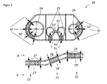
- FIG. 2 an embodiment of an exemplary workpiece 20 is shown in a side view and in a plan view.
- the possible gripping positions of a gripper on the workpiece to be clarified are caused on the one hand by the geometry of the workpiece, and on the other by the design of the gripping element.
- FIG. 2 illustrated exemplary workpiece 20 has an elongated, flat shape with a left region 21, a central region 22 and a right region 23, which are configured in just and are connected via bends with each other. Furthermore, the workpiece has openings 24 to 26.
- the workpiece can now be gripped laterally or frontally via a finger gripper, which engages on the top and bottom of the workpiece in the region of the planar regions 21 to 23.
- these gripping positions 27 to 29 are not single gripping points, but gripping areas 27 'to 29', which extend around or between the permissible gripping points.
- the workpiece can be gripped by one of the gripper fingers of the gripper engages in the openings 24 to 26 of the workpiece, while the other engages the outer periphery.
- a gripping position in which both fingers pass through the apertures 24 to 26 is given with the gripping position 33 and the gripping area 33 ', respectively.
- the device according to the present invention is now designed such that, when the workpieces are handled from the container 5, a large part or all of the gripping positions, which are possible with regard to the geometry of the workpiece and the design of the gripper, also as an allowable gripping position in the control are deposited.
- a plurality of gripping positions are available for gripping the workpieces in the container, so that generally at least one workpiece always lies in the container so that it can actually be gripped with an allowable gripping position.
- this procedure allows 100% emptying of the container.
- the at least two different, defined storage positions provided by the intermediate station ensure that a workpiece gripped in the container can actually also be deposited in a defined manner on the intermediate storage. In this case, the selection of used for storing workpiece trays of the intermediate station in dependence on the gripping position used for gripping takes place.
- an association between the possible gripping positions of the workpiece during the grip in the container and the usable workpiece trays is stored in the control unit 3 on the intermediate station.
- this can be done in the form of a table, which assigns the workpiece positions corresponding to the gripping positions 27 to 32 and 30 to 32.
- the table is preferably stored in the first control component 2, and in particular in the passive part of this control component.
- the permissible gripping positions not necessarily to singular points, so that can not be excluded only by the assignment of the permissible gripping areas to certain workpiece trays that it still comes to collisions.
- the permissible gripping regions can be defined in particular via an off-set with respect to an allowable gripping position arranged within the region.
- the exemplary embodiment of the controller 3 therefore comprises a collision viewing module.
- This contains a 3-D model of the gripper, the workpiece and the clipboard, and calculates based on the concrete gripping position, d. H. in the exemplary embodiment based on the off-set of a predetermined gripping point, whether a collision-free placement of the workpiece on the this clip point associated with clipboard is possible.
- the workpiece is again placed in the container 5 and grasped again.
- the collision viewing according to the invention is preferably carried out live while the gripped workpiece is removed from the container via the gripper 7. This saves cycle time since the calculation does not have to be present before gripping.
- the intermediate station may have a sensor, not shown, which determines the gripping position of the gripper after gripping in the container 5 and before depositing on the intermediate position.
- a sensor determines the gripping position of the gripper after gripping in the container 5 and before depositing on the intermediate position.
- a change in the intended gripping in the container gripping position can be detected, which, for example, may be caused by slipping of the workpiece on the gripper.
- the workpiece placement on the intermediate station and / or the collision check are selected on the basis of the gripping position determined by the sensor. This would allow the collision view to be performed with even more accurate data.
- a sensor for example, a camera or a laser distance sensor can be used.
- the workpieces received on the gripper are moved into the region of the sensor to determine the exact position of the workpiece on the gripper.
- a sensor arranged on the gripper could also be used for this purpose or a sensor between container and clipboard can be arranged.
- the functions that the intermediate station must provide are defined. These are on the one hand the number and structure of the workpiece shelves, on the other hand functions for providing other gripping points for the workpieces on the intermediate station, such as the turning, pivoting, delivery of workpieces and / or workpiece trays.
- preferred gripping points are defined, in particular on the basis of the mechanical properties such as stability in the gripper, and / or the cycle time and the situation on the intermediate station. These gripping points are preferably used when the handle in the container. If the workpiece can be gripped over a preferred gripping point, it may be possible to bypass the intermediate station.
- the category of gripping points influences the design of the grippers and the design of the intermediate station
- a buffer function of the intermediate station can be made available.
- several intermediate stations, as shown in the drawings, can be combined to form a larger intermediate station.
- the cycle times can be done, since depending on the available gripping positions on a workpiece and predefined storage positions, the cycle time of the handle can vary in the container and the recording and positioning can be faster in a predefined Endalage, as the container removal , The cycle times must then be coordinated with each other and the present invention configured intermediate station can act as a buffer and prevent a stoppage of the system or a waiting of the individual operations on each other.
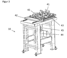
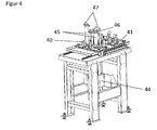
- a first embodiment of an intermediate station according to the invention is in Fig. 3 and 4 shown in more detail.
- the exemplary embodiment has two different nests 40 and 41 on the one hand. These are used to pick up workpieces that have been gripped from the top or bottom.
- the two different nests are required because the top A of the workpiece is designed differently than the bottom B of the workpiece. Depending on whether the workpiece has now been gripped by its upper side A or its lower side B, it is therefore deposited either in the nest 40 or 41.
- the intermediate station on two pins 45 on which a workpiece can be stored.
- the pins 45 engage with their tips 47 in the openings of the workpiece and thus also allow a precise placement of the workpieces.
- the two pins 45 by an adjusting element 46, in the embodiment, a hydraulic or pneumatic cylinder, in height against each other adjustable.
- an adjusting element 46 in the embodiment, a hydraulic or pneumatic cylinder, in height against each other adjustable.
- Workpiece shelf shown allows the placing of the workpieces in 4 defined storage positions.
- the assignment to the gripping areas takes place in such a way that, depending on whether the workpieces are gripped from above or below or laterally or frontally, a deposit takes place in the nests or on the pins.
- the selection then takes place between the two nests or the two workpiece trays provided by the pins.
- the clipboard according to the invention is designed so that by moving the storage elements a change in the storage position of a stored on the clipboard workpiece is possible. This ensures that the stored on the clipboard workpieces can be used with a smaller number of permissible gripping positions of the intermediate station, and preferably with only one or two permissible gripping positions.
- the pins 45 and the nests 40 are designed so that the pins can be pushed through a travel arrangement 44 through the bottom side of the nests, and so can raise a stored in the nest workpiece.
- the removal of the workpieces from the intermediate station always takes place in the position placed on the pins, since this allows an even greater accuracy to be achieved than in the positioning in the nests.
- each of the two nests 40 and 41 are driven over the pins 45.
- the nests 40 and 41 have lateral abutment areas, over which the workpieces are guided in laying in the nests in a fixed position.
- the bottom portion of the nests is recessed so that the pins 45 can be passed therethrough.
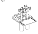
- FIG. 5 is another, slightly modified embodiment of the workpiece trays used on the intermediate station shown in three different storage positions.
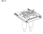
- the three different storage positions are enlarged once again in Fig. 6 . 7 and 8th shown.
- two nests 40 and 41 are again provided, which are arranged on a carriage 42 and can be moved by means of a travel arrangement 43.
- the two nests 41 and 42 each have lateral boundary rails 49 which laterally define the position of the workpieces.
- a storage point 48 is provided in each case, which is arranged in the nest 40 on the left, in the nest 41 on the right side, and on which in the storage on the A side in nest 41 or B side in nest 40 increases arranged part of the workpiece is stored.
- the openings 50 can be seen in the bottom of the nests through which the pins 45 pass.
- the pins 45 are each mounted in a guide 44, and in this separately adjustable in height to raise the stored in the nests 40 and 41 workpieces can. To change the relative height of the tips 47 of the pins to each other, the two pins 45 are raised differently wide.
- Fig. 5 In Fig. 5 and enlarged in Fig. 6 to 8 also, the gripper 60 is shown with the gripping fingers 61, with the respective possible gripping positions on the workpiece.
- a workpiece which has been gripped from above or below, is placed in a nest, depending on the side from which it has been gripped, in the nest 40 or 41.
- the removal of the workpieces is always in the left in Fig. 5 or in Fig. 6 shown, placed on the pins position.
- the workpieces stored in the nests are raised above the pins.
- the respective nest drives over the pins, and the pins are driven through the openings 50 upwards.
- the left or right pin is lifted higher.
- the removal of the workpieces from the intermediate station takes place with at least two permissible gripping points which correspond to the two different orientations of the workpieces (side A or B above). As in Fig. 5 on the left, the workpiece is gripped sideways. From these two different gripping positions, however, a placement of the workpieces in the target tray is possible only on the movement of the picking gripper.
Landscapes
- Engineering & Computer Science (AREA)
- Robotics (AREA)
- Mechanical Engineering (AREA)
- Health & Medical Sciences (AREA)
- General Health & Medical Sciences (AREA)
- Orthopedic Medicine & Surgery (AREA)
- Manipulator (AREA)
- Specific Conveyance Elements (AREA)
- De-Stacking Of Articles (AREA)
Applications Claiming Priority (1)
| Application Number | Priority Date | Filing Date | Title |
|---|---|---|---|
| DE102014008444.2A DE102014008444A1 (de) | 2014-06-06 | 2014-06-06 | Vorrichtung zum automatisierten Entnehmen von in einem Behälter angeordneten Werkstücken |
Publications (3)
| Publication Number | Publication Date |
|---|---|
| EP2952296A2 true EP2952296A2 (fr) | 2015-12-09 |
| EP2952296A3 EP2952296A3 (fr) | 2017-03-29 |
| EP2952296B1 EP2952296B1 (fr) | 2022-12-14 |
Family
ID=52780785
Family Applications (1)
| Application Number | Title | Priority Date | Filing Date |
|---|---|---|---|
| EP15157739.2A Active EP2952296B1 (fr) | 2014-06-06 | 2015-03-05 | Dispositif de prélèvement automatisé de pièces agencées dans un récipient |
Country Status (3)
| Country | Link |
|---|---|
| US (1) | US9855659B2 (fr) |
| EP (1) | EP2952296B1 (fr) |
| DE (1) | DE102014008444A1 (fr) |
Cited By (9)
| Publication number | Priority date | Publication date | Assignee | Title |
|---|---|---|---|---|
| EP3195992A1 (fr) * | 2016-01-23 | 2017-07-26 | SK-Technologies GmbH | Système et procédé pour la détection et le prélèvement automatiques de pièces usinées en désordre |
| CN109108966A (zh) * | 2018-08-14 | 2019-01-01 | 中民筑友科技投资有限公司 | 一种基于视觉识别的钢筋网片抓取控制方法 |
| CN110621451A (zh) * | 2017-04-04 | 2019-12-27 | 牧今科技 | 信息处理装置、拾取系统、物流系统、程序以及信息处理方法 |
| CN111070211A (zh) * | 2020-01-06 | 2020-04-28 | 长沙中联恒通机械有限公司 | 随车机械手一键抓取放回控制方法、装置及系统 |
| US11007643B2 (en) | 2017-04-04 | 2021-05-18 | Mujin, Inc. | Control device, picking system, distribution system, program, control method and production method |
| US11027427B2 (en) | 2017-04-04 | 2021-06-08 | Mujin, Inc. | Control device, picking system, distribution system, program, and control method |
| US11090808B2 (en) | 2017-04-04 | 2021-08-17 | Mujin, Inc. | Control device, picking system, distribution system, program, control method and production method |
| US11097421B2 (en) | 2017-04-04 | 2021-08-24 | Mujin, Inc. | Control device, picking system, distribution system, program, control method and production method |
| EP4043160A1 (fr) * | 2021-02-10 | 2022-08-17 | Inores GmbH | Station de prélèvement de pièces pourvu d'unité de stockage interne |
Families Citing this family (19)
| Publication number | Priority date | Publication date | Assignee | Title |
|---|---|---|---|---|
| US9233470B1 (en) * | 2013-03-15 | 2016-01-12 | Industrial Perception, Inc. | Determining a virtual representation of an environment by projecting texture patterns |
| JP6339534B2 (ja) * | 2015-07-17 | 2018-06-06 | ファナック株式会社 | 最大で二つのワークを把持するハンドを備えたロボットの制御方法およびロボット制御装置 |
| WO2017083574A1 (fr) | 2015-11-13 | 2017-05-18 | Berkshire Grey Inc. | Systèmes de tri et procédés pour assurer le tri de divers objets |
| CN108778636B (zh) * | 2016-02-08 | 2021-11-19 | 伯克希尔格雷股份有限公司 | 用于提供使用运动规划的各种物体的处理的系统和方法 |
| CA3045522C (fr) | 2016-12-06 | 2023-10-03 | Berkshire Grey, Inc. | Systemes et procedes pour permettre le traitement d'objets dans des vehicules |
| DE102017000524A1 (de) | 2017-01-20 | 2018-07-26 | Liebherr-Verzahntechnik Gmbh | Vorrichtung zum automatisierten Entnehmen von in einem Behälter angeordneten Werkstücken |
| DE102017000527A1 (de) | 2017-01-20 | 2018-07-26 | Liebherr-Verzahntechnik Gmbh | Vorrichtung zum automatisierten Entnehmen von in einem Behälter angeordneten Werkstücken |
| JP6404957B2 (ja) * | 2017-01-20 | 2018-10-17 | ファナック株式会社 | 加工機にワークを搬送するロボットを備える加工システム |
| ES2973662T3 (es) | 2017-08-02 | 2024-06-21 | Berkshire Grey Operating Company Inc | Sistemas y procedimientos de adquisición y desplazamiento de objetos con superficies exteriores complejas |
| CN108381509B (zh) * | 2018-03-19 | 2021-03-02 | 京东方科技集团股份有限公司 | 智能抓取装置及其控制方法、智能抓取控制系统 |
| US10676299B2 (en) * | 2018-04-07 | 2020-06-09 | Roca Robotics, Inc. | Item inventory management system with vacuum operated robotic card sorter |
| US11511415B2 (en) * | 2018-06-26 | 2022-11-29 | Teradyne, Inc. | System and method for robotic bin picking |
| DK180068B1 (en) * | 2018-07-16 | 2020-03-19 | Onrobot A/S | Safe Collaborative Gripping Device |
| US10456915B1 (en) * | 2019-01-25 | 2019-10-29 | Mujin, Inc. | Robotic system with enhanced scanning mechanism |
| CN111470244B (zh) * | 2019-01-25 | 2021-02-02 | 牧今科技 | 机器人系统的控制方法以及控制装置 |
| US10870204B2 (en) | 2019-01-25 | 2020-12-22 | Mujin, Inc. | Robotic system control method and controller |
| US11267662B2 (en) | 2019-02-27 | 2022-03-08 | Berkshire Grey, Inc. | Systems and methods for controlling the disgorging of objects in containers by vibratory motion |
| EP4237205A1 (fr) * | 2020-10-29 | 2023-09-06 | Berkshire Grey Operating Company, Inc. | Systèmes et procédés de conditionnement et de traitement automatisés pour expédition avec analyse de posture d'objets |
| DE102024117458A1 (de) * | 2024-06-20 | 2025-12-24 | TRUMPF Werkzeugmaschinen SE + Co. KG | Computergestütztes Palettierungsverfahren |
Citations (2)
| Publication number | Priority date | Publication date | Assignee | Title |
|---|---|---|---|---|
| EP2679352A1 (fr) | 2012-06-29 | 2014-01-01 | LIEBHERR-VERZAHNTECHNIK GmbH | Dispositif de prélèvement automatisée de pièces agencées dans un récipient |
| EP2698234A2 (fr) | 2012-08-17 | 2014-02-19 | LIEBHERR-VERZAHNTECHNIK GmbH | Dispositif de prélèvement automatisée de pièces agencées dans un récipient |
Family Cites Families (8)
| Publication number | Priority date | Publication date | Assignee | Title |
|---|---|---|---|---|
| US3765542A (en) * | 1972-04-03 | 1973-10-16 | Ibm | Self-aligning object placement apparatus |
| AT386977B (de) * | 1984-02-08 | 1988-11-10 | Voest Alpine Ag | Anlage zum beschicken wenigstens einer werkzeugmaschine mit auf paletten bereitgestellten werkstuecken |
| DE102008052440A1 (de) * | 2008-10-21 | 2010-04-22 | Daimler Ag | Verfahren und Vorrichtung zum Vereinzeln von Bauteilen |
| JP5229253B2 (ja) * | 2010-03-11 | 2013-07-03 | 株式会社安川電機 | ロボットシステム及びロボット装置並びにワーク取り出し方法 |
| US8141766B1 (en) * | 2010-09-06 | 2012-03-27 | Cheng Uei Precision Industry Co., Ltd. | Automatic soldering system |
| KR101634463B1 (ko) | 2011-06-29 | 2016-06-28 | 미쓰비시덴키 가부시키가이샤 | 부품 공급 장치 |
| DE202011103280U1 (de) * | 2011-07-16 | 2011-12-13 | Zahoransky Ag | Entnahme- und Ablagevorrichtung |
| JP5447483B2 (ja) * | 2011-10-04 | 2014-03-19 | 株式会社安川電機 | ロボットシステムおよび被加工物の製造方法 |
-
2014
- 2014-06-06 DE DE102014008444.2A patent/DE102014008444A1/de not_active Withdrawn
-
2015
- 2015-03-05 EP EP15157739.2A patent/EP2952296B1/fr active Active
- 2015-06-08 US US14/733,449 patent/US9855659B2/en active Active
Patent Citations (2)
| Publication number | Priority date | Publication date | Assignee | Title |
|---|---|---|---|---|
| EP2679352A1 (fr) | 2012-06-29 | 2014-01-01 | LIEBHERR-VERZAHNTECHNIK GmbH | Dispositif de prélèvement automatisée de pièces agencées dans un récipient |
| EP2698234A2 (fr) | 2012-08-17 | 2014-02-19 | LIEBHERR-VERZAHNTECHNIK GmbH | Dispositif de prélèvement automatisée de pièces agencées dans un récipient |
Cited By (16)
| Publication number | Priority date | Publication date | Assignee | Title |
|---|---|---|---|---|
| EP3195992A1 (fr) * | 2016-01-23 | 2017-07-26 | SK-Technologies GmbH | Système et procédé pour la détection et le prélèvement automatiques de pièces usinées en désordre |
| CN110621451B (zh) * | 2017-04-04 | 2021-07-06 | 牧今科技 | 信息处理装置、拾取系统、物流系统、程序以及信息处理方法 |
| US11097421B2 (en) | 2017-04-04 | 2021-08-24 | Mujin, Inc. | Control device, picking system, distribution system, program, control method and production method |
| US12263598B2 (en) | 2017-04-04 | 2025-04-01 | Mujin, Inc. | Control device, picking system, distribution system, program, control method and production method |
| US11007649B2 (en) | 2017-04-04 | 2021-05-18 | Mujin, Inc. | Information processing apparatus, picking system, distribution system, program and information processing method |
| US11007643B2 (en) | 2017-04-04 | 2021-05-18 | Mujin, Inc. | Control device, picking system, distribution system, program, control method and production method |
| US11027427B2 (en) | 2017-04-04 | 2021-06-08 | Mujin, Inc. | Control device, picking system, distribution system, program, and control method |
| CN110621451A (zh) * | 2017-04-04 | 2019-12-27 | 牧今科技 | 信息处理装置、拾取系统、物流系统、程序以及信息处理方法 |
| US11679503B2 (en) | 2017-04-04 | 2023-06-20 | Mujin, Inc. | Control device, picking system, distribution system, program, control method and production method |
| US11090808B2 (en) | 2017-04-04 | 2021-08-17 | Mujin, Inc. | Control device, picking system, distribution system, program, control method and production method |
| CN109108966A (zh) * | 2018-08-14 | 2019-01-01 | 中民筑友科技投资有限公司 | 一种基于视觉识别的钢筋网片抓取控制方法 |
| CN109108966B (zh) * | 2018-08-14 | 2021-07-30 | 中民筑友科技投资有限公司 | 一种基于视觉识别的钢筋网片抓取控制方法 |
| CN111070211B (zh) * | 2020-01-06 | 2021-06-22 | 中联恒通机械有限公司 | 随车机械手一键抓取放回控制方法、装置及系统 |
| CN111070211A (zh) * | 2020-01-06 | 2020-04-28 | 长沙中联恒通机械有限公司 | 随车机械手一键抓取放回控制方法、装置及系统 |
| EP4043160A1 (fr) * | 2021-02-10 | 2022-08-17 | Inores GmbH | Station de prélèvement de pièces pourvu d'unité de stockage interne |
| WO2022171571A1 (fr) | 2021-02-10 | 2022-08-18 | Inores Gmbh | Station de prélèvement de bacs avec magasin interne |
Also Published As
| Publication number | Publication date |
|---|---|
| EP2952296B1 (fr) | 2022-12-14 |
| DE102014008444A1 (de) | 2015-12-17 |
| US9855659B2 (en) | 2018-01-02 |
| EP2952296A3 (fr) | 2017-03-29 |
| US20150352717A1 (en) | 2015-12-10 |
Similar Documents
| Publication | Publication Date | Title |
|---|---|---|
| EP2952296B1 (fr) | Dispositif de prélèvement automatisé de pièces agencées dans un récipient | |
| DE112012002677T9 (de) | Zuführvorrichtung für Bauelemente | |
| EP1847490B1 (fr) | Dispositif et procédé de palettisation et/ou de dépalettisation automatique de réservoirs | |
| EP3456485B1 (fr) | Optimisation d'un processus automatique permettant la sélection et la manipulation d'un objet par un robot | |
| EP3351351B1 (fr) | Dispositif de prélèvement automatisée de pièces à usiner agencées dans un récipient | |
| DE102012012988A1 (de) | Vorrichtung zur automatisierten Handhabung von Werkstücken | |
| EP2679353A1 (fr) | Dispositif de manipulation automatisée de pièces | |
| DE102016000995A1 (de) | Förderrobotersystem mit dreidimensionalem Sensor | |
| EP2679352A1 (fr) | Dispositif de prélèvement automatisée de pièces agencées dans un récipient | |
| EP2698234A2 (fr) | Dispositif de prélèvement automatisée de pièces agencées dans un récipient | |
| EP3741517A1 (fr) | Procédé de déplacement de produits ainsi que robots de déplacement appropriés | |
| WO2018024311A1 (fr) | Système de préparation de commandes | |
| DE102017121557B4 (de) | Verfahren und Vorrichtung zur Förderung und Positionierung von Werkstücken | |
| AT516279A4 (de) | Fertigungsanlage mit Manipulationsvorrichtung | |
| EP3281894A1 (fr) | Dispositif de réception, de transfert et de dépôt de produits avec modification de leur agencement géométrique | |
| WO2021174274A1 (fr) | Dispositif et procédé pour retourner des tôles | |
| DE102019105834B4 (de) | Greifvorrichtung, Vereinzelungsvorrichtung sowie Verfahren zum Greifen von Körpern und Verwendung einer Greifvorrichtung | |
| EP3195992A1 (fr) | Système et procédé pour la détection et le prélèvement automatiques de pièces usinées en désordre | |
| DE102012013029A1 (de) | Vorrichtung zur automatischen Handhabung von ungeordneten Werkstücken | |
| DE102016119894A1 (de) | Robotische Transportvorrichtung zum Transportieren von Kleinteilen und mit der robotischen Vorrichtung durchführbares Verfahren | |
| DE102019200930A1 (de) | Vorrichtung und Verfahren zum automatischen Handhaben von Lagereinheiten | |
| DE69619115T2 (de) | Verfahren zum zuvorkommen von interferenz für industrierobotor | |
| DE102012013023A1 (de) | Vorrichtung zur automatisierten Handhabung von Werkstücken | |
| DE102020108037B4 (de) | Positionierungseinrichtung und Verfahren zur Positionierung von Werkstücken | |
| DE102009014636B4 (de) | Kommissionierung von Schnittblumen und/oder Pflanzen mit einem Roboter |
Legal Events
| Date | Code | Title | Description |
|---|---|---|---|
| PUAI | Public reference made under article 153(3) epc to a published international application that has entered the european phase |
Free format text: ORIGINAL CODE: 0009012 |
|
| AK | Designated contracting states |
Kind code of ref document: A2 Designated state(s): AL AT BE BG CH CY CZ DE DK EE ES FI FR GB GR HR HU IE IS IT LI LT LU LV MC MK MT NL NO PL PT RO RS SE SI SK SM TR |
|
| AX | Request for extension of the european patent |
Extension state: BA ME |
|
| PUAL | Search report despatched |
Free format text: ORIGINAL CODE: 0009013 |
|
| AK | Designated contracting states |
Kind code of ref document: A3 Designated state(s): AL AT BE BG CH CY CZ DE DK EE ES FI FR GB GR HR HU IE IS IT LI LT LU LV MC MK MT NL NO PL PT RO RS SE SI SK SM TR |
|
| AX | Request for extension of the european patent |
Extension state: BA ME |
|
| RIC1 | Information provided on ipc code assigned before grant |
Ipc: B25J 9/00 20060101AFI20170222BHEP Ipc: B65G 47/14 20060101ALI20170222BHEP Ipc: B25J 19/02 20060101ALI20170222BHEP |
|
| STAA | Information on the status of an ep patent application or granted ep patent |
Free format text: STATUS: REQUEST FOR EXAMINATION WAS MADE |
|
| 17P | Request for examination filed |
Effective date: 20170929 |
|
| STAA | Information on the status of an ep patent application or granted ep patent |
Free format text: STATUS: EXAMINATION IS IN PROGRESS |
|
| 17Q | First examination report despatched |
Effective date: 20201120 |
|
| GRAP | Despatch of communication of intention to grant a patent |
Free format text: ORIGINAL CODE: EPIDOSNIGR1 |
|
| STAA | Information on the status of an ep patent application or granted ep patent |
Free format text: STATUS: GRANT OF PATENT IS INTENDED |
|
| INTG | Intention to grant announced |
Effective date: 20220912 |
|
| RIN1 | Information on inventor provided before grant (corrected) |
Inventor name: RIEDMILLER, BERNHARD Inventor name: HAENSCHKE, DAVID Inventor name: MATTERN, THOMAS Inventor name: MUNDT, ALOIS, DR. |
|
| GRAS | Grant fee paid |
Free format text: ORIGINAL CODE: EPIDOSNIGR3 |
|
| GRAA | (expected) grant |
Free format text: ORIGINAL CODE: 0009210 |
|
| STAA | Information on the status of an ep patent application or granted ep patent |
Free format text: STATUS: THE PATENT HAS BEEN GRANTED |
|
| AK | Designated contracting states |
Kind code of ref document: B1 Designated state(s): AL AT BE BG CH CY CZ DE DK EE ES FI FR GB GR HR HU IE IS IT LI LT LU LV MC MK MT NL NO PL PT RO RS SE SI SK SM TR |
|
| REG | Reference to a national code |
Ref country code: GB Ref legal event code: FG4D Free format text: NOT ENGLISH |
|
| REG | Reference to a national code |
Ref country code: CH Ref legal event code: EP |
|
| REG | Reference to a national code |
Ref country code: DE Ref legal event code: R096 Ref document number: 502015016190 Country of ref document: DE |
|
| REG | Reference to a national code |
Ref country code: IE Ref legal event code: FG4D Free format text: LANGUAGE OF EP DOCUMENT: GERMAN |
|
| REG | Reference to a national code |
Ref country code: AT Ref legal event code: REF Ref document number: 1537398 Country of ref document: AT Kind code of ref document: T Effective date: 20230115 |
|
| REG | Reference to a national code |
Ref country code: LT Ref legal event code: MG9D |
|
| REG | Reference to a national code |
Ref country code: NL Ref legal event code: MP Effective date: 20221214 |
|
| PG25 | Lapsed in a contracting state [announced via postgrant information from national office to epo] |
Ref country code: SE Free format text: LAPSE BECAUSE OF FAILURE TO SUBMIT A TRANSLATION OF THE DESCRIPTION OR TO PAY THE FEE WITHIN THE PRESCRIBED TIME-LIMIT Effective date: 20221214 Ref country code: NO Free format text: LAPSE BECAUSE OF FAILURE TO SUBMIT A TRANSLATION OF THE DESCRIPTION OR TO PAY THE FEE WITHIN THE PRESCRIBED TIME-LIMIT Effective date: 20230314 Ref country code: LT Free format text: LAPSE BECAUSE OF FAILURE TO SUBMIT A TRANSLATION OF THE DESCRIPTION OR TO PAY THE FEE WITHIN THE PRESCRIBED TIME-LIMIT Effective date: 20221214 Ref country code: FI Free format text: LAPSE BECAUSE OF FAILURE TO SUBMIT A TRANSLATION OF THE DESCRIPTION OR TO PAY THE FEE WITHIN THE PRESCRIBED TIME-LIMIT Effective date: 20221214 |
|
| PG25 | Lapsed in a contracting state [announced via postgrant information from national office to epo] |
Ref country code: RS Free format text: LAPSE BECAUSE OF FAILURE TO SUBMIT A TRANSLATION OF THE DESCRIPTION OR TO PAY THE FEE WITHIN THE PRESCRIBED TIME-LIMIT Effective date: 20221214 Ref country code: LV Free format text: LAPSE BECAUSE OF FAILURE TO SUBMIT A TRANSLATION OF THE DESCRIPTION OR TO PAY THE FEE WITHIN THE PRESCRIBED TIME-LIMIT Effective date: 20221214 Ref country code: HR Free format text: LAPSE BECAUSE OF FAILURE TO SUBMIT A TRANSLATION OF THE DESCRIPTION OR TO PAY THE FEE WITHIN THE PRESCRIBED TIME-LIMIT Effective date: 20221214 Ref country code: GR Free format text: LAPSE BECAUSE OF FAILURE TO SUBMIT A TRANSLATION OF THE DESCRIPTION OR TO PAY THE FEE WITHIN THE PRESCRIBED TIME-LIMIT Effective date: 20230315 |
|
| PG25 | Lapsed in a contracting state [announced via postgrant information from national office to epo] |
Ref country code: NL Free format text: LAPSE BECAUSE OF FAILURE TO SUBMIT A TRANSLATION OF THE DESCRIPTION OR TO PAY THE FEE WITHIN THE PRESCRIBED TIME-LIMIT Effective date: 20221214 |
|
| PG25 | Lapsed in a contracting state [announced via postgrant information from national office to epo] |
Ref country code: SM Free format text: LAPSE BECAUSE OF FAILURE TO SUBMIT A TRANSLATION OF THE DESCRIPTION OR TO PAY THE FEE WITHIN THE PRESCRIBED TIME-LIMIT Effective date: 20221214 Ref country code: RO Free format text: LAPSE BECAUSE OF FAILURE TO SUBMIT A TRANSLATION OF THE DESCRIPTION OR TO PAY THE FEE WITHIN THE PRESCRIBED TIME-LIMIT Effective date: 20221214 Ref country code: PT Free format text: LAPSE BECAUSE OF FAILURE TO SUBMIT A TRANSLATION OF THE DESCRIPTION OR TO PAY THE FEE WITHIN THE PRESCRIBED TIME-LIMIT Effective date: 20230414 Ref country code: ES Free format text: LAPSE BECAUSE OF FAILURE TO SUBMIT A TRANSLATION OF THE DESCRIPTION OR TO PAY THE FEE WITHIN THE PRESCRIBED TIME-LIMIT Effective date: 20221214 Ref country code: EE Free format text: LAPSE BECAUSE OF FAILURE TO SUBMIT A TRANSLATION OF THE DESCRIPTION OR TO PAY THE FEE WITHIN THE PRESCRIBED TIME-LIMIT Effective date: 20221214 Ref country code: CZ Free format text: LAPSE BECAUSE OF FAILURE TO SUBMIT A TRANSLATION OF THE DESCRIPTION OR TO PAY THE FEE WITHIN THE PRESCRIBED TIME-LIMIT Effective date: 20221214 |
|
| PG25 | Lapsed in a contracting state [announced via postgrant information from national office to epo] |
Ref country code: SK Free format text: LAPSE BECAUSE OF FAILURE TO SUBMIT A TRANSLATION OF THE DESCRIPTION OR TO PAY THE FEE WITHIN THE PRESCRIBED TIME-LIMIT Effective date: 20221214 Ref country code: PL Free format text: LAPSE BECAUSE OF FAILURE TO SUBMIT A TRANSLATION OF THE DESCRIPTION OR TO PAY THE FEE WITHIN THE PRESCRIBED TIME-LIMIT Effective date: 20221214 Ref country code: IS Free format text: LAPSE BECAUSE OF FAILURE TO SUBMIT A TRANSLATION OF THE DESCRIPTION OR TO PAY THE FEE WITHIN THE PRESCRIBED TIME-LIMIT Effective date: 20230414 Ref country code: AL Free format text: LAPSE BECAUSE OF FAILURE TO SUBMIT A TRANSLATION OF THE DESCRIPTION OR TO PAY THE FEE WITHIN THE PRESCRIBED TIME-LIMIT Effective date: 20221214 |
|
| REG | Reference to a national code |
Ref country code: DE Ref legal event code: R097 Ref document number: 502015016190 Country of ref document: DE |
|
| PLBE | No opposition filed within time limit |
Free format text: ORIGINAL CODE: 0009261 |
|
| STAA | Information on the status of an ep patent application or granted ep patent |
Free format text: STATUS: NO OPPOSITION FILED WITHIN TIME LIMIT |
|
| PG25 | Lapsed in a contracting state [announced via postgrant information from national office to epo] |
Ref country code: MC Free format text: LAPSE BECAUSE OF FAILURE TO SUBMIT A TRANSLATION OF THE DESCRIPTION OR TO PAY THE FEE WITHIN THE PRESCRIBED TIME-LIMIT Effective date: 20221214 Ref country code: DK Free format text: LAPSE BECAUSE OF FAILURE TO SUBMIT A TRANSLATION OF THE DESCRIPTION OR TO PAY THE FEE WITHIN THE PRESCRIBED TIME-LIMIT Effective date: 20221214 |
|
| REG | Reference to a national code |
Ref country code: CH Ref legal event code: PL |
|
| 26N | No opposition filed |
Effective date: 20230915 |
|
| GBPC | Gb: european patent ceased through non-payment of renewal fee |
Effective date: 20230314 |
|
| PG25 | Lapsed in a contracting state [announced via postgrant information from national office to epo] |
Ref country code: SI Free format text: LAPSE BECAUSE OF FAILURE TO SUBMIT A TRANSLATION OF THE DESCRIPTION OR TO PAY THE FEE WITHIN THE PRESCRIBED TIME-LIMIT Effective date: 20221214 |
|
| REG | Reference to a national code |
Ref country code: BE Ref legal event code: MM Effective date: 20230331 |
|
| PG25 | Lapsed in a contracting state [announced via postgrant information from national office to epo] |
Ref country code: LU Free format text: LAPSE BECAUSE OF NON-PAYMENT OF DUE FEES Effective date: 20230305 |
|
| REG | Reference to a national code |
Ref country code: IE Ref legal event code: MM4A |
|
| PG25 | Lapsed in a contracting state [announced via postgrant information from national office to epo] |
Ref country code: GB Free format text: LAPSE BECAUSE OF NON-PAYMENT OF DUE FEES Effective date: 20230314 |
|
| PG25 | Lapsed in a contracting state [announced via postgrant information from national office to epo] |
Ref country code: LI Free format text: LAPSE BECAUSE OF NON-PAYMENT OF DUE FEES Effective date: 20230331 Ref country code: IE Free format text: LAPSE BECAUSE OF NON-PAYMENT OF DUE FEES Effective date: 20230305 Ref country code: GB Free format text: LAPSE BECAUSE OF NON-PAYMENT OF DUE FEES Effective date: 20230314 Ref country code: CH Free format text: LAPSE BECAUSE OF NON-PAYMENT OF DUE FEES Effective date: 20230331 |
|
| PG25 | Lapsed in a contracting state [announced via postgrant information from national office to epo] |
Ref country code: BE Free format text: LAPSE BECAUSE OF NON-PAYMENT OF DUE FEES Effective date: 20230331 |
|
| REG | Reference to a national code |
Ref country code: AT Ref legal event code: MM01 Ref document number: 1537398 Country of ref document: AT Kind code of ref document: T Effective date: 20230305 |
|
| PG25 | Lapsed in a contracting state [announced via postgrant information from national office to epo] |
Ref country code: AT Free format text: LAPSE BECAUSE OF NON-PAYMENT OF DUE FEES Effective date: 20230305 |
|
| PG25 | Lapsed in a contracting state [announced via postgrant information from national office to epo] |
Ref country code: AT Free format text: LAPSE BECAUSE OF NON-PAYMENT OF DUE FEES Effective date: 20230305 |
|
| PG25 | Lapsed in a contracting state [announced via postgrant information from national office to epo] |
Ref country code: BG Free format text: LAPSE BECAUSE OF FAILURE TO SUBMIT A TRANSLATION OF THE DESCRIPTION OR TO PAY THE FEE WITHIN THE PRESCRIBED TIME-LIMIT Effective date: 20221214 |
|
| PG25 | Lapsed in a contracting state [announced via postgrant information from national office to epo] |
Ref country code: BG Free format text: LAPSE BECAUSE OF FAILURE TO SUBMIT A TRANSLATION OF THE DESCRIPTION OR TO PAY THE FEE WITHIN THE PRESCRIBED TIME-LIMIT Effective date: 20221214 |
|
| PGFP | Annual fee paid to national office [announced via postgrant information from national office to epo] |
Ref country code: DE Payment date: 20250331 Year of fee payment: 11 |
|
| PGFP | Annual fee paid to national office [announced via postgrant information from national office to epo] |
Ref country code: IT Payment date: 20250327 Year of fee payment: 11 |
|
| PG25 | Lapsed in a contracting state [announced via postgrant information from national office to epo] |
Ref country code: CY Free format text: LAPSE BECAUSE OF FAILURE TO SUBMIT A TRANSLATION OF THE DESCRIPTION OR TO PAY THE FEE WITHIN THE PRESCRIBED TIME-LIMIT; INVALID AB INITIO Effective date: 20150305 |
|
| PG25 | Lapsed in a contracting state [announced via postgrant information from national office to epo] |
Ref country code: HU Free format text: LAPSE BECAUSE OF FAILURE TO SUBMIT A TRANSLATION OF THE DESCRIPTION OR TO PAY THE FEE WITHIN THE PRESCRIBED TIME-LIMIT; INVALID AB INITIO Effective date: 20150305 |
|
| PG25 | Lapsed in a contracting state [announced via postgrant information from national office to epo] |
Ref country code: TR Free format text: LAPSE BECAUSE OF FAILURE TO SUBMIT A TRANSLATION OF THE DESCRIPTION OR TO PAY THE FEE WITHIN THE PRESCRIBED TIME-LIMIT Effective date: 20221214 |
|
| PGFP | Annual fee paid to national office [announced via postgrant information from national office to epo] |
Ref country code: FR Payment date: 20260330 Year of fee payment: 12 |