EP2952365A2 - Passage tournant pour roue de véhicule - Google Patents
Passage tournant pour roue de véhicule Download PDFInfo
- Publication number
- EP2952365A2 EP2952365A2 EP15168971.8A EP15168971A EP2952365A2 EP 2952365 A2 EP2952365 A2 EP 2952365A2 EP 15168971 A EP15168971 A EP 15168971A EP 2952365 A2 EP2952365 A2 EP 2952365A2
- Authority
- EP
- European Patent Office
- Prior art keywords
- lubricant
- compressed air
- wheel hub
- annulus
- wheel
- Prior art date
- Legal status (The legal status is an assumption and is not a legal conclusion. Google has not performed a legal analysis and makes no representation as to the accuracy of the status listed.)
- Granted
Links
Images
Classifications
-
- B—PERFORMING OPERATIONS; TRANSPORTING
- B60—VEHICLES IN GENERAL
- B60B—VEHICLE WHEELS; CASTORS; AXLES FOR WHEELS OR CASTORS; INCREASING WHEEL ADHESION
- B60B27/00—Hubs
- B60B27/0073—Hubs characterised by sealing means
-
- B—PERFORMING OPERATIONS; TRANSPORTING
- B60—VEHICLES IN GENERAL
- B60C—VEHICLE TYRES; TYRE INFLATION; TYRE CHANGING; CONNECTING VALVES TO INFLATABLE ELASTIC BODIES IN GENERAL; DEVICES OR ARRANGEMENTS RELATED TO TYRES
- B60C23/00—Devices for measuring, signalling, controlling, or distributing tyre pressure or temperature, specially adapted for mounting on vehicles; Arrangement of tyre inflating devices on vehicles, e.g. of pumps or of tanks; Tyre cooling arrangements
- B60C23/001—Devices for manually or automatically controlling or distributing tyre pressure whilst the vehicle is moving
- B60C23/003—Devices for manually or automatically controlling or distributing tyre pressure whilst the vehicle is moving comprising rotational joints between vehicle-mounted pressure sources and the tyres
- B60C23/00345—Details of the rotational joints
-
- B—PERFORMING OPERATIONS; TRANSPORTING
- B60—VEHICLES IN GENERAL
- B60B—VEHICLE WHEELS; CASTORS; AXLES FOR WHEELS OR CASTORS; INCREASING WHEEL ADHESION
- B60B27/00—Hubs
-
- B—PERFORMING OPERATIONS; TRANSPORTING
- B60—VEHICLES IN GENERAL
- B60B—VEHICLE WHEELS; CASTORS; AXLES FOR WHEELS OR CASTORS; INCREASING WHEEL ADHESION
- B60B27/00—Hubs
- B60B27/0047—Hubs characterised by functional integration of other elements
-
- B—PERFORMING OPERATIONS; TRANSPORTING
- B60—VEHICLES IN GENERAL
- B60C—VEHICLE TYRES; TYRE INFLATION; TYRE CHANGING; CONNECTING VALVES TO INFLATABLE ELASTIC BODIES IN GENERAL; DEVICES OR ARRANGEMENTS RELATED TO TYRES
- B60C23/00—Devices for measuring, signalling, controlling, or distributing tyre pressure or temperature, specially adapted for mounting on vehicles; Arrangement of tyre inflating devices on vehicles, e.g. of pumps or of tanks; Tyre cooling arrangements
- B60C23/001—Devices for manually or automatically controlling or distributing tyre pressure whilst the vehicle is moving
- B60C23/003—Devices for manually or automatically controlling or distributing tyre pressure whilst the vehicle is moving comprising rotational joints between vehicle-mounted pressure sources and the tyres
- B60C23/00309—Devices for manually or automatically controlling or distributing tyre pressure whilst the vehicle is moving comprising rotational joints between vehicle-mounted pressure sources and the tyres characterised by the location of the components, e.g. valves, sealings, conduits or sensors
- B60C23/00318—Devices for manually or automatically controlling or distributing tyre pressure whilst the vehicle is moving comprising rotational joints between vehicle-mounted pressure sources and the tyres characterised by the location of the components, e.g. valves, sealings, conduits or sensors on the wheels or the hubs
-
- B—PERFORMING OPERATIONS; TRANSPORTING
- B60—VEHICLES IN GENERAL
- B60C—VEHICLE TYRES; TYRE INFLATION; TYRE CHANGING; CONNECTING VALVES TO INFLATABLE ELASTIC BODIES IN GENERAL; DEVICES OR ARRANGEMENTS RELATED TO TYRES
- B60C23/00—Devices for measuring, signalling, controlling, or distributing tyre pressure or temperature, specially adapted for mounting on vehicles; Arrangement of tyre inflating devices on vehicles, e.g. of pumps or of tanks; Tyre cooling arrangements
- B60C23/001—Devices for manually or automatically controlling or distributing tyre pressure whilst the vehicle is moving
- B60C23/003—Devices for manually or automatically controlling or distributing tyre pressure whilst the vehicle is moving comprising rotational joints between vehicle-mounted pressure sources and the tyres
- B60C23/00309—Devices for manually or automatically controlling or distributing tyre pressure whilst the vehicle is moving comprising rotational joints between vehicle-mounted pressure sources and the tyres characterised by the location of the components, e.g. valves, sealings, conduits or sensors
- B60C23/00336—Devices for manually or automatically controlling or distributing tyre pressure whilst the vehicle is moving comprising rotational joints between vehicle-mounted pressure sources and the tyres characterised by the location of the components, e.g. valves, sealings, conduits or sensors on the axles
-
- B—PERFORMING OPERATIONS; TRANSPORTING
- B60—VEHICLES IN GENERAL
- B60C—VEHICLE TYRES; TYRE INFLATION; TYRE CHANGING; CONNECTING VALVES TO INFLATABLE ELASTIC BODIES IN GENERAL; DEVICES OR ARRANGEMENTS RELATED TO TYRES
- B60C23/00—Devices for measuring, signalling, controlling, or distributing tyre pressure or temperature, specially adapted for mounting on vehicles; Arrangement of tyre inflating devices on vehicles, e.g. of pumps or of tanks; Tyre cooling arrangements
- B60C23/001—Devices for manually or automatically controlling or distributing tyre pressure whilst the vehicle is moving
- B60C23/003—Devices for manually or automatically controlling or distributing tyre pressure whilst the vehicle is moving comprising rotational joints between vehicle-mounted pressure sources and the tyres
- B60C23/00354—Details of valves
-
- B—PERFORMING OPERATIONS; TRANSPORTING
- B60—VEHICLES IN GENERAL
- B60C—VEHICLE TYRES; TYRE INFLATION; TYRE CHANGING; CONNECTING VALVES TO INFLATABLE ELASTIC BODIES IN GENERAL; DEVICES OR ARRANGEMENTS RELATED TO TYRES
- B60C23/00—Devices for measuring, signalling, controlling, or distributing tyre pressure or temperature, specially adapted for mounting on vehicles; Arrangement of tyre inflating devices on vehicles, e.g. of pumps or of tanks; Tyre cooling arrangements
- B60C23/001—Devices for manually or automatically controlling or distributing tyre pressure whilst the vehicle is moving
- B60C23/003—Devices for manually or automatically controlling or distributing tyre pressure whilst the vehicle is moving comprising rotational joints between vehicle-mounted pressure sources and the tyres
- B60C23/00363—Details of sealings
-
- B—PERFORMING OPERATIONS; TRANSPORTING
- B60—VEHICLES IN GENERAL
- B60C—VEHICLE TYRES; TYRE INFLATION; TYRE CHANGING; CONNECTING VALVES TO INFLATABLE ELASTIC BODIES IN GENERAL; DEVICES OR ARRANGEMENTS RELATED TO TYRES
- B60C23/00—Devices for measuring, signalling, controlling, or distributing tyre pressure or temperature, specially adapted for mounting on vehicles; Arrangement of tyre inflating devices on vehicles, e.g. of pumps or of tanks; Tyre cooling arrangements
- B60C23/001—Devices for manually or automatically controlling or distributing tyre pressure whilst the vehicle is moving
- B60C23/003—Devices for manually or automatically controlling or distributing tyre pressure whilst the vehicle is moving comprising rotational joints between vehicle-mounted pressure sources and the tyres
- B60C23/00372—Devices for manually or automatically controlling or distributing tyre pressure whilst the vehicle is moving comprising rotational joints between vehicle-mounted pressure sources and the tyres characterised by fluid diagrams
-
- F—MECHANICAL ENGINEERING; LIGHTING; HEATING; WEAPONS; BLASTING
- F16—ENGINEERING ELEMENTS AND UNITS; GENERAL MEASURES FOR PRODUCING AND MAINTAINING EFFECTIVE FUNCTIONING OF MACHINES OR INSTALLATIONS; THERMAL INSULATION IN GENERAL
- F16L—PIPES; JOINTS OR FITTINGS FOR PIPES; SUPPORTS FOR PIPES, CABLES OR PROTECTIVE TUBING; MEANS FOR THERMAL INSULATION IN GENERAL
- F16L27/00—Adjustable joints; Joints allowing movement
- F16L27/08—Adjustable joints; Joints allowing movement allowing adjustment or movement only about the axis of one pipe
- F16L27/087—Joints with radial fluid passages
Definitions
- the invention relates to a rotary feedthrough for a motor vehicle wheel with tire pressure control.
- a wheel of a motor vehicle usually has a wheel hub which is rotatably mounted on a wheel carrier (for example, knuckle or axle funnel).
- a tire pressure regulating device is provided to adjust the air pressure in the tire mounted on the wheel hub to a desired value.
- it In order to be able to supply the compressed air required for this purpose to the tire, it must be transferred, for example, starting from a central compressed air source, from the respective wheel carrier to the wheel hub mounted thereon. The same applies in the opposite direction for emptying the tire.
- the rotary feedthrough which has a substantially annular space between the wheel carrier and the wheel hub, in which a compressed air annulus is formed.
- a compressed-air annulus formed in the space between the wheel carrier and the wheel hub must be reliably sealed against the environment and in particular with respect to the remaining gap.
- sealing rings in particular Radial shaft sealing rings, carried out, which delimit the compressed air annulus on both sides and in particular seal against formed in the remaining space formed lubricant annular spaces, which may serve for example, the lubrication of the sealing rings and / or bearings for supporting the wheel hub on the wheel.
- Tire pressure control systems may be, for example, single-channel, i. with only a single leading to the valve compressed air channel in the wheel hub, or multi-channel, in particular two-channel, be formed.
- an additional compressed air channel in the wheel hub serves to control the switching position of the valve.
- Two-channel systems have the advantage that a standard valve can be used on the tire whose air pressure is to be controllable.
- a standard valve usually has a compressed air connection and a working connection (2/2-way valve) and possibly a venting connection (3/2-way valve).
- the valve can also have a control connection, which is actuated via the additional compressed air channel.
- the valve can optionally be actuated to connect the compressed air connection or the vent connection to the working connection for the passage of compressed air or to block these connections against each other.
- the valve is biased in a blocking state to to maintain the tire pressure in the event of a pressure or force failure at the control port.
- the rotary feedthrough must have at least two compressed air channels in the wheel hub, so that in the space between the wheel and the hub and at least two compressed air annular spaces must be formed to the compressed air channels of the hub with associated compressed air channels to connect the wheel carrier.
- These compressed air annular spaces which may have very different pressures must be reliable and in particular also sealed against each other, such as by between them and on the two sides of respective sealing rings are provided.
- lubricant such as grease or lubricating oil can be passed through lubricant channels from the wheel into lubricant annular spaces in the said space between the wheel and the hub in addition to the compressed air Ring rooms are provided.
- the lubricant can reach the respective sealing rings limiting the respective lubricant annulus.
- the wear but not the relatively high number of wearing parts can be reduced.
- such an arrangement requires a relatively large overall depth (extension of said gap along the arrangement direction of the sealing rings).
- the object of the present invention is to provide a rotary feedthrough with a simple and compact design, which is low-wear and inexpensive.
- a rotary feedthrough with the features of claim 1 and in particular in that in a space between the wheel and the hub, a compressed air annulus and at least one lubricant annulus are formed, which are sealed against each other, wherein the compressed air annulus communicates with a compressed air passage of the wheel carrier and with a compressed air passage of the wheel hub, wherein the compressed air passage of the wheel hub further communicates with a controllable valve to selectively fill or empty a tire of the vehicle wheel with compressed air, and wherein the lubricant annulus with a lubricant passage of the wheel carrier and communicates with a lubricant passage of the wheel hub, wherein the lubricant passage of the wheel hub leads to a control port of the valve to selectively control the valve for the passage of compressed air.
- the said controllable valve may be a standard valve as described above, which is simple and inexpensive.
- the compressed air passage of the wheel hub can supply compressed air to the compressed air port of the valve, while the valve can be controlled via the pressure applied to the control port (directly or indirectly) pressure of the lubricant, which is supplied to the control port through the lubricant channel of the wheel hub.
- the rotary feedthrough according to the invention is a two-channel system, the two channels, however, differ from other two-channel systems in that one channel carries compressed air, the other channel but lubricant.
- the overall depth of the rotary feedthrough i. Their expansion relative to the (radial and / or axial) gap between the wheel carrier and the wheel hub, comparatively low and be comparable to the depth of a single-channel solution.
- the formation of a single compressed air annulus in said space is sufficient.
- the second channel of the wheel hub is not a compressed air channel, but a lubricant channel, a lubricant annular space can be used to supply the second channel and thus to control the valve instead of another compressed air annulus, which in the said space for sealing the compressed air annulus typically present anyway.
- the compressed air annulus for supplying the one (compressed air) channel of the wheel hub and the lubricant annulus for supplying the other (lubricant) channel of the wheel hub directly adjacent to each other. In this way, the overall depth of the rotary feedthrough is minimized and contributes to a compact design of the rotary feedthrough.
- the lubricant annulus can be supplied by the lubricant channel of the wheel carrier in particular with lubricating oil or grease or other lubricant.
- This lubricant can serve to lubricate sealing elements such as sealing rings, in particular radial shaft seals, for sealing the compressed air annulus, so that they seal reliably and are protected against premature wear.
- the lubricant can also serve as a pressure medium in addition to this function, the pressure can be adjusted, for example, Radmonograph mineral and over the space between the wheel and the wheel hub away by means of the lubricant channel of the wheel hub can be transferred to the valve to the valve Taxes.
- the lubricant used may be, in particular, the same lubricant that is also used for lubricating other components, for example for lubricating bearings for supporting the wheel hub on the wheel carrier or a transmission (for example a reduction gear between a drive shaft guided in the wheel carrier and the wheel hub).
- the compressed air annulus and the lubricant annulus may be delimited by a sealing ring against each other (in the axial or radial direction).
- a sealing ring against each other in the axial or radial direction.
- To delimit the compressed air annulus and / or the lubricant annulus of the respective annulus is in particular in two opposite Directions (corresponding to the extent of the gap formed between the wheel and the wheel hub) delimited by a respective sealing ring with respect to the remaining space.
- the use of sealing rings, which may in particular be radial shaft seals, in such an arrangement ensures reliable sealing of the respective annular spaces, is structurally simple and enables a compact rotary feedthrough.
- the sealing effect of the compressed air annulus limiting respective sealing ring is controllable such that by increasing the pressure of a located in the lubricant annulus lubricant, a pressing force of the sealing ring relative to the wheel carrier or the wheel hub is increased.
- the sealing rings can be "switchable", so to speak. This means that on the pressure of the lubricant, the pressure force of respective sealing rings and thus their respective sealing effect on the one hand and resulting wear on the other hand can be selectively adjusted.
- the pressing force can be temporarily changed to temporarily adjust the sealing effect of the sealing rings.
- a relatively low normal pressure of the lubricant may be sufficient for a sealing ring provided between the compressed-air annular space and a respective lubricant annulus to reliably seal these annular spaces against each other with minimal wear.
- the pressure of the compressed air decreases again, the pressure of the lubricant and thus the pressure force can be reduced again to minimize the dependent of the pressing force wear of the sealing rings.
- the gap formed between the wheel carrier and the wheel hub may extend from the wheel carrier to the wheel hub in the radial direction, in which case the compressed air annulus and the respective lubricant annulus are sealed against each other in the axial direction.
- said gap extends from the wheel carrier to the wheel hub in the axial direction, wherein the compressed-air annulus and the respective lubricant annulus are sealed in the radial direction against each other.
- exactly one communicating with a compressed air channel of the wheel hub compressed air annulus is formed in said space between the wheel carrier and the wheel hub.
- further compressed air annular spaces can be provided for additional supply of the same compressed air duct or further compressed air ducts of the wheel hub.
- a particularly compact overall depth of the rotary feedthrough, however, is achieved in that only exactly one such compressed air annular space is provided.
- the wheel hub has exactly one compressed air channel which communicates with the compressed air annular space formed in said intermediate space.
- the wheel hub may also have other compressed air ducts supplied across the said gap for other purposes.
- a rotary feedthrough in which only a compressed air channel is provided in the wheel hub in contrast, has a simpler structure.
- a plurality of lubricant annular spaces communicating with the lubricant channel of the wheel carrier may be formed in the intermediate space between the wheel carrier and the wheel hub.
- the compressed air annulus to his adjacent to both sides of a respective lubricant annulus and sealed in this way reliable.
- the respective lubricant annular spaces are supplied together with lubricant via the mentioned lubricant channel of the wheel carrier.
- a plurality of lubricant annular spaces can also be formed in said intermediate space between the wheel carrier and the wheel hub, which communicate with a respective own lubricant channel of the wheel carrier.
- the wheel carrier can therefore also have a plurality of lubricant channels for supplying respectively different lubricant annular spaces.
- the lubricant channel of the wheel hub can be connected to the control port of the valve directly or via a pressure conversion device. Whether a pressure conversion device is required depends on the valve used and in particular its control connection. If the control port of the valve is suitable, To convert hydraulic pressures directly into respective switching states of the valve, the lubricant channel of the wheel hub can be connected directly to the control terminal, so that can be dispensed with a pressure conversion device. In contrast, it may be advantageous to use particularly simple and widely used mechanically switchable valves, such as 2/2 or 3/2-way valves.
- a pressure conversion device can be interposed, which is the input side connected to the lubricant channel of the wheel hub and the hydraulic pressure of the lubricant on the output side in a mechanical movement, such as a piston or plunger, converts, through which the control terminal the valve is then actuated.
- two lubricant annular spaces are formed in said intermediate space between the wheel carrier and the wheel hub, wherein the compressed-air annular space is formed between the two lubricant annular spaces.
- the compressed air annulus is flanked on its two sides by a lubricant annulus and sealed in this way reliable.
- the rotary feedthrough has four sealing rings, wherein each of the two lubricant annular spaces is bounded on both sides by one of the four sealing rings, wherein the compressed air annulus is bounded on both sides by the two middle of the four sealing rings.
- the four sealing rings eg, in axial or radial sequence
- a total of three rooms namely centrally the compressed air annulus and on both sides for this purpose each a lubricant annulus.
- the sealing rings ensure the seal in particular between the lubricant annular spaces and the compressed air annulus.
- the compressed air annular space can be formed axially between the two lubricant annular spaces, wherein the compressed air annulus and the two lubricant annular spaces in the axial Direction are limited by the sealing rings.
- each of said four sealing rings is formed as a radial shaft sealing ring having an open front and a closed, extending in the radial direction back, wherein the open front of each radial shaft sealing ring facing one of the two lubricant annular spaces is.
- the radial shaft sealing ring may be formed substantially "U" -shaped, so that the back forms the base of the "U” from which the legs of the "U” point axially away, and the open front side is formed by the region between the leg ends ,
- the pressing force of the wheel carrier side and / or the wheel hub side leg of such a radial shaft seal may advantageously be dependent on the pressure at the open front of the radial shaft seal. In this way, the pressure force and thus the sealing effect of the radial shaft sealing ring can be adapted to the respective pressure within the back adjacent compressed air annulus by pressure changes within the respective lubricant annulus to achieve a sufficient sealing effect at the lowest possible wear.
- wheel carrier and “hub” do not necessarily refer to a single component, but refer to the particular arrangement of fixedly interconnected parts, since both the Radisme and the hub can of course also be made of several parts.
- the wheel carrier may also include an exchangeable wear sleeve on which the sealing rings sealing a respective compressed air annulus or lubricant annulus will slide, as will be explained with reference to the figures.
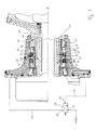
- FIG.1 a part of a rotary feedthrough in axial section.
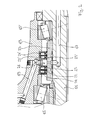
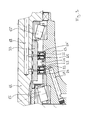
- FIG. 2 and 3 are detailed views of the upper part and the lower part of the Fig. 1 ,
- the rotary feedthrough shown comprises a wheel carrier with a steering knuckle 11, on which a wheel hub 13 is rotatably mounted with respect to a rotation axis A.
- This storage is accomplished via two rolling bearings 15, 15 ', which are designed here as tapered roller bearings.
- a compressed-air channel 17 is provided in the steering knuckle 11 (see the upper part of FIG Fig. 1 such as Fig. 2 ) connected to a compressed air source (not shown).
- This compressed air channel 17 communicates with a compressed air channel 19 of the wheel hub 13, which opens to a compressed air connection 27 of a valve 25, which is arranged on the relevant wheel, in particular on the wheel hub 13 or rim.
- the compressed air channels 17, 19 are via a compressed-air annular space 21 which is formed in the radial gap between the steering knuckle 11 and the hub 13, regardless of the rotational position of the hub 13 relative to the steering knuckle 11 and in principle also during rotation of the hub 13 with each other connected. In this way, compressed air from the compressed air source can be supplied to the valve 25 through the compressed air channels 17, 19 in order to increase the air pressure in the tire.
- a pressure drop in the tire is in corresponding manner possible, wherein the air from the tire is either supplied to the compressed air source (which of course presupposes a pressure gradient in the direction of the compressed air source) or is discharged into the environment (for which the valve 25, however, as a 3/2-way valve with a vent port and a vent channel in the wheel hub 13, not shown).
- the valve 25 shown is a controllable 2/2-way valve, which can optionally be blocked or controlled via a control connection 31, to let compressed air from the compressed air connection 27 to a working connection 29 (in the direction of the arrow) pass.
- the working port 29 is in communication with the interior of the tire, so that the tire with compressed air from the compressed air channels 17, 19 can be filled.
- the valve 25 is biased in a locking state.
- Axially adjacent to said compressed air annular space 21 for connecting the compressed air channels 17, 19 is on both sides of a respective lubricant annulus 22, 22 'is formed (see, the lower part of Fig. 1 such as Fig. 3 ), which is sealed off from the compressed-air annular space 21 by sealing rings 23, 23 '.
- the sealing rings 23, 23 ' are designed as radial shaft seals with an open front and a closed, extending in the radial direction back.
- Each of the radial shaft sealing rings 23, 23 ' is - based on the axial section shown - substantially "U" -shaped, wherein the open front side facing the respective lubricant annulus 22, 22'.
- the respective radial shaft sealing ring 23, 23 ' is connected to one leg of the "U" (a radially outer seat) on an inner circumferential surface of the wheel hub 13 non-positively and thus against rotation.
- the other leg of the "U” (a radially inner sealing surface) facing the steering knuckle 11 and is sealingly on a cylindrical running surface of an optional wear sleeve 33, which is firmly connected to the steering knuckle 11.
- a wear sleeve 33 has the advantage that not the entire wheel carrier must be replaced when the seal running surfaces have run, but that it is sufficient to replace only the wear sleeve 33. Furthermore, the wear sleeve 33 offers the advantage of easy machinability. Alternatively to the use of the wear sleeve 33, the radial shaft seals 23, 23 ', however, can also be arranged directly on the steering knuckle 11.
- a lubricant passage 18 which is directly or indirectly connected at one end to a source of lubricant (not shown, eg pump or pneumatic-hydraulic pressure converter within a substantially closed lubricant circuit).
- a source of lubricant not shown, eg pump or pneumatic-hydraulic pressure converter within a substantially closed lubricant circuit.
- the lubricant channel 18 communicates with the lubricant annular spaces 22, 22 'and supplies them with lubricant, such as lubricating oil.
- the pressure of the lubricant in the lubricant annular spaces 22, 22 ' can be adjusted in order to adapt the pressure force of the sealing rings 23, 23' to the wear sleeve 33.
- the pressure in the lubricant annular spaces 22, 22 ' can be temporarily increased, although the pressure in the compressed air annulus 21 is increased to fill the tire. In this way, one can adapt to the situation adapted reliable sealing of the compressed air annulus 21 can be achieved with minimal wear.
- a lubricant passage 20 is provided in the wheel hub 13, which communicates with one of the lubricant annular spaces 22, 22 ', so that the lubricant passage 18 of the steering knuckle 11 and the lubricant passage 20 of the wheel hub 13 via the lubricant annulus 22 are interconnected.
- the lubricant passage 20 of the wheel hub 13 opens to the control port 31 of the valve 25.
- control port 31 of the valve 25 may be directly connected to the lubricant channel 20 if it is suitable for directly evaluating the pressure of the lubricant in the lubricant channel 20 and converting it into a respective state of the valve 25.
- a pressure conversion device (not shown) may be provided by which the hydraulic pressure of the lubricant in the lubricant passage 20 is converted into a mechanical actuation of the control port 31 of the valve 25.
- the other lubricant annulus 22 at the same time also has a complementary function. Namely, lubricant can be transmitted to the lubricant passage 20 of the wheel hub 13 via this lubricant annulus 22, independently of the rotational position of the wheel hub 13 relative to the steering knuckle 11, on the same principle as in the compressed air annulus 21. so that the lubricant channels 18, 20 of the steering knuckle 11 and the wheel hub 13 communicate permanently via the lubricant annulus 22 with each other.
- the tire pressure control can indeed be carried out two-channel.
- a lubricant channel 20 is formed, of one of the sealing of the compressed air annulus 21st provided lubricant annular spaces 22, 22 'can be supplied with lubricant anyway.
- the lubricant used for the lubrication of the roller bearings 15, 15 ' is used for the control of the valve 25.
- the clearance formed between the wheel carrier 11 and the wheel hub 13 can deviate from the representation in the drawings, starting from the wheel carrier 11 to the wheel hub 13 in an axial direction, in which case the compressed air annulus 21 and the respective lubricant Annular space 22, 22 'are sealed in the radial direction against each other.
Landscapes
- Engineering & Computer Science (AREA)
- Mechanical Engineering (AREA)
- General Engineering & Computer Science (AREA)
- Rolling Contact Bearings (AREA)
Applications Claiming Priority (1)
| Application Number | Priority Date | Filing Date | Title |
|---|---|---|---|
| DE102014108028.9A DE102014108028B3 (de) | 2014-06-06 | 2014-06-06 | Drehdurchführung für ein Kraftfahrzeugrad |
Publications (3)
| Publication Number | Publication Date |
|---|---|
| EP2952365A2 true EP2952365A2 (fr) | 2015-12-09 |
| EP2952365A3 EP2952365A3 (fr) | 2016-01-06 |
| EP2952365B1 EP2952365B1 (fr) | 2016-12-14 |
Family
ID=53191576
Family Applications (1)
| Application Number | Title | Priority Date | Filing Date |
|---|---|---|---|
| EP15168971.8A Active EP2952365B1 (fr) | 2014-06-06 | 2015-05-22 | Passage tournant pour roue de véhicule |
Country Status (4)
| Country | Link |
|---|---|
| US (1) | US9499015B2 (fr) |
| EP (1) | EP2952365B1 (fr) |
| DE (1) | DE102014108028B3 (fr) |
| RU (1) | RU2669879C2 (fr) |
Cited By (3)
| Publication number | Priority date | Publication date | Assignee | Title |
|---|---|---|---|---|
| WO2017152996A1 (fr) * | 2016-03-11 | 2017-09-14 | Volvo Truck Corporation | Agencement de palier et procédé d'assemblage d'un agencement de palier à un moyeu |
| WO2019101686A1 (fr) * | 2017-11-21 | 2019-05-31 | Schaeffler Technologies AG & Co. KG | Ensemble d'étanchéité destiné à un passage tournant d'un palier de roue d'un véhicule automobile |
| CN110997354A (zh) * | 2017-07-27 | 2020-04-10 | 特雷勒堡车轮系统意大利股份公司 | 用于轮胎的旋转接头和压力调节系统 |
Families Citing this family (26)
| Publication number | Priority date | Publication date | Assignee | Title |
|---|---|---|---|---|
| EP2653323B1 (fr) * | 2012-04-19 | 2016-03-23 | DANA ITALIA S.p.A | Ensemble d'axe pour système de gonflage de pneus |
| US9452644B2 (en) * | 2013-09-18 | 2016-09-27 | Arvinmeritor Technology, Llc | Tire inflation system with a passage for routing pressurized gas |
| US9162539B2 (en) * | 2014-01-24 | 2015-10-20 | American Axle & Manufacturing, Inc. | Axle assembly having wheel hubs configured for use in vehicle with central tire inflation system |
| CA2954021A1 (fr) | 2014-07-02 | 2016-01-07 | Dana Italia S.P.A. | Joint rotatif pour un systeme central de gonflage de pneumatiques |
| US9511635B2 (en) * | 2014-07-10 | 2016-12-06 | Airgo Ip, Llc | Apparatus for delivering air through powered axle assemblies |
| EP3201013B1 (fr) * | 2014-10-01 | 2018-08-29 | Bayerische Motoren Werke Aktiengesellschaft | Système et procédé d'alimentation en air comprimé d'une roue d'un véhicule |
| EP3208118A1 (fr) * | 2016-02-19 | 2017-08-23 | DANA ITALIA S.r.l. | Ensemble de traversée rotative pour un système de gonflage de pneu |
| US11254170B2 (en) * | 2017-04-13 | 2022-02-22 | Tesla, Inc. | Automatic tire inflation system with thru-hub air feed |
| PL3401129T3 (pl) | 2017-05-12 | 2019-12-31 | Reinhold Schulte | Urządzenie do zapewniania ciśnienia w oponach |
| US11560015B2 (en) | 2017-09-22 | 2023-01-24 | Consolidated Metco, Inc. | Wheel hub |
| MX2020005382A (es) * | 2017-10-05 | 2020-10-19 | Stemco Products Inc | Espaciador para mejorar la lubricacion del ensamble del extremo de la rueda. |
| WO2020106942A1 (fr) * | 2018-11-21 | 2020-05-28 | Consolidated Metco, Inc. | Appareil d'extrémité de roue comprenant un générateur électrique |
| US11454322B2 (en) | 2019-06-04 | 2022-09-27 | Fairfield Manufacturing Company, Inc. | Rotary pneumatic seal for a central tire inflation system |
| US20210031571A1 (en) * | 2019-07-31 | 2021-02-04 | Polaris Industries Inc. | Central Tire Deflation/Inflation System |
| WO2021072110A1 (fr) | 2019-10-09 | 2021-04-15 | Consolidated Metco, Inc. | Appareil de surveillance d'extrémité de roue, élément de fixation, et procédé |
| DE102020104042B3 (de) * | 2020-02-17 | 2021-07-22 | Schaeffler Technologies AG & Co. KG | Radlager zur Lagerung eines Kraftfahrzeugreifens eines Kraftfahrzeugs |
| WO2021212119A1 (fr) | 2020-04-17 | 2021-10-21 | Irh Inc. | Système et dispositif de moyeu de gonflage de pneu intégré modulaire |
| DE102020111517A1 (de) * | 2020-04-28 | 2021-10-28 | Dr. Ing. H.C. F. Porsche Aktiengesellschaft | Radträgeranordnung einer Vorderachse bzw. Hinterachse eines Kraftfahrzeuges |
| US11718127B2 (en) * | 2020-05-20 | 2023-08-08 | Arvinmeritor Technology, Llc | Axle assembly with internal lubrication system |
| US11865873B2 (en) * | 2021-01-21 | 2024-01-09 | Arvinmeritor Technology, Llc | Wheel end assembly having an annular hub chamber |
| US11117426B1 (en) * | 2021-03-24 | 2021-09-14 | Ptg Reifendruckregelsysteme Gmbh | Rotary transmission leadthrough as part of a tire pressure control system |
| FR3123403B1 (fr) * | 2021-05-31 | 2023-06-02 | Sodijantes Ind | Ensemble d’étanchéité, système de télégonflage et véhicule automobile associés |
| AU2023324834A1 (en) * | 2022-08-19 | 2025-02-27 | Consolidated Metco, Inc. | Wheel hub with passageway |
| US20240399800A1 (en) * | 2023-06-05 | 2024-12-05 | Cnh Industrial America Llc | Continuous Tire Inflation System Implementation |
| DE102023206643A1 (de) * | 2023-07-13 | 2025-01-16 | Zf Friedrichshafen Ag | Reifendruckregelvorrichtung, landwirtschaftliches Nutzfahrzeug und Baumaschine |
| CN116901623B (zh) * | 2023-08-30 | 2026-04-21 | 东风汽车有限公司东风日产乘用车公司 | 胎压调节系统及方法、存储介质和电子设备 |
Citations (1)
| Publication number | Priority date | Publication date | Assignee | Title |
|---|---|---|---|---|
| DE102009057158A1 (de) | 2009-12-05 | 2011-06-09 | Kessler & Co. Gmbh & Co. Kg | Drehdurchführung |
Family Cites Families (14)
| Publication number | Priority date | Publication date | Assignee | Title |
|---|---|---|---|---|
| DE827605C (de) * | 1950-04-15 | 1952-01-10 | Erwin Krauskopf | Anordnung an mit Luftreifen versehenen Fahrzeugraedern |
| DE8705739U1 (de) * | 1987-04-18 | 1987-08-20 | Brock, Thomas, 8969 Dietmannsried | Reifendruckregelvorrichtung für Kraftfahrzeuge, insbesondere für Ackerschlepper |
| US4892128A (en) * | 1987-08-28 | 1990-01-09 | Tire Inflation Systems Corp. | Vehicle wheel seal assembly |
| JPH0726164Y2 (ja) * | 1989-07-28 | 1995-06-14 | 日産自動車株式会社 | タイヤ空気圧調整装置用シール装置 |
| US6145558A (en) * | 1998-12-10 | 2000-11-14 | Case Corporation | Seal arrangement for a central tire inflation system |
| AT3682U1 (de) * | 1999-01-13 | 2000-06-26 | Steyr Daimler Puch Ag | Anordnung mit konzentrisch zueinander angeordneten und relativ zueinander rotierbaren bauteilen und verwendung dieser anordnung bei einer reifenfüllanlage |
| DE102006006143A1 (de) * | 2006-02-10 | 2007-08-23 | Schaeffler Kg | Dichtungsanordnung für eine Reifendruck-Reguliereinrichtung |
| US8915274B2 (en) * | 2009-01-22 | 2014-12-23 | Arvinmeritor Technology, Llc | Spindle for controlling wheel end endplay and preload |
| GB201021931D0 (en) * | 2010-12-23 | 2011-02-02 | Agco Int Gmbh | Rotary seal arrangement |
| EP2653323B1 (fr) * | 2012-04-19 | 2016-03-23 | DANA ITALIA S.p.A | Ensemble d'axe pour système de gonflage de pneus |
| AU2013336975B2 (en) * | 2012-10-26 | 2017-06-29 | Gv Engineering Gmbh | Vehicle axle assembly comprising integrated pressure medium line for filling tyres |
| DE102013205399A1 (de) * | 2013-03-27 | 2014-10-02 | Robert Bosch Gmbh | Radnabenantrieb mit einem Planetengetriebe |
| DE102013013509A1 (de) * | 2013-08-16 | 2015-02-19 | Claas Tractor S.A.S. | Radaufhängung |
| US9162539B2 (en) * | 2014-01-24 | 2015-10-20 | American Axle & Manufacturing, Inc. | Axle assembly having wheel hubs configured for use in vehicle with central tire inflation system |
-
2014
- 2014-06-06 DE DE102014108028.9A patent/DE102014108028B3/de not_active Expired - Fee Related
-
2015
- 2015-05-22 EP EP15168971.8A patent/EP2952365B1/fr active Active
- 2015-06-01 US US14/726,912 patent/US9499015B2/en active Active
- 2015-06-05 RU RU2015121689A patent/RU2669879C2/ru active
Patent Citations (1)
| Publication number | Priority date | Publication date | Assignee | Title |
|---|---|---|---|---|
| DE102009057158A1 (de) | 2009-12-05 | 2011-06-09 | Kessler & Co. Gmbh & Co. Kg | Drehdurchführung |
Cited By (3)
| Publication number | Priority date | Publication date | Assignee | Title |
|---|---|---|---|---|
| WO2017152996A1 (fr) * | 2016-03-11 | 2017-09-14 | Volvo Truck Corporation | Agencement de palier et procédé d'assemblage d'un agencement de palier à un moyeu |
| CN110997354A (zh) * | 2017-07-27 | 2020-04-10 | 特雷勒堡车轮系统意大利股份公司 | 用于轮胎的旋转接头和压力调节系统 |
| WO2019101686A1 (fr) * | 2017-11-21 | 2019-05-31 | Schaeffler Technologies AG & Co. KG | Ensemble d'étanchéité destiné à un passage tournant d'un palier de roue d'un véhicule automobile |
Also Published As
| Publication number | Publication date |
|---|---|
| RU2015121689A3 (fr) | 2018-08-30 |
| EP2952365B1 (fr) | 2016-12-14 |
| EP2952365A3 (fr) | 2016-01-06 |
| RU2669879C2 (ru) | 2018-10-16 |
| US20150352911A1 (en) | 2015-12-10 |
| DE102014108028B3 (de) | 2015-09-24 |
| US9499015B2 (en) | 2016-11-22 |
| RU2015121689A (ru) | 2016-12-27 |
Similar Documents
| Publication | Publication Date | Title |
|---|---|---|
| EP2952365B1 (fr) | Passage tournant pour roue de véhicule | |
| DE19921750B4 (de) | Getriebe | |
| DE3513582C2 (de) | Proportional arbeitendes Hydroventil mit Informationserfassung betreffend die stärksten Drücke in den Verbraucherkreisen | |
| EP3058250A2 (fr) | Dispositif de commande hydraulique pour transmission automatique | |
| EP2486280B1 (fr) | Pompe volumétrique rotative à palettes | |
| EP1212517B1 (fr) | Dispositif de reglage d'un arbre a cames destine a des moteurs a combustion interne | |
| EP3047183B1 (fr) | Dispositif de commande pour effectuer sélectivement une connexion fluidique et une déconnexion de points de raccordement fluidique | |
| DE102006014737A1 (de) | Vorrichtung zur Betätigung einer Lamellenkupplung in einem Getriebe | |
| WO2012130466A1 (fr) | Dispositif pneumatique d'assistance de force de changement de rapport | |
| DE2236257C3 (de) | Reibungsgetriebe mit veränderlicher Übersetzung | |
| DE60029425T2 (de) | Motor mit symmetrischem bremssystem | |
| DE19504451B4 (de) | Antriebseinrichtung für mobile Arbeitsgeräte | |
| EP1654136A1 (fr) | Systeme d'entrainement hydrostatique avec separation de masse de liquide hydraulique cote pompe, pour deux circuits hydrauliques | |
| DE102015213692A1 (de) | Radnabenantrieb | |
| DE4442117C2 (de) | Steuerbare Differentialsperre | |
| DE102004041776A1 (de) | Vorrichtung zum wahlweisen Aus- bzw. Einrücken einer Reibkupplung für Kraftfahrzeuge | |
| DE102014102633A1 (de) | Drehdurchführung für ein Kraftfahrzeugrad | |
| DE2236290C3 (de) | Hydraulische Schalteinrichtung für Schwenkrollengetriebe | |
| DE112013004343T5 (de) | Steuerzylinder für ein Getriebe, Getriebe mit einem solchen Steuerzylinder und Fahrzeug mit einem solchen Getriebe | |
| DE102018000171A1 (de) | Kupplungsvorrichtung | |
| DE102015015858A1 (de) | Überwachungseinrichtung für Werkzeugrevolver | |
| DE2833178C2 (de) | Hydraulisches Tandem-Bremsdruckmindererventil | |
| DE1673369A1 (de) | Hydraulischer Fliehkraftregler | |
| EP3450239A1 (fr) | Engrenage, en particulier pour un une unité d'entraînement à roue indépendante | |
| EP4013973B1 (fr) | Système de transmission de puissance |
Legal Events
| Date | Code | Title | Description |
|---|---|---|---|
| PUAL | Search report despatched |
Free format text: ORIGINAL CODE: 0009013 |
|
| PUAI | Public reference made under article 153(3) epc to a published international application that has entered the european phase |
Free format text: ORIGINAL CODE: 0009012 |
|
| AK | Designated contracting states |
Kind code of ref document: A2 Designated state(s): AL AT BE BG CH CY CZ DE DK EE ES FI FR GB GR HR HU IE IS IT LI LT LU LV MC MK MT NL NO PL PT RO RS SE SI SK SM TR |
|
| AX | Request for extension of the european patent |
Extension state: BA ME |
|
| AK | Designated contracting states |
Kind code of ref document: A3 Designated state(s): AL AT BE BG CH CY CZ DE DK EE ES FI FR GB GR HR HU IE IS IT LI LT LU LV MC MK MT NL NO PL PT RO RS SE SI SK SM TR |
|
| AX | Request for extension of the european patent |
Extension state: BA ME |
|
| RIC1 | Information provided on ipc code assigned before grant |
Ipc: B60B 27/00 20060101ALN20151130BHEP Ipc: B60C 23/00 20060101AFI20151130BHEP |
|
| 17P | Request for examination filed |
Effective date: 20160304 |
|
| RBV | Designated contracting states (corrected) |
Designated state(s): AL AT BE BG CH CY CZ DE DK EE ES FI FR GB GR HR HU IE IS IT LI LT LU LV MC MK MT NL NO PL PT RO RS SE SI SK SM TR |
|
| RIC1 | Information provided on ipc code assigned before grant |
Ipc: B60B 27/00 20060101ALN20160711BHEP Ipc: B60C 23/00 20060101AFI20160711BHEP Ipc: F16L 27/087 20060101ALI20160711BHEP |
|
| GRAP | Despatch of communication of intention to grant a patent |
Free format text: ORIGINAL CODE: EPIDOSNIGR1 |
|
| INTG | Intention to grant announced |
Effective date: 20160826 |
|
| GRAS | Grant fee paid |
Free format text: ORIGINAL CODE: EPIDOSNIGR3 |
|
| STAA | Information on the status of an ep patent application or granted ep patent |
Free format text: STATUS: GRANT OF PATENT IS INTENDED |
|
| GRAA | (expected) grant |
Free format text: ORIGINAL CODE: 0009210 |
|
| STAA | Information on the status of an ep patent application or granted ep patent |
Free format text: STATUS: THE PATENT HAS BEEN GRANTED |
|
| AK | Designated contracting states |
Kind code of ref document: B1 Designated state(s): AL AT BE BG CH CY CZ DE DK EE ES FI FR GB GR HR HU IE IS IT LI LT LU LV MC MK MT NL NO PL PT RO RS SE SI SK SM TR |
|
| REG | Reference to a national code |
Ref country code: GB Ref legal event code: FG4D Free format text: NOT ENGLISH |
|
| REG | Reference to a national code |
Ref country code: CH Ref legal event code: EP |
|
| REG | Reference to a national code |
Ref country code: IE Ref legal event code: FG4D Free format text: LANGUAGE OF EP DOCUMENT: GERMAN |
|
| REG | Reference to a national code |
Ref country code: AT Ref legal event code: REF Ref document number: 853224 Country of ref document: AT Kind code of ref document: T Effective date: 20170115 |
|
| REG | Reference to a national code |
Ref country code: DE Ref legal event code: R096 Ref document number: 502015000393 Country of ref document: DE |
|
| PG25 | Lapsed in a contracting state [announced via postgrant information from national office to epo] |
Ref country code: LV Free format text: LAPSE BECAUSE OF FAILURE TO SUBMIT A TRANSLATION OF THE DESCRIPTION OR TO PAY THE FEE WITHIN THE PRESCRIBED TIME-LIMIT Effective date: 20161214 |
|
| REG | Reference to a national code |
Ref country code: LT Ref legal event code: MG4D |
|
| REG | Reference to a national code |
Ref country code: NL Ref legal event code: MP Effective date: 20161214 |
|
| PG25 | Lapsed in a contracting state [announced via postgrant information from national office to epo] |
Ref country code: GR Free format text: LAPSE BECAUSE OF FAILURE TO SUBMIT A TRANSLATION OF THE DESCRIPTION OR TO PAY THE FEE WITHIN THE PRESCRIBED TIME-LIMIT Effective date: 20170315 Ref country code: LT Free format text: LAPSE BECAUSE OF FAILURE TO SUBMIT A TRANSLATION OF THE DESCRIPTION OR TO PAY THE FEE WITHIN THE PRESCRIBED TIME-LIMIT Effective date: 20161214 Ref country code: NO Free format text: LAPSE BECAUSE OF FAILURE TO SUBMIT A TRANSLATION OF THE DESCRIPTION OR TO PAY THE FEE WITHIN THE PRESCRIBED TIME-LIMIT Effective date: 20170314 Ref country code: SE Free format text: LAPSE BECAUSE OF FAILURE TO SUBMIT A TRANSLATION OF THE DESCRIPTION OR TO PAY THE FEE WITHIN THE PRESCRIBED TIME-LIMIT Effective date: 20161214 |
|
| REG | Reference to a national code |
Ref country code: FR Ref legal event code: PLFP Year of fee payment: 3 |
|
| PG25 | Lapsed in a contracting state [announced via postgrant information from national office to epo] |
Ref country code: RS Free format text: LAPSE BECAUSE OF FAILURE TO SUBMIT A TRANSLATION OF THE DESCRIPTION OR TO PAY THE FEE WITHIN THE PRESCRIBED TIME-LIMIT Effective date: 20161214 Ref country code: FI Free format text: LAPSE BECAUSE OF FAILURE TO SUBMIT A TRANSLATION OF THE DESCRIPTION OR TO PAY THE FEE WITHIN THE PRESCRIBED TIME-LIMIT Effective date: 20161214 Ref country code: HR Free format text: LAPSE BECAUSE OF FAILURE TO SUBMIT A TRANSLATION OF THE DESCRIPTION OR TO PAY THE FEE WITHIN THE PRESCRIBED TIME-LIMIT Effective date: 20161214 |
|
| PG25 | Lapsed in a contracting state [announced via postgrant information from national office to epo] |
Ref country code: NL Free format text: LAPSE BECAUSE OF FAILURE TO SUBMIT A TRANSLATION OF THE DESCRIPTION OR TO PAY THE FEE WITHIN THE PRESCRIBED TIME-LIMIT Effective date: 20161214 |
|
| PG25 | Lapsed in a contracting state [announced via postgrant information from national office to epo] |
Ref country code: IS Free format text: LAPSE BECAUSE OF FAILURE TO SUBMIT A TRANSLATION OF THE DESCRIPTION OR TO PAY THE FEE WITHIN THE PRESCRIBED TIME-LIMIT Effective date: 20170414 Ref country code: RO Free format text: LAPSE BECAUSE OF FAILURE TO SUBMIT A TRANSLATION OF THE DESCRIPTION OR TO PAY THE FEE WITHIN THE PRESCRIBED TIME-LIMIT Effective date: 20161214 Ref country code: EE Free format text: LAPSE BECAUSE OF FAILURE TO SUBMIT A TRANSLATION OF THE DESCRIPTION OR TO PAY THE FEE WITHIN THE PRESCRIBED TIME-LIMIT Effective date: 20161214 Ref country code: SK Free format text: LAPSE BECAUSE OF FAILURE TO SUBMIT A TRANSLATION OF THE DESCRIPTION OR TO PAY THE FEE WITHIN THE PRESCRIBED TIME-LIMIT Effective date: 20161214 Ref country code: CZ Free format text: LAPSE BECAUSE OF FAILURE TO SUBMIT A TRANSLATION OF THE DESCRIPTION OR TO PAY THE FEE WITHIN THE PRESCRIBED TIME-LIMIT Effective date: 20161214 |
|
| PG25 | Lapsed in a contracting state [announced via postgrant information from national office to epo] |
Ref country code: BG Free format text: LAPSE BECAUSE OF FAILURE TO SUBMIT A TRANSLATION OF THE DESCRIPTION OR TO PAY THE FEE WITHIN THE PRESCRIBED TIME-LIMIT Effective date: 20170314 Ref country code: SM Free format text: LAPSE BECAUSE OF FAILURE TO SUBMIT A TRANSLATION OF THE DESCRIPTION OR TO PAY THE FEE WITHIN THE PRESCRIBED TIME-LIMIT Effective date: 20161214 Ref country code: IT Free format text: LAPSE BECAUSE OF FAILURE TO SUBMIT A TRANSLATION OF THE DESCRIPTION OR TO PAY THE FEE WITHIN THE PRESCRIBED TIME-LIMIT Effective date: 20161214 Ref country code: PT Free format text: LAPSE BECAUSE OF FAILURE TO SUBMIT A TRANSLATION OF THE DESCRIPTION OR TO PAY THE FEE WITHIN THE PRESCRIBED TIME-LIMIT Effective date: 20170414 Ref country code: ES Free format text: LAPSE BECAUSE OF FAILURE TO SUBMIT A TRANSLATION OF THE DESCRIPTION OR TO PAY THE FEE WITHIN THE PRESCRIBED TIME-LIMIT Effective date: 20161214 Ref country code: LU Free format text: LAPSE BECAUSE OF NON-PAYMENT OF DUE FEES Effective date: 20170531 Ref country code: PL Free format text: LAPSE BECAUSE OF FAILURE TO SUBMIT A TRANSLATION OF THE DESCRIPTION OR TO PAY THE FEE WITHIN THE PRESCRIBED TIME-LIMIT Effective date: 20161214 |
|
| REG | Reference to a national code |
Ref country code: DE Ref legal event code: R097 Ref document number: 502015000393 Country of ref document: DE |
|
| PLBE | No opposition filed within time limit |
Free format text: ORIGINAL CODE: 0009261 |
|
| STAA | Information on the status of an ep patent application or granted ep patent |
Free format text: STATUS: NO OPPOSITION FILED WITHIN TIME LIMIT |
|
| 26N | No opposition filed |
Effective date: 20170915 |
|
| PG25 | Lapsed in a contracting state [announced via postgrant information from national office to epo] |
Ref country code: DK Free format text: LAPSE BECAUSE OF FAILURE TO SUBMIT A TRANSLATION OF THE DESCRIPTION OR TO PAY THE FEE WITHIN THE PRESCRIBED TIME-LIMIT Effective date: 20161214 |
|
| PG25 | Lapsed in a contracting state [announced via postgrant information from national office to epo] |
Ref country code: MC Free format text: LAPSE BECAUSE OF FAILURE TO SUBMIT A TRANSLATION OF THE DESCRIPTION OR TO PAY THE FEE WITHIN THE PRESCRIBED TIME-LIMIT Effective date: 20161214 |
|
| REG | Reference to a national code |
Ref country code: IE Ref legal event code: MM4A |
|
| PG25 | Lapsed in a contracting state [announced via postgrant information from national office to epo] |
Ref country code: SI Free format text: LAPSE BECAUSE OF FAILURE TO SUBMIT A TRANSLATION OF THE DESCRIPTION OR TO PAY THE FEE WITHIN THE PRESCRIBED TIME-LIMIT Effective date: 20161214 |
|
| PG25 | Lapsed in a contracting state [announced via postgrant information from national office to epo] |
Ref country code: LU Free format text: LAPSE BECAUSE OF NON-PAYMENT OF DUE FEES Effective date: 20170522 |
|
| REG | Reference to a national code |
Ref country code: BE Ref legal event code: MM Effective date: 20170531 |
|
| PG25 | Lapsed in a contracting state [announced via postgrant information from national office to epo] |
Ref country code: IE Free format text: LAPSE BECAUSE OF NON-PAYMENT OF DUE FEES Effective date: 20170522 |
|
| REG | Reference to a national code |
Ref country code: FR Ref legal event code: PLFP Year of fee payment: 4 |
|
| PG25 | Lapsed in a contracting state [announced via postgrant information from national office to epo] |
Ref country code: BE Free format text: LAPSE BECAUSE OF NON-PAYMENT OF DUE FEES Effective date: 20170531 |
|
| PG25 | Lapsed in a contracting state [announced via postgrant information from national office to epo] |
Ref country code: MT Free format text: LAPSE BECAUSE OF FAILURE TO SUBMIT A TRANSLATION OF THE DESCRIPTION OR TO PAY THE FEE WITHIN THE PRESCRIBED TIME-LIMIT Effective date: 20161214 |
|
| REG | Reference to a national code |
Ref country code: CH Ref legal event code: PL |
|
| PG25 | Lapsed in a contracting state [announced via postgrant information from national office to epo] |
Ref country code: CH Free format text: LAPSE BECAUSE OF NON-PAYMENT OF DUE FEES Effective date: 20180531 Ref country code: LI Free format text: LAPSE BECAUSE OF NON-PAYMENT OF DUE FEES Effective date: 20180531 |
|
| PG25 | Lapsed in a contracting state [announced via postgrant information from national office to epo] |
Ref country code: HU Free format text: LAPSE BECAUSE OF FAILURE TO SUBMIT A TRANSLATION OF THE DESCRIPTION OR TO PAY THE FEE WITHIN THE PRESCRIBED TIME-LIMIT; INVALID AB INITIO Effective date: 20150522 |
|
| PG25 | Lapsed in a contracting state [announced via postgrant information from national office to epo] |
Ref country code: CY Free format text: LAPSE BECAUSE OF FAILURE TO SUBMIT A TRANSLATION OF THE DESCRIPTION OR TO PAY THE FEE WITHIN THE PRESCRIBED TIME-LIMIT Effective date: 20161214 |
|
| PG25 | Lapsed in a contracting state [announced via postgrant information from national office to epo] |
Ref country code: MK Free format text: LAPSE BECAUSE OF FAILURE TO SUBMIT A TRANSLATION OF THE DESCRIPTION OR TO PAY THE FEE WITHIN THE PRESCRIBED TIME-LIMIT Effective date: 20161214 |
|
| PG25 | Lapsed in a contracting state [announced via postgrant information from national office to epo] |
Ref country code: TR Free format text: LAPSE BECAUSE OF FAILURE TO SUBMIT A TRANSLATION OF THE DESCRIPTION OR TO PAY THE FEE WITHIN THE PRESCRIBED TIME-LIMIT Effective date: 20161214 |
|
| PG25 | Lapsed in a contracting state [announced via postgrant information from national office to epo] |
Ref country code: AL Free format text: LAPSE BECAUSE OF FAILURE TO SUBMIT A TRANSLATION OF THE DESCRIPTION OR TO PAY THE FEE WITHIN THE PRESCRIBED TIME-LIMIT Effective date: 20161214 |
|
| REG | Reference to a national code |
Ref country code: AT Ref legal event code: MM01 Ref document number: 853224 Country of ref document: AT Kind code of ref document: T Effective date: 20200522 |
|
| PG25 | Lapsed in a contracting state [announced via postgrant information from national office to epo] |
Ref country code: AT Free format text: LAPSE BECAUSE OF NON-PAYMENT OF DUE FEES Effective date: 20200522 |
|
| PGFP | Annual fee paid to national office [announced via postgrant information from national office to epo] |
Ref country code: GB Payment date: 20250527 Year of fee payment: 11 |
|
| PGFP | Annual fee paid to national office [announced via postgrant information from national office to epo] |
Ref country code: FR Payment date: 20250528 Year of fee payment: 11 |
|
| PGFP | Annual fee paid to national office [announced via postgrant information from national office to epo] |
Ref country code: DE Payment date: 20250729 Year of fee payment: 11 |