EP3201013B1 - Système et procédé d'alimentation en air comprimé d'une roue d'un véhicule - Google Patents
Système et procédé d'alimentation en air comprimé d'une roue d'un véhicule Download PDFInfo
- Publication number
- EP3201013B1 EP3201013B1 EP15756661.3A EP15756661A EP3201013B1 EP 3201013 B1 EP3201013 B1 EP 3201013B1 EP 15756661 A EP15756661 A EP 15756661A EP 3201013 B1 EP3201013 B1 EP 3201013B1
- Authority
- EP
- European Patent Office
- Prior art keywords
- compressed air
- wheel
- wheel bearing
- annular space
- screw
- Prior art date
- Legal status (The legal status is an assumption and is not a legal conclusion. Google has not performed a legal analysis and makes no representation as to the accuracy of the status listed.)
- Active
Links
Images




Classifications
-
- B—PERFORMING OPERATIONS; TRANSPORTING
- B60—VEHICLES IN GENERAL
- B60B—VEHICLE WHEELS; CASTORS; AXLES FOR WHEELS OR CASTORS; INCREASING WHEEL ADHESION
- B60B27/00—Hubs
- B60B27/0047—Hubs characterised by functional integration of other elements
-
- B—PERFORMING OPERATIONS; TRANSPORTING
- B60—VEHICLES IN GENERAL
- B60C—VEHICLE TYRES; TYRE INFLATION; TYRE CHANGING; CONNECTING VALVES TO INFLATABLE ELASTIC BODIES IN GENERAL; DEVICES OR ARRANGEMENTS RELATED TO TYRES
- B60C23/00—Devices for measuring, signalling, controlling, or distributing tyre pressure or temperature, specially adapted for mounting on vehicles; Arrangement of tyre inflating devices on vehicles, e.g. of pumps or of tanks; Tyre cooling arrangements
- B60C23/001—Devices for manually or automatically controlling or distributing tyre pressure whilst the vehicle is moving
- B60C23/003—Devices for manually or automatically controlling or distributing tyre pressure whilst the vehicle is moving comprising rotational joints between vehicle-mounted pressure sources and the tyres
- B60C23/00345—Details of the rotational joints
-
- B—PERFORMING OPERATIONS; TRANSPORTING
- B60—VEHICLES IN GENERAL
- B60C—VEHICLE TYRES; TYRE INFLATION; TYRE CHANGING; CONNECTING VALVES TO INFLATABLE ELASTIC BODIES IN GENERAL; DEVICES OR ARRANGEMENTS RELATED TO TYRES
- B60C23/00—Devices for measuring, signalling, controlling, or distributing tyre pressure or temperature, specially adapted for mounting on vehicles; Arrangement of tyre inflating devices on vehicles, e.g. of pumps or of tanks; Tyre cooling arrangements
- B60C23/001—Devices for manually or automatically controlling or distributing tyre pressure whilst the vehicle is moving
- B60C23/003—Devices for manually or automatically controlling or distributing tyre pressure whilst the vehicle is moving comprising rotational joints between vehicle-mounted pressure sources and the tyres
- B60C23/00354—Details of valves
-
- B—PERFORMING OPERATIONS; TRANSPORTING
- B60—VEHICLES IN GENERAL
- B60C—VEHICLE TYRES; TYRE INFLATION; TYRE CHANGING; CONNECTING VALVES TO INFLATABLE ELASTIC BODIES IN GENERAL; DEVICES OR ARRANGEMENTS RELATED TO TYRES
- B60C23/00—Devices for measuring, signalling, controlling, or distributing tyre pressure or temperature, specially adapted for mounting on vehicles; Arrangement of tyre inflating devices on vehicles, e.g. of pumps or of tanks; Tyre cooling arrangements
- B60C23/001—Devices for manually or automatically controlling or distributing tyre pressure whilst the vehicle is moving
- B60C23/003—Devices for manually or automatically controlling or distributing tyre pressure whilst the vehicle is moving comprising rotational joints between vehicle-mounted pressure sources and the tyres
- B60C23/00363—Details of sealings
-
- B—PERFORMING OPERATIONS; TRANSPORTING
- B60—VEHICLES IN GENERAL
- B60C—VEHICLE TYRES; TYRE INFLATION; TYRE CHANGING; CONNECTING VALVES TO INFLATABLE ELASTIC BODIES IN GENERAL; DEVICES OR ARRANGEMENTS RELATED TO TYRES
- B60C23/00—Devices for measuring, signalling, controlling, or distributing tyre pressure or temperature, specially adapted for mounting on vehicles; Arrangement of tyre inflating devices on vehicles, e.g. of pumps or of tanks; Tyre cooling arrangements
- B60C23/001—Devices for manually or automatically controlling or distributing tyre pressure whilst the vehicle is moving
- B60C23/003—Devices for manually or automatically controlling or distributing tyre pressure whilst the vehicle is moving comprising rotational joints between vehicle-mounted pressure sources and the tyres
- B60C23/00372—Devices for manually or automatically controlling or distributing tyre pressure whilst the vehicle is moving comprising rotational joints between vehicle-mounted pressure sources and the tyres characterised by fluid diagrams
-
- B—PERFORMING OPERATIONS; TRANSPORTING
- B60—VEHICLES IN GENERAL
- B60C—VEHICLE TYRES; TYRE INFLATION; TYRE CHANGING; CONNECTING VALVES TO INFLATABLE ELASTIC BODIES IN GENERAL; DEVICES OR ARRANGEMENTS RELATED TO TYRES
- B60C23/00—Devices for measuring, signalling, controlling, or distributing tyre pressure or temperature, specially adapted for mounting on vehicles; Arrangement of tyre inflating devices on vehicles, e.g. of pumps or of tanks; Tyre cooling arrangements
- B60C23/001—Devices for manually or automatically controlling or distributing tyre pressure whilst the vehicle is moving
- B60C23/003—Devices for manually or automatically controlling or distributing tyre pressure whilst the vehicle is moving comprising rotational joints between vehicle-mounted pressure sources and the tyres
- B60C23/0039—Devices for manually or automatically controlling or distributing tyre pressure whilst the vehicle is moving comprising rotational joints between vehicle-mounted pressure sources and the tyres specially adapted for driven wheels
-
- B—PERFORMING OPERATIONS; TRANSPORTING
- B60—VEHICLES IN GENERAL
- B60B—VEHICLE WHEELS; CASTORS; AXLES FOR WHEELS OR CASTORS; INCREASING WHEEL ADHESION
- B60B27/00—Hubs
- B60B27/0005—Hubs with ball bearings
Definitions
- the present invention relates to an arrangement for supplying compressed air to a wheel of a vehicle, in particular of a motor vehicle.
- an arrangement for supplying compressed air to a wheel of a vehicle in particular of a motor vehicle.
- Changing the tire pressure in a vehicle can have both a positive effect on ride comfort and energy consumption.
- a correspondingly low tire pressure for example, leads to a soft suspension in the tire and thus to a more comfortable ride.
- a correspondingly high tire pressure reduces the rolling resistance. This in turn reduces the energy consumption of the vehicle and thereby improves the CO2 balance.
- the problem with the construction of the compressed air supply is always the compressed air supply from the compressed air source in the vehicle to the rotating wheel US 2008/0006357 A1 shows an exemplary solution. The air is guided through appropriate holes and lines in the suspension.
- FR 2 731 655 A1 shows a system for air pressure regulation in a vehicle tire by means of a compressed air source and a plurality of valves, wherein the compressed air is passed through a wheel bearing either in the tire or out of this.
- a valve which can switch the supply or discharge of air into and out of the tire in a particularly simple manner, shows the FR 2 896 725 A1 ,
- the object is achieved by an arrangement for supplying compressed air to a wheel of a vehicle.
- the arrangement includes a wheel with tires and an output shaft.
- the output shaft is used for torque transmission to the wheel. Accordingly, the output shaft of the engine of the vehicle over any gearbox leads to the suspension.
- the wheel On a wheel bearing of the arrangement, the wheel is rotatably mounted. Between the output shaft and the wheel bearing a toothing is provided. This gearing is used for torque transmission from the output shaft to the wheel bearing.
- the wheel bearing is clamped by means of a screw with the output shaft. This screw extends coaxially to the output shaft in an inner cavity of the wheel bearing. In this cavity, radially outside the screw, a so-called Radlagerringraum is defined.
- at least one compressed air passage is provided by this wheel bearing annulus in the direction of the wheel.
- the arrangement comprises a compressed air guide. This leads from a vehicle-side compressed air source in the Radlagerringraum and the Radlagerringraum by the at least one compressed air passage to the wheel.
- the compressed air can be guided radially outward, for example through the spokes, to the rim and in the tire.
- the invention is therefore intended to use the Radlagerringraum in the compressed air supply.
- At least the one compressed air passage is provided in order to guide the introduced into the Radlagerringraum compressed air in the direction of the wheel.
- a screw head of the screw bears against a bearing surface on the wheel bearing.
- the at least one compressed air passage is formed in the region of the bearing surface and / or in the wheel bearing and / or in the screw. In order to direct the compressed air from the wheel bearing annulus further in the direction of the wheel, the compressed air must be passed through the support surface or near the support surface (ie in the wheel bearing) or through the screw.
- the at least one compressed air passage will be described. It is always understood that several of the compressed air passages can be formed in one arrangement. It is also possible that the multiple compressed air passages are designed differently. For example, there may be a compressed air passage as a groove and another compressed air passage as a channel.
- the compressed air passage is formed by a groove in the wheel bearing on the support surface and / or by a groove in the screw head on the support surface.
- the channel is preferably formed as a bore.
- a corresponding tube during casting of the wheel bearing and to encapsulate.
- the channels are formed as short as possible and only lead around the bearing surface, so that a weakening of the corresponding components is avoided as far as possible.
- It can be designed a channel that passes only through the screw head.
- a first channel may be along the central axis extend the screw. A radially directed lateral channel meets this first channel.
- the radially directed channel extends through the entire screw and is therefore easy to manufacture.
- a washer on the support surface.
- this washer at least one groove or a bore or a corresponding recess is formed. The compressed air can be passed through the groove, bore or recess in the washer from the Radlagerringraum in the direction of the wheel.
- a spring ring can be arranged on the support surface.
- the corresponding waveform of the spring ring allows the formation of a compressed air passage.
- the screw is not tightened so far that the spring ring over its entire surface fully rests and seals.
- the washer or the spring ring can also be used as a non-closed ring, z. B. in C-shape, be formed, wherein the open portion forms the recess for the compressed air.
- an air-permeable, for example porous, material for forming the compressed-air passage.
- This air-permeable material is used as part of the wheel bearing and / or as at least part of the screw or as at least a part of the washer.
- sintered metal, metal foam or porous PTFE foam polytetrafluoroethylene
- Metapor material can be used here as an air-permeable material.
- the output shaft is connected via a toothing with the wheel bearing. It has been recognized that the compressed air guide can take place in the wheel bearing annulus through this toothing, even with a configuration of the toothing as a splined shaft connection. Such a gearing, even in play-free design, always has free space.
- the described compressed air guide advantageously leads from the vehicle-side compressed air source through the teeth into the Radlagerringraum.
- the guidance of the compressed air can be guided by the non-rotating parts of the vehicle into the rotating parts.
- the wheel bearing annulus is adjacent to the toothing on the wheel side. Therefore, the described embodiment of the compressed air passage from Radlagerringraum in the direction of the wheel is advantageously applicable especially when passing the compressed air through the teeth.
- the compressed air supply preferably leads from the vehicle-side compressed air source to a first annular space.
- This first annular space connects directly to the toothing, so that via the first annular space, the compressed air can be passed through the spaces between the teeth of the toothing.
- the wheel bearing annulus also: second annulus. From this Radlagerringraum the compressed air supply is up to the wheel and the wheel in the tire.
- the two annular spaces, in front of and behind the toothing in the flow direction, ensure that the compressed air is routed through all the free spaces of the toothing.
- the sum of all free spaces of the toothing forms a sufficiently large cross section for the compressed air supply.
- a wheel carrier which can be fastened to the vehicle, in particular via suspension arms, is preferably provided.
- the wheel carrier may be formed, for example, as a pivot bearing.
- the wheel bearing is rotatably mounted opposite the wheel carrier. For example, located between the wheel bearing and wheel a roller bearing.
- a compressed air line is provided in or on the wheel carrier.
- This compressed air line leads to the first annulus.
- the compressed air line can be formed at least in places inside the wheel carrier.
- the compressed air line is supplied by the compressed air source in the vehicle. It is also provided in particular that a compressed air source is used for several wheels of the vehicle.
- the first annulus is advantageously formed by at least one non-rotating portion of the assembly and at least one rotating portion of the assembly.
- the non-rotating portion of the assembly is advantageously the wheel carrier.
- the rotating part of the arrangement forms in this area in particular the output shaft and / or the wheel bearing.
- the inner ring of the rolling bearing fixedly connected to the wheel bearing can also limit the first annular space.
- the first annular space directly adjoins the toothing described so that the compressed air is distributed directly over the first annular space to all free spaces of the toothing.
- Between the non-rotating portion and the rotating portion is preferably a sealing arrangement. This seal arrangement seals the first annulus from the environment.
- the seal arrangement advantageously comprises at least one sealing lip.
- This sealing lip is designed such that it does not seal the first annulus at a correspondingly low pressure in the first annulus. The fact that it does not seal in this state, the sealing lip also does not drag and is therefore not subject to wear. Only with correspondingly high pressure in the first annulus, the sealing lip is moved by the pressure and seals it off.
- a control valve is preferably provided, which is arranged downstream of the compressed air passage, preferably in the hub region of the wheel or in the wheel bearing.
- the compressed air flows after the compressed air passage advantageously in the control valve.
- the control valve is designed as a pneumatic control valve, wherein the compressed air is used not only for filling the tire, but also for driving the control valve.
- One possible method for regulating the tire inflation pressure of the vehicle, in particular motor vehicle may comprise the following steps: (i) providing a compressed air guide from the vehicle to the tire, the tire being able to be filled with the air pressure from this compressed air guide.
- the compressed air guide can be designed by separate channels and lines. Furthermore, it is also possible to use existing cavities for the compressed air supply.
- the decisive factor is that the compressed air supply leads from the vehicle's compressed air source to the tire.
- the following is spoken of "non-rotating parts" of the vehicle and of "rotating parts” of the vehicle.
- the rotating parts of the vehicle are in particular the wheel bearing, the wheel mounted on the wheel bearing and the tire mounted on the wheel.
- the wheel in turn, usually has a hub area, a plurality of spokes and the rim.
- the method may include (ii) measuring an actual pressure in the tire with a sensor.
- the sensor is in the rotating portion of the vehicle, so in particular in the wheel bearing, in the wheel or in the tire.
- the measured actual pressure is wirelessly transmitted to a control unit.
- the control unit is in the non-rotating portion of the vehicle, for example within the body.
- In the compressed air guide between the compressed air source and the tire, there is a control valve.
- a control of this control valve takes place as a function of the transmitted actual pressure.
- the control valve can be controlled in at least two switching positions. A first switching position is used to fill the tire with compressed air from the compressed air guide. The second switch position is used to drain the compressed air from the tire into the environment.
- the control unit can independently adjust the actual pressure in the tire to a desired target pressure. This is done by appropriate control of the control valve depending on the actual pressure.
- the setting of the target pressure can be done on the one hand by a specification of the driver, on the other hand be calculated based on vehicle data. For example, it can be concluded that an energy-saving driving style is appropriate. Accordingly, the target pressure is increased. When requesting a more comfortable ride, the target pressure can be lowered to lower tire stiffness.
- control valve is pneumatically controllable.
- the control unit changes, depending on the transmitted actual pressure, the pressure in the compressed air supply.
- a first pressure in the compressed air guide causes the first switching position.
- a second pressure causes the second switching position.
- control valve may be located in the rotating portion of the vehicle.
- control valve is arranged in the hub region of the wheel or in the wheel bearing, preferably centrally.
- control valve pneumatically As a result, it requires no data or current-carrying lines such as a solenoid valve in the rotating portion. It can be used for signal transmission and control of the control valve the already existing compressed air guide.
- the second pressure for switching to the second switching position is higher than the first pressure for switching to the first switching position.
- the second shift position is used to release the air pressure from the tire. This configuration ensures that the air pressure is released from the tire only when the energy reserves in the vehicle are sufficiently high. As a result, the likelihood is relatively high that after draining sufficient energy or power is available for refilling the tire.
- An arrangement for regulating the tire inflation pressure of a vehicle preferably comprises a compressed air source arranged in the non-rotating portion of the vehicle and a compressed air guide from the compressed air source to the tire of the vehicle.
- a control valve is arranged in the compressed air guide.
- the arrangement comprises a control unit in the non-rotating portion of the vehicle for driving the control valve.
- a sensor is located in the rotating portion of the vehicle, especially in the wheel bearing, wheel or tire. The sensor is used to determine the actual pressure in the tire. By means of a device for wireless signal transmission, this actual pressure is transmitted to the control unit.
- the control unit is designed to control the control valve in response to the wirelessly transmitted actual pressure in a first switching position for filling the tire and in a second switching position for discharging the compressed air from the tire.
- the control valve is pneumatically controlled.
- the control unit is adapted to change the pressure in the compressed air guide as a function of the wirelessly transmitted actual pressure.
- the control valve is advantageously located in the rotating portion of the vehicle.
- the pneumatic control of the control valve offers.
- the air pressure in the compressed air guide is advantageously used simultaneously for driving the control valve and for filling the tire. So there is only a compressed air guide from the non-rotating portion to the rotating portion and thus in the tire.
- FIG. 1 shows the wheel 7 of the arrangement 1.
- the arrangement 1 is part of a motor vehicle.
- the wheel 7 is located in particular on a driven axle of the motor vehicle with independent suspension, compound axle or rigid axle.
- the wheel 7 includes a rim having a plurality of spokes 8 and a hub portion. On the rim a tire 9 is mounted. The wheel 7 is attached via wheel bolts 10.
- FIG. 1 shows three cutting planes AA, BB and CC.
- the sectional view AA is in FIG. 2 shown.
- the FIGS. 3 to 9 show details, also in the section plane AA.
- FIG. 2 shows a section of a wheel carrier 2.
- This wheel carrier 2 is connected at its end, not shown, preferably via suspension arms, with the body or an axle of the vehicle. Further shows FIG. 2 a wheel bearing 3. Between the wheel bearing 3 and the wheel carrier 2, a rolling bearing 4 is arranged. An inner ring 5 of the rolling bearing 4 is fixedly connected to the wheel bearing 3. An outer ring 6 of the rolling bearing 4 is fixedly connected to the wheel carrier 2.
- This output shaft 11 includes the illustrated bell jig 12.
- a toothing 13 is provided for torque transmission from the output shaft 11 to the wheel bearing 3.
- This toothing 13 is in particular in the section CC according to FIG. 11 good to see.
- it is a spur gear toothing, in particular Hirth toothing.
- a radial toothing or a splined connection could be used here.
- the wheel bearing 3 is clamped by means of a screw 14 with the output shaft 11.
- This screw 14 extends coaxially to the output shaft 11. At a bearing surface 15 of the head of the screw 14 abuts the wheel bearing 3.
- valve arrangement 16 in the hub region of the wheel 7.
- This valve arrangement 16 comprises a control valve 17.
- a compressed air line 18 is provided in or on the wheel carrier 2, in or on the wheel carrier 2, a compressed air line 18 is provided.
- This first annular space 19 is at least delimited by the wheel carrier 2, the inner ring 5 and the output shaft 11.
- This first annular space 19 directly adjoins the radial outer side of the toothing 13
- a sealing arrangement 22 is provided in the first annular space 19, a sealing arrangement 22 is provided. This is based on FIG. 12 explained in detail.
- This Radlagerringraum 20 is formed by the inside hollow wheel bearing 3 and is bounded radially inside by the screw 14th
- FIG. 12 shows in detail the seal assembly 22 in the first annulus 19.
- the seal assembly 22 serves to seal the first annulus 19 opposite the environment.
- an annular member 49 is arranged in the first annular space 19.
- the annular member 49 is fixedly connected to the rotating portion, preferably with the inner ring 5.
- the seal assembly 22 comprises an elastomeric block 50.
- the elastomeric block 50 acts on the two sealing lips 51 as a spring and loads the sealing lips 51, so that they do not abut against the annular component 49 when the pressure is correspondingly low. The fact that they do not rest in this state, the sealing lips 51 also do not grind and thus is not subject to wear. Only with a correspondingly high pressure, the sealing lips 51 are moved by the pressure and seal it off.
- the region of the first annular space 19 located radially inside the annular component 49 is sealed by a static sealing lip 23.
- the compressed air guide from the Radlagerringraum 20 in the direction of the wheel 7 allows at least one compressed air passage 24 in the region of the support surface 15 of the screw head.
- the compressed air passage 24 is formed in the illustration of Figure 2 by a groove 27 in the wheel bearing 3. Due to the fact that here the groove 27 is partially formed on the bearing surface 15, the screw head does not completely seal off, so that the compressed air can be conducted from the wheel bearing annulus 20 further in the direction of a third annular space 21.
- the third annular space 21 is located axially outside the screw head of the screw 14 and inside the wheel bearing 3 and / or in the hub region of the wheel 7. To the outside, relative to the environment, the third annular space 21 is closed by the valve assembly 16.
- the control valve 17 is provided in the valve assembly 16.
- the compressed air guide leads from the third annular space 21 in the control valve 17.
- the control valve 17 leads the compressed air radially outward into the spokes 8.
- the section BB in FIG. 10 the compressed air supply from the control valve 17 in the tire 9. This is in at least one Spoke 8 provided at least one rim line.
- the rim line leads from the hub area to the rim and thus into the tire 9.
- the control valve 17 comprises a spring-loaded piston. At a first pressure on the described compressed air guide, the piston moves and allows a filling of the tire 9. At a second pressure, which is higher than the first pressure, the piston continues to move against the spring force, thereby allowing a release of pressure from the Tire 9 in the area.
- the control valve 17 is thus pneumatically controllable. It requires no power lines from the vehicle to the control valve 17th
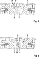
- FIGS. 3 to 9 each show a section FIG. 2 , with each other embodiment of the compressed air passage 24. These different configurations of the compressed air passage 24 can all be combined. Thus, it is possible that 15 different compressed air passages 24 are formed in the region of a support surface.
- FIG. 3 is located in the bearing surface facing side of the screw head, a groove 27 which forms the compressed air passage 24.
- a short channel 28 is provided in the wheel bearing 3. This channel 28 leads, bypassing the support surface 15 from the Radlagerringraum 20 in the third annular space 21st
- a short channel 28 leads straight through the head of the screw.
- FIG. 6 shows a further formation of the channel 28 in the screw 14.
- a first radially directed channel 28 leads from Radlagerringraum 20 to the longitudinal axis of the screw 14.
- a second channel 28 leads to the middle of the screw head and thus in the third annular space 21.
- the screw head has, for example, a hexagon socket.
- the channel 28 in FIG. 6 flows into this hexagon socket.
- channels are formed as short as possible and bypass only the support surface 15.
- the channels can be in the simplest Form to be performed as holes. Alternatively, appropriate tubes can be inserted in castings.
- a washer 29 is used at the bearing surface 15.
- a groove 27 is provided which forms the compressed air passage 24.
- FIG. 8 can also be formed as a compressed air passage 24 in the washer 29, a channel 28.
- FIG. 9 shows the use of a spring ring 30 on the support surface 15.
- the corresponding waveform of the spring ring 30 provides sufficient space, which is available as a compressed air passage 24.
- the compressed air passage 24 in the form of grooves 27 or channels 28 is also provided to use an air-permeable material in the corresponding region of the wheel bearing 3, the screw 14, the washer 29 or the spring ring 30.
- the air-permeable material is in particular porous material, for example sintered metal, metal foam or porous PTFE foam.
- the compressed air supply from the vehicle-side compressed air source to a first annular space (19), from the first annular space (19) by the free spaces (26) between the teeth of the toothing (13) of the toothing (13) in a second annulus (20) from the second annulus (20) to the wheel (7) leads.
- a compressed air line (18) in and / or on the wheel carrier (2) from the compressed air source to the first annulus (19) lead.
- the first annulus (19) can be formed by at least one non-rotating part of the arrangement (1), in particular the wheel carrier (2), and at least one rotating part of the arrangement (1), in particular output shaft (11) and / or wheel bearing (3 ), wherein the first annular space (19) is sealed from the environment by means of a sealing arrangement (22).
- the sealing arrangement (22) of such an arrangement can comprise at least one sealing lip (51), wherein the sealing lip (51) does not seal and does not grind at a correspondingly low pressure in the first annular space (19), and the sealing lip (51) is pressed by a correspondingly high pressure. is movable and thus seals.
- the wheel bearing (3) by means of a screw (14) with the output shaft (11) to be clamped, wherein the screw (14) coaxial with the output shaft (11) is arranged, and wherein the second annular space (20) Inside the wheel bearing (3) and radially outside the screw (14) is defined. Provision may be made for a bearing surface (15) on the wheel bearing (3) on which the screw (14) rests, and at least one compressed air passage (24) in the region of the bearing surface (15), wherein the compressed air passage (24) from the second annular space (20 ) leads into a third annular space (21).
- the arrangement comprises a control valve (17) in the compressed air guide between the pressure source and the tire (9), wherein the control valve (17) between the third annulus (21) and the tire (9), preferably in the hub region of the wheel (7) or in Wheel bearing (3) is arranged.
- FIG. 13 shows a schematic view of such an arrangement 100 for tire inflation pressure control of a vehicle.
- the assembly 100 is used to perform a method of tire inflation pressure control of the vehicle.
- the structural design of the arrangement 100 corresponds to the illustrations in FIGS FIGS. 1 to 12 ,
- FIG. 13 shows the assembly 100, which is basically divided into a non-rotating portion 200 and a rotating portion 300.
- the non-rotating portion 200 is disposed in the vehicle, for example, within the body.
- the tire 9 is shown in detail. Further, this rotating portion 300 includes the wheel 7 on which the tire 9 is mounted, and the wheel bearing 3 on which the wheel 7 is mounted.
- the non-rotating portion 200 is a compressed air source 400 and a control unit 500.
- the compressed air guide leads from the non-rotating portion 200 in the rotating portion 300, in particular to the tire 9.
- the rotary feedthrough 600 would be exemplified by the Gearing 13 described.
- the compressed air source 400 includes a motor 700. This may be a separate electric motor. Alternatively, the drive unit of the vehicle can also be used here. Via the motor 700, a compressor 800 is driven. The compressor 800 compresses air and introduces it into a pressure accumulator 1000. Between the compressor 800 and the pressure accumulator 1000 is an air treatment 900 for air drying.
- the control unit 500 comprises two parallel-connected solenoid valves 1200, 1300.
- the first solenoid valve 1200 is preceded by a pressure reducer 1100.
- the solenoid valves 1200, 1300 are here designed as shut-off valves, which can be either open or closed. Due to the pressure reducer 1100, the first solenoid valve 1200 may release a first, lower pressure. At the second solenoid valve 1300 is a second higher pressure.
- the compressed air guide leads to the solenoid valves 1200, 1300 to a manifold block 1400. About this manifold block 1400 leads the compressed air supply to the individual tires 9 of the vehicle. For the sake of simplicity, only one tire 9 is shown here.
- the control unit 500 includes a signal processor 1500 and a radio receiver 1600.
- the signal processor 1500 drives the two solenoid valves 1200, 1300.
- the signal processor 1500 also drives the distribution block 1400 as well as the motor 700. It is crucial that the signal processing 1500 by the actuation of the two solenoid valves 1200, 1300 can forward at least two different pressures on the compressed air guide in the rotating portion 300.
- control valve 17 In the rotating portion 300 in the compressed air guide is the control valve 17.
- This control valve 17 allows at least two switching positions. In the first switching position, the tire 9 can be filled. In the second switching position compressed air can be discharged from the tire 9.
- a pressure sensor 1700 and a temperature sensor 1800 are provided in the rotating portion.
- the pressure sensor 1700 measures the actual pressure in the tire 9.
- the temperature sensor 1800 measures the temperature in or on the tire 9.
- a radio transmitter 2100 of the rotating portion 300 wirelessly transmits the actual pressure and the measured temperatures to the radio receiver 1600 of the control unit 500.
- the wireless transmission is via electromagnetic waves, light or sound.
- the control valve 17 comprises a linearly movable valve body 3000, preferably designed as a piston.
- This valve body 3000 is loaded by a spring 3100. By linear displacement of the valve body 3000, the two switching positions for filling the tire 9 and for discharging the compressed air can be achieved.
- the valve body 3000 is movable by the pressure in the compressed air guide against the spring force.
- FIG. 10 shows in detail with the section BB a rim line 25 which leads within the wheel 7 from the hub area through the spoke to the rim and thus into the tire 9. About this rim line 25 compressed air can be introduced into the tire 9 and drained from the tire 9.
- FIG. 13 shows the possibility to control the control valve 19 only via the pneumatic pressure.
- it requires no additional lines from the non-rotating portion 200 in the rotating portion 300.
- the pressure sensor 1700 To adjust the actual pressure in the tire 9 to the desired target pressure, it requires the pressure sensor 1700 and a corresponding return of the measured data.
- the wireless data transmission is used.
- no additional cable between the rotating portion 300 and the non-rotating portion 200 is required for this transmission.
- the pressure sensor 1700 and the temperature sensor 1800 in the rotating portion the corresponding values can be measured very close to the tire 9 or the tire 9.
Landscapes
- Engineering & Computer Science (AREA)
- Mechanical Engineering (AREA)
- Rolling Contact Bearings (AREA)
- Tires In General (AREA)
Claims (10)
- Dispositif (1) permettant l'alimentation en air comprimé d'une roue (7) d'un véhicule comprenant :- une roue (7) équipée de pneus (9),- un arbre de sortie (11) permettant de transmettre le couple de rotation à la roue (7),- un palier de roue (3) sur lequel la roue (7) est montée solidairement en rotation,- une denture (13) située entre l'arbre de sortie (11) et le palier de roue (3),le palier de roue (3) étant serré avec l'arbre de sortie (11) au moyen d'une vis (14), la vis (14) étant montée coaxialement à l'arbre de sortie (11) et une chambre annulaire de palier de roue (20) étant définie à la partie interne du palier de roue et radialement à l'extérieur de la vis (14),
au moins un passage d'air comprimé (24) de la chambre annulaire du palier de roue (20) en direction de la roue (7), et
un guidage d'air comprimé qui conduit d'une source d'air comprimé située côté véhicule dans la chambre annulaire du palier de roue (20), de la chambre annulaire du palier de roue (20) au travers du passage d'air comprimé (24) vers la roue (7) et de la roue (7) dans les pneus (9). - Dispositif conforme à la revendication 1,
caractérisé en ce que
la tête de la vis (14) s'applique sur une surface d'appui (15) sur le palier de roue (3), et le passage d'air comprimé (24) est formé dans la zone de la surface d'appui (15) et/ou dans le palier de roue (3) et/ou dans la vis (14). - Dispositif conforme à l'une des revendications précédentes,
caractérisé en ce que
le passage d'air comprimé (24) est formé par une rainure (27) située dans le palier de roue (3) sur la surface d'appui (15) et/ou par une rainure (27) située dans la tête de la vis sur la surface d'appui (15) et/ou par un canal (28) situé dans le palier de roue (3) et/ou par un canal (28) situé dans la vis (14). - Dispositif conforme à l'une des revendications précédentes,
caractérisé par
une rondelle d'insertion (29) située sur la surface d'appui (15), le passage d'air comprimé (24) étant formé par une rainure (27) ou par un canal (28) ou par un évidement situé dans la rondelle d'insertion (29) et/ou par une bague élastique (30) située sur la surface d'appui (15), le passage d'air comprimé (24) étant formé par la forme ondulée de la bague élastique (30). - Dispositif conforme à l'une des revendications précédentes,
caractérisé en ce qu'
une partie du palier de roue (3) et/ou au moins une partie de la vis (14) et/ou au moins une partie d'une rondelle située sur la surface d'appui (15) est réalisée en un matériau perméable à l'air, de préférence un métal fritté, une mousse métallique, une mousse de PTFE poreuse, le matériau perméable à l'air formant le passage d'air comprimé (24). - Dispositif conforme à l'une des revendications précédentes,
caractérisé en ce que
le guidage d'air comprimé conduit de la source d'air comprimé, en passant par les espaces libres (26) situés entre les dents de la denture (13) dans la chambre annulaire du palier de roue (20). - Dispositif conforme à la revendication 6,
caractérisé en ce que
le guidage d'air comprimé conduit de la source d'air comprimé située côté véhicule à une première chambre annulaire (19), de la première chambre annulaire (19), au travers des intervalles libres (26) situés entre les dents de la denture (13), de la denture (13) dans la chambre annulaire (20) du palier de roue, de la chambre annulaire du palier de roue (20) vers la roue (7). - Dispositif conforme à la revendication 7,
caractérisé par
un support de roue (2) pouvant être fixé sur le véhicule, le palier de roue (3) étant monté rotatif sur le support de roue (2) et par une conduite d'air comprimé (18) située dans et/ou sur le support de roue (2) qui conduit de la source d'air comprimé vers la première chambre annulaire (19). - Dispositif conforme à l'une des revendications 7 et 8,
caractérisé en ce que
la première chambre annulaire (19) est formée par au moins une partie non rotative du dispositif (1), en particulier le support de roue (2) et par au moins une partie rotative du dispositif (1), en particulier l'arbre de sortie (11) et/ou le palier de roue (3), la première chambre annulaire (19) étant rendue étanche vis-à-vis de l'environnement au moyen d'un dispositif d'étanchéité (22). - Dispositif conforme à la revendication 9,
caractérisé en ce que
le dispositif d'étanchéité (22) comporte au moins une lèvre d'étanchéité (51), en présence d'une pression faible correspondante dans la première chambre annulaire (19), la lèvre d'étanchéité (51) n'assurant pas l'étanchéité, et n'effectuant pas de meulage, et, en présence d'une haute pression correspondante, la lèvre d'étanchéité (51) étant mobile et assurant ainsi l'étanchéité.
Priority Applications (1)
| Application Number | Priority Date | Filing Date | Title |
|---|---|---|---|
| EP18184265.9A EP3415346B1 (fr) | 2014-10-01 | 2015-09-01 | Dispositif d'alimentation en air comprimé d'une roue d'un véhicule |
Applications Claiming Priority (4)
| Application Number | Priority Date | Filing Date | Title |
|---|---|---|---|
| DE102014219983.2A DE102014219983A1 (de) | 2014-10-01 | 2014-10-01 | Verfahren und Anordnung zur Reifenfülldruckregelung eines Fahrzeuges |
| DE102014219981.6A DE102014219981A1 (de) | 2014-10-01 | 2014-10-01 | Anordnung zur Druckluftversorgung eines Rades eines Fahrzeuges |
| DE102014219980.8A DE102014219980B4 (de) | 2014-10-01 | 2014-10-01 | Anordnung zur Druckluftversorgung eines Rades eines Fahrzeuges |
| PCT/EP2015/069944 WO2016050431A1 (fr) | 2014-10-01 | 2015-09-01 | Système et procédé d'alimentation en air comprimé d'une roue d'un véhicule |
Related Child Applications (2)
| Application Number | Title | Priority Date | Filing Date |
|---|---|---|---|
| EP18184265.9A Division-Into EP3415346B1 (fr) | 2014-10-01 | 2015-09-01 | Dispositif d'alimentation en air comprimé d'une roue d'un véhicule |
| EP18184265.9A Division EP3415346B1 (fr) | 2014-10-01 | 2015-09-01 | Dispositif d'alimentation en air comprimé d'une roue d'un véhicule |
Publications (2)
| Publication Number | Publication Date |
|---|---|
| EP3201013A1 EP3201013A1 (fr) | 2017-08-09 |
| EP3201013B1 true EP3201013B1 (fr) | 2018-08-29 |
Family
ID=54012223
Family Applications (2)
| Application Number | Title | Priority Date | Filing Date |
|---|---|---|---|
| EP18184265.9A Active EP3415346B1 (fr) | 2014-10-01 | 2015-09-01 | Dispositif d'alimentation en air comprimé d'une roue d'un véhicule |
| EP15756661.3A Active EP3201013B1 (fr) | 2014-10-01 | 2015-09-01 | Système et procédé d'alimentation en air comprimé d'une roue d'un véhicule |
Family Applications Before (1)
| Application Number | Title | Priority Date | Filing Date |
|---|---|---|---|
| EP18184265.9A Active EP3415346B1 (fr) | 2014-10-01 | 2015-09-01 | Dispositif d'alimentation en air comprimé d'une roue d'un véhicule |
Country Status (4)
| Country | Link |
|---|---|
| US (1) | US10434825B2 (fr) |
| EP (2) | EP3415346B1 (fr) |
| CN (1) | CN106715162B (fr) |
| WO (1) | WO2016050431A1 (fr) |
Families Citing this family (4)
| Publication number | Priority date | Publication date | Assignee | Title |
|---|---|---|---|---|
| DE102016205007A1 (de) | 2016-03-24 | 2017-09-28 | Bayerische Motoren Werke Aktiengesellschaft | Druckluftversorgungseinrichtung für einen Fahrzeugreifen |
| DE102017208213A1 (de) | 2017-05-16 | 2018-11-22 | Bayerische Motoren Werke Aktiengesellschaft | Reifendruckregelsystem eines Fahrzeugs |
| DE102018130307A1 (de) | 2018-01-26 | 2019-08-01 | Illinois Tool Works Inc. | Drehübertragungsvorrichtung zum Übertragen von Steuer- und/oder Arbeitsdrücken zu einer Radnabe oder einer von der Radnabe aufgenommenen Fahrzeugfelge |
| CN113320339B (zh) * | 2020-02-29 | 2022-05-27 | 关磊 | 一种新能源车辆减速转向及减震防撞系统 |
Family Cites Families (33)
| Publication number | Priority date | Publication date | Assignee | Title |
|---|---|---|---|---|
| DE1938202A1 (de) * | 1969-07-28 | 1971-02-11 | Graubremse Gmbh | An eine fahrzeugeigene Reifenfuelleinrichtung anzuschliessendes luftbereiftes Fahrzeugrad |
| JPS561245B2 (fr) * | 1974-03-30 | 1981-01-12 | ||
| DE3116720C1 (de) * | 1981-04-28 | 1982-10-28 | Loehr & Bromkamp Gmbh | Lagerungsanordnung einer ueber ein Gleichlaufdrehgelenk antreibbaren Radnabe |
| DE3405111C2 (de) | 1984-02-14 | 1994-02-10 | Wabco Vermoegensverwaltung | Einrichtung zur Änderung des Druckes in den Reifen eines Fahrzeuges |
| US4932451A (en) * | 1989-01-26 | 1990-06-12 | General Motors Corporation | Vehicle wheel end assembly with air passage |
| US5080156A (en) * | 1990-02-12 | 1992-01-14 | Bartos Josef A | Vehicle wheel and axle assembly for controlling air pressure in tires with spaces between the bearing elements and the race members included in the air flow path |
| FR2667826B1 (fr) | 1990-10-12 | 1993-01-22 | Fazekas Stephane | Dispositif de transfert de fluide sous pression relative dans une installation de regulation de la pression de gonflage d'un pneumatique de vehicule roulant. |
| FR2675744B1 (fr) | 1991-04-23 | 1995-05-19 | Stephane Fazekas | Dispositif pneumatique pilote de gonflage-degonflage automatique d'une capacite de confinement d'un fluide gazeux sous pression relative. |
| FR2731655B1 (fr) * | 1995-03-16 | 1997-07-25 | Giat Ind Sa | Installation de commande a distance du gonflage-degonflage du pneumatique d'une roue de vehicule |
| DE19961020A1 (de) | 1999-12-17 | 2000-06-21 | Post Dieter | Automatische Reifenluftdruckregulierung mit intregierter Reifenpannenbehebung für alle Kraftfahrzeuge |
| ATE451259T1 (de) * | 2001-04-09 | 2009-12-15 | Michelin Soc Tech | Luftaufblasanordnung, insbesondere für einen auf einem rad montierten reifen, und entsprechendes rad |
| FR2837747B1 (fr) * | 2002-03-29 | 2004-07-09 | Syegon | Dispositif auto-obturant du pneumatique d'une roue de vehicule |
| DE10360764B3 (de) | 2003-12-23 | 2005-10-06 | Ludwig Prof. Dr. Volk | Vorrichtung zum Einstellen des Reifendrucks an einem Fahrzeug mit bereiften Rädern |
| FR2872087B1 (fr) | 2004-06-28 | 2008-02-15 | Michelin Soc Tech | Ensemble monte d'une roue et d'un pneumatique, comprenant des moyens de surveillance de la pression regnant a l'interieur du pneumatique, systeme comprenant un tel ensemble |
| JP2006248258A (ja) | 2005-03-08 | 2006-09-21 | Nsk Ltd | 空気圧制御機構付車輪支持用軸受 |
| JP4529899B2 (ja) * | 2005-12-28 | 2010-08-25 | トヨタ自動車株式会社 | 空気供給装置 |
| FR2896725B1 (fr) * | 2006-01-30 | 2008-05-02 | Michel Maquaire | Vanne de roue pour vehicule permettant le controle de sa pression de gonflage |
| JP4997864B2 (ja) | 2006-06-28 | 2012-08-08 | 日本精工株式会社 | エアコンプレッサ付車輪支持用転がり軸受ユニット |
| JP2008239025A (ja) * | 2007-03-28 | 2008-10-09 | Jtekt Corp | 車輪用転がり軸受装置 |
| US8210752B2 (en) * | 2007-09-26 | 2012-07-03 | Jtekt Corporation | Wheel supporting device |
| US20090084481A1 (en) * | 2007-10-01 | 2009-04-02 | Kalavitz Michael V | Tire inflation control method and apparatus |
| EP2441594B1 (fr) | 2007-10-03 | 2013-04-24 | JTEKT Corporation | Appareil de support de roue |
| DE102008062073B4 (de) | 2008-12-12 | 2020-01-02 | Knorr-Bremse Systeme für Nutzfahrzeuge GmbH | Reifendruckregelsystem und Verfahren zur Reifendruckregelung |
| DE102009048750A1 (de) | 2009-10-08 | 2011-04-14 | Claas Industrietechnik Gmbh | Reifendruck-Regelanlage und Ventilbaugruppe dafür |
| DE102009051930A1 (de) | 2009-11-04 | 2010-07-15 | Schaeffler Technologies Gmbh & Co. Kg | Radlagereinheit mit axialer Verzahnung |
| CN101863199B (zh) | 2010-07-09 | 2013-01-02 | 中国北方车辆研究所 | 一种汽车中央充放气系统气路 |
| CN103328234A (zh) * | 2010-11-24 | 2013-09-25 | 弗利特科技有限责任公司 | 用于车载自动轮胎充气系统的轴到轴密封气路 |
| DE102011006123B4 (de) * | 2011-03-25 | 2022-01-20 | Bayerische Motoren Werke Aktiengesellschaft | Radträger mit Radlager für ein Kraftfahrzeug |
| JP5870556B2 (ja) * | 2011-08-31 | 2016-03-01 | 株式会社ジェイテクト | サイドフェーススプラインの形状測定方法 |
| JP6070686B2 (ja) * | 2012-02-21 | 2017-02-01 | 横浜ゴム株式会社 | 車両用ハブユニットおよび空気圧調整装置 |
| WO2013125395A1 (fr) * | 2012-02-21 | 2013-08-29 | 横浜ゴム株式会社 | Roue et dispositif de réglage de pression d'air |
| DE102013207855B4 (de) | 2013-04-30 | 2021-02-11 | Schaeffler Technologies AG & Co. KG | Lager mit Drehdurchführung sowie Reifendruckregelanlage mit einem derartigen Lager |
| DE102014108028B3 (de) * | 2014-06-06 | 2015-09-24 | Kessler & Co. Gmbh & Co. Kg | Drehdurchführung für ein Kraftfahrzeugrad |
-
2015
- 2015-09-01 WO PCT/EP2015/069944 patent/WO2016050431A1/fr not_active Ceased
- 2015-09-01 EP EP18184265.9A patent/EP3415346B1/fr active Active
- 2015-09-01 EP EP15756661.3A patent/EP3201013B1/fr active Active
- 2015-09-01 CN CN201580049318.1A patent/CN106715162B/zh active Active
-
2017
- 2017-03-31 US US15/476,358 patent/US10434825B2/en active Active
Also Published As
| Publication number | Publication date |
|---|---|
| WO2016050431A1 (fr) | 2016-04-07 |
| EP3415346A1 (fr) | 2018-12-19 |
| CN106715162B (zh) | 2019-04-09 |
| CN106715162A (zh) | 2017-05-24 |
| EP3415346B1 (fr) | 2023-06-07 |
| US20170203618A1 (en) | 2017-07-20 |
| US10434825B2 (en) | 2019-10-08 |
| EP3201013A1 (fr) | 2017-08-09 |
Similar Documents
| Publication | Publication Date | Title |
|---|---|---|
| EP2613950B1 (fr) | Système de régulation de la pression des pneus présentant un passage tournant | |
| DE102009007691B3 (de) | Niveauregelventil mit druckbelasteter Ventilscheibe | |
| EP2114701A1 (fr) | Essieu et arbre d'entraînement ou de transmission pour véhicules à système central d'alimentation en pression de gonflage | |
| EP3370983B1 (fr) | Ensemble de soupape de roue et système de régulation de pression de pneumatique comprenant au moins un tel ensemble de soupape de roue | |
| WO2010092038A2 (fr) | Dispositif destiné à régler la pression du gaz dans un pneumatique du véhicule automobile | |
| EP3415346B1 (fr) | Dispositif d'alimentation en air comprimé d'une roue d'un véhicule | |
| WO2015144353A1 (fr) | Roue comportant un pneu rempli de fluide et un dispositif de réglage de la pression de pneu ainsi qu'une bicyclette, une automobile ou un aéronef équipé de telles roues | |
| DE112014005076T5 (de) | Automatisches Reifenfüllsystem mit doppelter Pumpe für eine Lkw-Anordnung | |
| EP1874563B1 (fr) | Dispositif, en particulier passage tournant | |
| WO2021160211A1 (fr) | Vis à rouleaux satellites | |
| EP3341226B1 (fr) | Agencement de valves de roue et système de régulation de la pression des pneus comportant un tel agencement de valves de roue | |
| DE69107001T2 (de) | Übertragungseinrichtung für ein Fluid unter relativem Druck mit Hilfe einer Druckregeleinrichtung eines während der Fahrt aufblasbaren Reifens. | |
| DE102014219983A1 (de) | Verfahren und Anordnung zur Reifenfülldruckregelung eines Fahrzeuges | |
| DE102009007674A1 (de) | Niveauregelventil mit je einem Anschluss für Luftfederbälge der rechten und der linken Seite | |
| DE102014219981A1 (de) | Anordnung zur Druckluftversorgung eines Rades eines Fahrzeuges | |
| DE102015213692A1 (de) | Radnabenantrieb | |
| EP2558307B1 (fr) | Ensemble de roulement d'une roue motrice de véhicule | |
| DE102005006073A1 (de) | Vorrichtung, insbesondere Drehdurchführung | |
| EP2837512B1 (fr) | Suspension | |
| DE102014221813B3 (de) | Einrichtung zur Einstellung des Luftdrucks eines an einer Fahrzeugachse über eine Felge angeordneten Luftreifens | |
| EP2306040B1 (fr) | Frein à disque et tige d'un frein à disque | |
| DE102012008184A1 (de) | Rotierbare Spannvorrichtung | |
| DE102014219980B4 (de) | Anordnung zur Druckluftversorgung eines Rades eines Fahrzeuges | |
| EP2818336B1 (fr) | Dispositif de régulation de la pression d'un fluide dans un pneu de véhicule | |
| DE102019116352A1 (de) | Fahrlagenverstellung und Beladungsausgleich |
Legal Events
| Date | Code | Title | Description |
|---|---|---|---|
| STAA | Information on the status of an ep patent application or granted ep patent |
Free format text: STATUS: THE INTERNATIONAL PUBLICATION HAS BEEN MADE |
|
| PUAI | Public reference made under article 153(3) epc to a published international application that has entered the european phase |
Free format text: ORIGINAL CODE: 0009012 |
|
| STAA | Information on the status of an ep patent application or granted ep patent |
Free format text: STATUS: REQUEST FOR EXAMINATION WAS MADE |
|
| 17P | Request for examination filed |
Effective date: 20170426 |
|
| AK | Designated contracting states |
Kind code of ref document: A1 Designated state(s): AL AT BE BG CH CY CZ DE DK EE ES FI FR GB GR HR HU IE IS IT LI LT LU LV MC MK MT NL NO PL PT RO RS SE SI SK SM TR |
|
| AX | Request for extension of the european patent |
Extension state: BA ME |
|
| DAV | Request for validation of the european patent (deleted) | ||
| DAX | Request for extension of the european patent (deleted) | ||
| GRAP | Despatch of communication of intention to grant a patent |
Free format text: ORIGINAL CODE: EPIDOSNIGR1 |
|
| STAA | Information on the status of an ep patent application or granted ep patent |
Free format text: STATUS: GRANT OF PATENT IS INTENDED |
|
| INTG | Intention to grant announced |
Effective date: 20180316 |
|
| GRAS | Grant fee paid |
Free format text: ORIGINAL CODE: EPIDOSNIGR3 |
|
| GRAA | (expected) grant |
Free format text: ORIGINAL CODE: 0009210 |
|
| STAA | Information on the status of an ep patent application or granted ep patent |
Free format text: STATUS: THE PATENT HAS BEEN GRANTED |
|
| AK | Designated contracting states |
Kind code of ref document: B1 Designated state(s): AL AT BE BG CH CY CZ DE DK EE ES FI FR GB GR HR HU IE IS IT LI LT LU LV MC MK MT NL NO PL PT RO RS SE SI SK SM TR |
|
| REG | Reference to a national code |
Ref country code: GB Ref legal event code: FG4D Free format text: NOT ENGLISH |
|
| REG | Reference to a national code |
Ref country code: CH Ref legal event code: EP |
|
| REG | Reference to a national code |
Ref country code: AT Ref legal event code: REF Ref document number: 1034686 Country of ref document: AT Kind code of ref document: T Effective date: 20180915 |
|
| REG | Reference to a national code |
Ref country code: IE Ref legal event code: FG4D Free format text: LANGUAGE OF EP DOCUMENT: GERMAN |
|
| REG | Reference to a national code |
Ref country code: DE Ref legal event code: R096 Ref document number: 502015005720 Country of ref document: DE |
|
| REG | Reference to a national code |
Ref country code: FR Ref legal event code: PLFP Year of fee payment: 4 |
|
| REG | Reference to a national code |
Ref country code: NL Ref legal event code: MP Effective date: 20180829 |
|
| REG | Reference to a national code |
Ref country code: LT Ref legal event code: MG4D |
|
| PG25 | Lapsed in a contracting state [announced via postgrant information from national office to epo] |
Ref country code: NO Free format text: LAPSE BECAUSE OF FAILURE TO SUBMIT A TRANSLATION OF THE DESCRIPTION OR TO PAY THE FEE WITHIN THE PRESCRIBED TIME-LIMIT Effective date: 20181129 Ref country code: SE Free format text: LAPSE BECAUSE OF FAILURE TO SUBMIT A TRANSLATION OF THE DESCRIPTION OR TO PAY THE FEE WITHIN THE PRESCRIBED TIME-LIMIT Effective date: 20180829 Ref country code: NL Free format text: LAPSE BECAUSE OF FAILURE TO SUBMIT A TRANSLATION OF THE DESCRIPTION OR TO PAY THE FEE WITHIN THE PRESCRIBED TIME-LIMIT Effective date: 20180829 Ref country code: BG Free format text: LAPSE BECAUSE OF FAILURE TO SUBMIT A TRANSLATION OF THE DESCRIPTION OR TO PAY THE FEE WITHIN THE PRESCRIBED TIME-LIMIT Effective date: 20181129 Ref country code: RS Free format text: LAPSE BECAUSE OF FAILURE TO SUBMIT A TRANSLATION OF THE DESCRIPTION OR TO PAY THE FEE WITHIN THE PRESCRIBED TIME-LIMIT Effective date: 20180829 Ref country code: IS Free format text: LAPSE BECAUSE OF FAILURE TO SUBMIT A TRANSLATION OF THE DESCRIPTION OR TO PAY THE FEE WITHIN THE PRESCRIBED TIME-LIMIT Effective date: 20181229 Ref country code: GR Free format text: LAPSE BECAUSE OF FAILURE TO SUBMIT A TRANSLATION OF THE DESCRIPTION OR TO PAY THE FEE WITHIN THE PRESCRIBED TIME-LIMIT Effective date: 20181130 Ref country code: FI Free format text: LAPSE BECAUSE OF FAILURE TO SUBMIT A TRANSLATION OF THE DESCRIPTION OR TO PAY THE FEE WITHIN THE PRESCRIBED TIME-LIMIT Effective date: 20180829 Ref country code: LT Free format text: LAPSE BECAUSE OF FAILURE TO SUBMIT A TRANSLATION OF THE DESCRIPTION OR TO PAY THE FEE WITHIN THE PRESCRIBED TIME-LIMIT Effective date: 20180829 |
|
| PG25 | Lapsed in a contracting state [announced via postgrant information from national office to epo] |
Ref country code: AL Free format text: LAPSE BECAUSE OF FAILURE TO SUBMIT A TRANSLATION OF THE DESCRIPTION OR TO PAY THE FEE WITHIN THE PRESCRIBED TIME-LIMIT Effective date: 20180829 Ref country code: LV Free format text: LAPSE BECAUSE OF FAILURE TO SUBMIT A TRANSLATION OF THE DESCRIPTION OR TO PAY THE FEE WITHIN THE PRESCRIBED TIME-LIMIT Effective date: 20180829 Ref country code: HR Free format text: LAPSE BECAUSE OF FAILURE TO SUBMIT A TRANSLATION OF THE DESCRIPTION OR TO PAY THE FEE WITHIN THE PRESCRIBED TIME-LIMIT Effective date: 20180829 |
|
| PG25 | Lapsed in a contracting state [announced via postgrant information from national office to epo] |
Ref country code: PL Free format text: LAPSE BECAUSE OF FAILURE TO SUBMIT A TRANSLATION OF THE DESCRIPTION OR TO PAY THE FEE WITHIN THE PRESCRIBED TIME-LIMIT Effective date: 20180829 Ref country code: ES Free format text: LAPSE BECAUSE OF FAILURE TO SUBMIT A TRANSLATION OF THE DESCRIPTION OR TO PAY THE FEE WITHIN THE PRESCRIBED TIME-LIMIT Effective date: 20180829 Ref country code: CZ Free format text: LAPSE BECAUSE OF FAILURE TO SUBMIT A TRANSLATION OF THE DESCRIPTION OR TO PAY THE FEE WITHIN THE PRESCRIBED TIME-LIMIT Effective date: 20180829 Ref country code: IT Free format text: LAPSE BECAUSE OF FAILURE TO SUBMIT A TRANSLATION OF THE DESCRIPTION OR TO PAY THE FEE WITHIN THE PRESCRIBED TIME-LIMIT Effective date: 20180829 Ref country code: RO Free format text: LAPSE BECAUSE OF FAILURE TO SUBMIT A TRANSLATION OF THE DESCRIPTION OR TO PAY THE FEE WITHIN THE PRESCRIBED TIME-LIMIT Effective date: 20180829 Ref country code: EE Free format text: LAPSE BECAUSE OF FAILURE TO SUBMIT A TRANSLATION OF THE DESCRIPTION OR TO PAY THE FEE WITHIN THE PRESCRIBED TIME-LIMIT Effective date: 20180829 |
|
| REG | Reference to a national code |
Ref country code: CH Ref legal event code: PL |
|
| PG25 | Lapsed in a contracting state [announced via postgrant information from national office to epo] |
Ref country code: SK Free format text: LAPSE BECAUSE OF FAILURE TO SUBMIT A TRANSLATION OF THE DESCRIPTION OR TO PAY THE FEE WITHIN THE PRESCRIBED TIME-LIMIT Effective date: 20180829 Ref country code: SM Free format text: LAPSE BECAUSE OF FAILURE TO SUBMIT A TRANSLATION OF THE DESCRIPTION OR TO PAY THE FEE WITHIN THE PRESCRIBED TIME-LIMIT Effective date: 20180829 Ref country code: DK Free format text: LAPSE BECAUSE OF FAILURE TO SUBMIT A TRANSLATION OF THE DESCRIPTION OR TO PAY THE FEE WITHIN THE PRESCRIBED TIME-LIMIT Effective date: 20180829 |
|
| REG | Reference to a national code |
Ref country code: DE Ref legal event code: R097 Ref document number: 502015005720 Country of ref document: DE |
|
| REG | Reference to a national code |
Ref country code: BE Ref legal event code: MM Effective date: 20180930 |
|
| REG | Reference to a national code |
Ref country code: IE Ref legal event code: MM4A |
|
| PG25 | Lapsed in a contracting state [announced via postgrant information from national office to epo] |
Ref country code: LU Free format text: LAPSE BECAUSE OF NON-PAYMENT OF DUE FEES Effective date: 20180901 Ref country code: MC Free format text: LAPSE BECAUSE OF FAILURE TO SUBMIT A TRANSLATION OF THE DESCRIPTION OR TO PAY THE FEE WITHIN THE PRESCRIBED TIME-LIMIT Effective date: 20180829 |
|
| PLBE | No opposition filed within time limit |
Free format text: ORIGINAL CODE: 0009261 |
|
| STAA | Information on the status of an ep patent application or granted ep patent |
Free format text: STATUS: NO OPPOSITION FILED WITHIN TIME LIMIT |
|
| PG25 | Lapsed in a contracting state [announced via postgrant information from national office to epo] |
Ref country code: IE Free format text: LAPSE BECAUSE OF NON-PAYMENT OF DUE FEES Effective date: 20180901 |
|
| 26N | No opposition filed |
Effective date: 20190531 |
|
| PG25 | Lapsed in a contracting state [announced via postgrant information from national office to epo] |
Ref country code: LI Free format text: LAPSE BECAUSE OF NON-PAYMENT OF DUE FEES Effective date: 20180930 Ref country code: BE Free format text: LAPSE BECAUSE OF NON-PAYMENT OF DUE FEES Effective date: 20180930 Ref country code: SI Free format text: LAPSE BECAUSE OF FAILURE TO SUBMIT A TRANSLATION OF THE DESCRIPTION OR TO PAY THE FEE WITHIN THE PRESCRIBED TIME-LIMIT Effective date: 20180829 Ref country code: CH Free format text: LAPSE BECAUSE OF NON-PAYMENT OF DUE FEES Effective date: 20180930 |
|
| PG25 | Lapsed in a contracting state [announced via postgrant information from national office to epo] |
Ref country code: MT Free format text: LAPSE BECAUSE OF FAILURE TO SUBMIT A TRANSLATION OF THE DESCRIPTION OR TO PAY THE FEE WITHIN THE PRESCRIBED TIME-LIMIT Effective date: 20180829 |
|
| PG25 | Lapsed in a contracting state [announced via postgrant information from national office to epo] |
Ref country code: TR Free format text: LAPSE BECAUSE OF FAILURE TO SUBMIT A TRANSLATION OF THE DESCRIPTION OR TO PAY THE FEE WITHIN THE PRESCRIBED TIME-LIMIT Effective date: 20180829 |
|
| PG25 | Lapsed in a contracting state [announced via postgrant information from national office to epo] |
Ref country code: PT Free format text: LAPSE BECAUSE OF FAILURE TO SUBMIT A TRANSLATION OF THE DESCRIPTION OR TO PAY THE FEE WITHIN THE PRESCRIBED TIME-LIMIT Effective date: 20180829 |
|
| PG25 | Lapsed in a contracting state [announced via postgrant information from national office to epo] |
Ref country code: CY Free format text: LAPSE BECAUSE OF FAILURE TO SUBMIT A TRANSLATION OF THE DESCRIPTION OR TO PAY THE FEE WITHIN THE PRESCRIBED TIME-LIMIT Effective date: 20180829 Ref country code: MK Free format text: LAPSE BECAUSE OF NON-PAYMENT OF DUE FEES Effective date: 20180829 Ref country code: HU Free format text: LAPSE BECAUSE OF FAILURE TO SUBMIT A TRANSLATION OF THE DESCRIPTION OR TO PAY THE FEE WITHIN THE PRESCRIBED TIME-LIMIT; INVALID AB INITIO Effective date: 20150901 |
|
| REG | Reference to a national code |
Ref country code: AT Ref legal event code: MM01 Ref document number: 1034686 Country of ref document: AT Kind code of ref document: T Effective date: 20200901 |
|
| PG25 | Lapsed in a contracting state [announced via postgrant information from national office to epo] |
Ref country code: AT Free format text: LAPSE BECAUSE OF NON-PAYMENT OF DUE FEES Effective date: 20200901 |
|
| P01 | Opt-out of the competence of the unified patent court (upc) registered |
Effective date: 20230427 |
|
| PGFP | Annual fee paid to national office [announced via postgrant information from national office to epo] |
Ref country code: DE Payment date: 20250909 Year of fee payment: 11 |
|
| PGFP | Annual fee paid to national office [announced via postgrant information from national office to epo] |
Ref country code: GB Payment date: 20250923 Year of fee payment: 11 |
|
| PGFP | Annual fee paid to national office [announced via postgrant information from national office to epo] |
Ref country code: FR Payment date: 20250926 Year of fee payment: 11 |