EP2952419B1 - Élément ressort amortisseur pour la suspension de cabine de véhicules - Google Patents
Élément ressort amortisseur pour la suspension de cabine de véhicules Download PDFInfo
- Publication number
- EP2952419B1 EP2952419B1 EP15001287.0A EP15001287A EP2952419B1 EP 2952419 B1 EP2952419 B1 EP 2952419B1 EP 15001287 A EP15001287 A EP 15001287A EP 2952419 B1 EP2952419 B1 EP 2952419B1
- Authority
- EP
- European Patent Office
- Prior art keywords
- suspension cylinder
- spring element
- suspension
- element according
- damping valve
- Prior art date
- Legal status (The legal status is an assumption and is not a legal conclusion. Google has not performed a legal analysis and makes no representation as to the accuracy of the status listed.)
- Active
Links
Images

Classifications
-
- B—PERFORMING OPERATIONS; TRANSPORTING
- B62—LAND VEHICLES FOR TRAVELLING OTHERWISE THAN ON RAILS
- B62D—MOTOR VEHICLES; TRAILERS
- B62D33/00—Superstructures for load-carrying vehicles
- B62D33/06—Drivers' cabs
- B62D33/0604—Cabs insulated against vibrations or noise, e.g. with elastic suspension
- B62D33/0608—Cabs insulated against vibrations or noise, e.g. with elastic suspension pneumatic or hydraulic suspension
-
- B—PERFORMING OPERATIONS; TRANSPORTING
- B60—VEHICLES IN GENERAL
- B60G—VEHICLE SUSPENSION ARRANGEMENTS
- B60G17/00—Resilient suspensions having means for adjusting the spring or vibration-damper characteristics, for regulating the distance between a supporting surface and a sprung part of vehicle or for locking suspension during use to meet varying vehicular or surface conditions, e.g. due to speed or load
- B60G17/02—Spring characteristics, e.g. mechanical springs and mechanical adjusting means
- B60G17/04—Spring characteristics, e.g. mechanical springs and mechanical adjusting means fluid spring characteristics
-
- B—PERFORMING OPERATIONS; TRANSPORTING
- B60—VEHICLES IN GENERAL
- B60G—VEHICLE SUSPENSION ARRANGEMENTS
- B60G17/00—Resilient suspensions having means for adjusting the spring or vibration-damper characteristics, for regulating the distance between a supporting surface and a sprung part of vehicle or for locking suspension during use to meet varying vehicular or surface conditions, e.g. due to speed or load
- B60G17/06—Characteristics of dampers, e.g. mechanical dampers
- B60G17/08—Characteristics of fluid dampers
-
- B—PERFORMING OPERATIONS; TRANSPORTING
- B60—VEHICLES IN GENERAL
- B60G—VEHICLE SUSPENSION ARRANGEMENTS
- B60G99/00—Subject matter not provided for in other groups of this subclass
- B60G99/002—Suspension details of the suspension of the vehicle body on the vehicle chassis
-
- F—MECHANICAL ENGINEERING; LIGHTING; HEATING; WEAPONS; BLASTING
- F16—ENGINEERING ELEMENTS AND UNITS; GENERAL MEASURES FOR PRODUCING AND MAINTAINING EFFECTIVE FUNCTIONING OF MACHINES OR INSTALLATIONS; THERMAL INSULATION IN GENERAL
- F16F—SPRINGS; SHOCK-ABSORBERS; MEANS FOR DAMPING VIBRATION
- F16F9/00—Springs, vibration-dampers, shock-absorbers, or similarly-constructed movement-dampers using a fluid or the equivalent as damping medium
- F16F9/06—Springs, vibration-dampers, shock-absorbers, or similarly-constructed movement-dampers using a fluid or the equivalent as damping medium using both gas and liquid
- F16F9/08—Springs, vibration-dampers, shock-absorbers, or similarly-constructed movement-dampers using a fluid or the equivalent as damping medium using both gas and liquid where gas is in a chamber with a flexible wall
- F16F9/096—Springs, vibration-dampers, shock-absorbers, or similarly-constructed movement-dampers using a fluid or the equivalent as damping medium using both gas and liquid where gas is in a chamber with a flexible wall comprising a hydropneumatic accumulator of the membrane type provided on the upper or the lower end of a damper or separately from or laterally on the damper
-
- B—PERFORMING OPERATIONS; TRANSPORTING
- B60—VEHICLES IN GENERAL
- B60G—VEHICLE SUSPENSION ARRANGEMENTS
- B60G2204/00—Indexing codes related to suspensions per se or to auxiliary parts
- B60G2204/10—Mounting of suspension elements
- B60G2204/16—Mounting of vehicle body on chassis
- B60G2204/162—Cabins, e.g. for trucks, tractors
Definitions
- the invention relates to a spring element, in particular spring-damper element for the cabin suspension of vehicles, such as mobile machines, having the features in the preamble of claim 1.
- Spring elements of this type are prior art. Such spring elements with double-acting suspension cylinders are preferably used in cabin suspensions of vehicles, which are suitable for operation on rough unpaved ground, as is the case with agricultural or forestry vehicles, construction machinery or other special vehicles. In order to protect the cabin crew against shock loads occurring during operation, cabins of such vehicles are usually supported by double acting suspension cylinders relative to the chassis.
- a piping is provided between the working spaces to form a fluid connection, usually in the form of a pipeline extending along the outside of the suspension cylinder between the bottom part, where the articulation point for connection to the chassis, and the head part of the Suspension cylinder extends, from which the piston rod is led out and at the end of the pivot point for connection to a car part is located.
- the external connection formed by the pipeline is disadvantageous in that it contributes to the bulkiness of the overall structural unit the spring element contributes, which in the limited installation space, as is usually available in the eligible mobile work equipment, the installation complicated and difficult.
- an external piping poses a safety risk due to the risk of damage due to the action of external, mechanical forces.
- the WO 93/17254 A1 describes a generic spring element, with a suspension cylinder, at one end of a bottom part, which forms a bearing, is provided and in which a suspension piston whose piston rod is led out of the bottom part of the opposite head part of the suspension cylinder, working spaces for a pressurized fluid, such as hydraulic oil, separated, wherein the working chambers via a connecting line to each other in fluid communication, wherein the suspension cylinder is at least partially surrounded by a coaxial tubular body whose inner diameter is greater than the outer diameter of the suspension cylinder, so that between this and the tubular body, an outer space is formed, at least forms a section of the connecting line.
- a pressurized fluid such as hydraulic oil
- the invention has the object to provide a spring element of the type mentioned available, which is characterized by a particularly compact and reliable construction.
- a significant feature of the invention is that in the connecting line a variable throttle point forming, controllable damping valve is inserted, that the bottom part with a lateral approach forms a valve block for the damping valve and that the pressure accumulator directly to the Valve block is connected to form an internal connection to the damping valve.
- This embodiment of the invention in which a variable throttle point forming, controllable damping valve is inserted in the connecting line, can be used with particular advantage as a spring-damper element in adaptive suspension systems.
- the damping behavior can be adapted to the respective operating conditions in such a way that a reduced vibration load and an increase in engine and operator comfort are achieved Ride comfort are achieved.
- the suspension cylinder is at least partially surrounded by a coaxial tubular body whose inner diameter is greater than the outer diameter of the suspension cylinder, so that between this and the tubular body, an outer space is formed which forms at least a portion of the connecting line.
- inner fluid guide reduces the need for exposed to leading pipelines, so that the risk of compromising the reliability is reduced by external influences on an external piping.
- the arrangement is such that the tubular body surrounds the suspension cylinder in the form of an outer cylinder such that over the length of the suspension cylinder extending annular space is formed as a portion of the connecting line.
- an inner side portion of the connecting line forming annular space opens at the head end of the suspension cylinder in the rod-side working space and is at its bottom end located with the damping valve in connection.
- this can also be with its located at the bottom end with the damping valve in combination.
- the damping valve can be attached to the bottom part directly without external piping.
- At least one hydropneumatic pressure accumulator communicating with or communicable with the working spaces may be provided, so that the stiffness of the damping can be influenced as desired by the dimensioning of the accumulator.
- the associated with the workrooms oil side of the respective pressure accumulator can be connected to the hydraulic system of the relevant associated vehicle.
- supplying a corresponding system pressure can be realized via the spring element, a load-dependent level control.
- the spring element may form part of a roll stabilization system.
- a proportional 3/2-way valve can be provided. Further, as a safety device against a possible cavitation occurring in a working space may be provided between the oil side of the respective pressure accumulator and the rod side and the piston side working space per the one damper valve bypassing each containing a check valve in the direction of the respective working space to open. This ensures that, regardless of the control state of the damping valve, the pressure level of the working spaces corresponds to that of the pressure accumulator.
- a path measuring system recognizing the axial position of the piston rod in the suspension cylinder.
- Such a system which operates without contact, can correspond to the prior art and, for example, operate according to a magnetostrictive method in order to provide signals of the vehicle control indicative of the respective operating state of the spring element, for example for a load-dependent level control.
- the embodiment shown in the drawing is provided as an adaptive spring-damper element for use in a cabin suspension.
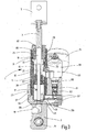
- the spring element designated as a whole by 1 has, as usual with such spring elements, a piston rod 3 which can be connected as a movable support element via a connecting part 5 to the structure of a driver's cab (not shown).
- a mounting part 7 is provided, on which (not shown) to form a bearing on the chassis of a respective vehicle a pivot point 9, see Fig. 3 , is formed.
- the piston rod 3 is formed as a hollow tube, so that a coaxially extending cavity 19 is formed for a distance measuring system 21, which will be discussed later.
- the suspension cylinder 13 forming the guide for the piston 11 extends along the spring travel provided for the piston 11 between a bottom part 23 located in the drawing and an upper end part 25.
- the suspension cylinder 13 is coaxially surrounded by a tubular body 27. which extends beyond the upper end of the suspension cylinder 13 and in the end portion an internal thread 29 (FIG. Fig. 3 ), in which the end part 25 is screwed in, wherein an O-ring 31 forms a seal on the tubular body 27.
- the end portion 25 forms at its inner end portion a support 33 for the suspension cylinder 13 to this on an inner bottom surface 35 (s. Fig. 2 ) of the bottom part 23.
- the bottom part 23 associated with the end of the tubular body 27 has an external thread 37, with which it is bolted to the bottom part 23, wherein an O-ring 38 forms the seal on the bottom part 23.
- the outer diameter of the suspension cylinder 13 is smaller than the inner diameter of a coaxial outer cylinder forming tubular body 27, so that along the outer side of the suspension cylinder 13 extending annular space 39 is formed.
- the end part 25 located at the upper end of the suspension cylinder 13 has an inwardly projecting sleeve part 41, which forms the support 33 on the suspension cylinder 13 and surrounds the piston rod 3 at a distance.
- the sleeve part 41 on radial openings 43, via which a fluid connection between the upper end of the annular space 39 and the rod-side working space 15 is formed.
- the bottom part 23 has, s. Fig. 2 and 3 , below the bottom surface 35 on a transverse channel 45, which is via passages 47 in the bottom surface 35 with the piston-side working space 17 in conjunction.
- a transverse channel 49 extending parallel to this above the transverse channel 45 is in fluid communication with the lower end 51 of the annular space 39.
- the bottom part 23 has a lateral projection 53, which forms the valve block for a damping valve 55. In operation, this creates between the transverse channels 45 and 47, which are closed by screw plugs 57 and a drain plug 59 to the outside, a fluid connection, which, depending on the valve position of the damping valve 55, more or less throttled.
- the annular space 39 therefore forms an internal connecting line for the fluid connection between the working spaces 15 and 17.
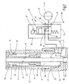
- the Fig. 2 shows the circuit of the damping valve 55 for the fluid communication between the transverse channels 45 and 49.
- the damping valve 55 is a proportional 3/2-way valve which is actuated electromagnetically by means of a magnetic coil 61, which can be excited via a plug device 63 is.
- the damping valve 55 communicates with its ports 65 and 67 with the transverse channel 49 and 45, respectively, and the third port 69 communicates with the oil side 70 of a hydropneumatic pressure accumulator 71.
- the oil side 70 is further connected via bypass lines 73 and 75, which bridge the damping valve 55, with the transverse channel 45 and the transverse channel 49, wherein in each bypass line 73, 75, a check valve 77 is inserted, each in the direction of the transverse channel 45th or 49 pressure-actuated open.
- the damping valve 55 has within the valve block formed by the projection 53 of the bottom part 23 throttle bodies, which, like the circuit of Fig. 2 can be removed, in the valve end position shown via one at each terminal 65 and 67 existing throttle body 79 connect the transverse channels 45 and 49, wherein the pressure accumulator 71 is also connected via the throttle bodies 79 with the transverse channels 45, 49 in connection.
- a connection 83 connected to the oil side 70 of the pressure accumulator 51 is provided for supplying the spring element 1 with the system pressure.
- Functional controls of the spring element 1 are possible via the connection 83 supplying P / T connections, such as load-dependent level control, roll stabilization or spring hardness, wherein the rigidity of the damping can be influenced by the dimensioning of the pressure accumulator 71.
- the check valves 77 avoid the risk of cavitation within the spring element 1 when a reduced pressure occurs during operation, by allowing a subsequent flow of fluid from the oil side 70 of the pressure accumulator 71.
- a vent hole 85 is provided with a vent screw 87 at the top of the rod-side working space 15 at the end part 25.
- damping valve 55 and pressure accumulator 71 are arranged in an inclined position to each other and the longitudinal axis, so that they, although they emanate from the valve body forming approach 53 together, to the outside of the Cling to outer cylinder forming tubular body 27.
- the inner cavity 19 of the piston rod 3 is provided for the engagement of a path-measuring system 21.
- the measuring system 21 projects in the form of a rod-like hollow body from the bottom of the bottom part 23 so far into the cavity 19, that the suspension piston 11 moves over the entire spring travel along the rod-like hollow body and within the measuring range formed by the measuring system 21.
- an opening 89 is provided in the bottom of the bottom part 23, which forms a sealed by a sealing element 93 seat for the rod-like body of the measuring system 21.
- a lateral access 91 is provided for an electrical connection and the signal transmission of the measuring system 21. How most obvious the Fig.
- FIG. 2 shows that the seat for the end of the measuring system 21 forming opening 89 in the bottom part 23 has a conically narrowing away from the working space 17 form.
- the end of the measuring system 21 is thereby pressed by the pressure in the working space 17 while reinforcing the effective sealing force on the sealing element 93 in the seat.
- a measuring system 21 may be provided a magnetostrictive linear displacement sensor series HLT 1100, as described by the company HYDAC Electronic GmbH, Hauptstr. 27, 66128 Saarmaschinen, Germany.
- the rod-like hollow body is a protective tube, in which a magnetostrictive waveguide is stretched.
- the piston 11 is provided with a permanent magnetic element forming the position sensor.
Landscapes
- Engineering & Computer Science (AREA)
- Mechanical Engineering (AREA)
- General Engineering & Computer Science (AREA)
- Chemical & Material Sciences (AREA)
- Combustion & Propulsion (AREA)
- Transportation (AREA)
- Fluid-Damping Devices (AREA)
- Vehicle Body Suspensions (AREA)
Claims (9)
- Elément de ressort, notamment élément (1) de ressort-amortisseur pour la suspension de cabine de véhicules, comme des machines mobiles, produisant du travail, comprenant un cylindre (13) de suspension à l'une des extrémités duquel est prévue une partie (23) de fond, qui forme un point (7, 9) de palier, et dans lequel un piston (11) de suspension, dont la tige (3) de piston est sortie de la partie (25) de tête, opposée à la partie (23) de fond, du cylindre (13) de suspension, sépare l'un de l'autre des espaces (15, 17) de travail pour un fluide sous pression, comme de l'huile hydraulique, les espaces (15, 17) de travail communiquant fluidiquement entre eux par un conduit (39, 45, 49, 55) de liaison, le cylindre (13) de suspension étant entouré, au moins en partie, d'un corps (27) tubulaire coaxial, dont le diamètre intérieur est plus grand que le diamètre extérieur du cylindre (13) de suspension, de manière à former, entre celui-ci et le corps (27) tubulaire, un espace (39) extérieur, qui forme au moins une partie du conduit (39, 45, 49, 55) de liaison, caractérisé en ce que, dans le conduit (39, 45, 49, 55) de liaison est insérée une soupape (55) d'amortissement, qui peut être commandée et qui forme un point (79) d'étranglement variable, en ce que la partie (23) de fond forme, par un prolongement (53) latéral, un bloc de soupape pour la soupape (55) d'amortissement et en ce que l'accumulateur (71) de pression est raccordé directement au bloc de soupape, en formant une liaison interne avec la soupape (55) d'amortissement.
- Elément de ressort suivant la revendication 1, caractérisé en ce que le corps (27) tubulaire entoure le cylindre (13) de suspension, sous la forme d'un cylindre extérieur, de manière à former, comme partie du conduit (39, 45, 49, 55) de liaison, un espace (39) annulaire s'étendant sur la longueur du cylindre (13) de suspension.
- Elément de ressort suivant l'une des revendications précédentes, caractérisé en ce que l'espace (39) extérieur, formant la partie du côté intérieur du conduit (39, 45, 49, 55) de liaison, débouche, sous la forme d'un espace annulaire, à l'extrémité loin de la partie (23) de fond du cylindre (13) de suspension, dans l'espace (15) de travail du côté de la tige et communique, à son extrémité tournée vers la partie (23) de fond, avec la soupape (55) d'amortissement.
- Elément de ressort suivant l'une des revendications précédentes, caractérisé en ce que l'espace (17) de travail, du côté du piston du cylindre (13) de suspension, communique, à son extrémité se trouvant à la partie (23) de fond, avec la soupape (55) d'amortissement.
- Elément de ressort suivant l'une des revendications précédentes, caractérisé en ce qu'il est prévu au moins un accumulateur (71) de pression hydropneumatique en communication avec les espaces (15, 17) de travail ou pouvant l'être.
- Elément de ressort suivant l'une des revendications précédentes, caractérisé en ce que le côté (70) huile, en communication avec les espaces (15, 17) de travail de l'accumulateur (71) de pression respectif, peut communiquer avec le système (83) hydraulique d'un véhicule associé.
- Elément de ressort suivant l'une des revendications précédentes, caractérisé en ce qu'il est prévue, comme soupape (55) d'amortissement, une soupape (55) à 3/2 voies proportionnelle.
- Elément de ressort suivant l'une des revendications précédentes, caractérisé en ce qu'il est prévu, entre le côté (70) huile de l'accumulateur (71) de pression respectif et l'espace (15) de travail du côté de la tige et l'espace (17) de travail du côté du piston, respectivement, un conduit (73, 75), qui contournent la soupape (55) d'amortissement et qui contiennent chacun un clapet (77) anti-retour, qui s'ouvre dans la direction allant vers l'espace (15, 17) de travail respectif.
- Elément de ressort suivant l'une des revendications précédentes, caractérisé en ce qu'il est prévu un système (21) de mesure de trajet détectant la position axiale de la tige (3) du piston dans le cylindre (13) de suspension.
Applications Claiming Priority (1)
| Application Number | Priority Date | Filing Date | Title |
|---|---|---|---|
| DE102014007641.5A DE102014007641A1 (de) | 2014-05-22 | 2014-05-22 | Federelement |
Publications (3)
| Publication Number | Publication Date |
|---|---|
| EP2952419A2 EP2952419A2 (fr) | 2015-12-09 |
| EP2952419A3 EP2952419A3 (fr) | 2016-07-06 |
| EP2952419B1 true EP2952419B1 (fr) | 2019-10-23 |
Family
ID=53039657
Family Applications (1)
| Application Number | Title | Priority Date | Filing Date |
|---|---|---|---|
| EP15001287.0A Active EP2952419B1 (fr) | 2014-05-22 | 2015-04-30 | Élément ressort amortisseur pour la suspension de cabine de véhicules |
Country Status (2)
| Country | Link |
|---|---|
| EP (1) | EP2952419B1 (fr) |
| DE (1) | DE102014007641A1 (fr) |
Families Citing this family (4)
| Publication number | Priority date | Publication date | Assignee | Title |
|---|---|---|---|---|
| JP6198601B2 (ja) * | 2013-12-20 | 2017-09-20 | Kyb株式会社 | 緩衝器 |
| DE102014013018A1 (de) | 2014-09-02 | 2016-03-03 | Hydac System Gmbh | Hydraulisches System |
| DE102018103884A1 (de) * | 2018-02-21 | 2019-08-22 | Otto Bock Healthcare Products Gmbh | Hydraulikaktuator |
| DE102019001855A1 (de) | 2019-03-15 | 2020-09-17 | Hydac Mobilhydraulik Gmbh | Feder-Dämpfer-System |
Family Cites Families (8)
| Publication number | Priority date | Publication date | Assignee | Title |
|---|---|---|---|---|
| US3807678A (en) * | 1972-09-19 | 1974-04-30 | Lord Corp | System for controlling the transmission of energy between spaced members |
| US4468050A (en) * | 1983-08-15 | 1984-08-28 | Woods Lonnie K | Computer optimized adaptive suspension system |
| US5016908A (en) * | 1989-03-13 | 1991-05-21 | Monroe Auto Equipment Company | Method and apparatus for controlling shock absorbers |
| DE3933624A1 (de) * | 1989-10-07 | 1991-04-11 | Hemscheidt Maschf Hermann | Zylinder-kolbenvorrichtung, insbesondere fuer die verwendung als stossdaempfer |
| DE4137915A1 (de) * | 1991-11-18 | 1993-05-19 | Teves Gmbh Alfred | Hydraulischer regelbarer schwingungsdaempfer |
| DE4206380A1 (de) * | 1992-02-29 | 1993-09-02 | Teves Gmbh Alfred | Daempferventil sowie verfahren zur kontinuierlichen verstellung der daempfungskraft eines regelbaren schwingungsdaempfers |
| US7234386B2 (en) * | 2005-08-26 | 2007-06-26 | Husco International, Inc. | Three chamber hydraulic cylinder for an active vehicle suspension with integrated load leveling |
| DE102007038933A1 (de) * | 2007-08-17 | 2009-02-19 | Hydac System Gmbh | Dämpfungssystem |
-
2014
- 2014-05-22 DE DE102014007641.5A patent/DE102014007641A1/de not_active Withdrawn
-
2015
- 2015-04-30 EP EP15001287.0A patent/EP2952419B1/fr active Active
Non-Patent Citations (1)
| Title |
|---|
| None * |
Also Published As
| Publication number | Publication date |
|---|---|
| DE102014007641A1 (de) | 2015-11-26 |
| EP2952419A2 (fr) | 2015-12-09 |
| EP2952419A3 (fr) | 2016-07-06 |
Similar Documents
| Publication | Publication Date | Title |
|---|---|---|
| EP2671001B1 (fr) | Ensemble piston-cylindre hydropneumatique | |
| DE102012214569B3 (de) | Luftfeder- und Dämpfereinheit mit Höhenverstellung | |
| DE102004011632B3 (de) | Federbein für Kraftfahrzeuge | |
| EP1496009B1 (fr) | Suspension hydraulique | |
| DE102007036102B4 (de) | Selbstpumpende hydropneumatische Feder-Dämpfer-Einheit | |
| EP3914463B1 (fr) | Système d'amortisseur à ressort | |
| DE102004032083B4 (de) | Feder- und Dämpfungsvorrichtung für Radaufhängungen | |
| EP1657469B1 (fr) | Amortisseur de vibrations avec force d'amortissement variable | |
| EP2952419B1 (fr) | Élément ressort amortisseur pour la suspension de cabine de véhicules | |
| DE19857595A1 (de) | Selbstpumpendes hydropneumatisches Federbein mit innerer Niveauregelung | |
| EP3840966B1 (fr) | Système d'amortisseur à ressort réglable en hauteur conçu pour un véhicule | |
| DE102005038333A1 (de) | Hydraulische Anordnung | |
| DE102013102069A1 (de) | Proportional-Wegeventil sowie hydraulische Schaltung und hydropneumatisches Federungssystem mit einem derartigen Ventil | |
| DE19731139C2 (de) | Kolben-Zylinder-Aggregat, das zwischen einem Aufbau und einem Radführungsteil eines Fahrzeugs eingebaut ist | |
| DE19959197A1 (de) | Selbstpumpendes hydropneumatisches Federbein mit innerer Niveauregelung | |
| WO2020001962A1 (fr) | Suspension de roue de véhicule avec un système de positionnement pour le pied d'un ressort porteur de carrosserie | |
| DE102005033154A1 (de) | Hydraulische Anordnung | |
| DE102010010869A1 (de) | Einrichtung zur Wankstabilisierung | |
| DE102006025826B4 (de) | Selbstpumpendes hydropneumatisches Federbein | |
| DE3925074A1 (de) | Aufhaengesystem fuer ein kraftfahrzeug | |
| EP3381721B1 (fr) | Système de suspension | |
| DE10330344A1 (de) | Hydraulische Federung | |
| DE102021212104A1 (de) | Verstellbarer Schwingungsdämpfer mit einem hydraulischen Endanschlag | |
| DE102015104489B4 (de) | Schwingungsdämpfer mit verkürzter Baulänge | |
| DE102007031525B4 (de) | Kolbenspeicher zur Dämpfung von zwei Fluidsystemen |
Legal Events
| Date | Code | Title | Description |
|---|---|---|---|
| PUAI | Public reference made under article 153(3) epc to a published international application that has entered the european phase |
Free format text: ORIGINAL CODE: 0009012 |
|
| AK | Designated contracting states |
Kind code of ref document: A2 Designated state(s): AL AT BE BG CH CY CZ DE DK EE ES FI FR GB GR HR HU IE IS IT LI LT LU LV MC MK MT NL NO PL PT RO RS SE SI SK SM TR |
|
| AX | Request for extension of the european patent |
Extension state: BA ME |
|
| PUAL | Search report despatched |
Free format text: ORIGINAL CODE: 0009013 |
|
| AK | Designated contracting states |
Kind code of ref document: A3 Designated state(s): AL AT BE BG CH CY CZ DE DK EE ES FI FR GB GR HR HU IE IS IT LI LT LU LV MC MK MT NL NO PL PT RO RS SE SI SK SM TR |
|
| AX | Request for extension of the european patent |
Extension state: BA ME |
|
| RIC1 | Information provided on ipc code assigned before grant |
Ipc: B60G 17/08 20060101ALI20160602BHEP Ipc: B62D 33/06 20060101AFI20160602BHEP |
|
| 17P | Request for examination filed |
Effective date: 20160714 |
|
| RAP1 | Party data changed (applicant data changed or rights of an application transferred) |
Owner name: HYDAC SYSTEMS & SERVICES GMBH |
|
| RIC1 | Information provided on ipc code assigned before grant |
Ipc: B60G 17/08 20060101ALI20181004BHEP Ipc: B62D 33/06 20060101AFI20181004BHEP |
|
| STAA | Information on the status of an ep patent application or granted ep patent |
Free format text: STATUS: EXAMINATION IS IN PROGRESS |
|
| 17Q | First examination report despatched |
Effective date: 20181113 |
|
| GRAP | Despatch of communication of intention to grant a patent |
Free format text: ORIGINAL CODE: EPIDOSNIGR1 |
|
| STAA | Information on the status of an ep patent application or granted ep patent |
Free format text: STATUS: GRANT OF PATENT IS INTENDED |
|
| INTG | Intention to grant announced |
Effective date: 20190619 |
|
| GRAS | Grant fee paid |
Free format text: ORIGINAL CODE: EPIDOSNIGR3 |
|
| GRAA | (expected) grant |
Free format text: ORIGINAL CODE: 0009210 |
|
| STAA | Information on the status of an ep patent application or granted ep patent |
Free format text: STATUS: THE PATENT HAS BEEN GRANTED |
|
| AK | Designated contracting states |
Kind code of ref document: B1 Designated state(s): AL AT BE BG CH CY CZ DE DK EE ES FI FR GB GR HR HU IE IS IT LI LT LU LV MC MK MT NL NO PL PT RO RS SE SI SK SM TR |
|
| REG | Reference to a national code |
Ref country code: GB Ref legal event code: FG4D Free format text: NOT ENGLISH |
|
| REG | Reference to a national code |
Ref country code: CH Ref legal event code: EP |
|
| REG | Reference to a national code |
Ref country code: IE Ref legal event code: FG4D Free format text: LANGUAGE OF EP DOCUMENT: GERMAN |
|
| REG | Reference to a national code |
Ref country code: DE Ref legal event code: R096 Ref document number: 502015010701 Country of ref document: DE |
|
| REG | Reference to a national code |
Ref country code: AT Ref legal event code: REF Ref document number: 1193340 Country of ref document: AT Kind code of ref document: T Effective date: 20191115 |
|
| REG | Reference to a national code |
Ref country code: NL Ref legal event code: MP Effective date: 20191023 |
|
| REG | Reference to a national code |
Ref country code: LT Ref legal event code: MG4D |
|
| PG25 | Lapsed in a contracting state [announced via postgrant information from national office to epo] |
Ref country code: ES Free format text: LAPSE BECAUSE OF FAILURE TO SUBMIT A TRANSLATION OF THE DESCRIPTION OR TO PAY THE FEE WITHIN THE PRESCRIBED TIME-LIMIT Effective date: 20191023 Ref country code: PL Free format text: LAPSE BECAUSE OF FAILURE TO SUBMIT A TRANSLATION OF THE DESCRIPTION OR TO PAY THE FEE WITHIN THE PRESCRIBED TIME-LIMIT Effective date: 20191023 Ref country code: NO Free format text: LAPSE BECAUSE OF FAILURE TO SUBMIT A TRANSLATION OF THE DESCRIPTION OR TO PAY THE FEE WITHIN THE PRESCRIBED TIME-LIMIT Effective date: 20200123 Ref country code: LV Free format text: LAPSE BECAUSE OF FAILURE TO SUBMIT A TRANSLATION OF THE DESCRIPTION OR TO PAY THE FEE WITHIN THE PRESCRIBED TIME-LIMIT Effective date: 20191023 Ref country code: SE Free format text: LAPSE BECAUSE OF FAILURE TO SUBMIT A TRANSLATION OF THE DESCRIPTION OR TO PAY THE FEE WITHIN THE PRESCRIBED TIME-LIMIT Effective date: 20191023 Ref country code: BG Free format text: LAPSE BECAUSE OF FAILURE TO SUBMIT A TRANSLATION OF THE DESCRIPTION OR TO PAY THE FEE WITHIN THE PRESCRIBED TIME-LIMIT Effective date: 20200123 Ref country code: FI Free format text: LAPSE BECAUSE OF FAILURE TO SUBMIT A TRANSLATION OF THE DESCRIPTION OR TO PAY THE FEE WITHIN THE PRESCRIBED TIME-LIMIT Effective date: 20191023 Ref country code: GR Free format text: LAPSE BECAUSE OF FAILURE TO SUBMIT A TRANSLATION OF THE DESCRIPTION OR TO PAY THE FEE WITHIN THE PRESCRIBED TIME-LIMIT Effective date: 20200124 Ref country code: PT Free format text: LAPSE BECAUSE OF FAILURE TO SUBMIT A TRANSLATION OF THE DESCRIPTION OR TO PAY THE FEE WITHIN THE PRESCRIBED TIME-LIMIT Effective date: 20200224 Ref country code: LT Free format text: LAPSE BECAUSE OF FAILURE TO SUBMIT A TRANSLATION OF THE DESCRIPTION OR TO PAY THE FEE WITHIN THE PRESCRIBED TIME-LIMIT Effective date: 20191023 Ref country code: NL Free format text: LAPSE BECAUSE OF FAILURE TO SUBMIT A TRANSLATION OF THE DESCRIPTION OR TO PAY THE FEE WITHIN THE PRESCRIBED TIME-LIMIT Effective date: 20191023 |
|
| PG25 | Lapsed in a contracting state [announced via postgrant information from national office to epo] |
Ref country code: RS Free format text: LAPSE BECAUSE OF FAILURE TO SUBMIT A TRANSLATION OF THE DESCRIPTION OR TO PAY THE FEE WITHIN THE PRESCRIBED TIME-LIMIT Effective date: 20191023 Ref country code: HR Free format text: LAPSE BECAUSE OF FAILURE TO SUBMIT A TRANSLATION OF THE DESCRIPTION OR TO PAY THE FEE WITHIN THE PRESCRIBED TIME-LIMIT Effective date: 20191023 Ref country code: IS Free format text: LAPSE BECAUSE OF FAILURE TO SUBMIT A TRANSLATION OF THE DESCRIPTION OR TO PAY THE FEE WITHIN THE PRESCRIBED TIME-LIMIT Effective date: 20200224 |
|
| PG25 | Lapsed in a contracting state [announced via postgrant information from national office to epo] |
Ref country code: AL Free format text: LAPSE BECAUSE OF FAILURE TO SUBMIT A TRANSLATION OF THE DESCRIPTION OR TO PAY THE FEE WITHIN THE PRESCRIBED TIME-LIMIT Effective date: 20191023 |
|
| REG | Reference to a national code |
Ref country code: DE Ref legal event code: R097 Ref document number: 502015010701 Country of ref document: DE |
|
| PG2D | Information on lapse in contracting state deleted |
Ref country code: IS |
|
| PG25 | Lapsed in a contracting state [announced via postgrant information from national office to epo] |
Ref country code: CZ Free format text: LAPSE BECAUSE OF FAILURE TO SUBMIT A TRANSLATION OF THE DESCRIPTION OR TO PAY THE FEE WITHIN THE PRESCRIBED TIME-LIMIT Effective date: 20191023 Ref country code: RO Free format text: LAPSE BECAUSE OF FAILURE TO SUBMIT A TRANSLATION OF THE DESCRIPTION OR TO PAY THE FEE WITHIN THE PRESCRIBED TIME-LIMIT Effective date: 20191023 Ref country code: EE Free format text: LAPSE BECAUSE OF FAILURE TO SUBMIT A TRANSLATION OF THE DESCRIPTION OR TO PAY THE FEE WITHIN THE PRESCRIBED TIME-LIMIT Effective date: 20191023 Ref country code: DK Free format text: LAPSE BECAUSE OF FAILURE TO SUBMIT A TRANSLATION OF THE DESCRIPTION OR TO PAY THE FEE WITHIN THE PRESCRIBED TIME-LIMIT Effective date: 20191023 Ref country code: IS Free format text: LAPSE BECAUSE OF FAILURE TO SUBMIT A TRANSLATION OF THE DESCRIPTION OR TO PAY THE FEE WITHIN THE PRESCRIBED TIME-LIMIT Effective date: 20200223 |
|
| PLBE | No opposition filed within time limit |
Free format text: ORIGINAL CODE: 0009261 |
|
| STAA | Information on the status of an ep patent application or granted ep patent |
Free format text: STATUS: NO OPPOSITION FILED WITHIN TIME LIMIT |
|
| PG25 | Lapsed in a contracting state [announced via postgrant information from national office to epo] |
Ref country code: SK Free format text: LAPSE BECAUSE OF FAILURE TO SUBMIT A TRANSLATION OF THE DESCRIPTION OR TO PAY THE FEE WITHIN THE PRESCRIBED TIME-LIMIT Effective date: 20191023 Ref country code: SM Free format text: LAPSE BECAUSE OF FAILURE TO SUBMIT A TRANSLATION OF THE DESCRIPTION OR TO PAY THE FEE WITHIN THE PRESCRIBED TIME-LIMIT Effective date: 20191023 |
|
| 26N | No opposition filed |
Effective date: 20200724 |
|
| PG25 | Lapsed in a contracting state [announced via postgrant information from national office to epo] |
Ref country code: MC Free format text: LAPSE BECAUSE OF FAILURE TO SUBMIT A TRANSLATION OF THE DESCRIPTION OR TO PAY THE FEE WITHIN THE PRESCRIBED TIME-LIMIT Effective date: 20191023 Ref country code: SI Free format text: LAPSE BECAUSE OF FAILURE TO SUBMIT A TRANSLATION OF THE DESCRIPTION OR TO PAY THE FEE WITHIN THE PRESCRIBED TIME-LIMIT Effective date: 20191023 |
|
| REG | Reference to a national code |
Ref country code: CH Ref legal event code: PL |
|
| PG25 | Lapsed in a contracting state [announced via postgrant information from national office to epo] |
Ref country code: CH Free format text: LAPSE BECAUSE OF NON-PAYMENT OF DUE FEES Effective date: 20200430 Ref country code: LU Free format text: LAPSE BECAUSE OF NON-PAYMENT OF DUE FEES Effective date: 20200430 Ref country code: LI Free format text: LAPSE BECAUSE OF NON-PAYMENT OF DUE FEES Effective date: 20200430 |
|
| REG | Reference to a national code |
Ref country code: BE Ref legal event code: MM Effective date: 20200430 |
|
| PG25 | Lapsed in a contracting state [announced via postgrant information from national office to epo] |
Ref country code: BE Free format text: LAPSE BECAUSE OF NON-PAYMENT OF DUE FEES Effective date: 20200430 |
|
| PG25 | Lapsed in a contracting state [announced via postgrant information from national office to epo] |
Ref country code: IE Free format text: LAPSE BECAUSE OF NON-PAYMENT OF DUE FEES Effective date: 20200430 |
|
| PG25 | Lapsed in a contracting state [announced via postgrant information from national office to epo] |
Ref country code: TR Free format text: LAPSE BECAUSE OF FAILURE TO SUBMIT A TRANSLATION OF THE DESCRIPTION OR TO PAY THE FEE WITHIN THE PRESCRIBED TIME-LIMIT Effective date: 20191023 Ref country code: MT Free format text: LAPSE BECAUSE OF FAILURE TO SUBMIT A TRANSLATION OF THE DESCRIPTION OR TO PAY THE FEE WITHIN THE PRESCRIBED TIME-LIMIT Effective date: 20191023 Ref country code: CY Free format text: LAPSE BECAUSE OF FAILURE TO SUBMIT A TRANSLATION OF THE DESCRIPTION OR TO PAY THE FEE WITHIN THE PRESCRIBED TIME-LIMIT Effective date: 20191023 |
|
| PG25 | Lapsed in a contracting state [announced via postgrant information from national office to epo] |
Ref country code: MK Free format text: LAPSE BECAUSE OF FAILURE TO SUBMIT A TRANSLATION OF THE DESCRIPTION OR TO PAY THE FEE WITHIN THE PRESCRIBED TIME-LIMIT Effective date: 20191023 |
|
| PGFP | Annual fee paid to national office [announced via postgrant information from national office to epo] |
Ref country code: FR Payment date: 20250317 Year of fee payment: 11 |
|
| PGFP | Annual fee paid to national office [announced via postgrant information from national office to epo] |
Ref country code: DE Payment date: 20250430 Year of fee payment: 11 |
|
| PGFP | Annual fee paid to national office [announced via postgrant information from national office to epo] |
Ref country code: IT Payment date: 20250407 Year of fee payment: 11 |
|
| PGFP | Annual fee paid to national office [announced via postgrant information from national office to epo] |
Ref country code: AT Payment date: 20250404 Year of fee payment: 11 |
|
| PGFP | Annual fee paid to national office [announced via postgrant information from national office to epo] |
Ref country code: GB Payment date: 20260210 Year of fee payment: 12 |