EP2952470A1 - Trémie dotée de gobelet gradué - Google Patents
Trémie dotée de gobelet gradué Download PDFInfo
- Publication number
- EP2952470A1 EP2952470A1 EP14171621.7A EP14171621A EP2952470A1 EP 2952470 A1 EP2952470 A1 EP 2952470A1 EP 14171621 A EP14171621 A EP 14171621A EP 2952470 A1 EP2952470 A1 EP 2952470A1
- Authority
- EP
- European Patent Office
- Prior art keywords
- funnel
- measuring cup
- filling
- hopper
- edge
- Prior art date
- Legal status (The legal status is an assumption and is not a legal conclusion. Google has not performed a legal analysis and makes no representation as to the accuracy of the status listed.)
- Withdrawn
Links
- 239000007788 liquid Substances 0.000 claims description 26
- 238000003780 insertion Methods 0.000 claims description 12
- 230000037431 insertion Effects 0.000 claims description 12
- 239000013590 bulk material Substances 0.000 claims description 7
- 239000011362 coarse particle Substances 0.000 claims description 2
- 239000000945 filler Substances 0.000 description 6
- 239000000344 soap Substances 0.000 description 2
- 230000015572 biosynthetic process Effects 0.000 description 1
- 239000002131 composite material Substances 0.000 description 1
- 238000011161 development Methods 0.000 description 1
- 230000018109 developmental process Effects 0.000 description 1
- 238000007865 diluting Methods 0.000 description 1
- 235000013399 edible fruits Nutrition 0.000 description 1
- 230000000694 effects Effects 0.000 description 1
- 239000003337 fertilizer Substances 0.000 description 1
- 235000013305 food Nutrition 0.000 description 1
- 238000007373 indentation Methods 0.000 description 1
- 239000003621 irrigation water Substances 0.000 description 1
- 239000011344 liquid material Substances 0.000 description 1
- 230000007774 longterm Effects 0.000 description 1
- 230000014759 maintenance of location Effects 0.000 description 1
- 239000000463 material Substances 0.000 description 1
- 239000010705 motor oil Substances 0.000 description 1
- 239000003921 oil Substances 0.000 description 1
- 235000015205 orange juice Nutrition 0.000 description 1
- 239000002245 particle Substances 0.000 description 1
- 230000002093 peripheral effect Effects 0.000 description 1
- 230000000717 retained effect Effects 0.000 description 1
- 239000006188 syrup Substances 0.000 description 1
- 235000020357 syrup Nutrition 0.000 description 1
Images


Classifications
-
- B—PERFORMING OPERATIONS; TRANSPORTING
- B67—OPENING, CLOSING OR CLEANING BOTTLES, JARS OR SIMILAR CONTAINERS; LIQUID HANDLING
- B67C—CLEANING, FILLING WITH LIQUIDS OR SEMILIQUIDS, OR EMPTYING, OF BOTTLES, JARS, CANS, CASKS, BARRELS, OR SIMILAR CONTAINERS, NOT OTHERWISE PROVIDED FOR; FUNNELS
- B67C11/00—Funnels, e.g. for liquids
- B67C11/02—Funnels, e.g. for liquids without discharge valves
-
- G—PHYSICS
- G01—MEASURING; TESTING
- G01F—MEASURING VOLUME, VOLUME FLOW, MASS FLOW OR LIQUID LEVEL; METERING BY VOLUME
- G01F19/00—Calibrated capacity measures for fluids or fluent solid material, e.g. measuring cups
- G01F19/002—Measuring spoons or scoops
-
- B—PERFORMING OPERATIONS; TRANSPORTING
- B67—OPENING, CLOSING OR CLEANING BOTTLES, JARS OR SIMILAR CONTAINERS; LIQUID HANDLING
- B67C—CLEANING, FILLING WITH LIQUIDS OR SEMILIQUIDS, OR EMPTYING, OF BOTTLES, JARS, CANS, CASKS, BARRELS, OR SIMILAR CONTAINERS, NOT OTHERWISE PROVIDED FOR; FUNNELS
- B67C11/00—Funnels, e.g. for liquids
- B67C2011/40—Funnels, e.g. for liquids comprising level indicating means
Definitions
- the invention relates to a funnel with an outlet region and a filling region, wherein the filling region is delimited by a peripheral funnel edge and the funnel tapers from the filling region to the outlet region.
- the invention relates to such a funnel made of plastic for household and kitchen.
- Funnels of the present type can be designed in a variety of forms, for example in the form of a cone, or, as usual in household funnels in the form of second composite truncated cones, wherein the outlet area a narrow cone shape to form a shaft and the filling a wide cone shape to form the largest possible Owns opening.
- the latter is also the preferred form of funnel from which the present invention is based.
- other shapes for the hopper are conceivable, in particular forms whose cross-section is not circular.
- Funnels of the present type are generally used for filling liquids in containers and other containers with small openings or filler neck. In addition, they can also be used for other bulk materials, such as small or granular foods.
- liquids In the preferred field of use of hoppers of the present type, ie in the home and kitchen, liquids must often be filled into containers in a certain amount, for example when baking, when mixing drinks, when diluting syrup, when refilling liquid soap into a soap dispenser, when Dosing fertilizer in irrigation water, refilling engine oil, mixing oil and gasoline for the lawnmower, and the like.
- a measuring cup is usually used in which the desired Amount of liquid is measured, and from this this amount of liquid is then poured into the hopper.
- the present invention is therefore an object of the invention to improve a funnel of the type mentioned in terms of its applicability during filling of certain amounts of liquids or bulk material.
- a measuring cup is provided which is arranged in the filling area of the funnel.
- This measuring cup can be a separate part which can be inserted into the filling area of the funnel, but it can also be firmly connected to the filling area of the funnel.
- the combination according to the invention of a funnel with a measuring cup first ensures that measuring cups and funnels are stored together and, consequently, can be provided with a handle. Furthermore, the measuring cup according to the invention, even if it can be removed as a separate part of the filling of the hopper and reinserted in this, at least when it is inserted in the filling of the hopper, an integral Part of the funnel, so that the funnel can be attached to the already metered amount of bulk material or liquid to a slightly inaccessible filler neck. There is therefore no room for a measuring cup above the funnel in this difficult-to-access area in order to be able to pour the liquid out of the measuring cup into the funnel. Rather, the measuring cup can be emptied or opened within the filling of the hopper, which facilitates handling, especially in confined spaces.
- the measuring cup is movably arranged in the filling area of the hopper, in particular by a movable storage in the filling area or at the hopper edge.
- This movable arrangement allows the liquid contained in the measuring cup or the bulk material within the hopper can be poured into this.
- this measure is easier, long-term stable and less susceptible to interference.
- two approximately diametrically opposed pivot bearing elements can be arranged on the hopper edge or in the filling area of the hopper, in particular bearing journals or bearing bushes, while the measuring cup has matching counter bearing elements, correspondingly bearing bushes or bearing journals.
- the pivot bearing elements and the abutment elements of the measuring cup is then pivotally mounted in the filling of the hopper, with a pivot axis which extends through or over the filling area.
- the pivot axis preferably extends approximately centrally above or within the filling region, so that the measuring cup can be pivoted about this pivoting axis in order to deliver its contents into the filling region of the funnel.
- the pivoting of the measuring cup in the filling of the hopper is also advantageous if the funnel inclined to a filler neck or must be used in these; because the measuring cup can then be pivoted about the pivot axis so that it is not tilted despite the inclination of the funnel, as long as its content is not yet to be delivered into the filling of the funnel.
- the measuring cup is provided in the region of its counter-bearing elements with upwardly projecting tabs to the measuring cup for insertion into the pivot bearing elements of the funnel or for removal from the pivot bearing elements to be able to deform.
- the two protruding tabs of the measuring cup can be easily compressed and deformed so that the counter-bearing elements from the pivot bearing elements solve, especially if they are designed as a journal and bushings.
- the measuring cup can be easily removed from the filling area of the funnel and just as easily be reinserted into it, although it is still releasably, but permanently connected to the funnel and becomes an integral part of the same.
- the pivot bearing elements can then, if they are arranged on the hopper edge, also consist of upwardly open bearing shells, while the counter-bearing elements are formed on the measuring cup as bearing pins which can be inserted into these bearings and removed from them. Deformation of the measuring cup for insertion or removal is then not necessary.
- the upwardly open bearing shells are provided on their open side in such a way with a narrowing that the bearing pins of the measuring cup can be snapped into the bearing shells.
- the measuring cup is provided with a scale which allows reading of a volume of liquid or bulk material in the measuring cup at different inclinations of the measuring cup.
- scales which usually consist of a series of elongated strokes which describe a curve towards a pouring edge, are known per se in measuring cups. These known scales allow the reading of the level of a liquid in a measuring cup even during the dispensing of the liquid.
- the corresponding scale should also compensate for any inclination of the funnel when measuring a liquid or a bulk material in the measuring cup.
- the filling area of the funnel according to the invention as well as the measuring cup are each formed approximately hemispherical.
- a pivotable mounting of the measuring cup about a pivot axis which runs diametrically over the hopper edge such a configuration of the hopper according to the invention enables the measuring cup to have an optimum volume in relation to the outside dimensions of the hopper for measuring liquids or bulk material.
- the edge of the measuring cup always runs independently of its pivot angle within the filling of the funnel always approximately at a constant distance from the inner surface of the filling, so that the structured rim of the measuring cup can achieve its intended retention effect for particles until the measuring cup is completely poured out.
- the outlet area of the funnel is preferably in the form of a stalk which is remote from the filling area, the filling area expanding conically up to the hopper edge starting from the shank.
- the measuring cup In order to be able to better handle the measuring cup as a separate part when it is made removable from the filling area of the funnel it is preferred if it has a flattened bottom for parking on a flat surface.
- a handle element is arranged, which projects beyond the hopper edge, when the measuring cup is inserted into the filling of the hopper.
- this handle element of the measuring cup can then be easily pivoted to pour its contents.
- a latching element for latching receiving the gripping element of the measuring cup is provided in the hopper edge, so that it is firmly integrated in the normal state in the filling of the hopper.
- an additional insertion funnel is provided, which is inserted between the filling area of the funnel and the measuring cup.
- the result is a three-piece device that can be stored together and provided with a handle. By removing the measuring cup from the filling area of the funnel, the insertion funnel is released and can also be removed.
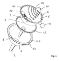
- Both embodiments shown in the figures comprise the actual funnel portion of the funnel according to the invention with a filling region 1 and an outlet region 2.
- the outlet region 2 is formed as a truncated cone and forms a shank that is offset from the filling region 1 and can be inserted into a filler neck or a vessel ,
- the filling area 1 has the shape of a spherical shell and is hemispherical in shape. It widens conically starting from the outlet region 2 to a funnel edge 3. This funnel edge 3 is presently provided with a projection 4.
- a measuring cup 5 inserted into the filling area 1 of the funnel.
- This measuring cup 5 has, in particular FIG. 2 illustrates, also the shape of a spherical shell and is, as well as the filling area 1 of the funnel, hemispherical shaped with a likewise projecting edge 6.
- the measuring cup 5 and the filling area 1 of the funnel are formed in such a spherical shell-shaped, that the measuring cup 5 all around a small distance to the filling area 1 of the hopper complies with and is included in this.
- the measuring cup 5 has a flattened bottom 7 for parking on a flat surface. logically the measuring cup 5 can be removed from the filling area 1 of the funnel and used again in this.
- the connection between the measuring cup 5 and the filling area 1 of the funnel takes place via two bearing bushes arranged diametrically opposite one another on the funnel edge 3 as pivot bearing elements 8 and two engaging into these bearing bushes, in FIG FIG. 4
- two tabs 10 at the edge 6 of the measuring cup 5 this can be compressed and consequently deformed so that the bearing pin or abutment elements 9 from their engagement from the bearing bushes or pivot bearing elements 8 in Loosen funnel edge 3, so that the measuring cup 5 can be taken out of the filling area 1 of the funnel.
- the measuring cup 5 can be used again in the filling area 1.
- the measuring cup 5 is firmly connected to the filling area 1 of the hopper and forms an integral unit therewith.
- the measuring cup 5 By means of the pivot bearing elements 8 and the abutment elements 9 is the measuring cup 5, in particular FIG. 2 illustrated, pivotable about a diametrically extending over the filling area 1 pivot axis.
- this pivot axis runs approximately through the center of the two balls, which ingeniously complete the hemispherical spherical shells of the measuring cup 5 and the filling area 1.
- the pivoting of the measuring cup 5 about the pivot axis does not cause the distance between the measuring cup and the filling region 1 to change during pivoting; this remains unchanged during the entire pivoting movement.
- the pivoting of the measuring cup 5 in the filling area 1 around the pivot axis defined by the abutment elements 9 is facilitated by a gripping element 12 which, like FIG. 1 shows over the hopper edge 3 and can be easily grasped by the user.
- the grip element 12 is firmly connected to the edge 6 of the measuring cup 5.
- the funnel edge 3 has an indentation as a latching element 13, into which the gripping element 12 can be pressed into latching manner (FIG. FIG. 1 ).
- the measuring cup 5 can not inadvertently pivot within the filling area 1 of the funnel, but sits firmly in this.
- the measuring cup 5 is provided on its inner side with a scale 14 on which the volume of liquid 16 located in the measuring cup 5 can be read.
- This scale 14 has graduated lines which run in a curve towards the edge 6 of the measuring cup 5 so that the level or the volume of the liquid 16 in the measuring cup 5 can be read even when the measuring cup is pivoted ( FIG. 3 ).
- FIG. 5 shows a second embodiment of a funnel, which differs from the first embodiment, in the FIGS. 1 to 4 is distinguished by the additional presence of an insertion funnel 15.
- the insertion funnel 15 is seated between the filling area 1 of the funnel and the measuring cup 5 inserted therein and can be removed when the measuring cup 5 is taken out of the filling area 1 of the funnel. Since the measuring cup 5 is normally firmly seated in the pivot bearing elements 8 and in the latching element 13 in the present embodiment, the insertion funnel is 15 captive integrated and can be separated at any time to use it for filler neck or bottle openings for which the outlet area 2 of the actual funnel is too wide.
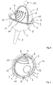
- FIGS. 6 and 7 is shown as a third embodiment, a funnel, which differs from the embodiments of the FIGS. 1 to 5 especially distinguished by the connection between the measuring cup 5 and the filling area 1 of the funnel.
- the pivot bearing elements 8 are also arranged on the hopper edge 3, but not designed as a bearing bushes, but as upwardly open bearing shells.
- the measuring cup 5 has, as an abutment element 9, two bearing pins suitable for insertion into the bearing shells, so that the measuring cup 5 is easily inserted into the filling region 1 of the funnel ( FIG. 7 ) and can be taken out just as easily ( FIG. 6 ). For this purpose, it is not necessary to deform the measuring cup 5. Accordingly, this third embodiment differs from the two preceding embodiments also by the absence of the tabs 10 on the edge 6 of the measuring cup fifth
- the trained in the third embodiment as a bearing shells pivot bearing elements 8 on the hopper edge 3 may, if necessary, be formed so that the counter-bearing elements formed as a bearing pins 9 can be inserted into the bearing shells latching on the edge 6 of the measuring cup 5.
- a liquid to be filled 16 can be measured in the measuring cup 5 and poured by a pivotal movement of the measuring cup 5 lossless in the filling area 1 of the funnel, after which the liquid 16 via the outlet region 2 of the funnel into a (not shown) filler neck a vessel or the like can flow.
- the measuring cup 5 has a flattened Floor 7 as a stand area.
- the hopper according to the invention can be expanded with a smaller insertion hopper 15, which can be inserted into the outlet region 2, and is held stationary by the measuring cup 5 inserted into the filling region 1.
Landscapes
- Physics & Mathematics (AREA)
- Fluid Mechanics (AREA)
- General Physics & Mathematics (AREA)
- Filling Of Jars Or Cans And Processes For Cleaning And Sealing Jars (AREA)
Priority Applications (1)
| Application Number | Priority Date | Filing Date | Title |
|---|---|---|---|
| EP14171621.7A EP2952470A1 (fr) | 2014-06-06 | 2014-06-06 | Trémie dotée de gobelet gradué |
Applications Claiming Priority (1)
| Application Number | Priority Date | Filing Date | Title |
|---|---|---|---|
| EP14171621.7A EP2952470A1 (fr) | 2014-06-06 | 2014-06-06 | Trémie dotée de gobelet gradué |
Publications (1)
| Publication Number | Publication Date |
|---|---|
| EP2952470A1 true EP2952470A1 (fr) | 2015-12-09 |
Family
ID=50932993
Family Applications (1)
| Application Number | Title | Priority Date | Filing Date |
|---|---|---|---|
| EP14171621.7A Withdrawn EP2952470A1 (fr) | 2014-06-06 | 2014-06-06 | Trémie dotée de gobelet gradué |
Country Status (1)
| Country | Link |
|---|---|
| EP (1) | EP2952470A1 (fr) |
Cited By (1)
| Publication number | Priority date | Publication date | Assignee | Title |
|---|---|---|---|---|
| WO2023016659A1 (fr) * | 2021-08-13 | 2023-02-16 | MAX-PLANCK-Gesellschaft zur Förderung der Wissenschaften e.V. | Dispositif de distribution de billes et de poudre |
Citations (6)
| Publication number | Priority date | Publication date | Assignee | Title |
|---|---|---|---|---|
| FR540897A (fr) * | 1921-05-04 | 1922-07-19 | Entonnoir mesureur | |
| DE9112224U1 (de) * | 1991-10-01 | 1991-11-28 | Werbeform GmbH Display-Werk, 6149 Fürth | Trichter |
| US20090178729A1 (en) * | 2008-01-14 | 2009-07-16 | Guy Ben Zur | Device for transfer of substances between containers |
| US20120324997A1 (en) * | 2011-06-22 | 2012-12-27 | Bruce Mitchell Tharp | Measuring cup |
| US20130119093A1 (en) * | 2011-11-14 | 2013-05-16 | Susan A. Thomson | Gathering and Dispensing Scoop with Gate Valve |
| US20140083555A1 (en) * | 2012-09-26 | 2014-03-27 | Jarred Loran Allen | Combination scoop and funnel |
-
2014
- 2014-06-06 EP EP14171621.7A patent/EP2952470A1/fr not_active Withdrawn
Patent Citations (6)
| Publication number | Priority date | Publication date | Assignee | Title |
|---|---|---|---|---|
| FR540897A (fr) * | 1921-05-04 | 1922-07-19 | Entonnoir mesureur | |
| DE9112224U1 (de) * | 1991-10-01 | 1991-11-28 | Werbeform GmbH Display-Werk, 6149 Fürth | Trichter |
| US20090178729A1 (en) * | 2008-01-14 | 2009-07-16 | Guy Ben Zur | Device for transfer of substances between containers |
| US20120324997A1 (en) * | 2011-06-22 | 2012-12-27 | Bruce Mitchell Tharp | Measuring cup |
| US20130119093A1 (en) * | 2011-11-14 | 2013-05-16 | Susan A. Thomson | Gathering and Dispensing Scoop with Gate Valve |
| US20140083555A1 (en) * | 2012-09-26 | 2014-03-27 | Jarred Loran Allen | Combination scoop and funnel |
Cited By (1)
| Publication number | Priority date | Publication date | Assignee | Title |
|---|---|---|---|---|
| WO2023016659A1 (fr) * | 2021-08-13 | 2023-02-16 | MAX-PLANCK-Gesellschaft zur Förderung der Wissenschaften e.V. | Dispositif de distribution de billes et de poudre |
Similar Documents
| Publication | Publication Date | Title |
|---|---|---|
| CH700865B1 (de) | Vorrichtung zur Dosierung pulverförmiger Substanzen. | |
| DE202016103908U1 (de) | Dosiervorrichtung | |
| DE102019125582B4 (de) | System zur Herstellung von Mixgetränken | |
| DE8717773U1 (de) | Vorrichtung mit wenigstens einem Aufnahmebehälter zur Aufbewahrung und Abgabe eines Stoffes | |
| EP1931952B1 (fr) | Dispositif de dosage pour substances pulverulentes ou pateuses | |
| EP2952470A1 (fr) | Trémie dotée de gobelet gradué | |
| DE202010014281U1 (de) | Deckel für Getränkebehälter | |
| DE19917652C2 (de) | Vorrichtung zum Portionieren fester oder flüssiger Stoffe | |
| EP2742830A2 (fr) | Récipient comprenant un dispositif programmable de dosage de sucre ou de sel | |
| EP3339817B1 (fr) | Dispositif de dosage pour substances en poudre | |
| DE4242577C2 (de) | Abgabevorrichtung für fließfähige Medien | |
| AT221016B (de) | Behälter | |
| EP3636116B1 (fr) | Gobelet de matière plastique moulée par injection | |
| DE947430C (de) | Vorrichtung zur begrenzten Abgabe von schuettfaehigem Gut aus einem Behaelter | |
| DE2052051A1 (de) | Behälter mit Dosiereinrichtung für rieselfähige pulvrige bis körnige Feststoffe | |
| DE3401281C2 (de) | Vorrichtung zur dosierten, insbesondere portionierten Abgabe von feinverteiltem Gut | |
| DE202007014693U1 (de) | Verschluss mit Aufnahmeraum | |
| DE2613757A1 (de) | Duesenaggregat zur abgabe eines fliessfaehigen feststoffes aus einem behaelter, insbesondere fuer heissgetraenke-automaten | |
| DE202018103673U1 (de) | Dosier-Verpackung für rieselfähiges oder flüssiges Füllgut | |
| DE1953792A1 (de) | Behaelter mit einer Abmesskammer zur quantitativen Abmessung von koernigem Material od.dgl. | |
| DE920413C (de) | Verpackungsdose | |
| DE3242761A1 (de) | Dosiervorrichtung | |
| DE102022112180A1 (de) | Dosierstation für ein Wasch- oder Reinigungsmittel sowie Verfahren zum Bereitstellen des Wasch- oder Reinigungsmittels | |
| EP2896305A1 (fr) | Cendrier | |
| DE593056C (de) | Milchkanne mit angebautem Messgefaess |
Legal Events
| Date | Code | Title | Description |
|---|---|---|---|
| PUAI | Public reference made under article 153(3) epc to a published international application that has entered the european phase |
Free format text: ORIGINAL CODE: 0009012 |
|
| AK | Designated contracting states |
Kind code of ref document: A1 Designated state(s): AL AT BE BG CH CY CZ DE DK EE ES FI FR GB GR HR HU IE IS IT LI LT LU LV MC MK MT NL NO PL PT RO RS SE SI SK SM TR |
|
| AX | Request for extension of the european patent |
Extension state: BA ME |
|
| STAA | Information on the status of an ep patent application or granted ep patent |
Free format text: STATUS: THE APPLICATION IS DEEMED TO BE WITHDRAWN |
|
| 18D | Application deemed to be withdrawn |
Effective date: 20160610 |