EP2952783A1 - System und verfahren zur steuerung von schaltungen eines elektronisch gesteuerten mechanischen getriebes eines fahrzeugs - Google Patents
System und verfahren zur steuerung von schaltungen eines elektronisch gesteuerten mechanischen getriebes eines fahrzeugs Download PDFInfo
- Publication number
- EP2952783A1 EP2952783A1 EP15170857.5A EP15170857A EP2952783A1 EP 2952783 A1 EP2952783 A1 EP 2952783A1 EP 15170857 A EP15170857 A EP 15170857A EP 2952783 A1 EP2952783 A1 EP 2952783A1
- Authority
- EP
- European Patent Office
- Prior art keywords
- motor
- pump
- transmission
- gear
- vehicle
- Prior art date
- Legal status (The legal status is an assumption and is not a legal conclusion. Google has not performed a legal analysis and makes no representation as to the accuracy of the status listed.)
- Withdrawn
Links
- 238000000034 method Methods 0.000 title claims abstract description 27
- 230000009347 mechanical transmission Effects 0.000 title description 8
- 230000005540 biological transmission Effects 0.000 claims abstract description 68
- 238000006073 displacement reaction Methods 0.000 claims abstract description 32
- 230000000977 initiatory effect Effects 0.000 claims abstract description 7
- 230000001133 acceleration Effects 0.000 claims description 12
- 230000008859 change Effects 0.000 claims description 4
- 230000001419 dependent effect Effects 0.000 claims 2
- 238000012544 monitoring process Methods 0.000 claims 1
- 238000004140 cleaning Methods 0.000 description 15
- 239000000463 material Substances 0.000 description 7
- 239000010902 straw Substances 0.000 description 4
- 238000003306 harvesting Methods 0.000 description 3
- 230000008569 process Effects 0.000 description 3
- 230000032258 transport Effects 0.000 description 3
- 230000009471 action Effects 0.000 description 2
- 230000008901 benefit Effects 0.000 description 2
- 239000000428 dust Substances 0.000 description 2
- 230000005484 gravity Effects 0.000 description 2
- 230000006978 adaptation Effects 0.000 description 1
- 230000003466 anti-cipated effect Effects 0.000 description 1
- 230000036461 convulsion Effects 0.000 description 1
- 230000003247 decreasing effect Effects 0.000 description 1
- 238000011156 evaluation Methods 0.000 description 1
- 238000005188 flotation Methods 0.000 description 1
- 239000012535 impurity Substances 0.000 description 1
- 238000005259 measurement Methods 0.000 description 1
- 230000007246 mechanism Effects 0.000 description 1
- 239000002245 particle Substances 0.000 description 1
- 230000007704 transition Effects 0.000 description 1
- 238000011144 upstream manufacturing Methods 0.000 description 1
Images


Classifications
-
- F—MECHANICAL ENGINEERING; LIGHTING; HEATING; WEAPONS; BLASTING
- F16—ENGINEERING ELEMENTS AND UNITS; GENERAL MEASURES FOR PRODUCING AND MAINTAINING EFFECTIVE FUNCTIONING OF MACHINES OR INSTALLATIONS; THERMAL INSULATION IN GENERAL
- F16H—GEARING
- F16H61/00—Control functions within control units of change-speed- or reversing-gearings for conveying rotary motion ; Control of exclusively fluid gearing, friction gearing, gearings with endless flexible members or other particular types of gearing
- F16H61/04—Smoothing ratio shift
- F16H61/0437—Smoothing ratio shift by using electrical signals
-
- F—MECHANICAL ENGINEERING; LIGHTING; HEATING; WEAPONS; BLASTING
- F16—ENGINEERING ELEMENTS AND UNITS; GENERAL MEASURES FOR PRODUCING AND MAINTAINING EFFECTIVE FUNCTIONING OF MACHINES OR INSTALLATIONS; THERMAL INSULATION IN GENERAL
- F16H—GEARING
- F16H47/00—Combinations of mechanical gearing with fluid clutches or fluid gearing
- F16H47/02—Combinations of mechanical gearing with fluid clutches or fluid gearing the fluid gearing being of the volumetric type
-
- F—MECHANICAL ENGINEERING; LIGHTING; HEATING; WEAPONS; BLASTING
- F16—ENGINEERING ELEMENTS AND UNITS; GENERAL MEASURES FOR PRODUCING AND MAINTAINING EFFECTIVE FUNCTIONING OF MACHINES OR INSTALLATIONS; THERMAL INSULATION IN GENERAL
- F16H—GEARING
- F16H61/00—Control functions within control units of change-speed- or reversing-gearings for conveying rotary motion ; Control of exclusively fluid gearing, friction gearing, gearings with endless flexible members or other particular types of gearing
- F16H61/02—Control functions within control units of change-speed- or reversing-gearings for conveying rotary motion ; Control of exclusively fluid gearing, friction gearing, gearings with endless flexible members or other particular types of gearing characterised by the signals used
- F16H61/0202—Control functions within control units of change-speed- or reversing-gearings for conveying rotary motion ; Control of exclusively fluid gearing, friction gearing, gearings with endless flexible members or other particular types of gearing characterised by the signals used the signals being electric
- F16H61/0204—Control functions within control units of change-speed- or reversing-gearings for conveying rotary motion ; Control of exclusively fluid gearing, friction gearing, gearings with endless flexible members or other particular types of gearing characterised by the signals used the signals being electric for gearshift control, e.g. control functions for performing shifting or generation of shift signal
-
- F—MECHANICAL ENGINEERING; LIGHTING; HEATING; WEAPONS; BLASTING
- F16—ENGINEERING ELEMENTS AND UNITS; GENERAL MEASURES FOR PRODUCING AND MAINTAINING EFFECTIVE FUNCTIONING OF MACHINES OR INSTALLATIONS; THERMAL INSULATION IN GENERAL
- F16H—GEARING
- F16H61/00—Control functions within control units of change-speed- or reversing-gearings for conveying rotary motion ; Control of exclusively fluid gearing, friction gearing, gearings with endless flexible members or other particular types of gearing
- F16H61/04—Smoothing ratio shift
- F16H61/0403—Synchronisation before shifting
-
- F—MECHANICAL ENGINEERING; LIGHTING; HEATING; WEAPONS; BLASTING
- F16—ENGINEERING ELEMENTS AND UNITS; GENERAL MEASURES FOR PRODUCING AND MAINTAINING EFFECTIVE FUNCTIONING OF MACHINES OR INSTALLATIONS; THERMAL INSULATION IN GENERAL
- F16H—GEARING
- F16H61/00—Control functions within control units of change-speed- or reversing-gearings for conveying rotary motion ; Control of exclusively fluid gearing, friction gearing, gearings with endless flexible members or other particular types of gearing
- F16H61/38—Control of exclusively fluid gearing
- F16H61/40—Control of exclusively fluid gearing hydrostatic
- F16H61/42—Control of exclusively fluid gearing hydrostatic involving adjustment of a pump or motor with adjustable output or capacity
-
- F—MECHANICAL ENGINEERING; LIGHTING; HEATING; WEAPONS; BLASTING
- F16—ENGINEERING ELEMENTS AND UNITS; GENERAL MEASURES FOR PRODUCING AND MAINTAINING EFFECTIVE FUNCTIONING OF MACHINES OR INSTALLATIONS; THERMAL INSULATION IN GENERAL
- F16H—GEARING
- F16H61/00—Control functions within control units of change-speed- or reversing-gearings for conveying rotary motion ; Control of exclusively fluid gearing, friction gearing, gearings with endless flexible members or other particular types of gearing
- F16H61/68—Control functions within control units of change-speed- or reversing-gearings for conveying rotary motion ; Control of exclusively fluid gearing, friction gearing, gearings with endless flexible members or other particular types of gearing specially adapted for stepped gearings
- F16H61/684—Control functions within control units of change-speed- or reversing-gearings for conveying rotary motion ; Control of exclusively fluid gearing, friction gearing, gearings with endless flexible members or other particular types of gearing specially adapted for stepped gearings without interruption of drive
-
- F—MECHANICAL ENGINEERING; LIGHTING; HEATING; WEAPONS; BLASTING
- F16—ENGINEERING ELEMENTS AND UNITS; GENERAL MEASURES FOR PRODUCING AND MAINTAINING EFFECTIVE FUNCTIONING OF MACHINES OR INSTALLATIONS; THERMAL INSULATION IN GENERAL
- F16H—GEARING
- F16H61/00—Control functions within control units of change-speed- or reversing-gearings for conveying rotary motion ; Control of exclusively fluid gearing, friction gearing, gearings with endless flexible members or other particular types of gearing
- F16H61/04—Smoothing ratio shift
- F16H2061/0425—Bridging torque interruption
-
- F—MECHANICAL ENGINEERING; LIGHTING; HEATING; WEAPONS; BLASTING
- F16—ENGINEERING ELEMENTS AND UNITS; GENERAL MEASURES FOR PRODUCING AND MAINTAINING EFFECTIVE FUNCTIONING OF MACHINES OR INSTALLATIONS; THERMAL INSULATION IN GENERAL
- F16H—GEARING
- F16H2306/00—Shifting
- F16H2306/40—Shifting activities
- F16H2306/48—Synchronising of new gear
Definitions
- the present invention relates to a hydro-mechanical transmission of a vehicle, and, more particularly, to the controlling of the shifting process of a hydro-mechanical transmission in a vehicle such as a combine.
- Agricultural vehicles utilize transmissions to change gear ratios to drive the vehicle over the ground at various speeds.
- the transmission of a heavy piece of equipment such as an agricultural harvester, also known as a "combine”
- a combine has to be effectively shifted in order to achieve a required ground speed and torque to perform required harvesting operations without any operator discomfort.
- a combine is historically termed such because it combines multiple harvesting functions with a single harvesting unit, such as picking, threshing, separating and cleaning.
- a combine includes a header which removes the crop from a field, and a feeder housing which transports the crop matter into a threshing rotor.
- the threshing rotor rotates within a perforated housing, which may be in the form of adjustable concaves and performs a threshing operation on the crop to remove the grain.
- a perforated housing which may be in the form of adjustable concaves and performs a threshing operation on the crop to remove the grain.
- the combine When the grain tank becomes full, the combine is positioned adjacent a vehicle into which the grain is to be unloaded, such as a semi-trailer, gravity box, straight truck, or the like; and an unloading system on the combine is actuated to transfer the grain into the vehicle.
- a vehicle into which the grain is to be unloaded, such as a semi-trailer, gravity box, straight truck, or the like.
- the engine by way of the transmission provides power to the drive wheels or tracks of the vehicle.
- up and down shifting of the transmission is carried out by swapping clutch engagements.
- the difference of output to input gear ratios for first and second gear is generally significantly large (usually the output to input gear ratio for second gear is more than twice the gear ratio of the first gear). Due to this large difference in the gear ratios, the task of shifting gears without interruption in vehicle speed felt by the operator driving the vehicle becomes very critical. Such shifting can lead to a jerk of the vehicle, which can impact the comfort of the operator and other systems of the vehicle.
- the present invention provides a system and method of controlling the shifts of an electronically controlled hydro-mechanical transmission by swapping clutches, as well as actively altering the displacements of a pump and motor of the transmission at the same time.
- the invention in one form is directed to a method of shifting a transmission of a vehicle.
- the method includes the steps of: initiating a shift from a first gear to a second gear in the transmission; disengaging a first clutch associated with the first gear; engaging a second clutch associated with the second gear; and actively modifying a pump displacement and/or a motor displacement while the disengaging step or the engaging step are carried out.
- the motor is drivingly coupled to the transmission.
- the invention in another form is directed to an agricultural vehicle including a chassis, an engine carried by the chassis, a pump driven by the engine, a motor driven by the pump, a transmission shift control system that controls the displacement of the pump and the motor, and a transmission driven by the motor.
- the transmission has a first gear, a second gear, a first clutch arrangement associated with the first gear, and a second clutch arrangement associated with the second gear.
- the transmission shift control system is configured to execute the steps of: initiating a shift from the first gear to the second gear in the transmission; disengaging the first clutch associated with the first gear; engaging the second clutch associated with the second gear; and actively modifying the displacement of the pump and/or the displacement of the motor while the disengaging step and the engaging step are being carried out.
- the invention in yet another form is directed to a transmission shift control system for an agricultural vehicle having a chassis, an engine carried by the chassis, a pump driven by the engine, a motor driven by the pump, the transmission shift control system that controls the displacement of the pump and the motor, the transmission shift control system including a transmission driven by the motor, the transmission having a first gear, a second gear, a first clutch arrangement associated with the first gear, and a second clutch arrangement associated with the second gear.
- the transmission shift control system is configured to execute the steps of: initiating a shift from the first gear to the second gear in the transmission; disengaging the first clutch associated with the first gear; engaging the second clutch associated with the second gear; and actively modifying the displacement of the pump and/or the displacement of the motor while the disengaging step and the engaging step are being carried out.
- the present invention advantageously provides a smooth and efficient shift between gears having a substantial difference in gear ratios.
- Another advantage is that the shift is carried out while ignoring input from the operator that could otherwise compromise the effectiveness of the shift.
- an agricultural vehicle 10 in the form of a combine 10, which generally includes a chassis 12, ground engaging wheels 14 and 16, a header 18, a feeder housing 20, an operator cab 22, a threshing and separating system 24, a cleaning system 26, a grain tank 28, and an unloading auger 30.
- Front wheels 14 are larger flotation type wheels, and rear wheels 16 are smaller steerable wheels.
- Motive force is selectively applied to front wheels 14 through a power plant in the form of a diesel engine 32 and an electronically controlled mechanical transmission 80.
- combine 10 is shown as including wheels, is also to be understood that combine 10 may include tracks, such as full tracks or half tracks.
- Header 18 is mounted to the front of combine 10 and includes a cutter bar 34 for severing crops from a field during forward motion of combine 10.
- a rotatable reel 36 feeds the crop into header 18, and a double auger 38 feeds the severed crop laterally inwardly from each side toward feeder housing 20.
- Feeder housing 20 conveys the cut crop to threshing and separating system 24, and is selectively vertically movable using appropriate actuators, such as hydraulic cylinders (not shown).
- Threshing and separating system 24 is of the axial-flow type, and generally includes a rotor 40 at least partially enclosed by and rotatable within a corresponding perforated concave 42.
- the cut crops are threshed and separated by the rotation of rotor 40 within concave 42, and larger elements, such as stalks, leaves and the like are discharged from the rear of combine 10.
- Smaller elements of crop material including grain and non-grain crop material, including particles lighter than grain, such as chaff, dust and straw, are discharged through perforations of concave 42.
- Cleaning system 26 may include an optional pre-cleaning sieve 46, an upper sieve 48 (also known as a chaffer sieve), a lower sieve 50 (also known as a cleaning sieve), and a cleaning fan 52. Grain on sieves 46, 48 and 50 is subjected to a cleaning action by fan 52 which provides an airflow through the sieves to remove chaff and other impurities such as dust from the grain by making this material airborne for discharge from straw hood 54 of combine 10.
- Grain pan 44 and pre-cleaning sieve 46 oscillate in a fore-to-aft manner to transport the grain and finer non-grain crop material to the upper surface of upper sieve 48.
- Upper sieve 48 and lower sieve 50 are vertically arranged relative to each other, and likewise oscillate in a fore-to-aft manner to spread the grain across sieves 48, 50, while permitting the passage of cleaned grain by gravity through the openings of sieves 48, 50.
- Clean grain falls to a clean grain auger 56 positioned crosswise below and in front of lower sieve 50.
- Clean grain auger 56 receives clean grain from each sieve 48, 50 and from bottom pan 58 of cleaning system 26.
- Clean grain auger 56 conveys the clean grain laterally to a generally vertically arranged grain elevator 60 for transport to grain tank 28.
- Tailings from cleaning system 26 fall to a tailings auger trough 62.
- the tailings are transported via tailings auger 64 and return auger 66 to the upstream end of cleaning system 26 for repeated cleaning action.
- a pair of grain tank augers 68 at the bottom of grain tank 28 convey the clean grain laterally within grain tank 28 to unloading auger 30 for discharge from combine 10.
- the non-grain crop material proceeds through a residue handling system 70.
- Shifting system 82 includes electronically controlled mechanical transmission 80, an electronically controlled variable displacement pump 84, solenoids that control the displacement of pump 84, an electronically controlled variable displacement motor 86, solenoids that control the displacement of motor 86.
- Electronically controlled mechanical transmission 80 includes a clutch 88, a clutch 90, a gear 92 and a gear 94. There are solenoids associated with clutches 88 and 90 that control the engagement of clutches 88 and 90.
- gears 92 and 94 this is used to refer to gear ratios 92 and 94 with more than one gear likely being involved with each gear ratio. It is also to be understood that other drive mechanisms are also contemplated, yet are herein referred to as gears although pulleys or other devices may be employed. Additionally, even though referred to as a first gear and a second gear in the claims, this it just to differentiate the gears and not to refer to a numbered gear in transmission 80.
- Pump 84 is drivingly connected to engine 32. Pump 84 drives motor 86, which in turn drives an input shaft of electronically controlled mechanical transmission 80.
- the displacements of pump 84 and motor 86 are controlled by changing the swash plate angle, by altering the current to the solenoids associated with pump 84 and motor 86, as illustrated in Fig. 2 .
- the solenoids are control by the transmission shift control logic, which is part of transmission shift control system 96, which may be considered a controller 96.
- Transmission shift control logic which is part of controller 96 controls the engagement of clutches 88 and 90 by way of controlling current to the solenoids of the proportional control valves.
- the transmission shift control logic receives input from sensors that determine the velocity and acceleration commands from the operator, the speed of engine 32 and other various input signals.
- the transmission shift control logic also receives feedback signals, such as vehicle velocity and/or vehicle acceleration from the components of vehicle 10 including transmission 80.
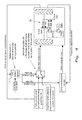
- a method 100 for determining if a shift is to be made is illustrated in Fig. 3 .
- a decision is made as to whether a shift is in progress, if the answer is "No", then it determines if transmission 80 of vehicle 10 is in one gear or another at steps 104 and 114. If transmission 80 is in the 1 st gear, then a further evaluation is made at step 106 as to whether the transmission output speed (TOS)/ Engine speed ratio is greater than a predetermined up-shift point, if so, and all other shift conditions are met at step 108, then an upshift is initiated at step 110.
- TOS transmission output speed
- Engine speed ratio is greater than a predetermined up-shift point, if so, and all other shift conditions are met at step 108, then an upshift is initiated at step 110.
- step 112 a shift is in progress then method 100 transitions to step 112 until the shift is complete, hence ignoring inputs, such as those from steps 106, 108, 116, and 118, as well as operator inputs until the shift has been completed.
- the present invention uses a combination of feed-forward and feedback control methods to achieve minimum transmission output speed interruption felt by the operator driving vehicle 10 while gear shifting progresses in electronically controlled 2-speed electronically controlled mechanical transmission 80.
- the displacements of pump 84 and motor 86 and the engagement-disengagement of gear clutches 88 and 90 are controlled by the transmission shift control logic in electronic control unit 96 based on various inputs, such as operator commands, measured torque going through the transmission, measured vehicle speed and/or acceleration, measured pressure between pump and motor in the hydraulic circuit, engine speed etc.
- a shift is commanded based on the value of the transmission output speed (TOS) to engine speed ratio.
- TOS transmission output speed
- the actuator associated with the oncoming clutch 88 or 90 is actuated until a (kiss) point occurs, in that the clutch starts transmitting torque without any further increase in current to the solenoid, which activates the actuator associated with that particular clutch.
- the increase-decrease rate, magnitude and crossover point of on-coming and off-going clutch current to the solenoids during shifts is determined based on the required output torque of transmission 80.
- pump and motor displacements are purely calculated based on vehicle velocity and/or acceleration feedback and engine speed independent of vehicle velocity or acceleration commands from the operator driving vehicle 10.
- the pump and motor displacements are increased or decreased during the shift using vehicle velocity and/or acceleration feedback in order to maintain the desired acceleration or deceleration and/or velocity of vehicle 10. Additionally, pump and motor commands compensate for a detected or anticipated increase in vehicle velocity during up-shift and conversely a decrease in vehicle velocity during down-shifts.
- the present invention advantageously incorporates a combined open and closed loop control method for controlling the shifting of a hydro-mechanical transmission, which has a variable displacement pump and a variable displacement motor in series with electronically controlled mechanical transmission of a vehicle.
- the control method includes controlling the clutches based on estimation or measurement of required transmission output torque and controlling the pump and/or motor displacements based on a difference of gear ratio associated with on-coming and off-going clutches, measured vehicle velocity and/ or acceleration feedback and engine speed during the up or down shift of the transmission.
Landscapes
- Engineering & Computer Science (AREA)
- General Engineering & Computer Science (AREA)
- Mechanical Engineering (AREA)
- Control Of Transmission Device (AREA)
Applications Claiming Priority (1)
| Application Number | Priority Date | Filing Date | Title |
|---|---|---|---|
| US14/298,606 US9303760B2 (en) | 2014-06-06 | 2014-06-06 | System and method of controlling shifts of an electronically controlled mechanical transmission of a vehicle |
Publications (1)
| Publication Number | Publication Date |
|---|---|
| EP2952783A1 true EP2952783A1 (de) | 2015-12-09 |
Family
ID=53793922
Family Applications (1)
| Application Number | Title | Priority Date | Filing Date |
|---|---|---|---|
| EP15170857.5A Withdrawn EP2952783A1 (de) | 2014-06-06 | 2015-06-05 | System und verfahren zur steuerung von schaltungen eines elektronisch gesteuerten mechanischen getriebes eines fahrzeugs |
Country Status (3)
| Country | Link |
|---|---|
| US (1) | US9303760B2 (de) |
| EP (1) | EP2952783A1 (de) |
| BR (1) | BR102015013292B1 (de) |
Families Citing this family (2)
| Publication number | Priority date | Publication date | Assignee | Title |
|---|---|---|---|---|
| DE102016200992A1 (de) * | 2016-01-25 | 2017-07-27 | Zf Friedrichshafen Ag | Getriebevorrichtung und Verfahren zum Betreiben der Getriebevorrichtung |
| KR102801665B1 (ko) * | 2019-04-09 | 2025-05-02 | 엘에스엠트론 주식회사 | 농업용 작업차량의 주행속도 제어장치 및 농업용 작업차량의 주행속도 제어방법 |
Citations (3)
| Publication number | Priority date | Publication date | Assignee | Title |
|---|---|---|---|---|
| EP0282010A2 (de) * | 1987-03-09 | 1988-09-14 | Hydromatik GmbH | Antriebseinrichtung, bestehend aus einem Antriebsmotor wechselnder Drehzahl, einem verstellbaren hydrostatischen Getriebe und einer schaltbaren Einrichtung |
| DE9318017U1 (de) * | 1993-11-25 | 1995-03-23 | O & K Orenstein & Koppel Ag, 13581 Berlin | Elektro-hydraulische Steuerung für lastschaltbare Getriebe in Fahrzeugen |
| DE4431864A1 (de) * | 1994-09-07 | 1996-03-14 | Zahnradfabrik Friedrichshafen | Fahrantrieb |
Family Cites Families (25)
| Publication number | Priority date | Publication date | Assignee | Title |
|---|---|---|---|---|
| US3969958A (en) * | 1973-03-28 | 1976-07-20 | Aisin Seiki Kabushiki Kaisha | Output split type hydrostatic transmission |
| DE2742031B2 (de) | 1977-09-19 | 1979-09-13 | Robert Bosch Gmbh, 7000 Stuttgart | Gangwechseleinrichtung für Fahrzeug-Lastschaltgetriebe |
| US4187739A (en) * | 1977-12-13 | 1980-02-12 | Zahnradfabrik Friedrichshafen Ag | Hydrostatic torque converter having a stepped transmission |
| US4766779A (en) * | 1984-03-05 | 1988-08-30 | Fabco Automotive Corporation | Hydrostatic transmission assembly and method of increasing the torque and speed range thereof |
| DE3667836D1 (de) * | 1986-02-24 | 1990-02-01 | Shimadzu Corp | Hydromechanisches getriebe. |
| DE3807599A1 (de) * | 1988-03-08 | 1989-09-28 | Hydromatik Gmbh | Automotive antriebseinrichtung fuer maschinen und fahrzeuge |
| JP3042848B2 (ja) | 1989-12-26 | 2000-05-22 | アイシン・エィ・ダブリュ株式会社 | 電子制御式自動変速機 |
| DE4109884A1 (de) * | 1991-03-26 | 1992-10-01 | Claas Ohg | Steuerung einer verdraengermaschine eines hydrostatisch-mechanischen lastschaltgetriebes |
| US5323667A (en) | 1992-10-02 | 1994-06-28 | Caterpillar Inc. | Integrated engine and transmission control system |
| IT1271804B (it) * | 1994-12-27 | 1997-06-09 | Clark Hurth Components Spa | Procedimento di controllo globale di un gruppo di trazione per un cambio mosso da un sistema idrostatico |
| US5848370A (en) | 1995-04-03 | 1998-12-08 | Nippondenso Co., Ltd. | Hydraulic pressure control apparatus for automatic transmission |
| KR970066220A (ko) | 1996-03-13 | 1997-10-13 | 가나이 쯔도무 | 자동 변속기의 제어 장치 및 제어 방법 |
| US6481314B2 (en) * | 2000-01-07 | 2002-11-19 | Kanzaki Kokyukoki Mfg. Co. Ltd. | Vehicle travelling control apparatus |
| US6272950B1 (en) * | 2000-01-28 | 2001-08-14 | Sauer-Danfoss Inc. | Drive train for a vehicle and method of controlling a drive train |
| US6332860B1 (en) | 2000-03-20 | 2001-12-25 | General Motors Corporation | Model-based on-coming clutch pressure control for an automatic transmission upshift |
| JP2001280465A (ja) * | 2000-03-31 | 2001-10-10 | Honda Motor Co Ltd | 無段変速機の制御方法 |
| JP3902379B2 (ja) * | 2000-03-31 | 2007-04-04 | 本田技研工業株式会社 | 変速機の制御方法 |
| US7300381B2 (en) | 2002-11-30 | 2007-11-27 | Ford Global Technologies, Llc | Method for managing engine torque during a gear shift in an automatic shift manual transmission |
| US7354368B2 (en) * | 2005-01-31 | 2008-04-08 | Sauer-Danfoss Inc. | Method and means for shifting a hydromechanical transmission |
| US7686737B2 (en) * | 2005-09-30 | 2010-03-30 | Kubota Corporation | Speed control structure and method for work vehicle |
| ITMI20052099A1 (it) | 2005-11-04 | 2007-05-05 | Laverda S P A | Trasmissi0ne meccanica-idrostatica a gesdtione elettronica per macchine operatrici e trattrioci agricole |
| WO2011068043A1 (ja) | 2009-12-04 | 2011-06-09 | 本田技研工業株式会社 | 自動変速機の制御装置 |
| US8337361B2 (en) | 2010-01-25 | 2012-12-25 | Ford Global Technologies, Llc | Multiple-ratio automatic transmission control method and system for ratio upshifts |
| US20120065854A1 (en) | 2010-09-10 | 2012-03-15 | Caterpillar Inc. | System and method to prevent shift hunting in a powertrain |
| WO2013028275A1 (en) * | 2011-08-25 | 2013-02-28 | Cnh America, Llc | Shuttle shifting for a continuously variable transmission |
-
2014
- 2014-06-06 US US14/298,606 patent/US9303760B2/en active Active
-
2015
- 2015-06-05 EP EP15170857.5A patent/EP2952783A1/de not_active Withdrawn
- 2015-06-08 BR BR102015013292-1A patent/BR102015013292B1/pt not_active IP Right Cessation
Patent Citations (3)
| Publication number | Priority date | Publication date | Assignee | Title |
|---|---|---|---|---|
| EP0282010A2 (de) * | 1987-03-09 | 1988-09-14 | Hydromatik GmbH | Antriebseinrichtung, bestehend aus einem Antriebsmotor wechselnder Drehzahl, einem verstellbaren hydrostatischen Getriebe und einer schaltbaren Einrichtung |
| DE9318017U1 (de) * | 1993-11-25 | 1995-03-23 | O & K Orenstein & Koppel Ag, 13581 Berlin | Elektro-hydraulische Steuerung für lastschaltbare Getriebe in Fahrzeugen |
| DE4431864A1 (de) * | 1994-09-07 | 1996-03-14 | Zahnradfabrik Friedrichshafen | Fahrantrieb |
Also Published As
| Publication number | Publication date |
|---|---|
| US9303760B2 (en) | 2016-04-05 |
| BR102015013292B1 (pt) | 2023-10-24 |
| BR102015013292A2 (pt) | 2016-06-21 |
| US20150354699A1 (en) | 2015-12-10 |
Similar Documents
| Publication | Publication Date | Title |
|---|---|---|
| US9462751B2 (en) | Method of remotely configuring a residue system of an agricultural harvester | |
| EP2127515B1 (de) | Kornreinigungsanordnung | |
| US20190124849A1 (en) | Residue Handling System for an Agricultural Harvester | |
| EP3597028B1 (de) | Gebläseantrieb in abhängigkeit von der last auf den reinigungsgebläseantrieb | |
| EP3148311B1 (de) | Reiningungsgruppe einer landwirtschaftlichen erntemaschine mit einem reinigungssiebneigungskompensationssystem | |
| EP3207787A1 (de) | System zur anpassung der rundhöhlung einer landwirtschaftlichen erntemaschine | |
| EP3542616B1 (de) | Mähdrescher mit gebläsegeschwindigkeitsanpassung | |
| EP2939906B1 (de) | Arbeitsfahrzeug mit hydraulischer unterstützung zum lenken im ausgeschalteten zustand | |
| US9303760B2 (en) | System and method of controlling shifts of an electronically controlled mechanical transmission of a vehicle | |
| EP2936966B1 (de) | Reinigungssystemantrieb mit variablem hub für eine landwirtschaftliche erntemaschine | |
| US9469290B2 (en) | Power/economy mode control system for an agricultural vehicle | |
| JP2009159885A (ja) | コンバイン | |
| EP1356721A1 (de) | Verfahren um eine Machinenanlage anzufahren | |
| JP2009106256A (ja) | 収穫機 | |
| EP3672390B1 (de) | Antriebssystem für eine landwirtschaftliche abtankvorrichtung | |
| JP2009112265A (ja) | 収穫機 | |
| US20240251710A1 (en) | Self-propelled engine overspeed control | |
| EP4578261A1 (de) | System und verfahren zur erkennung von rotorverbugung einer landwirtschaftlichen erntemaschine | |
| JP2017012037A (ja) | コンバイン |
Legal Events
| Date | Code | Title | Description |
|---|---|---|---|
| PUAI | Public reference made under article 153(3) epc to a published international application that has entered the european phase |
Free format text: ORIGINAL CODE: 0009012 |
|
| AK | Designated contracting states |
Kind code of ref document: A1 Designated state(s): AL AT BE BG CH CY CZ DE DK EE ES FI FR GB GR HR HU IE IS IT LI LT LU LV MC MK MT NL NO PL PT RO RS SE SI SK SM TR |
|
| AX | Request for extension of the european patent |
Extension state: BA ME |
|
| STAA | Information on the status of an ep patent application or granted ep patent |
Free format text: STATUS: THE APPLICATION HAS BEEN WITHDRAWN |
|
| 18W | Application withdrawn |
Effective date: 20160613 |