WO2011068043A1 - 自動変速機の制御装置 - Google Patents
自動変速機の制御装置 Download PDFInfo
- Publication number
- WO2011068043A1 WO2011068043A1 PCT/JP2010/070701 JP2010070701W WO2011068043A1 WO 2011068043 A1 WO2011068043 A1 WO 2011068043A1 JP 2010070701 W JP2010070701 W JP 2010070701W WO 2011068043 A1 WO2011068043 A1 WO 2011068043A1
- Authority
- WO
- WIPO (PCT)
- Prior art keywords
- value
- learning
- torque
- automatic transmission
- vehicle
- Prior art date
- Legal status (The legal status is an assumption and is not a legal conclusion. Google has not performed a legal analysis and makes no representation as to the accuracy of the status listed.)
- Ceased
Links
Images

















Classifications
-
- F—MECHANICAL ENGINEERING; LIGHTING; HEATING; WEAPONS; BLASTING
- F02—COMBUSTION ENGINES; HOT-GAS OR COMBUSTION-PRODUCT ENGINE PLANTS
- F02D—CONTROLLING COMBUSTION ENGINES
- F02D29/00—Controlling engines, such controlling being peculiar to the devices driven thereby, the devices being other than parts or accessories essential to engine operation, e.g. controlling of engines by signals external thereto
- F02D29/02—Controlling engines, such controlling being peculiar to the devices driven thereby, the devices being other than parts or accessories essential to engine operation, e.g. controlling of engines by signals external thereto peculiar to engines driving vehicles; peculiar to engines driving variable pitch propellers
-
- F—MECHANICAL ENGINEERING; LIGHTING; HEATING; WEAPONS; BLASTING
- F16—ENGINEERING ELEMENTS AND UNITS; GENERAL MEASURES FOR PRODUCING AND MAINTAINING EFFECTIVE FUNCTIONING OF MACHINES OR INSTALLATIONS; THERMAL INSULATION IN GENERAL
- F16H—GEARING
- F16H59/00—Control inputs to control units of change-speed- or reversing-gearings for conveying rotary motion
- F16H59/48—Inputs being a function of acceleration
-
- F—MECHANICAL ENGINEERING; LIGHTING; HEATING; WEAPONS; BLASTING
- F16—ENGINEERING ELEMENTS AND UNITS; GENERAL MEASURES FOR PRODUCING AND MAINTAINING EFFECTIVE FUNCTIONING OF MACHINES OR INSTALLATIONS; THERMAL INSULATION IN GENERAL
- F16H—GEARING
- F16H61/00—Control functions within control units of change-speed- or reversing-gearings for conveying rotary motion ; Control of exclusively fluid gearing, friction gearing, gearings with endless flexible members or other particular types of gearing
- F16H61/04—Smoothing ratio shift
- F16H61/06—Smoothing ratio shift by controlling rate of change of fluid pressure
- F16H61/061—Smoothing ratio shift by controlling rate of change of fluid pressure using electric control means
-
- F—MECHANICAL ENGINEERING; LIGHTING; HEATING; WEAPONS; BLASTING
- F16—ENGINEERING ELEMENTS AND UNITS; GENERAL MEASURES FOR PRODUCING AND MAINTAINING EFFECTIVE FUNCTIONING OF MACHINES OR INSTALLATIONS; THERMAL INSULATION IN GENERAL
- F16H—GEARING
- F16H63/00—Control outputs from the control unit to change-speed- or reversing-gearings for conveying rotary motion or to other devices than the final output mechanism
- F16H63/40—Control outputs from the control unit to change-speed- or reversing-gearings for conveying rotary motion or to other devices than the final output mechanism comprising signals other than signals for actuating the final output mechanisms
- F16H63/50—Signals to an engine or motor
- F16H63/502—Signals to an engine or motor for smoothing gear shifts
-
- F—MECHANICAL ENGINEERING; LIGHTING; HEATING; WEAPONS; BLASTING
- F16—ENGINEERING ELEMENTS AND UNITS; GENERAL MEASURES FOR PRODUCING AND MAINTAINING EFFECTIVE FUNCTIONING OF MACHINES OR INSTALLATIONS; THERMAL INSULATION IN GENERAL
- F16H—GEARING
- F16H61/00—Control functions within control units of change-speed- or reversing-gearings for conveying rotary motion ; Control of exclusively fluid gearing, friction gearing, gearings with endless flexible members or other particular types of gearing
- F16H2061/0075—Control functions within control units of change-speed- or reversing-gearings for conveying rotary motion ; Control of exclusively fluid gearing, friction gearing, gearings with endless flexible members or other particular types of gearing characterised by a particular control method
- F16H2061/0087—Adaptive control, e.g. the control parameters adapted by learning
Definitions
- the present invention relates to a control device for an automatic transmission, and more specifically to a device that estimates and evaluates vehicle acceleration at the time of shifting and learns variations in transmission torque of friction engagement elements.
- Patent Document 1 in a control device for an automatic transmission that includes a plurality of gears and hydraulic clutches (friction engagement elements) and that supplies and discharges hydraulic oil to and from the hydraulic clutch, There has been proposed a technique for improving the rise characteristic of pressure.
- the object of the present invention is to solve the above-mentioned problems, estimate and evaluate vehicle acceleration at the time of gear shifting, and then learn the variation of the transmission torque of the friction engagement element, etc., thereby sufficiently increasing the potential of the friction engagement element.
- An object of the present invention is to provide a control device for an automatic transmission which improves the drawing and shifting feeling.
- the automatic shift Input rotation speed detection means for detecting the input rotation speed of the machine
- output rotation speed detection means for detecting the output rotation speed of the automatic transmission
- output rotation speed change amount calculation means for calculating the change amount of the output rotation speed
- an output rotation speed change amount average value calculating means for calculating an average value of the change amount of the output rotation speed in a predetermined period at the initial stage of the inertia phase of the shift, and the end of the shift from the ratio of the input rotation speed and the output rotation speed.
- Vehicle acceleration average value calculating means for calculating an average value of the vehicle acceleration after the shift is completed from the amount of change in the output rotation speed on the assumption that the change amount in the output rotation speed indicates vehicle acceleration.
- the difference calculating means for calculating the difference between the average value of the change in the output rotational speed and the average value of the vehicle acceleration, and the target transmission torque of the friction engagement element so that the calculated difference falls within a predetermined range.
- Learning value calculation means for calculating a learning value for increasing / decreasing the value
- increase / decrease correcting means for increasing / decreasing a target value of the transmission torque of the friction engagement element with the calculated learning value, and the transmission torque corrected for increase / decrease
- a supply hydraulic pressure control means for controlling the hydraulic pressure supplied to the frictional engagement element so that the target value is obtained.
- the “increase / decrease correction means” may be configured to increase / decrease the hydraulic pressure to be supplied to the friction engagement element so that the calculated difference falls within a predetermined range instead of the transmission torque. That is, in the above, “transmission torque” is used in the same meaning as “supply hydraulic pressure”.
- the automatic transmission control apparatus further includes an engine torque down request amount for calculating a torque down request amount of the engine based on the target value of the transmission torque corrected for increase / decrease. Calculation means and engine torque reduction means for reducing the engine torque in accordance with the calculated torque-down request amount are provided.
- the engine torque down request amount calculation means calculates the engine torque down request amount when the shift time exceeds a target shift time by a predetermined value or more. It was constituted so as to calculate.
- the increase / decrease correction means has the calculated difference within a predetermined range when the traveling state of the vehicle is in a predetermined state. In this way, the target value of the transmission torque of the friction engagement element is corrected to increase or decrease.
- the input torque calculation means for calculating the input torque input to the automatic transmission, at least the input torque before and after the shift, and the output Vehicle weight estimation means for estimating the weight of the vehicle from the amount of change in the rotational speed, and learning value correction means for correcting the learning value with the estimated weight of the vehicle are provided.
- the learning value correcting means is configured to prohibit learning when the estimated weight of the vehicle exceeds a threshold value.
- the vehicle weight estimation means considers that the running resistance acting on the vehicle does not change during the shift, and before and after the shift.
- the weight of the vehicle is estimated from the input torque and the amount of change in the output rotational speed.
- control apparatus for an automatic transmission includes a calorific value calculation means for calculating a calorific value of the friction engagement element during the shift, and the calculated friction engagement.
- Second learning value correction means for correcting the learning value so as to correct and decrease at least the engine torque of the engine torque and the transmission torque when the amount of heat generated during shifting of the element exceeds a threshold value.
- an engine torque reducing means for reducing the torque of the engine so that the decrease corrected value is obtained.
- the second learning value correction means increases the transmission torque when the engine torque decrease correction amount exceeds a limit value. It was configured to correct.
- the second learning value correcting means generates the torque of the engine when the shift time exceeds a target shift time by a predetermined value or more. It was configured to correct for decrease.
- the learning value calculation means uses the learning basic value retrieved from the characteristics set for each grid point of a predetermined driving parameter as the driving.
- the learning value is calculated by correcting with a correction coefficient calculated from a value other than the lattice point of the parameter.
- the learning value calculation means is configured to calculate the correction coefficient based on a comparison result obtained by comparing the calculated difference with a threshold value. It was constituted so as to calculate.
- the learning value calculation means is configured to correct the correction coefficient with the temperature of the hydraulic oil.
- control apparatus for an automatic transmission includes driving elapsed time estimation means for estimating the driving elapsed time of the automatic transmission, and the learning value calculation means is the estimated value.
- the learning value is changed according to the elapsed driving time.
- the learning value calculation means is configured to prohibit the calculation of the learning value when it is determined that the vehicle is traveling on a rough road.
- the learning value calculation means calculates the difference between the average value of the changes in the output rotational speed and the average value of the vehicle acceleration. When the learning value exceeds an allowable range when the target value of the transmission torque of the friction engagement element is assumed to be increased or decreased, calculation of the learning value is prohibited.
- an average value of the amount of change in the output speed of the automatic transmission during a predetermined period at the initial stage of the inertia phase of the speed change is calculated, and the input speed of the automatic transmission is calculated.
- the end of the shift is determined from the ratio of the output speed, the amount of change in the output speed is regarded as indicating the vehicle acceleration, and then the average value of the vehicle acceleration after the shift is completed is calculated, and the change in the output speed.
- the difference between the average value of the quantity and the average value of the vehicle acceleration is calculated, and a learning value is calculated and corrected to increase or decrease the target value of the transmission torque of the friction engagement element so that the calculated difference falls within a predetermined range.
- the target value of the transmission torque of the friction engagement element is corrected to increase / decrease with the learned value, and the hydraulic pressure supplied to the friction engagement element is controlled so as to become the target value of the transmission torque corrected for increase / decrease, Estimate and evaluate vehicle acceleration Then becomes possible to learn the variations in the transmission torque of the frictional engagement elements, the potential of the frictional engagement element can be pulled out sufficiently and thus it is possible to improve the shift feeling which the occupant is subjected during shifting.
- the engine torque-down request amount is further calculated based on the target value of the transmission torque corrected for increase / decrease, and the engine torque-down request amount is calculated according to the calculated torque-down request amount. Since the torque is reduced, when the shift time is likely to be extended by performing the control described in claim 1, it is possible to converge the target shift time by reducing the engine torque. In addition, it is possible to suppress the deterioration of the shift feeling such as a feeling of extension during the shift, and it is possible to improve the durability by suppressing the increase in the heat generation amount of the friction engagement element.
- the control apparatus for an automatic transmission according to claim 3 is configured to calculate the engine torque-down request amount when the shift time exceeds the target shift time by a predetermined value or more. Therefore, the effect described in claim 2 is achieved. In addition, the shift time can be more reliably converged to the target shift time.
- the control device for an automatic transmission when the running state of the vehicle is in a predetermined state, the target value of the transmission torque of the friction engagement element so that the calculated difference falls within a predetermined range.
- the increase / decrease correction in other words, learning can be limited to the predetermined traveling state of the effect, and the configuration can be simplified.
- the input torque input to the automatic transmission is calculated, and the weight of the vehicle is estimated from at least the input torque before and after the shift and the amount of change in the output rotational speed. Since the learning value is corrected by the estimated vehicle weight, in addition to the effects described above, the learning value is prevented from being incorrect due to the vehicle acceleration being influenced by the vehicle weight. The value can be converged stably. Further, the same type of parameter as the calculation of the transmission torque of the friction engagement element is used for estimating the weight of the vehicle, and the weight of the vehicle can be easily estimated.
- the weight of the vehicle is determined based on the input torque before and after the shift and the amount of change in the output rotational speed, assuming that the running resistance acting on the vehicle does not change during the shift.
- the weight of the vehicle can be estimated without being affected by the running resistance or the gradient of the running road.
- the automatic transmission control device when the heat generation amount during the shift of the friction engagement element is calculated, and the calculated heat generation amount during the shift of the friction engagement element exceeds a threshold value Since the learning value is corrected so that at least the engine torque of the engine torque and the transmission torque is corrected to decrease, and the engine torque is decreased so as to be the corrected value, the above-described effect is achieved. In addition, the durability of the hydraulic clutch Cn can be improved.
- the engine torque is decreased and corrected when the shift time exceeds the target shift time by a predetermined value or more.
- the shift time is likely to be extended by performing transmission torque variation absorption control due to the vehicle acceleration, it is possible to converge to the target shift time by reducing the engine torque.
- the learning basic value retrieved from the characteristics set for each grid point of the predetermined operation parameter is corrected from a value other than the grid point of the operation parameter. Since the learning value is calculated by correcting with a coefficient, in addition to the above-described effects, even when the operation parameter takes a value other than the grid point, the difference from the learning value calculated when the grid point is taken Therefore, the speed change feeling can be optimized in a short time.
- the correction coefficient is calculated based on the comparison result obtained by comparing the calculated difference with the threshold value.
- the threshold value By appropriately setting the threshold value, the calculated difference can be surely put in a predetermined range.
- the correction coefficient is corrected by the temperature of the hydraulic oil.
- the learning value can be obtained by considering the oil temperature of the hydraulic oil. Can be calculated more appropriately.
- the automatic transmission control device is configured to estimate the elapsed driving time of the automatic transmission and change the learning value in accordance with the estimated elapsed driving time.
- the correction amount can be increased, while when it is long, the correction amount can be decreased so as to reduce the correction amount. Learning can be appropriately performed according to individual differences due to initial variation or aging deterioration, in other words, variations can be effectively absorbed.
- control device for an automatic transmission it is determined whether or not the vehicle is traveling on a rough road by comparing the amount of change in the output speed of the automatic transmission with a threshold value.
- the calculation of the learning value is prohibited, so that erroneous learning can be prevented in addition to the above-described effects.
- the target value of the transfer torque of the frictional engagement element is a learning value obtained by calculating a difference between the average value of the change amount of the output rotation speed and the average value of the vehicle acceleration.
- the difference between the current value of the evaluation value and the past value is not limited to the above effect.
- FIG. 1 is a schematic diagram showing an entire automatic transmission control apparatus according to a first embodiment of the present invention. It is a flowchart which shows operation
- movement of the control apparatus of the automatic transmission shown in FIG. 2 is a sub-routine flow chart showing the learning value reading process of the flow chart.
- FIG. 3 is a sub-routine flowchart showing a target clutch torque calculation process in the flowchart of FIG. 2.
- 2 is a waveform diagram showing the G waveform and the ⁇ NC estimated value described in the flow chart and the like. It is a wave form diagram which shows (DELTA) NC estimated value etc. in gear shifting.
- 3 is a sub-routine flow chart showing the G waveform learning process of the flow chart.
- FIG. 1 is a schematic diagram showing an entire automatic transmission control apparatus according to a first embodiment of the present invention. It is a flowchart which shows operation
- movement of the control apparatus of the automatic transmission shown in FIG. 2 is a sub-routine flow chart showing the learning value reading process of the flow chart
- FIG. 8 is a sub-routine flowchart showing a G waveform evaluation permission determination process of the flowchart of FIG. 7.
- FIG. 7 is a sub-routine flow chart showing a learning value writing process of the flow chart.
- 9 is a sub-routine flow chart showing a learning ⁇ torque (learning value) subtraction process of the flow chart. 7 is an explanatory diagram showing the characteristics of a learning ⁇ torque map used in the learning value writing process of the flow chart.
- FIG. 9 is a sub-routine flow chart showing learning ⁇ torque (learning value) addition processing of the flow chart.
- FIG. 6 is a flowchart similar to FIG. 2 showing the operation of the control device for the automatic transmission according to the second embodiment of the present invention.
- FIG. 13 is a sub-routine flowchart showing the learning value reading process of the flowchart.
- FIG. 14 is a sub-routine flowchart showing a calculation process of a torque-down request amount in the flowchart of FIG. 13.
- FIG. 14 is a sub-routine flow chart illustrating a learned value writing process of the torque-down request amount in the flowchart of FIG. 13.
- FIG. 16 is a sub-routine flow chart showing a calculation process of a learning ⁇ request amount in the flow chart. 14 is a time chart showing a comparison between the process of the first embodiment shown in the flow chart of FIG. 2 and the second embodiment shown in the flow chart of FIG.
- FIG. 20 is a sub-routine flow chart showing a vehicle weight estimation process in the flowchart of FIG. It is explanatory drawing explaining the weight estimation process of the vehicle of the FIG. 20 flowchart.
- FIG. 21 is a sub-routine flowchart showing a vehicle weight (vehicle inertia) estimated value calculation process in the flowchart of FIG. 20.
- FIG. 20 is a sub-routine flowchart showing the learning value writing process of the flowchart of FIG. 19.
- FIG. 23 is a sub-routine flowchart showing the learning permission determination process of the flowchart.
- FIG. 20 is a sub-routine flow chart showing a vehicle weight estimation process in the flowchart of FIG. It is explanatory drawing explaining the weight estimation process of the vehicle of the FIG. 20 flowchart.
- FIG. 21 is a sub-routine flowchart showing a vehicle weight (vehicle inertia) estimated value calculation process in the flowchart of FIG. 20.
- FIG. 20
- FIG. 23 is a sub-routine flowchart showing learning ⁇ torque calculation / writing processing of the flowchart. It is a sub routine flow chart which shows operation
- FIG. 26 is a sub-routine flow chart showing a learning value reading process of the flow chart. It is explanatory drawing explaining the calculation processing of target values, such as the target clutch torque of the FIG. 26 flowchart.
- FIG. 27 is a sub-routine flowchart showing a Q / A (heat generation amount) learning process of the flowchart of FIG. 26.
- FIG. 29 is an explanatory diagram illustrating a Q / A (heat generation amount) calculation process of the flowchart.
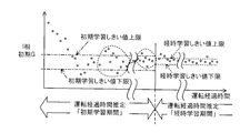
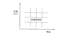
- FIG. 33 is an explanatory diagram showing characteristics of a learning value map used in the fifth embodiment described in FIG. 32 (used in the same processing as the learning value writing processing in the flowchart of FIG. 7 of the first embodiment). . It is a time chart shown in contrast with the case where the case where the process demonstrated in FIG. 32 is performed is different. It is a sub routine flow chart which shows the operation
- FIG. 35 is an explanatory diagram showing characteristics of threshold values used in the flow chart.
- FIG. 35 is a sub-routine flowchart showing the initial learning ⁇ torque subtraction process of the flowchart.
- FIG. 37 is an explanatory diagram showing characteristics of an initial learning ⁇ torque map searched by the flowchart.
- FIG. 35 is a sub-routine flowchart showing initial learning ⁇ torque addition processing of the flowchart.
- FIG. 35 is a sub-routine flow chart showing a time-dependent learning ⁇ torque subtraction process of the flow chart.
- FIG. 40 is an explanatory diagram showing characteristics of a time-learning ⁇ torque map searched by the flow chart.
- FIG. 40 is an explanatory diagram showing characteristics of a time-learning ⁇ torque map searched by the flow chart.
- FIG. 35 is a sub-routine flow chart showing a time-dependent learning ⁇ torque addition process of the flow chart.
- FIG. 35 is a time chart for explaining learning correction of the flow chart. It is a flowchart which shows operation
- FIG. 45 is a sub-routine flow chart showing rough road running determination processing of the flow chart of FIG. 44.
- FIG. 45 is an explanatory diagram illustrating processing of the flowchart. It is a sub routine flow chart which shows the learning value writing process of 7th Example. 47 is an explanatory diagram illustrating processing of the flow chart.
- FIG. 45 is a sub-routine flow chart showing rough road running determination processing of the flow chart of FIG. 44.
- FIG. 1 is a schematic diagram showing the overall control apparatus for an automatic transmission according to the first embodiment of the present invention.
- the symbol T indicates an automatic transmission (hereinafter referred to as “transmission”).
- the transmission T is mounted on a vehicle (not shown) and is a parallel shaft stepped type having speed stages of 5 forward speeds and 1 reverse speed.
- the transmission T includes a main shaft (input shaft) MS connected to an output shaft 10 connected to a crankshaft of an engine (internal combustion engine) E via a torque converter 12 having a lockup mechanism L, and the main shaft MS. And a counter shaft (output shaft) CS connected via a plurality of gear trains.
- the engine E includes a plurality of cylinders and a spark ignition engine using gasoline as fuel.
- the main first speed gear 14, the main second speed gear 16, the main third speed gear 18, the main fourth speed gear 20, the main fifth speed gear 22, and the main reverse gear 24 are supported on the main shaft MS.
- the counter shaft CS has a counter first speed gear 28 meshing with the main first speed gear 14, a counter second speed gear 30 meshing with the main second speed gear 16, a counter third speed gear 32 meshing with the main third speed gear 18,
- the counter 4th gear 34 meshed with the main 4th gear 20, the counter 5th gear 36 meshed with the main 5th gear 22, and the counter reverse gear 42 connected to the main reverse gear 24 via the reverse idle gear 40 are supported. Is done.
- the second gear (gear, speed stage) is established when the main second gear 16 supported on the main shaft MS so as to be relatively rotatable is coupled to the main shaft MS by the second-speed hydraulic clutch C2.
- the counter third-speed gear 32 that is rotatably supported on the countershaft CS is coupled to the countershaft CS by the third-speed hydraulic clutch C3, the third speed (gear, speed stage) is established.
- the main fourth speed gear 20 supported relatively rotatable on the main shaft MS is changed to the fourth speed-reverse.
- the hydraulic clutch C4R is coupled to the main shaft MS, the fourth speed (gear, speed stage) is established.
- the rotation of the counter shaft CS is transmitted to the differential D through a final drive gear 46 and a final driven gear 48, and then a vehicle (not shown) on which the engine E and the transmission T are mounted via the left and right drive shafts 50, 50. Are transmitted to the drive wheels W, W.
- a shift lever 54 is provided near the floor of the vehicle driver's seat (not shown), and one of eight ranges, P, R, N, D5, D4, D3, 2, 1 is selected by the driver's operation.
- a throttle valve (not shown) disposed in the intake passage (not shown) of the engine E is connected to a DBW (Drive By Wire) mechanism 55. That is, the throttle valve is mechanically disconnected from an accelerator pedal (not shown) and driven by an actuator (not shown) such as an electric motor.
- DBW Drive By Wire
- a throttle opening sensor 56 is provided near the actuator of the DBW mechanism 55, and outputs a signal indicating the throttle opening TH through the rotation amount of the actuator.
- a vehicle speed sensor 58 is provided in the vicinity of the final driven gear 48 and outputs a signal indicating the vehicle speed V every time the final driven gear 48 makes one rotation.
- a crank angle sensor 60 is provided in the vicinity of the camshaft (not shown), and a CYL signal is subdivided at a predetermined crank angle of a specific cylinder, a TDC signal is subdivided at a predetermined crank angle of each cylinder, and a crank obtained by subdividing the predetermined crank angle.
- a CRK signal is output for each angle (for example, 15 degrees).
- an absolute pressure sensor 62 is provided downstream of the throttle valve arrangement position of the intake passage of the engine E, and outputs a signal indicating the intake pipe absolute pressure (engine load) PBA.
- a first rotation speed sensor 64 is provided in the vicinity of the main shaft MS and outputs a signal indicating the rotation speed (input rotation speed of the transmission T) NM of the main shaft MS, and in the vicinity of the counter shaft CS.
- a second rotational speed sensor 66 is provided, and outputs a signal indicating the rotational speed of the countershaft CS (output rotational speed of the transmission T) NC.
- a shift lever position sensor 68 is provided in the vicinity of the shift lever 54 mounted in the vicinity of the vehicle driver's seat, and outputs a signal indicating the position selected by the driver among the eight positions (ranges) described above. To do.
- a temperature sensor 70 is provided in the vicinity of the reservoir of the hydraulic circuit O of the transmission T to output a signal proportional to the oil temperature (the temperature of the hydraulic oil Automatic Transmission Fluid) TATF and the oil passage connected to each clutch.
- TATF the temperature of the hydraulic oil Automatic Transmission Fluid
- a hydraulic switch 72 which outputs an ON signal when the hydraulic pressure supplied to each clutch reaches a predetermined value.
- a brake switch 74 is provided in the vicinity of a brake pedal (not shown) in the vehicle driver's seat, and outputs an ON signal in response to the driver's brake pedal operation, and in the vicinity of an accelerator pedal (not shown).
- An accelerator opening sensor 76 is provided to generate an output corresponding to the driver's accelerator opening (accelerator pedal depression amount) AP.
- the outputs of these sensors 56 and the like are sent to an ECU (Electronic Control Unit) 80.
- ECU Electronic Control Unit
- the ECU 80 includes a microcomputer including a CPU 82, a ROM 84, a RAM 86, an input circuit 88, and an output circuit 90.
- the microcomputer includes an A / D converter 92.
- the output of the sensor 56 and the like is input into the ECU 80 via the input circuit 88, the analog output is converted into a digital value via the A / D converter 92, and the digital output is processed by a waveform shaping circuit or the like. It is processed through a circuit (not shown) and stored in the RAM 86.
- the time interval between the output of the vehicle speed sensor 58 and the output of the CRK signal of the crank angle sensor 60 is measured by a counter (not shown), and the vehicle speed V and the engine speed NE are detected. Outputs of the first rotation speed sensor 64 and the second rotation speed sensor 66 are also counted, and an input rotation speed NM and an output rotation speed NC of the transmission are detected.
- the CPU 82 determines a destination stage or a target stage (gear ratio), and excites / de-energizes shift solenoids SL1 to SL5 arranged in the hydraulic circuit O via an output circuit 90 and a voltage supply circuit (not shown).
- the clutch oil passage switching control is performed, and the linear solenoids SL6 to SL8 are excited and de-energized to control the hydraulic pressure supplied to the hydraulic clutch Cn and the lockup mechanism L of the torque converter 12 related to the shift.
- the CPU 82 determines the fuel injection amount and ignition timing of the engine E, supplies the determined injection amount of fuel via an injector (not shown), and is determined via an ignition device (not shown). The fuel / intake mixture is ignited according to the ignition timing.
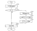
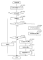
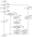
- FIG. 2 is a flowchart showing the processing.
- the illustrated program is executed by the CPU 82 every predetermined time.
- the ⁇ NC estimated value is calculated in S10.
- the estimated ⁇ NC value is the current NC (in the program loop) (the rotational speed of the countershaft CS detected by the second rotational speed sensor 66 (the output rotational speed of the transmission T, in other words, the vehicle speed V)) and the previous time. It means the difference obtained by subtracting NC (during program loop).
- the ⁇ NC estimated value is calculated for a waveform obtained by filtering the output of the second rotational speed sensor 66 with a low-pass filter to remove high frequency noise.
- FIG. 3 is a sub-routine flow chart showing the processing.
- a learning ⁇ torque map is searched to obtain a learning ⁇ torque (learned value.
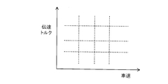
- the learning ⁇ torque is calculated for each speed stage and stored in the RAM 86 as a map value. That is, a learning ⁇ torque is calculated as a learning value in a learning value writing process, which will be described later, and is stored in the learning ⁇ torque map so that it can be searched for each grid point consisting of the transmission torque and the vehicle speed.
- a map corresponding to the speed stage of the speed change destination is selected from them, and a learning ⁇ torque is searched (read out) from the transmission torque of the hydraulic clutch Cn and the vehicle speed V.
- the transmission torque of the hydraulic clutch Cn is calculated from the engine speed NE of the engine E, the load (for example, the intake pipe absolute pressure PBA), and the slip ratio ETR of the torque converter 12.
- FIG. 4 is a sub-routine flow chart showing the processing.
- the target clutch torque is calculated as the target I (inertia) phase clutch torque.
- the target I-phase clutch torque is calculated by adding the learning ⁇ torque read in S14 to the transmission torque of the above-mentioned speed stage hydraulic clutch Cn.
- the value calculated in S200 is set as the target clutch torque in S16.
- G means vehicle acceleration, more precisely vehicle longitudinal acceleration
- G waveform means a vehicle acceleration waveform
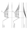
- FIG. 5 is a waveform diagram showing the G waveform and the above-described ⁇ NC estimated value and the like
- FIG. 6 is also a waveform diagram showing the ⁇ NC estimated value and the like in shifting.
- the estimated ⁇ NC value is regarded as indicating the vehicle acceleration G, and as shown in FIG. The vehicle acceleration at the time was estimated and evaluated, and then the transmission torque variation of the friction engagement element was learned.
- FIG. 7 is a sub-routine flow chart showing the G waveform learning process of the flow chart of FIG.
- G waveform evaluation permission judgment is performed in S300.
- FIG. 8 is a sub-routine flow chart showing the processing.
- the program proceeds to S412 to execute a change determination of the accelerator pedal opening AP. This is done by comparing the accelerator opening AP detected from the accelerator opening sensor 76 with an appropriate threshold value and determining whether or not the threshold value is exceeded.
- the process proceeds to S302, where it is determined whether the G waveform evaluation is permitted based on the bits of the permission flag. If the determination is affirmative, the process proceeds to S304, where it is determined whether the shift is an UP shift.
- the initial average G of the I phase following the T phase after the time of detection of the pull-in point is calculated from the ⁇ NC estimated value.
- the “initial” of the I phase is a section detected from GRATIO, which is disengaged from the hydraulic clutch Cn for the speed stage before the shift and is engaged with the hydraulic clutch Cn for the speed stage of the shift destination. It means a section in which engagement has progressed to a predetermined state since the start of the match.
- GRATIO indicates the ratio of the input rotation speed NM and the output rotation speed NC of the transmission T, that is, NC / NM, and indicates the shift state.
- the I-phase initial average G in S308 is calculated by determining that the ⁇ NC estimated value indicates the vehicle acceleration G and obtaining the ⁇ NC estimated value indicated by a circle A in FIG. 6 as the I-phase initial average G. More specifically, the I-phase initial average G is calculated by dividing the integrated value of the ⁇ NC estimated value in the above-described interval by the number of integrations.
- the average G after the shift is also determined from the GRATIO indicating the ratio of the input rotation speed NM and NC of the transmission T, and the ⁇ NC estimated value indicates the vehicle acceleration G. Calculation is performed by obtaining an average value in the same manner as the phase initial average G.
- FIG. 9 is a sub-routine flowchart showing the learning value writing process in S316.
- the upshift is from 1st to 2nd or 2nd to 3rd, learning is permitted when the vehicle speed is at a predetermined low vehicle speed, whether or not the vehicle is in such a running state. to decide.
- the reason why the upshift is limited to the above is that in order to realize a high-quality shift, it is impossible to properly learn unless otherwise.
- the process proceeds to S502, where it is determined whether learning is permitted based on the determination in S500. If the determination is affirmative, the process proceeds to S504, where the I-phase initial G is compared with the upper limit of the threshold (convergence threshold).
- FIG. 10 is a sub-routine flow chart showing the processing.
- the previous value of the learning ⁇ torque is searched. This is done by selecting a learning ⁇ torque map corresponding to the speed stage of the gear shift destination and then searching for the previous value of the learning ⁇ torque (the value at the previous execution of the flow chart in FIG. 3).
- FIG. 11 is an explanatory diagram showing the characteristics of the map.
- Such a map is prepared in the RAM 86 for each speed stage. Since the processing of S14 in the flowchart of FIG. 3 described above is performed by reading the value (learning ⁇ torque) written in this map, the pre-processing of writing is a map corresponding to the speed stage of the shift destination. Do by selecting.
- the subtraction amount per learning is calculated. Learning is for correcting individual differences due to variations in the hydraulic clutch Cn, and the dimensional tolerance of the hydraulic clutch Cn is set to have a large margin at the time of shipment from the factory so as not to cause engine blow-up and insufficient torque during shifting.
- the subtraction amount (or addition amount described later) per learning is obtained by dividing the dimensional tolerance by the target number of convergence.
- the initial learning ⁇ torque current value (value at the time of execution in the flowchart of FIG. 3) is calculated by adding the subtraction amount per time to the previous value. Since this is a subtraction process, the current value, the previous value, and the subtraction amount per time are all calculated as negative values.
- the transmission torque of the hydraulic clutch Cn is calculated at the same time, the vehicle speed V is detected, and the calculated current value is applied to the corresponding region of the grid point defined by the acquired transmission torque and the vehicle speed. Written (stored).
- FIG. 12 is a sub-routine flow chart showing the processing.
- the learning ⁇ torque map corresponding to the speed stage of the speed change destination is selected to search the previous value of the learning ⁇ torque, and the process proceeds to S702, and the addition amount per learning is calculated by the same method as in the subtraction process. calculate.
- the initial learning ⁇ torque current value is calculated by adding the addition amount per time to the previous value.
- the current value, the previous value, and the addition amount per time are all calculated as positive values.
- the transmission torque is calculated, the vehicle speed V is detected, and the calculated current value is written (stored) in the corresponding area of the grid point defined by the obtained transmission torque and the vehicle speed V.
- the learning count is increased (up). That is, the number of times the learning ⁇ torque is calculated in S506 or S512 is counted, and the counted number can be searched from the transmission torque of the hydraulic clutch Cn and the vehicle speed in a map prepared for each speed stage in the RAM 86. To store.
- the learning value calculated in the process of the flowchart of FIG. 9 is read in S14 of the flowchart of FIG. 2, the target clutch torque is calculated in S16 from the value, and the target clutch torque calculated in S18.
- the operation of the linear solenoid SLn is controlled so that
- the calculated difference (I-phase initial G) as shown in FIG.
- the target value (clutch torque command value) of the transmission torque of the friction engagement element is corrected so as to fall within a predetermined range, and the friction engagement element (hydraulic clutch Cn is adjusted so as to become the target value of the transmission torque corrected for increase / decrease )
- the vehicle acceleration G (and ⁇ NC estimated value) of the inertia (I) phase at the time of shifting can be reduced as indicated by an arrow in FIG.
- the vehicle acceleration G at the time of shifting is estimated and evaluated from the ⁇ NC estimated value, and then the variation in the transmission torque of the friction engagement element is learned, so that the potential of the friction engagement element can be fully extracted. Therefore, it is possible to improve the shifting feeling that the occupant receives during shifting.
- FIG. 13 is a flow chart similar to FIG. 2 showing the operation of the automatic transmission control apparatus according to the second embodiment of the present invention, and FIGS. 14 to 17 are sub-routine flow charts thereof.
- FIG. 18A is a time chart showing the process of the first embodiment
- FIG. 18B is a time chart showing the process of the second embodiment.
- the vehicle body G waveform can be flattened as shown at the end of FIG. 6A, thereby improving the shift feeling received by the occupant during shifting.
- the shift time is extended, which may deteriorate the shift feeling such as a feeling of extension during the shift.
- the ⁇ NC estimated value is calculated in S800, the process proceeds to S802, it is determined whether or not it is an UP (up) shift, and if affirmative, S804 is obtained. Proceed to and read the learning value.
- FIG. 14 is a sub-routine flow chart showing the processing, and a learning ⁇ request amount (described later) is read in S900.
- FIG. 15 is a sub-routine flow chart showing the processing.
- the base torque down request amount is searched in S1000, and the learned ⁇ request amount read in S804 is added to the torque reduction request amount. .
- the process proceeds to S808, where the torque of the engine E is reduced according to the calculated torque-down request amount. Specifically, this is performed by retarding the ignition timing by an amount corresponding to the calculated torque reduction request amount or by closing the throttle valve in the DBW mechanism 55.
- FIG. 16 is a sub-routine flow chart showing the processing.
- the subsequent processing is skipped.
- the process proceeds to S1102, and the target shift time is calculated by subtracting the target shift time from the current shift time.
- the target shift time is a fixed value set in advance.
- S1104 it is determined whether or not the calculated target time deviation exceeds a convergence threshold value.
- the convergence threshold is also a fixed value set in advance.
- the subsequent processing is skipped.
- the process proceeds to S1106, and the learning ⁇ request amount is calculated (calculated and written).
- FIG. 17 is a sub-routine flow chart showing the processing.
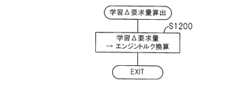
- the learning ⁇ request amount is calculated in S1200. That is, subtraction (decrease) of the target value of the transmission torque by learning of the shift speed gear hydraulic clutch Cn calculated by the processing of the second embodiment similar to S506 to S514 of the first embodiment, particularly S506 to S508.
- the correction amount (learning ⁇ torque current value) is read out and converted into the torque of the engine E to calculate the learning ⁇ request amount.
- the same map as shown in FIG. 11 is written in a searchable manner from the hydraulic clutch Cn and the vehicle speed V.
- the process proceeds to S1108, where a lower limit process is performed, and the process proceeds to S1110.
- the number of learning is counted in the same manner as in the first embodiment, and the counted number of times is Stored in a searchable manner from the transmission torque of Cn and the vehicle speed V. Since the remaining configuration of the second embodiment is not different from that of the first embodiment, the illustration is omitted.
- the second embodiment is configured as described above, when the shift time is likely to be extended by performing the control described in the first embodiment, the engine torque can be reduced to converge to the target shift time. It becomes possible, and deterioration of the shift feeling such as a feeling of extension during shift can be suppressed.
- the engine torque reduction request amount is calculated when the shift time exceeds the target shift time by a predetermined value or more, the shift time can be more reliably converged to the target shift time.
- the remaining configuration is not different from the first embodiment.
- the control device for the automatic transmission (transmission) T that changes the output of the engine E mounted on the vehicle via the friction engagement element (hydraulic clutch Cn) ( ECU 80), input rotational speed detection means (first rotational speed sensor 64, ECU 80) for detecting the input rotational speed NM of the automatic transmission, and output rotational speed detection for detecting the output rotational speed NC of the automatic transmission.
- Second rotational speed sensor 66, ECU 80 output rotational speed change amount calculating means (S10, S800) for calculating the output rotational speed change amount ( ⁇ NC estimated value), and shift inertia (I) phase Output rotation speed change amount average value calculating means (S20, S308, S810) for calculating an average value (I-phase initial average G) of the change amount of the output rotation speed in an initial predetermined period, and the input rotation From the ratio of NM and output rotational speed NC (GRATIO), the end of the shift is determined, and the change amount of the output rotational speed ( ⁇ NC estimated value) is regarded as indicating the vehicle acceleration G, and the change amount of the output rotational speed is determined.
- Second rotational speed sensor 66, ECU 80 output rotational speed change amount calculating means (S10, S800) for calculating the output rotational speed change amount ( ⁇ NC estimated value), and shift inertia (I) phase Output rotation speed change amount average value calculating means (S20, S308, S810) for calculating
- Vehicle acceleration average value calculating means (S20, S312, S810) for calculating an average value of vehicle acceleration after shifting is completed (average after shifting G), an average value of the change amount of the output rotation speed, and the vehicle acceleration Difference calculation means (S20, S314, S810) for calculating the difference between the average values of the two (S), S314, S810, and the target value of the transmission torque of the friction engagement element so that the calculated difference falls within a predetermined range
- Learning value calculation means S20, S316, S500 to S516, S810, S1100 to S1110) for calculating a learning value for increasing / decreasing correction, and transmission of the friction engagement element with the calculated learning value
- Increase / decrease correction means (S14 to S16) for correcting the target value of the torque
- supply hydraulic pressure control means (S18) for controlling the hydraulic pressure supplied to the friction engagement element so as to become the target value of the transmission torque corrected for increase / decrease
- the vehicle acceleration G at the time of shifting is estimated and evaluated from the ⁇ NC estimated value,
- the hydraulic pressure supplied to the friction engagement element is controlled so as to be the target value of the torque
- the vehicle acceleration G at the time of shifting is estimated and evaluated from the ⁇ NC estimated value, and then the variation in the transmission torque of the friction engagement element
- the potential of the frictional engagement element can be sufficiently extracted, and thus the shift feeling received by the occupant during the shift can be improved.
- the “increase / decrease correction unit” may be configured to increase / decrease the hydraulic pressure to be supplied to the friction engagement element so that the calculated difference falls within a predetermined range instead of the transmission torque. That is, in the above, “transmission torque” is used in the same meaning as “supply hydraulic pressure”.
- an engine torque down request amount calculation means (S812, S1100 to S1110, S804) that calculates a torque down request amount of the engine E based on the target value of the transmission torque corrected for increase / decrease.
- the gear shift is achieved by performing the control described in the first embodiment.
- the engine torque reduction request amount calculation means calculates the engine torque reduction request amount when the shift time exceeds the target shift time by a predetermined value (convergence threshold) or more. Since (S1102, 1104) is configured, the shift time can be more reliably converged to the target shift time.
- the increase / decrease correction means is configured to adjust the friction engagement element so that the calculated difference falls within a predetermined range when the running state of the vehicle is in a predetermined state. Since the target value of the transmission torque is corrected to increase / decrease (S20, S316, S500 to S514, S810), in addition to the above-described effect, the increase / decrease correction, in other words, learning is limited to a predetermined traveling state of the effect. And the configuration can be simplified.
- control apparatus for an automatic transmission according to the third embodiment of the present invention, more specifically, the operation thereof will be described.
- the weight of the vehicle is estimated, and the learning value is corrected by the estimated weight of the vehicle.
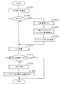
- FIG. 19 is a sub-routine flowchart showing the G waveform learning process of the third embodiment in the same process as the flowchart of FIG. 2 of the first embodiment.
- FIG. 20 is a sub-routine flow chart showing the processing.
- the input torque Tin input from the engine E to the transmission T is calculated in S1400.
- the torque transmission equation of the vehicle can be expressed as shown in FIG. A subscript consisting of 1 is added to the value before shifting, and 2 is added to the value after shifting.
- ⁇ NC estimated value is indicated as “ ⁇ NC1” or the like.
- the travel resistance can be regarded as constant, and as shown at the end of FIG.
- the vehicle weight can be estimated from the change amount and the ⁇ NC ( ⁇ NC estimated value) change amount.
- FIG. 22 is a sub-routine flow chart showing the processing.
- the vehicle inertia estimated value is calculated according to the equation shown in the figure.
- the formula shown is a modification of the formula shown at the end of FIG.
- the vehicle inertia estimated value is calculated as a converted value on the countershaft CS.
- the vehicle inertia estimated value is divided by the square of the moving radius of the drive wheel (tire) W, and the obtained quotient is divided by the speed reduction ratio corresponding to the final ratio (final speed reduction ratio). Is calculated (estimated vehicle weight).
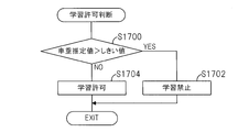
- FIG. 23 is a sub-routine flowchart showing the learning value writing process.
- FIG. 24 is a sub-routine flow chart showing the processing.
- the process proceeds to S1602, where it is determined whether learning is permitted based on the determination in S1600. If the determination is affirmative, the process proceeds to S1604, where the learning ⁇ torque is calculated and written.
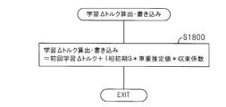
- FIG. 25 is a sub-routine flow chart showing the processing.
- step S1800 the learning ⁇ torque is calculated according to the equation shown in the figure. That is, the learning ⁇ torque (current) is calculated by adding the product obtained by multiplying the previous learning ⁇ torque by the initial I-phase G calculated in S1314 and the vehicle weight estimation value calculated in S1502 and the convergence coefficient. . In other words, the learning value is corrected by the estimated vehicle weight.
- the convergence coefficient described above integrates so that the variation in output and evaluation is reduced and learning converges stably, and sudden changes in gearing feeling due to learning are prevented, so that the driver does not feel uncomfortable during the convergence process. It is set appropriately using control.
- the calculated learning ⁇ torque is retrievably written in the learning ⁇ torque map stored in the RAM 86 as shown in FIG. 11 for each speed stage of the shift destination from the transmission torque of the hydraulic clutch Cn and the vehicle speed. (Stored).
- the process proceeds to S1606, ⁇ torque limit processing is performed, and the process proceeds to S1608.
- the number of times the learning ⁇ torque is calculated is counted, and the counted number is stored in the RAM 86.
- the map is retrievably written (stored) in the RAM 86 from the transmission torque and the vehicle speed of the hydraulic clutch Cn for the speed stage of the speed change destination. Since the remaining configuration of the third embodiment is not different from that of the first embodiment, the illustration is omitted.
- the input rotational speed detecting means (first rotational speed sensor 64, ECU 80) for detecting the input rotational speed NM of the automatic transmission and the output rotational speed detecting means for detecting the output rotational speed NC of the automatic transmission Second rotational speed sensor 66, ECU 80), output rotational speed change amount calculating means (S10) for calculating the output rotational speed change amount ( ⁇ NC estimated value), and a predetermined period at the initial stage of the inertia (I) phase of the shift
- the end of the shift is determined from the ratio of the rotation speed NC (GRATIO), and the change amount of the output rotation speed (GRATIO), and
- Vehicle acceleration average value calculation means (S20, S312, S1312) for calculating an average value of vehicle acceleration after the completion (average after shifting G), an average value of the amount of change in the output rotational speed, and an average value of the vehicle acceleration Difference calculation means (S20, S314, S1314) for calculating the difference (I phase initial G), and the target value of the transmission torque of the friction engagement element is corrected to increase or decrease so that the calculated difference falls within a predetermined range.
- Learning value calculation means (S20, S316, S500 to S516, S1316, S1606 to S1608) for calculating the learning value to be transmitted, and the transmission torque of the friction engagement element with the calculated learning value
- Increase / decrease correction means (S14 to S16) for correcting the increase / decrease of the target value
- supply hydraulic pressure control means (S18) for controlling the supply hydraulic pressure to the friction engagement element so that the increase / decrease correction target torque is obtained.
- an input torque calculating means (S20, S1303, S1400) for calculating an input torque Tin input to the automatic transmission, and at least the input torque before and after the shift and the amount of change in the output rotational speed.
- Vehicle weight estimation means (S1404 to S1416, S1500, S1502) for estimating weight and learning value correction means (S1316, S1604, S1800) for correcting the learning value with the estimated vehicle weight are provided. Therefore, as in the previous embodiment, the vehicle acceleration at the time of shifting is estimated and evaluated, and then the hydraulic clutch (friction engagement element) Cn becomes possible to learn the variations in the transmission torque more precisely, the potential of the hydraulic clutch can be sufficiently brought out, thus it is possible to improve the shift feeling which the occupant is subjected during shifting.
- the learning value correcting means is configured to correct the learning value with the estimated vehicle weight (S1316, S1604, S1800), the vehicle acceleration is influenced by the weight of the vehicle and the learning value is incorrect. And the learning value can be converged stably.
- parameters of the same type as the calculation of the transmission torque of the hydraulic clutch (friction engagement element) Cn are used for estimating the weight of the vehicle, and the weight of the vehicle can be easily estimated.
- the learning value correcting means is configured to prohibit learning when the estimated weight of the vehicle exceeds a threshold value (S1316, S1600, S1700 to S1704). In addition to the effects described above, When the influence of weight is too great, learning can be prohibited and erroneous learning can be prevented.
- the vehicle weight estimating means assumes that the running resistance acting on the vehicle does not change during the shift, and the input torque Tin1, 2 before and after the shift and the change amount ⁇ NC estimated value of the output rotational speed, More specifically, since the weight of the vehicle is estimated from ⁇ NC 1 and 2 (S1404 to S1416, S1500, S1502, FIG. 21), in addition to the effects described above, the influence of the running resistance and the slope of the running path The weight of the vehicle can be estimated without receiving it.
- the amount of heat generated by the hydraulic clutch Cn is calculated, and when the calculated amount of heat exceeds the threshold value, The learning value is corrected so as to reduce the torque.
- FIG. 26 is a flow chart similar to FIG. 2, showing the operation of the automatic transmission control apparatus according to the fourth embodiment.
- FIG. 27 is a sub-routine flow chart showing the processing.
- S2000 the learning ⁇ torque described in the first embodiment is read, and the process proceeds to S2002 to read the learning ⁇ request amount described in the second embodiment.
- FIG. 28 is a sub-routine flowchart showing the processing, and the target clutch torque is calculated in S2100. This is calculated by reading the target clutch torque and adding / subtracting the learned ⁇ torque read in S2000. Next, the processing proceeds to S2102, and a torque reduction request amount is calculated by the same method as in the second embodiment.
- Q / A means the heat generation amount Q / A at the time of shifting of the hydraulic clutch Cn (the heat generation amount Q / A of the hydraulic clutch Cn at the speed stage of the shift destination), which is learned in S1910.
- FIG. 29 is a sub-routine flow chart showing the processing.
- FIG. 30 is an explanatory diagram for explaining the calculation of the calorific value Q / A.
- the energy Q is calculated by integrating the product of the target clutch torque TQON and the difference between the rotation speeds NM and NC of the main shaft MS and the countershaft CS (clutch differential rotation).
- the bit of the durability learning priority flag is reset to 0 in S2204, and the program is temporarily terminated. As described above, during the upshift, the above processing is executed every predetermined time.
- the process proceeds to S2208, in which it is determined whether or not it is in a steady state immediately after the UP shift. If the determination is affirmative, the process proceeds to S2210, and whether the Q / A calculated in the current shift exceeds the Q / A durability threshold value. If the determination is negative, the hydraulic clutch Cn has no problem, and the subsequent processing is skipped.
- the operation of the control device for the automatic transmission according to the fourth embodiment will be described with reference to FIG. 31.
- the durability of the hydraulic clutch Cn is not considered.
- the calorific value Q / A of the hydraulic clutch Cn at the time of shifting is calculated and compared with the Q / A durability threshold value. As shown in FIG. 4, first, the learning ⁇ required amount is corrected to decrease, and the torque of the engine E is decreased.
- the shift state is indicated by the ratio NC / NM of the input rotation speed NM and the output rotation speed NC of the transmission T
- the shift time is shortened and the heat generation amount Q / A is reduced.
- the durability of the clutch Cn can be improved.
- a limit value such as a retard limit value when the torque of the engine E is reduced at the ignition timing, for example, so the learning ⁇ required amount is less than the torque down possible amount (limit value).
- the torque of the engine E is decreased, and when the required amount of learning ⁇ exceeds the torque reduction possible amount, the target clutch torque, more specifically, the learning ⁇ torque is corrected to be increased.
- the process proceeds to S2216, where it is determined whether or not the required amount of learning ⁇ exceeds the torque reduction possible amount. Specifically, every time the result is negative in S2216, as shown in FIG. 31A, the learning ⁇ required amount is corrected by decreasing by a predetermined amount.
- the process of S1908 is corrected to decrease and the process of controlling the hydraulic pressure of the hydraulic clutch (friction engagement element) Cn so that the target clutch torque (target value of transmission torque) corrected for increase / decrease is obtained.
- This corresponds to the process of reducing the torque of the engine E so that the value becomes equal.
- the target clutch torque of the hydraulic clutch (friction engagement element) Cn is such that the calculated difference (I-phase initial G) falls within a predetermined range (defined from the threshold value). This corresponds to processing for calculating a learning value for increasing / decreasing (target value of transmission torque).
- the remaining configuration of the fourth embodiment is not different from the previous embodiment, and is not shown in the figure.
- the control device (ECU 80) for the automatic transmission (transmission) T that shifts the output of the engine E mounted on the vehicle via the friction engagement element (hydraulic clutch Cn).
- the input rotational speed detecting means (first rotational speed sensor 64, ECU 80) for detecting the input rotational speed NM of the automatic transmission and the output rotational speed detecting means for detecting the output rotational speed NC of the automatic transmission ( Second rotational speed sensor 66, ECU 80), output rotational speed change amount calculating means (S10, S1900) for calculating the output rotational speed change amount ( ⁇ NC estimated value), and the initial inertia (I) phase of the shift.
- Output rotation speed change amount average value calculating means (S20, S308, S1914) for calculating an average value (I-phase initial average G) of the change amount of the output rotation speed during a predetermined period; The end of the shift is determined from the ratio of the number NM and the output speed NC (GRATIO), and the amount of change in the output speed is considered that the amount of change in the output speed ( ⁇ NC estimated value) indicates the vehicle acceleration G.
- Vehicle acceleration average value calculating means for calculating an average value of vehicle acceleration after shifting is completed (S20, S312, S1914), and an average value of the amount of change in the output rotational speed and the vehicle Difference calculation means (S20, S314, S1914) for calculating the difference between the average values of acceleration (I-phase initial G), and the target of the transmission torque of the friction engagement element so that the calculated difference falls within a predetermined range.
- Learning value calculating means (S20, S316, S500 to S516, S1914) for calculating a learning value for increasing or decreasing the value, and increasing the target value of the transmission torque of the friction engagement element by the calculated learning value
- Increase / decrease correction means (S14 to S16, S1904 to S1906) to be corrected
- supply oil pressure control means (S18, S1908) to control the supply oil pressure to the friction engagement element so as to be the target value of the increase / decrease transmission torque.
- a calorific value calculation means (S1910, S2206) for calculating the calorific value Q / A of the friction engagement element during the shift, and the calculated calorific value of the friction engagement element during the shift is a threshold value ( Second learning value correction means (S1910) that corrects the learning value so as to correct and decrease at least the engine torque of the engine torque and the transmission torque when the Q / A durability threshold value is exceeded. , S2210 to S2220, S1904), and engine torque reducing means (S18) for reducing the torque of the engine so as to be the corrected value. S1908), the vehicle acceleration at the time of shifting is estimated and evaluated as in the previous embodiment, and then the variation in the transmission torque of the hydraulic clutch (friction engagement element) Cn is more accurately learned. As a result, the potential of the hydraulic clutch can be fully exploited, and thus the shift feeling received by the occupant during a shift can be improved.
- the heat generation amount Q / A of the hydraulic clutch Cn at the time of shifting exceeds the threshold value, at least the engine E torque of the engine E torque and the transmission torque (target clutch torque) is corrected to be reduced.
- the durability of the hydraulic clutch Cn can also be improved.
- the second learning value correcting means corrects the transmission torque to increase when the torque decrease correction amount (learning ⁇ request amount) of the engine E exceeds a limit value (torque down possible amount) (S2216, In addition to the above-described effect, for example, when the torque of the engine E is corrected to decrease by delaying the ignition timing, there is no burden on the engine side.
- the second learning value correction means is configured to reduce and correct the torque of the engine E when the shift time exceeds the target shift time by a predetermined value or more (S1916, S1102 to S1108).
- a predetermined value or more S1916, S1102 to S1108
- control apparatus for an automatic transmission according to the fifth embodiment of the present invention, more specifically, the operation thereof will be described.
- the learning basic value retrieved from the characteristics set for each grid point of the predetermined operation parameter is set to a value other than that grid point.
- the learning value is calculated by correcting with a correction coefficient calculated from the value.
- FIG. 32 is an explanatory diagram for explaining a learning value calculation process showing the operation of the control device for the automatic transmission according to the fifth embodiment.
- this processing is performed by operating parameters, specifically, input torque of the transmission T, more specifically, torque stored in the RAM 86 so as to be searchable from the accelerator opening AP and the vehicle speed V.
- This is a process of searching for (learning basic value), calculating a correction coefficient, and increasing / decreasing the search value with the calculated correction coefficient to calculate a learning value.
- the predetermined I-phase initial average G is determined so as to fall within a predetermined range (determined from the threshold values of the processes similar to S504 and S510 in the first embodiment).
- Torque (learning basics) searched for from the characteristics set for each operating parameter, specifically, the operating parameter grid point (shown as Ln in FIG. 33) composed of the accelerator opening AP (transmission T input torque) and the vehicle speed V Value) is corrected by a correction coefficient calculated from a value other than the lattice point of the similar operation parameter, and a learning value (learning ⁇ torque) is calculated.
- the accelerator opening AP is used as an operation parameter instead of the transmission torque of the hydraulic clutch Cn.
- the accelerator opening AP also shows the transmission torque of the hydraulic clutch Cn, both are substantially effective. Is equivalent to.
- the shift is an upshift from the first speed to the second speed
- the detected accelerator opening AP is 4.2 / 8 opening (open when the fully open is 8).
- the clutch torque (learning basic value) retrieved in B2 is multiplied by the learning weight coefficient (correction coefficient) calculated in B3 by B4, and the learning value obtained thereby is written in B5.
- the value (learning basic value) obtained in B2 is a value obtained by searching the characteristic shown in FIG. 33, and the characteristic is the accelerator opening AP (operation parameter) as shown in B3. 3/8, 4/8, 5/8, 6/8... Are values set for each grid point at a predetermined interval.
- the value of B2 is a value searched from the lattice point 3/8.
- the detected value is not necessarily the value of the grid points, and is often a value between the grid points.
- the difference from the learning value calculated when taking the grid points may become a value that gives the driver a sense of incongruity, and increases the shift shock.
- the accelerator opening AP is set by calculating a correction coefficient by setting a weighting function that takes into account, for example, characteristics of variations in hydraulic clutch transmission torque with respect to changes in input torque and rotational differences.
- the weight function is composed of two types of triangular functions in which the sum of the values on the vertical axis is always 1.0.
- the correction coefficients obtained for the two types of functions are 0.8 and 0.2 when simple interpolation is performed, which is calculated as a learning basic value ( ⁇ 5 Nm).
- learning ⁇ torque learning ⁇ torque
- the correction coefficient is set at a position slightly shifted from 0.8 and 0.2 (although the sum is not different from 1.0).
- the characteristic shown in B6 is obtained by adding and subtracting the characteristic shown in FIG. 33 in the processing of S506 and S512 and expanding the accelerator opening AP and the vehicle speed V between the lattice points.
- the characteristics shown in FIGS. 33 and B6 are set for each hydraulic clutch Cn at the speed stage of the speed change destination, in other words, for each speed change MODE.
- the remaining configuration of the fifth embodiment is not different from that of the previous embodiment, and is not shown in the figure.
- the input rotational speed detecting means (first rotational speed sensor 64, ECU 80) for detecting the input rotational speed NM of the automatic transmission and the output rotational speed detecting means for detecting the output rotational speed NC of the automatic transmission Second rotational speed sensor 66, ECU 80), output rotational speed change amount calculating means (S10) for calculating the output rotational speed change amount ( ⁇ NC estimated value), and a predetermined period at the initial stage of the inertia (I) phase of the shift
- the end of the shift is determined from the ratio (GRATIO), and the change amount of the output rotation number ( ⁇ NC estimated
- Vehicle acceleration average value calculating means (S20, S312) for calculating an average value of vehicle acceleration (average G after shifting), and a difference between the average value of the change amount of the output rotation speed and the average value of the vehicle acceleration (I-phase initial stage) G) and a learning value for calculating a learning value for increasing / decreasing the target value of the transmission torque of the friction engagement element so that the calculated difference falls within a predetermined range.
- Calculation means (S20, S316, S500 to S516), increase / decrease correction means (S14 to S16) for increasing / decreasing the target value of the transmission torque of the friction engagement element with the calculated learning value, and the increase / decrease correction.
- Supply hydraulic pressure control means for controlling the hydraulic pressure supplied to the friction engagement element so as to obtain a target value of the transmitted torque
- the learning value calculation means includes predetermined operation parameters (of the transmission). A correction calculated from a learning basic value retrieved from characteristics set for each grid point (Ln in FIG. 33) of input torque (accelerator opening AP) and vehicle speed V) from a value other than the grid point of the operation parameter.
- the learning value is calculated by correcting with a coefficient (B2 to B6), the vehicle acceleration at the time of shifting is estimated and evaluated as in the previous embodiment, and then the hydraulic clutch (friction engagement element) Cn Learning the variations in transmission torque, etc., the potential of the hydraulic clutch Cn can be fully exploited, so that the speed change feeling received by the occupant during a speed change can be optimized in a short time. Can.
- the learning basic value searched from the characteristics set for each grid point of the predetermined operation parameter is corrected by the correction coefficient calculated from the value other than the grid point of the operation parameter, and the learning value is calculated. Therefore, even when the driving parameter takes a value other than the grid point, the difference from the learning value calculated when taking the grid point does not become a value that makes the driver feel uncomfortable. It can be optimized in a short time.
- FIG. 34 is a time chart showing waveform evaluation learning in the initial phase of I phase.
- FIG. 34A shows the case where the processing of this embodiment is not performed, and
- FIG. 34B shows the case where it is performed.
- offset variation causes shift shock in (a)
- FIG. 5B offset variation is absorbed by waveform evaluation learning in the initial phase of I to reduce shift shock. is doing.
- the vehicle acceleration G at the time of shifting is estimated and evaluated from the ⁇ NC estimated value, and then the variation in the transmission torque of the friction engagement element is learned, thereby sufficiently extracting the potential of the friction engagement element. Therefore, it is possible to improve the shift feeling that the occupant receives during the shift.
- the learning value calculating means is configured to calculate a correction coefficient (B2 to B6) based on a comparison result obtained by comparing the calculated difference with a threshold value, in addition to the effects described above, By appropriately setting the threshold value, the calculated difference can be surely put in a predetermined range.
- the learning value calculation means is configured to correct the correction coefficient with the temperature (oil temperature) TATF of the hydraulic oil (B7), in addition to the above-described effect, the learning value is also considered by considering the oil temperature TATF. Can be calculated more appropriately.
- the input torque of the transmission T is the accelerator opening AP as the operation parameter, but the throttle opening TH or the transmission torque of the hydraulic clutch Cn may be used.
- the vehicle speed V may also be the rotational speed of another part, for example, the output rotational speed of the transmission T.
- the correction coefficient is a triangular weight function, but a sigmoid function or the like may be used.
- control apparatus for an automatic transmission according to the sixth embodiment of the present invention, and more specifically, the operation thereof will be described.
- the operation elapsed time of the transmission T is estimated, and the learning value is changed according to the estimated operation elapsed time. Configured.
- FIG. 35 is a flowchart similar to FIG. 9 of the first embodiment, showing the operation of the automatic transmission according to the sixth embodiment.
- S2300 learning permission determination is performed in the same manner as in the first embodiment, and the process proceeds to S2302, where it is determined whether learning is permitted from the determination in S2300.
- Elapsed time total operation time of transmission T is estimated. This will be described later.
- the process proceeds to S2306, where the estimated elapsed driving time is compared with a predetermined value that is set as appropriate, and whether the elapsed driving time is in the initial learning period (break-in period) (or the subsequent learning period (period in which deterioration over time occurs). )) Determine whether or not.
- the upper limit of the threshold (and the lower limit to be described later) is set separately depending on the elapsed driving time, specifically when the elapsed driving time is short, as shown as “initial learning threshold”.
- the width (upper and lower limit widths) is wide and long, the width is set so as to be relatively narrow as indicated by the “time-learning threshold”.
- the initial learning threshold is used to correct individual differences due to initial variations
- the dimensional tolerance of the hydraulic clutch Cn is a margin margin at the time of shipment from the factory so that engine rotation is not increased or torque shortage does not occur during shifting. Is set larger. Further, since characteristics such as the hydraulic clutch Cn are not yet sufficiently stable during the initial period, the followability with respect to the control target value is lower than in the subsequent stable period.
- the learning correction amount (subtraction amount or addition amount) per time is obtained by dividing the learning correction amount by the target number of convergence, but is a relatively large value for the above reason. Therefore, the upper and lower limits of the threshold are set relatively large so that they do not diverge even in that case.
- the temporal learning threshold is for correction of the subsequent temporal learning period
- the learning correction amount per time is calculated to a relatively small value for stable and highly accurate correction.
- the upper and lower limits of the threshold are also set to be relatively small.
- the variation can be appropriately absorbed according to the individual difference due to the initial variation or the aging deterioration.
- the process proceeds to S2308, where it is determined whether the I-phase initial G is equal to or higher than the upper limit of the initial learning threshold value. If the determination is affirmative, the process proceeds to S2310. Then, a learning ⁇ torque for subtracting and correcting the target clutch torque is calculated.
- FIG. 37 is a sub-routine flow chart showing the processing.
- FIG. 38 is an explanatory diagram showing the characteristics of the map. Such a map is prepared in the RAM 86 for each speed stage.
- the value (learning ⁇ torque) written in this map (and a time-dependent learning ⁇ torque map described later) is read out.
- the map corresponding to the speed stage of the speed change destination is also selected for writing as the preprocessing.
- the process proceeds to S2402, the previous value of the initial learning ⁇ torque is searched, the process proceeds to S2404, and the subtraction amount per initial learning is calculated. As described above, the subtraction amount per time is calculated to be a relatively large value during the initial learning period.
- the initial learning ⁇ torque current value is calculated by adding the subtraction amount per time to the previous value.
- the transmission torque is calculated, the vehicle speed is detected, and the calculated current value is written (stored) in the corresponding area of the grid point defined by the obtained transmission torque and the vehicle speed.
- FIG. 39 is a sub-routine flow chart showing the processing.
- the above-described initial learning ⁇ torque map corresponding to the speed stage of the speed change destination is selected, and then the process proceeds to S2502, and the previous value of the initial learning ⁇ torque is retrieved in the same manner as S600 in FIG.
- the amount of addition per initial learning is calculated, and then in S2506, the initial learning ⁇ torque current value is calculated. Simultaneously, the transmission torque is calculated, the vehicle speed is detected, and the calculated current value is written (stored) in the corresponding area of the lattice point defined by the obtained transmission torque and the vehicle speed.
- FIG. 40 is a sub-routine flow chart showing the processing.
- FIG. 41 is an explanatory diagram showing the characteristics of the map. Like the initial learning ⁇ map, the map is prepared in the RAM 86 for each speed stage.
- the process proceeds to S2602, where the previous value of the time-learning ⁇ torque is searched, and the process proceeds to S2604, where the subtraction amount per time-learning is calculated. As described above, during the time-learning period, the subtraction amount per time is calculated to be smaller than the value of the initial learning period.
- the subtraction amount per time is added to the previous value to calculate the current learning ⁇ torque current value, and the calculated current value is written in the corresponding area of the grid point defined by the transmission torque and the vehicle speed ( Store).
- FIG. 42 is a sub-routine flow chart showing the processing.
- the time-dependent learning ⁇ torque map corresponding to the speed stage of the shift destination is selected.
- the process proceeds to S2702, and the previous value of the time-dependent learning ⁇ torque is searched in the same manner as S2502 in FIG. 39, and then the process proceeds to S2704, and the addition amount per time-learning is calculated in the same manner as S2504 in FIG.
- the processing proceeds to S2706, where the current learning ⁇ torque current value is calculated, and the calculated current value is written (stored) in the corresponding area of the grid point defined by the transmission torque and the vehicle speed.
- the estimation of the elapsed driving time in S2304 will be explained.
- the estimation is based on the comparison result between the I-phase initial G shown in S2308, S2314, S2322, and S2328 and the upper and lower limits of the initial learning (or time-learning) threshold. Based on.
- the elapsed operation time of the transmission T is estimated based on the number of times counted in S2320 and S2334.
- the operation elapsed time of the transmission T is estimated based on the direction and amount in which the average value of the statistical distribution of the initial I-phase G changes. That is, the direction in which the distribution direction of the I-phase initial G appears as aging deterioration is obtained in advance by experiments, and when the movement tendency in the direction is recognized, the operation elapsed time, more specifically the operation elapsed time. Suppose that it is long.
- At least one of the total traveling time and the total traveling distance of the vehicle on which the transmission T is mounted is integrated by an appropriate method, and the driving elapsed time is estimated based on the total.
- the driving elapsed time may be estimated from the driving state of the vehicle on which the transmission T is mounted, the driving load state of each hydraulic clutch Cn (for example, absorbed energy, oil temperature TATF), or the like.
- the fact that the hydraulic clutch Cn or the hydraulic oil ATF has been replaced may be detected by an appropriate method, and the operation elapsed time may be corrected or reset based on the detection.
- the learning ⁇ torque (correction amount) is changed according to the elapsed driving time as shown in FIG. 43, so that the learning ⁇ torque is increased when the elapsed driving time is short.
- the speed at which the control amount of the hydraulic clutch Cn is corrected can be increased so that the I-phase initial G falls within a predetermined range, and can be held as necessary.
- the convergence time can be advanced, and learning can be appropriately performed according to the elapsed driving time.
- the correction amount of the learning ⁇ torque can be decreased as shown in FIG. 37, and the speed at which the control amount of the hydraulic clutch Cn is corrected so that the I-phase initial G falls within a predetermined range. Can be lowered.
- the input rotational speed detecting means (first rotational speed sensor 64, ECU 80) for detecting the input rotational speed NM of the automatic transmission and the output rotational speed detecting means for detecting the output rotational speed NC of the automatic transmission Second rotational speed sensor 66, ECU 80), output rotational speed change amount calculating means (S10) for calculating the output rotational speed change amount ( ⁇ NC estimated value), and a predetermined period at the initial stage of the inertia (I) phase of the shift
- the end of the shift is determined from the ratio (GRATIO), and the change amount of the output rotation number ( ⁇ NC
- Vehicle acceleration average value calculating means for calculating an average value of vehicle acceleration (average G after shifting), and a difference between the average value of the change amount of the output rotation speed and the average value of the vehicle acceleration (I-phase initial stage) G) and a learning value for calculating a learning value for increasing / decreasing the target value of the transmission torque of the friction engagement element so that the calculated difference falls within a predetermined range.
- Calculation means (S20, S316, S500 to S516, S2300 to S2334), and increase / decrease correction means (from S14) for increasing / decreasing the target value of the transmission torque of the friction engagement element with the calculated learning value 16), a supply hydraulic pressure control means (S18) for controlling the hydraulic pressure supplied to the friction engagement element so as to obtain the target value of the transmission torque corrected for increase / decrease, and the operation elapsed time of the automatic transmission is estimated.
- Driving elapsed time estimation means (S2304), and the learning value calculation means is configured to change the learning value according to the estimated driving elapsed time (S2306 to S2334).
- the correction amount can be increased, and when the elapsed time is long, the correction amount can be decreased.
- the elapsed time of operation of the transmission T in other words, individual differences due to initial variation or aging degradation.
- the learning can be appropriately performed according to the above, in other words, the variation can be effectively absorbed.
- a large margin is set for the dimensional tolerance of the hydraulic clutch Cn at the time of shipment from the factory so that the engine rotation is not blown up or the torque is insufficient at the time of shifting.
- the characteristics of the hydraulic clutch Cn are not yet sufficiently stable during the initial period, the follow-up performance with respect to the control target value is lower than that in the subsequent stable period, so that the correction amount is set to a relatively large value. Variations can be absorbed effectively. On the other hand, after that, by making the correction amount relatively small, the variation can be effectively absorbed in the same manner, and stable and highly accurate correction can be realized.
- the correction amount is stored in a map (initial learning ⁇ torque map, timed learning ⁇ torque map) in which lattice points are defined by predetermined parameters, in addition to the above-described effects, when the correction amount is read out When the corresponding value is not stored, an alternative value obtained by interpolating neighboring values can be used, and learning correction accuracy with respect to torque and rotation change can be improved.
- the correction amount can be stored more appropriately, and the learning correction accuracy can be further improved.
- the driving elapsed time estimating means estimates the driving elapsed time of the automatic transmission based on a comparison result between the calculated difference (I-phase initial G) and the upper and lower limits of the convergence threshold ( (S2304 to S2334), the operation elapsed time of the transmission T can be easily estimated in addition to the effects described above.
- the operation elapsed time estimation means may determine that the number of times the calculated difference is determined to be greater than or equal to the upper limit of the threshold, or the calculated difference (I-phase initial G) is less than or equal to the lower limit of the threshold Since the operation elapsed time of the automatic transmission is estimated based on at least one of the determined times (S2304 to S2334), the operation elapsed time of the transmission T is accurately estimated in addition to the above-described effects. Can do.
- the driving elapsed time estimation means is configured to estimate the driving elapsed time of the automatic transmission based on the direction and amount in which the average value of the calculated statistical distribution of the difference changes (S2304). In addition to the effect, the elapsed operation time of the transmission T can be estimated accurately.
- the elapsed driving time estimation means estimates the elapsed driving time of the automatic transmission based on at least one of the total traveling time and the total traveling distance of the vehicle on which the automatic transmission is mounted (S2304). Since it comprised, in addition to the above-mentioned effect, the driving
- control apparatus for an automatic transmission according to the seventh embodiment of the present invention, and more specifically, the operation thereof will be described.
- the seventh embodiment it is determined whether or not the vehicle is traveling on a rough road, and it is determined that the vehicle is traveling on a rough road. When it is done, the calculation of the learning value is prohibited.
- FIG. 44 is a flowchart showing the operation of the automatic transmission control apparatus according to the seventh embodiment, more specifically, G waveform evaluation permission judgment.
- FIG. 45 is a sub-routine flow chart showing the processing.
- the above-described ⁇ NC estimated value is calculated in the same manner as in the first embodiment, and the process proceeds to S2902, where it is determined whether or not the wheel (tire) is idling. This is because wheel speed sensors are provided on all four wheels from the driving wheel W and the driven wheel (not shown in FIG. 1), and at least one of the four wheels idles by comparing their outputs with each other. Judgment is made.
- the output of the second rotational speed sensor 66 is filtered by a low-pass filter and the high frequency is determined.
- the estimated ⁇ NC value from which noise has been removed is used, and the estimated ⁇ NC value during steady running is compared with a threshold value set as appropriate to determine whether or not the vehicle is traveling on a rough road.
- the amplitude when the amplitude is small, it is determined that the vehicle is traveling on a non-bad road, and in the case of (b), the ⁇ NC estimated value has a large amplitude. Since it becomes more than a threshold value (not shown), it is determined as a rough paved road (a road surface having continuous and random unevenness).
- step S2902 the process proceeds to S2904, where the determination period is reset, that is, the value corresponding to the determination period is set in the down counter and time measurement is started.
- step S2906 it is determined that the vehicle is traveling on a rough road.
- the program proceeds to S2906 and continues to determine that the vehicle is traveling on a rough road. Thus, once it determines with driving
- FIG. 47 is a sub-routine flow chart showing the learning value writing process.
- processing after S3002 is the same as the processing from S504 to S516 in the flowchart of FIG. 9 of the first embodiment. Actually, the processing is performed based on the comparison result between the I-phase initial G and the upper and lower limits of the threshold value. Is called.
- the concept of the assumed range is used because the ⁇ NC estimated value during the shift in the rough road traveling determination process of FIG. 45 cannot distinguish between the effects of the target clutch torque output and the rough road (uneven road surface). This is because the case where vibration is generated only during gear shifting is excluded from learning.
- the remaining configuration of the seventh embodiment is not different from the previous embodiment, and is not shown in the figure.
- the input rotational speed detecting means (first rotational speed sensor 64, ECU 80) for detecting the input rotational speed NM of the automatic transmission and the output rotational speed detecting means for detecting the output rotational speed NC of the automatic transmission Second rotational speed sensor 66, ECU 80), output rotational speed change amount calculating means (S10) for calculating the output rotational speed change amount ( ⁇ NC estimated value), and a predetermined period at the initial stage of the inertia (I) phase of the shift
- the end of the shift is determined from the ratio (GRATIO), and the change amount of the output rotation number ( ⁇ NC
- Vehicle acceleration average value calculating means for calculating an average value of vehicle acceleration (average G after shifting), and a difference between the average value of the change amount of the output rotation speed and the average value of the vehicle acceleration (I-phase initial stage) G) and a learning value for calculating a learning value for increasing / decreasing the target value of the transmission torque of the friction engagement element so that the calculated difference falls within a predetermined range.
- Calculation means (S20, S316, S500 to S516, S3000 to S3006), and increase / decrease correction means (from S14) for increasing / decreasing the target value of the transmission torque of the friction engagement element with the calculated learning value 16) supply hydraulic pressure control means (S18) for controlling the hydraulic pressure supplied to the friction engagement element so that the increase / decrease corrected transmission torque becomes a target value, and the output speed of the automatic transmission is
- the vehicle is provided with rough road traveling determination means (S2800, S2900 to S2914) for determining whether or not the vehicle is traveling on a rough road by comparing a change amount ( ⁇ NC estimated value) with a threshold value, and the learning value calculating means.
- the calculation of the learning value is prohibited, more specifically, for a predetermined period (determination period) (S2804, S300 to S318).
- a predetermined period determination period
- the vehicle acceleration at the time of shifting is estimated and evaluated, and then variation in the transmission torque of the hydraulic clutch (friction engagement element) Cn is learned more accurately.
- the potential of the clutch can be fully exploited, so that the shift feeling received by the occupant during a shift can be improved and erroneous learning can be prevented.
- the learning value calculation means may calculate the difference between the average value of the output rotation speed change and the average value of the vehicle acceleration (phase I initial G), more specifically, the current value and the past value of the difference.
- the calculation of the learning value is prohibited when the difference exceeds a permissible range when it is assumed that the target value of the transfer torque of the friction engagement element is corrected by the calculated learning value.
- erroneous learning is more reliably prevented even during a shift. can do.
- the present invention has been described from the first embodiment to the seventh embodiment, but these embodiments can be combined.
- the seventh embodiment can be combined with all of the first to sixth embodiments, and the other embodiments are the same.
- the present invention has been described by taking a parallel shaft type automatic transmission as an example, the present invention is also applicable to a planetary type automatic transmission.
- the amount of change in the output speed of the automatic transmission (estimated value ⁇ NC) is calculated, and the change in the output speed in the initial period of the inertia (I) phase of the shift is changed.
- the average value of the amount (I-phase initial average G) is calculated, and the average value of the vehicle acceleration after the shift is completed (the average G after the shift) is considered by assuming that the amount of change in the output rotational speed indicates the vehicle acceleration G
- the difference between the average value of the change in the output rotation speed and the average value of the vehicle acceleration (I-phase initial G) is calculated, and the target of the transfer torque of the friction engagement element is set so that the calculated difference falls within a predetermined range.
- the hydraulic pressure supplied to the friction engagement element is controlled so that the value is increased / decreased and the increase / decrease corrected target value is obtained, the vehicle acceleration during the shift is estimated and evaluated, and then the friction engagement element You will learn about variations in transmission torque.
- the potential of the engaging elements can improve the shift feeling which the occupant is subjected during shifting to be able to draw enough.
- T automatic transmission transmission
- E engine internal combustion engine
- O hydraulic circuit L lockup mechanism
- 12 torque converter 14, 16, 18, 20, 22, 24, 28, 30, 32, 34, 36, 42 gear
- Cn hydraulic clutch gear
- 55 DBW mechanism 58
- vehicle speed sensor 60 crank angle sensor
- 62 absolute pressure sensor 64, 66 rpm sensor
- 76 accelerator opening sensor 80 electronic control unit (ECU) )
Landscapes
- Engineering & Computer Science (AREA)
- General Engineering & Computer Science (AREA)
- Mechanical Engineering (AREA)
- Chemical & Material Sciences (AREA)
- Combustion & Propulsion (AREA)
- Physics & Mathematics (AREA)
- Fluid Mechanics (AREA)
- Control Of Transmission Device (AREA)
Abstract
Description
Claims (16)
- 摩擦係合要素を介して車両に搭載されたエンジンの出力を変速する自動変速機の制御装置において、前記自動変速機の入力回転数を検出する入力回転数検出手段と、前記自動変速機の出力回転数を検出する出力回転数検出手段と、前記出力回転数の変化量を算出する出力回転数変化量算出手段と、変速のイナーシャ相初期の所定期間における前記出力回転数の変化量の平均値を算出する出力回転数変化量平均値算出手段と、前記入力回転数と出力回転数の比から変速の終了を判定すると共に、前記出力回転数の変化量が車両加速度を示すものとみなして前記出力回転数の変化量から前記変速が終了した後の車両加速度の平均値を算出する車両加速度平均値算出手段と、前記出力回転数の変化量の平均値と前記車両加速度の平均値の差を算出する差算出手段と、前記算出された差が所定の範囲に入るように前記摩擦係合要素の伝達トルクの目標値を増減補正する学習値を算出する学習値算出手段と、前記算出された学習値で前記摩擦係合要素の伝達トルクの目標値を増減補正する増減補正手段と、前記増減補正された伝達トルクの目標値となるように前記摩擦係合要素への供給油圧を制御する供給油圧制御手段とを備えたことを特徴とする自動変速機の制御装置。
- さらに、前記増減補正された伝達トルクの目標値に基づいて前記エンジンのトルクダウン要求量を算出するエンジントルクダウン要求量算出手段と、前記算出されたトルクダウン要求量に従って前記エンジンのトルクを低下させるエンジントルク低下手段とを備えたことを特徴とする請求項1記載の自動変速機の制御装置。
- 前記エンジントルクダウン要求量算出手段は、変速時間が目標変速時間を所定値以上超えるとき、前記エンジンのトルクダウン要求量を算出することを特徴とする請求項2記載の自動変速機の制御装置。
- 前記増減補正手段は、前記車両の走行状態が所定の状態にあるとき、前記算出された差が所定の範囲に入るように前記摩擦係合要素の伝達トルクの目標値を増減補正することを特徴とする請求項1から3のいずれかに記載の自動変速機の制御装置。
- 前記自動変速機に入力される入力トルクを算出する入力トルク算出手段と、少なくとも変速の前後の前記入力トルクと前記出力回転数の変化量とから前記車両の重量を推定する車両重量推定手段と、前記推定された車両の重量で前記学習値を補正する学習値補正手段を備えたことを特徴とする請求項1から4のいずれかに記載の自動変速機の制御装置。
- 前記学習値補正手段は、前記推定された車両の重量がしきい値を超えるとき、学習を禁止することを特徴とする請求項5記載の自動変速機の制御装置。
- 前記車両重量推定手段は、前記変速の間、前記車両に作用する走行抵抗が変化しないとみなして前記変速の前後の前記入力トルクと前記出力回転数の変化量とから前記車両の重量を推定することを特徴とする請求項5または6記載の自動変速機の制御装置。
- 前記摩擦係合要素の前記変速時の発熱量を算出する発熱量算出手段を備えると共に、前記算出された摩擦係合要素の変速時の発熱量がしきい値を超えるとき、前記エンジンのトルクと前記伝達トルクの中の少なくとも前記エンジンのトルクを減少補正するように前記学習値を補正する第2の学習値補正手段と、前記減少補正された値となるように前記エンジンのトルクを減少させるエンジントルク減少手段を備えたことを特徴とする請求項1から7のいずれかに記載の自動変速機の制御装置。
- 前記第2の学習値補正手段は、前記エンジンのトルクの減少補正量が限界値を超えるとき、前記伝達トルクを増加補正することを特徴とする請求項8記載の自動変速機の制御装置。
- 前記第2の学習値補正手段は、前記変速の時間が目標変速時間を所定値以上超えるとき、前記エンジンのトルクを減少補正することを特徴とする請求項8または9記載の自動変速機の制御装置。
- 前記学習値算出手段は、所定の運転パラメータの格子点ごとに設定される特性から検索される学習基本値を前記運転パラメータの前記格子点以外の値から算出される補正係数で補正して前記学習値を算出することを特徴とする請求項1から10のいずれかに記載の自動変速機の制御装置。
- 前記学習値算出手段は、前記算出された差をしきい値と比較して得られる比較結果に基づいて前記補正係数を算出することを特徴とする請求項11記載の自動変速機の制御装置。
- 前記学習値算出手段は、前記補正係数を作動油の温度で補正することを特徴とする請求項12記載の自動変速機の制御装置。
- 前記自動変速機の運転経過時間を推定する運転経過時間推定手段を備えると共に、前記学習値算出手段は前記推定された運転経過時間に応じて前記学習値を持ち替えることを特徴とする請求項1から13のいずれかに記載の自動変速機の制御装置。
- 前記自動変速機の出力回転数の変化量をしきい値と比較して前記車両が悪路を走行しているか否か判定する悪路走行判定手段を備えると共に、前記学習値算出手段は、前記車両が悪路を走行していると判定されるとき、前記学習値の算出を禁止することを特徴とする請求項1から14のいずれかに記載の自動変速機の制御装置。
- 前記学習値算出手段は、前記出力回転数の変化量の平均値と前記車両加速度の平均値の差が前記算出された学習値で前記摩擦係合要素の伝達トルクの目標値を増減補正したと想定されるときの許容範囲を超えるとき、前記学習値の算出を禁止することを特徴とする請求項15記載の自動変速機の制御装置。
Priority Applications (4)
| Application Number | Priority Date | Filing Date | Title |
|---|---|---|---|
| DE112010004665T DE112010004665T5 (de) | 2009-12-04 | 2010-11-19 | Steuervorrichtung für Automatikgetriebe |
| JP2011544231A JP5369195B2 (ja) | 2009-12-04 | 2010-11-19 | 自動変速機の制御装置 |
| US13/510,533 US8930099B2 (en) | 2009-12-04 | 2010-11-19 | Control apparatus for automatic transmission |
| CN201080054470.6A CN102639907B (zh) | 2009-12-04 | 2010-11-19 | 自动变速器的控制装置 |
Applications Claiming Priority (10)
| Application Number | Priority Date | Filing Date | Title |
|---|---|---|---|
| JP2009-276105 | 2009-12-04 | ||
| JP2009276105 | 2009-12-04 | ||
| JP2009-276104 | 2009-12-04 | ||
| JP2009276104 | 2009-12-04 | ||
| JP2010-025017 | 2010-02-08 | ||
| JP2010-025019 | 2010-02-08 | ||
| JP2010025017 | 2010-02-08 | ||
| JP2010025019 | 2010-02-08 | ||
| JP2010095695 | 2010-04-19 | ||
| JP2010-095695 | 2010-04-19 |
Publications (1)
| Publication Number | Publication Date |
|---|---|
| WO2011068043A1 true WO2011068043A1 (ja) | 2011-06-09 |
Family
ID=44114892
Family Applications (1)
| Application Number | Title | Priority Date | Filing Date |
|---|---|---|---|
| PCT/JP2010/070701 Ceased WO2011068043A1 (ja) | 2009-12-04 | 2010-11-19 | 自動変速機の制御装置 |
Country Status (5)
| Country | Link |
|---|---|
| US (1) | US8930099B2 (ja) |
| JP (1) | JP5369195B2 (ja) |
| CN (1) | CN102639907B (ja) |
| DE (1) | DE112010004665T5 (ja) |
| WO (1) | WO2011068043A1 (ja) |
Cited By (3)
| Publication number | Priority date | Publication date | Assignee | Title |
|---|---|---|---|---|
| CN105083261A (zh) * | 2014-05-20 | 2015-11-25 | 通用汽车环球科技运作有限责任公司 | 用于控制车辆加速度的系统和方法 |
| US10352436B2 (en) | 2017-03-31 | 2019-07-16 | Honda Motor Co., Ltd | Automatic transmission |
| CN114312729A (zh) * | 2021-12-29 | 2022-04-12 | 潍柴动力股份有限公司 | 一种基于不分离合换挡的内摩擦扭矩补偿方法及装置 |
Families Citing this family (16)
| Publication number | Priority date | Publication date | Assignee | Title |
|---|---|---|---|---|
| DE102012203698A1 (de) * | 2012-03-08 | 2013-09-12 | Robert Bosch Gmbh | Verfahren zum Betreiben eines Bremskraftverstärkers eines Fahrzeugs und Steuervorrichtung für einen Bremskraftverstärker eines Fahrzeugs |
| US9347553B2 (en) * | 2012-08-31 | 2016-05-24 | Nissan Motor Co., Ltd. | Control device of automatic transmission and method of controlling automatic transmission |
| JP6035234B2 (ja) * | 2013-12-27 | 2016-11-30 | 本田技研工業株式会社 | 変速機の制御装置 |
| US9303760B2 (en) | 2014-06-06 | 2016-04-05 | Cnh Industrial America Llc | System and method of controlling shifts of an electronically controlled mechanical transmission of a vehicle |
| US9574657B1 (en) * | 2015-12-01 | 2017-02-21 | GM Global Technology Operations LLC | Transmission with acceleration-compensated valve control |
| KR101826547B1 (ko) * | 2015-12-14 | 2018-02-07 | 현대자동차 주식회사 | 자동변속기의 제어 장치 및 방법 |
| KR101856364B1 (ko) * | 2016-10-06 | 2018-05-09 | 현대자동차주식회사 | 변속 이질감 제어 방법을 적용한 사륜구동차량 |
| CN106402376B (zh) * | 2016-10-10 | 2018-11-27 | 联合汽车电子有限公司 | 自动变速箱的主油路压力控制方法 |
| KR102465897B1 (ko) * | 2017-12-04 | 2022-11-11 | 현대자동차주식회사 | Dct 차량의 급가속 시 변속 제어 방법 |
| JP6856033B2 (ja) * | 2018-01-17 | 2021-04-07 | トヨタ自動車株式会社 | 自動変速機の制御装置 |
| DE102019200243A1 (de) * | 2019-01-10 | 2020-07-16 | Robert Bosch Gmbh | Verfahren und Steuergerät zum Betreiben eines Motors eines Fahrzeugs |
| CN111963671B (zh) * | 2020-08-18 | 2021-12-31 | 盛瑞传动股份有限公司 | 自动变速箱颠簸路面控制方法及控制装置 |
| CN113022572B (zh) * | 2021-03-29 | 2022-07-15 | 潍柴动力股份有限公司 | 混合动力系统换挡的控制方法及系统 |
| JP7616024B2 (ja) * | 2021-11-12 | 2025-01-17 | トヨタ自動車株式会社 | 情報処理システム、プログラム及び情報処理方法 |
| CN114739658B (zh) * | 2022-03-16 | 2024-11-19 | 陕西法士特齿轮有限责任公司 | 一种自动变速器标定方法 |
| CN119616709B (zh) * | 2024-11-22 | 2025-09-23 | 东风商用车有限公司 | 发动机自适应标定方法、装置、电子设备及存储介质 |
Citations (6)
| Publication number | Priority date | Publication date | Assignee | Title |
|---|---|---|---|---|
| JPH0735231A (ja) * | 1993-07-26 | 1995-02-07 | Toyota Motor Corp | 自動変速機の油圧制御装置 |
| JPH09269057A (ja) * | 1996-03-31 | 1997-10-14 | Mazda Motor Corp | 自動変速機の制御装置 |
| JPH09303542A (ja) * | 1996-03-13 | 1997-11-25 | Hitachi Ltd | 自動変速機の制御装置及び制御方法 |
| JP2002340660A (ja) * | 2001-05-21 | 2002-11-27 | Aisin Seiki Co Ltd | 車両重量推定装置 |
| JP2005282810A (ja) * | 2004-03-30 | 2005-10-13 | Jatco Ltd | 自動変速機における油圧制御装置 |
| JP2008045567A (ja) * | 2006-08-10 | 2008-02-28 | Toyota Motor Corp | 車両の制御装置 |
Family Cites Families (13)
| Publication number | Priority date | Publication date | Assignee | Title |
|---|---|---|---|---|
| KR970066220A (ko) | 1996-03-13 | 1997-10-13 | 가나이 쯔도무 | 자동 변속기의 제어 장치 및 제어 방법 |
| JP3658963B2 (ja) * | 1998-01-14 | 2005-06-15 | トヨタ自動車株式会社 | 自動変速機のタイアップ判定装置及びこれを用いた変速制御装置 |
| JP3519029B2 (ja) | 1999-12-09 | 2004-04-12 | 本田技研工業株式会社 | 自動変速機の制御装置 |
| JP4427856B2 (ja) * | 2000-02-24 | 2010-03-10 | アイシン精機株式会社 | 車両用制動制御装置 |
| JP2001304384A (ja) * | 2000-04-18 | 2001-10-31 | Toyota Motor Corp | 自動変速機の変速制御装置 |
| US6889130B2 (en) * | 2001-09-28 | 2005-05-03 | Jatco Ltd | Shift control system for automatic transmission |
| JP4013131B2 (ja) * | 2002-09-27 | 2007-11-28 | トヨタ自動車株式会社 | 車両用自動変速機の変速時遅角制御装置 |
| DE10312088A1 (de) * | 2003-03-19 | 2004-09-30 | Daimlerchrysler Ag | Verfahren zum Betrieb eines Antriebsstrangs eines Kraftfahrzeugs |
| JP4055730B2 (ja) * | 2004-03-24 | 2008-03-05 | トヨタ自動車株式会社 | エンジン出力制御装置 |
| US7563196B2 (en) * | 2004-04-27 | 2009-07-21 | Denso Corporation | Controller for automatic transmission |
| JP2008025709A (ja) * | 2006-07-20 | 2008-02-07 | Toyota Motor Corp | 車両用自動変速機の制御装置 |
| JP4325654B2 (ja) * | 2006-09-15 | 2009-09-02 | トヨタ自動車株式会社 | 自動変速機の制御装置 |
| JP5253786B2 (ja) * | 2007-03-20 | 2013-07-31 | ヤマハ発動機株式会社 | 変速装置、それを備えたパワーユニット、車両、変速装置の制御装置および変速装置の制御方法 |
-
2010
- 2010-11-19 WO PCT/JP2010/070701 patent/WO2011068043A1/ja not_active Ceased
- 2010-11-19 CN CN201080054470.6A patent/CN102639907B/zh not_active Expired - Fee Related
- 2010-11-19 DE DE112010004665T patent/DE112010004665T5/de not_active Withdrawn
- 2010-11-19 US US13/510,533 patent/US8930099B2/en not_active Expired - Fee Related
- 2010-11-19 JP JP2011544231A patent/JP5369195B2/ja not_active Expired - Fee Related
Patent Citations (6)
| Publication number | Priority date | Publication date | Assignee | Title |
|---|---|---|---|---|
| JPH0735231A (ja) * | 1993-07-26 | 1995-02-07 | Toyota Motor Corp | 自動変速機の油圧制御装置 |
| JPH09303542A (ja) * | 1996-03-13 | 1997-11-25 | Hitachi Ltd | 自動変速機の制御装置及び制御方法 |
| JPH09269057A (ja) * | 1996-03-31 | 1997-10-14 | Mazda Motor Corp | 自動変速機の制御装置 |
| JP2002340660A (ja) * | 2001-05-21 | 2002-11-27 | Aisin Seiki Co Ltd | 車両重量推定装置 |
| JP2005282810A (ja) * | 2004-03-30 | 2005-10-13 | Jatco Ltd | 自動変速機における油圧制御装置 |
| JP2008045567A (ja) * | 2006-08-10 | 2008-02-28 | Toyota Motor Corp | 車両の制御装置 |
Cited By (5)
| Publication number | Priority date | Publication date | Assignee | Title |
|---|---|---|---|---|
| CN105083261A (zh) * | 2014-05-20 | 2015-11-25 | 通用汽车环球科技运作有限责任公司 | 用于控制车辆加速度的系统和方法 |
| CN105083261B (zh) * | 2014-05-20 | 2018-09-18 | 通用汽车环球科技运作有限责任公司 | 用于控制车辆加速度的系统和方法 |
| US10352436B2 (en) | 2017-03-31 | 2019-07-16 | Honda Motor Co., Ltd | Automatic transmission |
| CN114312729A (zh) * | 2021-12-29 | 2022-04-12 | 潍柴动力股份有限公司 | 一种基于不分离合换挡的内摩擦扭矩补偿方法及装置 |
| CN114312729B (zh) * | 2021-12-29 | 2024-05-17 | 潍柴动力股份有限公司 | 一种基于不分离合换挡的内摩擦扭矩补偿方法及装置 |
Also Published As
| Publication number | Publication date |
|---|---|
| US8930099B2 (en) | 2015-01-06 |
| CN102639907B (zh) | 2014-11-05 |
| CN102639907A (zh) | 2012-08-15 |
| US20120232764A1 (en) | 2012-09-13 |
| JP5369195B2 (ja) | 2013-12-18 |
| JPWO2011068043A1 (ja) | 2013-04-18 |
| DE112010004665T5 (de) | 2013-01-24 |
Similar Documents
| Publication | Publication Date | Title |
|---|---|---|
| JP5369195B2 (ja) | 自動変速機の制御装置 | |
| JP4553045B2 (ja) | 自動変速機の変速制御装置 | |
| JP5005586B2 (ja) | エンジン回転数表示装置 | |
| CN102177370B (zh) | 用于控制车辆动力传动系的方法和系统 | |
| US6547698B2 (en) | Control system for automatic vehicle transmissions | |
| Newman et al. | Development and testing of an automatic transmission shift schedule algorithm for vehicle simulation | |
| CN102300758B (zh) | 车辆的控制装置以及控制方法 | |
| US7147588B2 (en) | Upshift control method of an automatic transmission | |
| JP5297368B2 (ja) | 自動変速機の制御装置 | |
| JP2011137535A (ja) | 車両の重量推定装置 | |
| JP5363970B2 (ja) | 自動変速機の制御装置 | |
| JP2005016439A (ja) | 車両の制御装置 | |
| JP5357078B2 (ja) | 自動変速機の制御装置 | |
| JP2014190498A (ja) | 自動変速機の制御装置 | |
| JP5374434B2 (ja) | 自動変速機の制御装置 | |
| JP5624352B2 (ja) | 自動変速機の制御装置 | |
| KR20190032539A (ko) | 무단 변속기의 변속 제어 장치 및 변속 제어 방법 | |
| CN107664211A (zh) | 自动变速器的控制装置 | |
| JP5451437B2 (ja) | 自動変速機の制御装置 | |
| US10267414B2 (en) | Controller for automatic transmission | |
| JP2017040315A (ja) | 車両の制御装置 | |
| Prasad et al. | Transmission technologies: an Indian perspective | |
| JP2018013192A (ja) | 自動変速機の制御装置 | |
| JP2011247227A (ja) | 車両の制御装置 | |
| JP2004340287A (ja) | 自動変速機の変速制御方法 |
Legal Events
| Date | Code | Title | Description |
|---|---|---|---|
| WWE | Wipo information: entry into national phase |
Ref document number: 201080054470.6 Country of ref document: CN |
|
| 121 | Ep: the epo has been informed by wipo that ep was designated in this application |
Ref document number: 10834495 Country of ref document: EP Kind code of ref document: A1 |
|
| WWE | Wipo information: entry into national phase |
Ref document number: 2011544231 Country of ref document: JP |
|
| WWE | Wipo information: entry into national phase |
Ref document number: 13510533 Country of ref document: US |
|
| WWE | Wipo information: entry into national phase |
Ref document number: 1120100046654 Country of ref document: DE Ref document number: 112010004665 Country of ref document: DE |
|
| 122 | Ep: pct application non-entry in european phase |
Ref document number: 10834495 Country of ref document: EP Kind code of ref document: A1 |