EP2952829A1 - Refrigeration-cycle device and method for controlling refrigeration-cycle device - Google Patents
Refrigeration-cycle device and method for controlling refrigeration-cycle device Download PDFInfo
- Publication number
- EP2952829A1 EP2952829A1 EP13873980.0A EP13873980A EP2952829A1 EP 2952829 A1 EP2952829 A1 EP 2952829A1 EP 13873980 A EP13873980 A EP 13873980A EP 2952829 A1 EP2952829 A1 EP 2952829A1
- Authority
- EP
- European Patent Office
- Prior art keywords
- temperature
- compressor
- value
- refrigerant
- opening degree
- Prior art date
- Legal status (The legal status is an assumption and is not a legal conclusion. Google has not performed a legal analysis and makes no representation as to the accuracy of the status listed.)
- Granted
Links
Images


Classifications
-
- F—MECHANICAL ENGINEERING; LIGHTING; HEATING; WEAPONS; BLASTING
- F25—REFRIGERATION OR COOLING; COMBINED HEATING AND REFRIGERATION SYSTEMS; HEAT PUMP SYSTEMS; MANUFACTURE OR STORAGE OF ICE; LIQUEFACTION SOLIDIFICATION OF GASES
- F25B—REFRIGERATION MACHINES, PLANTS OR SYSTEMS; COMBINED HEATING AND REFRIGERATION SYSTEMS; HEAT PUMP SYSTEMS
- F25B49/00—Arrangement or mounting of control or safety devices
- F25B49/02—Arrangement or mounting of control or safety devices for compression type machines, plants or systems
-
- F—MECHANICAL ENGINEERING; LIGHTING; HEATING; WEAPONS; BLASTING
- F25—REFRIGERATION OR COOLING; COMBINED HEATING AND REFRIGERATION SYSTEMS; HEAT PUMP SYSTEMS; MANUFACTURE OR STORAGE OF ICE; LIQUEFACTION SOLIDIFICATION OF GASES
- F25B—REFRIGERATION MACHINES, PLANTS OR SYSTEMS; COMBINED HEATING AND REFRIGERATION SYSTEMS; HEAT PUMP SYSTEMS
- F25B13/00—Compression machines, plants or systems, with reversible cycle
-
- F—MECHANICAL ENGINEERING; LIGHTING; HEATING; WEAPONS; BLASTING
- F25—REFRIGERATION OR COOLING; COMBINED HEATING AND REFRIGERATION SYSTEMS; HEAT PUMP SYSTEMS; MANUFACTURE OR STORAGE OF ICE; LIQUEFACTION SOLIDIFICATION OF GASES
- F25B—REFRIGERATION MACHINES, PLANTS OR SYSTEMS; COMBINED HEATING AND REFRIGERATION SYSTEMS; HEAT PUMP SYSTEMS
- F25B2313/00—Compression machines, plants or systems with reversible cycle not otherwise provided for
- F25B2313/031—Sensor arrangements
- F25B2313/0314—Temperature sensors near the indoor heat exchanger
-
- F—MECHANICAL ENGINEERING; LIGHTING; HEATING; WEAPONS; BLASTING
- F25—REFRIGERATION OR COOLING; COMBINED HEATING AND REFRIGERATION SYSTEMS; HEAT PUMP SYSTEMS; MANUFACTURE OR STORAGE OF ICE; LIQUEFACTION SOLIDIFICATION OF GASES
- F25B—REFRIGERATION MACHINES, PLANTS OR SYSTEMS; COMBINED HEATING AND REFRIGERATION SYSTEMS; HEAT PUMP SYSTEMS
- F25B2313/00—Compression machines, plants or systems with reversible cycle not otherwise provided for
- F25B2313/031—Sensor arrangements
- F25B2313/0315—Temperature sensors near the outdoor heat exchanger
-
- F—MECHANICAL ENGINEERING; LIGHTING; HEATING; WEAPONS; BLASTING
- F25—REFRIGERATION OR COOLING; COMBINED HEATING AND REFRIGERATION SYSTEMS; HEAT PUMP SYSTEMS; MANUFACTURE OR STORAGE OF ICE; LIQUEFACTION SOLIDIFICATION OF GASES
- F25B—REFRIGERATION MACHINES, PLANTS OR SYSTEMS; COMBINED HEATING AND REFRIGERATION SYSTEMS; HEAT PUMP SYSTEMS
- F25B2600/00—Control issues
- F25B2600/02—Compressor control
- F25B2600/021—Inverters therefor
-
- F—MECHANICAL ENGINEERING; LIGHTING; HEATING; WEAPONS; BLASTING
- F25—REFRIGERATION OR COOLING; COMBINED HEATING AND REFRIGERATION SYSTEMS; HEAT PUMP SYSTEMS; MANUFACTURE OR STORAGE OF ICE; LIQUEFACTION SOLIDIFICATION OF GASES
- F25B—REFRIGERATION MACHINES, PLANTS OR SYSTEMS; COMBINED HEATING AND REFRIGERATION SYSTEMS; HEAT PUMP SYSTEMS
- F25B2600/00—Control issues
- F25B2600/25—Control of valves
- F25B2600/2513—Expansion valves
-
- F—MECHANICAL ENGINEERING; LIGHTING; HEATING; WEAPONS; BLASTING
- F25—REFRIGERATION OR COOLING; COMBINED HEATING AND REFRIGERATION SYSTEMS; HEAT PUMP SYSTEMS; MANUFACTURE OR STORAGE OF ICE; LIQUEFACTION SOLIDIFICATION OF GASES
- F25B—REFRIGERATION MACHINES, PLANTS OR SYSTEMS; COMBINED HEATING AND REFRIGERATION SYSTEMS; HEAT PUMP SYSTEMS
- F25B2700/00—Sensing or detecting of parameters; Sensors therefor
- F25B2700/19—Pressures
- F25B2700/193—Pressures of the compressor
- F25B2700/1931—Discharge pressures
-
- F—MECHANICAL ENGINEERING; LIGHTING; HEATING; WEAPONS; BLASTING
- F25—REFRIGERATION OR COOLING; COMBINED HEATING AND REFRIGERATION SYSTEMS; HEAT PUMP SYSTEMS; MANUFACTURE OR STORAGE OF ICE; LIQUEFACTION SOLIDIFICATION OF GASES
- F25B—REFRIGERATION MACHINES, PLANTS OR SYSTEMS; COMBINED HEATING AND REFRIGERATION SYSTEMS; HEAT PUMP SYSTEMS
- F25B2700/00—Sensing or detecting of parameters; Sensors therefor
- F25B2700/19—Pressures
- F25B2700/193—Pressures of the compressor
- F25B2700/1933—Suction pressures
-
- Y—GENERAL TAGGING OF NEW TECHNOLOGICAL DEVELOPMENTS; GENERAL TAGGING OF CROSS-SECTIONAL TECHNOLOGIES SPANNING OVER SEVERAL SECTIONS OF THE IPC; TECHNICAL SUBJECTS COVERED BY FORMER USPC CROSS-REFERENCE ART COLLECTIONS [XRACs] AND DIGESTS
- Y02—TECHNOLOGIES OR APPLICATIONS FOR MITIGATION OR ADAPTATION AGAINST CLIMATE CHANGE
- Y02B—CLIMATE CHANGE MITIGATION TECHNOLOGIES RELATED TO BUILDINGS, e.g. HOUSING, HOUSE APPLIANCES OR RELATED END-USER APPLICATIONS
- Y02B30/00—Energy efficient heating, ventilation or air conditioning [HVAC]
- Y02B30/70—Efficient control or regulation technologies, e.g. for control of refrigerant flow, motor or heating
Definitions
- the present invention relates to a refrigeration cycle apparatus for circulating refrigerant through a circuit in which a compressor, a condensor, an expansion valve, and an evaporator are connected to each other by pipes, and a method of controlling a refrigeration cycle apparatus.
- an opening degree of an expansion valve during startup of a heating operation is set to a pre-set startup opening degree, and when a low-pressure refrigerant pressure is a predetermined pressure or more, the opening degree of the expansion valve is set to be decreased to less than that of the startup opening degree, and when the low-pressure refrigerant pressure is less than the predetermined pressure, the opening degree of the expansion valve is set to be increased (e.g., see Patent Literature 1).
- a large startup opening degree is set for the expansion valve, and after a predetermined period of time has elapsed that allows subcooling (SC) on an inlet side of the expansion valve to be achieved, normal controls, namely, discharge temperature control and indoor unit SC control, are started.
- SC subcooling
- Patent Literatures 1 to 4 no consideration is given to an effect on the refrigerant pressure on a high-pressure side or on the discharge temperature resulting from the opening degree control of the expansion valve. As a result, depending on the environmental conditions, there has been a problem in that the discharge temperature of the compressor increases excessively, causing operating efficiency and device reliability to deteriorate.
- An object of the present invention is to provide a refrigeration cycle apparatus and a method of controlling a refrigeration cycle apparatus that are capable of setting an appropriate opening degree of an expansion valve based on environmental conditions and an operating capacity of a compressor.
- an object of the present invention is to provide a refrigeration cycle apparatus and a method of controlling a refrigeration cycle apparatus that are capable of improving operating efficiency by suppressing a decrease in a refrigerant pressure on a low-pressure side under an environmental condition in which an outside air temperature is low.
- an object of the present invention is to provide a refrigeration cycle apparatus and a method of controlling a refrigeration cycle apparatus that are capable of improving device reliability by suppressing an excessive increase in a discharge temperature at the compressor.
- an object of the present invention is to provide a refrigeration cycle apparatus and a method of controlling a refrigeration cycle apparatus that are capable of improving the quick response of opening degree control of the expansion valve.
- a refrigeration cycle apparatus for circulating refrigerant through a circuit in which a compressor having a changeable operating capacity, a condensor, an expansion valve having a changeable opening degree, and an evaporator are connected to each other by pipes
- the refrigeration cycle apparatus including: a first temperature sensor for detecting a temperature of a heat medium to be subjected to heat exchange with the refrigerant in the condensor; a second temperature sensor for detecting a temperature of a heat medium to be subjected to heat exchange with the refrigerant in the evaporator; and a controller for controlling the operating capacity of the compressor and the opening degree of the expansion valve, the controller being configured to, when starting the compressor or when changing the operating capacity of the compressor, calculate a predicted value (Tc*) of a condensing temperature of the refrigerant and a predicted value (Te*) of an evaporating temperature of the refrigerant being predicted after the compressor is started or after the operating capacity of the
- the one embodiment of the present invention is capable of setting the appropriate opening degree of the expansion valve based on the environmental conditions and the operating capacity of the compressor.
- the one embodiment of the present invention is capable of improving the operating efficiency by suppressing the decrease in the refrigerant pressure on the low-pressure side under the environmental condition in which the outside air temperature is low.
- the one embodiment of the present invention is capable of improving the device reliability by suppressing the excessive increase in the discharge temperature at the compressor.
- the one embodiment of the present invention is capable of improving the quick response of the opening degree control of the expansion valve.
- Fig. 1 is a configuration diagram of a refrigeration cycle apparatus according to Embodiment 1 of the present invention.
- a refrigeration cycle apparatus 100 includes an outdoor unit 61 and an indoor unit 62.
- the outdoor unit 61 and the indoor unit 62 are connected to each other by a liquid pipe 5 and a gas pipe 7, forming a refrigerant circuit 20, which is described later.
- the outdoor unit 61 transfers heat to or removes heat from a heat source, such as outside air.
- the indoor unit 62 transfers heat to or removes heat from a load, such as indoor air. Note that, although only one indoor unit 62 is illustrated in Fig. 1 , a plurality of indoor units 62 may be employed.
- the outdoor unit 61 includes a compressor 1, a four-way valve 8, which is a flow switching device, an outdoor heat exchanger 2 for exchanging heat with a heat medium, such as outside air or water, and an expansion valve 3, which is a pressure reducing device. These parts are connected to each other by a refrigerant pipe.
- the outdoor unit 61 further includes an outdoor fan 31, which is a device for conveying the heat medium, such as outside air or water, to the outdoor heat exchanger 2.
- Each of the parts included in the outdoor unit 61 is described below in order.
- the compressor 1 is, for example, a hermetically sealed compressor, and capable of changing its rotation speed with an inverter based on a command from a controller 50.
- the controller 50 is configured to adjust a flow rate of refrigerant circulating through the refrigerant circuit 20 by controlling the rotation speed of the compressor 1 based on an air-conditioning load or other conditions. As a result, the amount of heat that is transferred or removed in the indoor unit 62 is adjusted, and when the load side is the indoor air, for example, the indoor air temperature can be appropriately maintained.
- the four-way valve 8 is used to switch passages so that gas refrigerant discharged from the compressor 1 flows to the outdoor heat exchanger 2 or to an indoor heat exchanger 6.
- the outdoor heat exchanger 2 can be made to function as a condensor (radiator) or to function as an evaporator.
- the outdoor heat exchanger 2 is, for example, a fin-and-tube heat exchanger, and for exchanging heat between outside air as a heat medium supplied from the outdoor fan 31 and the refrigerant.
- the heat medium exchanging heat with the refrigerant in the outdoor heat exchanger 2 is not limited to outside air (air).
- air air
- water and a non-frozen liquid may also be used as the heat source.
- a plate heat exchanger is used for the outdoor heat exchanger 2, and a pump instead of the outdoor fan 31 is used as a heat source-side conveying device.
- the outdoor heat exchanger 2 may also be configured to supply a heat source having a stable temperature throughout the year by using geothermal heat drawn from heat-exchanging pipes buried in the ground.
- the expansion valve 3 is a valve capable of changing the opening degree based on a command from the controller 50.
- an electronically-controlled expansion valve linear expansion valve: LEV
- LEV linear expansion valve
- the passage resistance is changed by changing the opening degree of the expansion valve 3. The operation for setting the opening degree of the expansion valve 3 is described later.
- the indoor unit 62 includes the indoor heat exchanger 6 for exchanging heat with a heat medium, such as indoor air, and an indoor fan 32, which is a device for conveying the heat medium, such as indoor air.
- a heat medium such as indoor air
- an indoor fan 32 which is a device for conveying the heat medium, such as indoor air.
- the indoor heat exchanger 6 is, for example, a fin-and-tube heat exchanger, and for exchanging heat between indoor air as a heat medium supplied from the indoor fan 32 and the refrigerant.
- the heat medium exchanging heat with the refrigerant in the indoor heat exchanger 6 is not limited to indoor air.
- water and a non-frozen liquid may also be used as the heat source.
- a plate heat exchanger is used for the indoor heat exchanger 6, and a pump instead of the indoor fan 32 is used as a load-side conveying device.
- the liquid pipe 5 connects between the expansion valve 3 of the outdoor unit 61 and the indoor heat exchanger 6 of the indoor unit 62.
- the gas pipe 7 connects between the four-way valve 8 of the outdoor unit 61 and the indoor heat exchanger 6 of the indoor unit 62. Connecting the outdoor unit 61 and the indoor unit 62 to each other in this manner by the liquid pipe 5 and the gas pipe 7 forms the refrigerant circuit 20.
- refrigerant circulates through, in order, the compressor 1, the four-way valve 8, the indoor heat exchanger 6, the expansion valve 3, the outdoor heat exchanger 2, and the four-way valve 8.
- a discharge temperature sensor 41 for detecting the temperature of the refrigerant discharged from the compressor 1 (hereinafter referred to as “discharge temperature Td") is arranged on the discharge side of the compressor 1.
- a discharge pressure sensor 42 for detecting the pressure of the refrigerant discharged from the compressor 1 (hereinafter referred to as “discharge pressure Pd") is arranged on the discharge side of the compressor 1.
- a suction pressure sensor 43 for detecting the pressure of the refrigerant discharged from the compressor 1 (hereinafter referred to as “suction pressure Ps”) is arranged on the suction side of the compressor 1.
- the outdoor unit 61 includes an outdoor temperature sensor 44 for detecting the temperature of the air (outside air) to be subjected to heat exchange with the refrigerant in the outdoor heat exchanger 2.
- the indoor unit 62 includes an indoor temperature sensor 45 for detecting the temperature of the air (indoor air) to be subjected to heat exchange with the refrigerant in the indoor heat exchanger 6.
- the outdoor temperature sensor 44 detects the temperature of the air being sucked into the evaporator (evaporator suction air temperature Tae), and the indoor temperature sensor 45 detects the temperature of the air being sucked into the condensor (condensor suction air temperature Tac). Further, during a cooling operation, the outdoor temperature sensor 44 detects the temperature of the air being sucked into the condensor (condensor suction air temperature Tac), and the indoor temperature sensor 45 detects the temperature of the air being sucked into the evaporator (evaporator suction air temperature Tae).
- the sensor detecting the condensor suction air temperature Tac corresponds to a "first temperature sensor" in the present invention.
- the sensor detecting the evaporator suction air temperature Tae corresponds to a "second temperature sensor" in the present invention.
- discharge temperature sensor 41 corresponds to a "third temperature sensor" in the present invention.
- the controller 50 which is configured from a microcomputer, includes a central processing unit (CPU), a random-access memory (RAM), a read-only memory (ROM), and the like.
- the ROM stores a control program, programs corresponding to flowcharts that are described later, and the like.
- the controller 50 controls the compressor 1, the expansion valve 3, the outdoor fan 31, and the indoor fan 32 based on detection values from the respective sensors. Further, the controller 50 performs a cooling operation or a heating operation by switching the four-way valve 8. Note that, the controller 50 may be included in the outdoor unit 61, or may be included in the indoor unit 62, or may even be divided into an outdoor control device and an indoor control device that are configured to perform processing cooperatively together.
- the four-way valve 8 is switched to a state indicated by the solid lines in Fig. 1 .
- High-temperature, high-pressure refrigerant discharged from the compressor 1 passes through the four-way valve 8 and flows into the gas pipe 7.
- the refrigerant then flows into the indoor heat exchanger 6 of the indoor unit 62.
- the indoor heat exchanger 6 acts as a condensor during the heating operation, and hence the refrigerant that has flowed into the indoor heat exchanger 6 exchanges heat with the indoor air from the indoor fan 32, thereby transferring heat into a room.
- the temperature of the refrigerant decreases, turning the refrigerant into a subcooled liquid refrigerant, which flows out of the indoor heat exchanger 6.
- the refrigerant that has flowed out of the indoor heat exchanger 6 flows into the liquid pipe 5, and then into the outdoor unit 61.
- the pressure of the refrigerant that has flowed into the outdoor unit 61 is reduced by the expansion valve 3, turning the refrigerant into a two-phase gas-liquid refrigerant, which flows into the outdoor heat exchanger 2.
- the outdoor heat exchanger 2 acts as an evaporator during the heating operation, and hence the refrigerant that has flowed into the outdoor heat exchanger 2 removes heat through heat exchange with the outside air blown from the outdoor fan 31. This causes the refrigerant to evaporate, turning into gaseous state refrigerant, which flows out of the outdoor heat exchanger 2.
- the refrigerant that has flowed out of the outdoor heat exchanger 2 passes through the four-way valve 8 and is sucked into the compressor 1.
- the four-way valve 8 is switched to a state indicated by the dotted lines in Fig. 1 .
- High-temperature, high-pressure refrigerant discharged from the compressor 1 passes through the four-way valve 8 and flows into the outdoor heat exchanger 2.
- the refrigerant flowing into the outdoor heat exchanger 2 is in a refrigerant state that is roughly the same as the high-temperature, high-pressure refrigerant discharged from the compressor 1.
- the outdoor heat exchanger 2 acts as a condensor during the cooling operation, and hence the refrigerant that has flowed into the outdoor heat exchanger 2 exchanges heat with the outside air from the outdoor fan 31, thereby transferring heat to the outside.
- the temperature of the refrigerant decreases, turning the refrigerant into a subcooled liquid refrigerant, which flows out of the outdoor heat exchanger 2.
- the pressure of the refrigerant that has flowed out of the outdoor heat exchanger 2 is reduced by the expansion valve 3, turning the refrigerant into a two-phase gas-liquid refrigerant, which flows into the liquid pipe 5.
- the refrigerant then flows into the indoor heat exchanger 6 of the indoor unit 62.
- the indoor heat exchanger 6 acts as an evaporator during the cooling operation, and hence the refrigerant that has flowed into the indoor heat exchanger 6 removes heat through heat exchange with the indoor air blown from the indoor fan 32. This causes the refrigerant to evaporate, turning into gaseous state refrigerant, which flows out of the indoor heat exchanger 6.
- the refrigerant that has flowed out of the indoor heat exchanger 6 flows into the gas pipe 7.
- the refrigerant that has flowed into the gas pipe 7 flows into the outdoor unit 61.
- the refrigerant that has flowed into the outdoor unit 61 passes through the four-way valve 8 and is sucked into the compressor 1.
- the refrigeration cycle apparatus 100 of Embodiment 1 is capable of switching between the heating operation and the cooling operation.
- the present invention is not limited to such a configuration.
- the present invention may also be configured to perform only the heating operation or only the cooling operation. In such a case, the four-way valve 8 may be omitted.
- the control operation for setting the opening degree of the expansion valve 3 can be broadly classified into a base opening degree calculation, low-pressure correction control, and Td correction control.
- the controller 50 sets the opening degree of the expansion valve 3 by sequentially performing the calculation and control operations when starting the compressor 1 or when changing the operating capacity of the compressor 1.
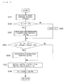
- Fig. 2 is a diagram illustrating an overall control flow of the refrigeration cycle apparatus according to Embodiment 1 of the present invention. The overall control flow is described below based on each of the steps of Fig. 2 .
- the controller 50 calculates a base opening degree (LPbase).
- the controller 50 calculates a predicted value Tc* of the condensing temperature and a predicted value Te* of the evaporating temperature after the compressor 1 is started or after the operating capacity of the compressor 1 is changed. Further, the controller 50 calculates the base opening degree LPbase to be set for the expansion valve 3 based on the predicted value Tc* of the condensing temperature, the predicted value Te* of the evaporating temperature, and a setting value of the operating capacity to be set for the compressor 1 (hereinafter referred to as "compressor capacity VP"). This calculation is described in more detail later.
- the controller 50 determines whether or not an actual measured value Te of the current evaporating temperature is less than a value obtained by subtracting a predetermined temperature (e.g., 5 degrees C) from the predicted value Te* of the evaporating temperature.
- a predetermined temperature e.g., 5 degrees C
- the actual measured value Te of the evaporating temperature can be calculated by converting the suction pressure Ps detected by the suction pressure sensor 43 into a refrigerant saturated gas temperature. Note that, a temperature sensor for detecting the evaporating temperature may also be separately provided.
- a predetermined temperature is subtracted from the predicted value Te* of the evaporating temperature
- This step may also be made by determining whether or not the actual measured value Te of the evaporating temperature is less than the predicted value Te*.
- the controller 50 When the actual measured value Te of the current evaporating temperature is less than the value obtained by subtracting the predetermined temperature from the predicted value Te* of the evaporating temperature, the controller 50 performs low-pressure correction control.
- the controller 50 calculates a predicted value ⁇ P* of a pressure difference between the condensing pressure of the condensor and the evaporating pressure of the evaporator based on the predicted value Tc* of the condensing temperature and the predicted value Te* of the evaporating temperature. Further, the controller 50 calculates a low-pressure correction opening degree ⁇ LPte for correcting the opening degree of the expansion valve 3 based on an actual measured value ⁇ P of the pressure difference between the condensing pressure of the condensor and the evaporating pressure of the evaporator and on the predicted value ⁇ P* of the pressure difference. These calculations are described in more detail later.
- the controller 50 sets the low-pressure correction opening degree ⁇ LPte to zero, and the processing proceeds to Step S106.
- the controller 50 determines whether or not the actual measured value Te of the evaporating temperature is larger than a value obtained by subtracting a predetermined temperature (e.g., 3 degrees C) from the predicted value Te* of the evaporating temperature. Alternatively, the controller 50 determines whether or not the absolute value of a difference between a setting opening degree LP of the expansion valve 3 and the base opening degree LPbase is less than a predetermined ratio (e.g., 30%) of the base opening degree LPbase. When this condition is satisfied, the processing proceeds to Step S106 and the controller 50 performs Td correction control. On the other hand, when this condition is not satisfied, the processing proceeds to Step S107.
- a predetermined temperature e.g. 3 degrees C
- the controller 50 performs the Td correction control.
- the controller 50 performs the Td correction control.
- the controller 50 calculates a target value Tdm for the discharge temperature of the refrigerant to be discharged from the compressor 1 based on the predicted value Tc* of the condensing temperature, the predicted value Te* of the evaporating temperature, and the compressor capacity VP. Further, the controller 50 calculates a Td correction opening degree ⁇ LPtd for correcting the opening degree of the expansion valve 3 based on a difference between the actual measured value of the discharge temperature Td detected by the discharge temperature sensor 41 and the target value Tdm for the discharge temperature. These calculations are described in more detail later.
- the controller 50 updates a correction opening degree ⁇ LPho by adding the low-pressure correction opening degree ⁇ LPte and the Td correction opening degree ⁇ LPtd to the current correction opening degree ⁇ LPho. Note that, the initial value of the correction opening degree ⁇ LPho is zero.
- the controller 50 calculates the setting opening degree LP by adding the correction opening degree ⁇ LPho to the base opening degree LPbase, and then sets the opening degree of the expansion valve 3 to the setting opening degree LP. The processing then returns to Step S101, and the operations described above are repeated.
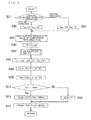
- the controller 50 determines whether the current operating state is the heating operation or the cooling operation. When the current operating state is determined to be the cooling operation, the processing proceeds to Step S202. When the current operating state is determined to be the heating operation, the processing proceeds to Step S203.
- the controller 50 acquires an outside air temperature AT detected by the outdoor temperature sensor 44 as the condensor suction air temperature Tac. Further, the controller 50 acquires an indoor temperature Tr detected by the indoor temperature sensor 45 as the evaporator suction air temperature Tae.
- the controller 50 acquires the outside air temperature AT detected by the outdoor temperature sensor 44 as the evaporator suction air temperature Tae. Further, the controller 50 acquires the indoor temperature Tr detected by the indoor temperature sensor 45 as the condensor suction air temperature Tac.
- the controller 50 When starting the compressor 1 or changing the operating capacity of the compressor 1, the controller 50 reads a control instruction value of a frequency f to be set for the compressor 1.
- the controller 50 calculates the setting value of the operating capacity (compressor capacity VP [cc x Hz]) to be set for the compressor 1 when starting the compressor 1 or when changing the operating capacity of the compressor 1 by multiplying the frequency f (Hz) by a displacement Vst [cc] of the compressor 1.
- the displacement Vst which is a value unique to the compressor 1, is stored in advance in the ROM and the like.
- the controller 50 calculates ⁇ Te and ⁇ Tc.
- the evaporating temperature Te is lower than the evaporator suction air temperature Tae by ⁇ Te.
- the condensing temperature Tc is higher than the condensor suction air temperature Tac by ⁇ Tc.
- ⁇ Te is a predicted value of the difference between the evaporating temperature Te and the evaporator suction air temperature Tae during stable operation after the compressor 1 is started or after the operating capacity of the compressor 1 is changed.
- ⁇ Tc is a predicted value of the difference between the condensing temperature Tc and the condensor suction air temperature Tac during stable operation after the compressor 1 is started or after the operating capacity of the compressor 1 is changed.
- Expression (1) and Expression (2) hold from the energy balance between the refrigerant and the air (heat medium) in the evaporator.
- VP ⁇ ⁇ s ⁇ ⁇ v ⁇ ⁇ ⁇ he AK ⁇ ⁇ ⁇ Te
- the controller 50 calculates ⁇ Te by substituting the compressor capacity VP into Expression (4).
- the controller 50 calculates ⁇ Tc by substituting the compressor capacity VP into Expression (7).
- the controller 50 calculates the predicted value Te* of the evaporating temperature by substituting the current evaporator suction air temperature Tae and the calculated ⁇ Te into Expression (8).
- Te * Tae - ⁇ ⁇ Te
- the controller 50 determines a base Cv value (Cv_b) of the expansion valve 3 based on the predicted value Tc* of the condensing temperature, the predicted value Te* of the evaporating temperature, and the compressor capacity VP.
- the controller 50 calculates ⁇ P* by converting the predicted value Tc* of the condensing temperature and the predicted value Te* of the evaporating temperature into a condensing pressure Pd and an evaporating pressure Ps using a saturation temperature.
- ⁇ l is taken to be the liquid density (fixed) based on the assumption that the refrigerant at the inlet of the expansion valve 3 is in a liquid state. Note that, ⁇ v is assumed to be fixed (unique value).
- the controller 50 calculates the base Cv value (Cv_b) of the expansion valve 3 by substituting these values into Expression (12).
- the controller 50 calculates the target value Tdm for the discharge temperature of the refrigerant to be discharged from the compressor 1 based on the predicted value Tc* of the condensing temperature, the predicted value Te* of the evaporating temperature, and the compressor capacity VP.
- a theoretical value, test data, or the like of a characteristic of the discharge temperature Td for the condensing temperature Tc, the evaporating temperature Te, and the compressor capacity VP when the degree of suction superheat of the compressor 1 is zero is stored in advance as a table in the ROM, for example.
- the discharge temperature Td corresponding to the predicted value Tc, the predicted value Te*, and the compressor capacity VP is set as the target value Tdm for the discharge temperature by referring to this table.
- the target value Tdm for the discharge temperature is the discharge temperature Td when the degree of suction superheat of the compressor 1 is zero.
- the controller 50 determines whether or not the target value Tdm for the discharge temperature calculated in Step S209 is more than a discharge temperature maximum permitted value Tdmax.
- the discharge temperature maximum permitted value Tdmax which is a value unique to the compressor 1, is stored in advance in the ROM and the like.
- the controller 50 calculates a Cv correction value ⁇ Cvtd based on a difference between the target value Tdm for the discharge temperature and the discharge temperature maximum permitted value Tdmax.
- the Cv correction value ⁇ Cvtd is a value greater than zero. As the difference between the target value Tdm for the discharge temperature and the discharge temperature maximum permitted value Tdmax becomes larger, the larger value is set as the Cv correction value ⁇ Cvtd. In other words, when the target value Tdm for the discharge temperature is more than the discharge temperature maximum permitted value Tdmax, the Cv value is corrected so that the opening degree of the expansion valve 3 increases to prevent the discharge temperature Td after startup from being equal to or more than the discharge temperature maximum permitted value Tdmax.
- the controller 50 sets the Cv correction value ⁇ Cvtd to zero, and the processing proceeds to Step S213.
- the controller 50 calculates a base opening degree LPbase by converting a value obtained by adding the Cv correction value ⁇ Cvtd to the base Cv value (Cv_b) of the expansion valve 3 using a conversion function fLEV for converting the Cv value into the setting opening degree LP.
- the Cv value [-] and the setting opening degree LP [pulse] have a correspondence relationship unique to the expansion valve 3. Such a correspondence relationship is approximated and stored in the ROM in advance as the conversion function fLEV. Note that, the correspondence relationship between the setting opening degree LP and the Cv value may also be stored as table information.
- the controller 50 then finishes the base opening degree calculation, and the processing proceeds to Step S102 ( Fig. 2 ).
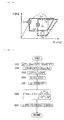
- Fig. 6 is a p-h diagram showing low-pressure correction control of the refrigeration cycle apparatus according to Embodiment 1 of the present invention.
- Fig. 7 is a diagram illustrating a low-pressure correction control flow of the refrigeration cycle apparatus according to Embodiment 1 of the present invention.
- the above-mentioned base opening degree LPbase is an opening degree calculated based on the assumption that the refrigerant at the inlet of the expansion valve 3 is in a liquid state.
- the refrigerant at the inlet of the expansion valve 3 is in a two-phase gas-liquid state, the refrigerant density is less than that for a liquid state.
- pressure loss increases, which can lead to a decrease in the refrigerant pressure on the low-pressure side (drawing-in of low-pressure).
- the solid line represents a refrigerant circuit in which the refrigerant at the inlet of the expansion valve 3 is in a liquid state when the pressure on the low-pressure side (predicted value Tc* and predicted value Te*) is stable.
- the dotted line represents a refrigerant circuit in which the refrigerant at the inlet of the expansion valve 3 is in a two-phase gas-liquid state when the pressure on the low-pressure side has decreased.
- the controller 50 determines that the refrigerant at the inlet of the expansion valve 3 is in a two-phase gas-liquid state (low density) (S102), and performs low-pressure correction control. Further, the controller 50 also suppresses the decrease in pressure on the low-pressure side by correcting the opening degree of the expansion valve 3 so that the condensing temperature is the predicted value Tc* and the evaporating temperature is the predicted value Te*.
- S102 two-phase gas-liquid state
- the controller 50 calculates the predicted value ⁇ P* of the high/low pressure difference based on the predicted value Tc* of the condensing temperature and the predicted value Te* of the evaporating temperature. For example, the predicted value Tc* of the condensing temperature is converted into the condensing pressure Pd and the predicted value Te* of the evaporating temperature is converted into the evaporating pressure Ps using their respective saturation temperatures. Then, the predicted value ⁇ P* of the high/low pressure difference is calculated based on the difference between the condensing pressure Pd and the evaporating pressure Ps.
- the controller 50 calculates the actual measured value ⁇ P of the high/low pressure difference based on the difference between the discharge pressure Pd detected by the discharge pressure sensor 42 and the suction pressure Ps detected by the suction pressure sensor 43.
- the actual measured value ⁇ P of the high/low pressure difference may also be calculated by separately providing a temperature sensor for detecting the condensing temperature and a temperature sensor for detecting the evaporating temperature, and converting the measured temperatures into the respective pressure values.
- the controller 50 calculates ⁇ s* using the predicted value Te*.
- the controller 50 calculates ps using the actual measured value Te of the current evaporating temperature based on the relationship in Expression (3).
- the actual measured value Te of the evaporating temperature can be calculated by converting the suction pressure Ps detected by the suction pressure sensor 43 into a refrigerant saturated gas temperature. Note that, a temperature sensor for detecting the evaporating temperature may also be separately provided.
- the controller 50 converts the current setting opening degree LP into a Cv value using the conversion function fLEVCv for converting the setting opening degree LP into a Cv value.
- the conversion function fLEVCv may be determined based on the correspondence relationship between the Cv value [-] and the setting opening degree LP [pulse], or may be stored as table information.
- the controller 50 calculates the Cvte, which is the corrected Cv value, by substituting each of the values calculated in Step S301 to Step S305 into Expression (15).
- the controller 50 calculates the difference between a value obtained by converting the Cvte into an opening degree setting value and a value obtained by converting the current Cv value into an opening degree setting value as the low-pressure correction opening degree ⁇ LPte.
- the controller 50 then finishes the low-pressure correction control, and the processing proceeds to Step S105 ( Fig. 2 ).
- Fig. 8 is a diagram illustrating a Td correction control flow of the refrigeration cycle apparatus according to Embodiment 1 of the present invention. The control flow is described below based on each of the steps of Fig. 8 .
- the controller 50 calculates the target value Tdm for the discharge temperature of the refrigerant to be discharged from the compressor 1 based on the predicted value Tc* of the condensing temperature, the predicted value Te* of the evaporating temperature, and the compressor capacity VP.
- the theoretical value, test data, or the like of a characteristic of the discharge temperature Td for the condensing temperature Tc, the evaporating temperature Te, and the compressor capacity VP when the degree of suction superheat of the compressor 1 is zero is stored in advance as a table in the ROM, for example.
- the discharge temperature Td corresponding to the predicted value Tc, the predicted value Te*, and the compressor capacity VP is set as the target value Tdm for the discharge temperature by referring to this table.
- the target value Tdm for the discharge temperature is the discharge temperature Td when the degree of suction superheat of the compressor 1 is zero.
- the controller 50 calculates the Cv correction value ⁇ Cvtd based on the difference between the current discharge temperature Td detected by the discharge temperature sensor 41 and the target value Tdm for the discharge temperature.
- the Cv correction value ⁇ Cvtd is a value greater than zero. As the difference between the current discharge temperature Td and the target value Tdm for the discharge temperature becomes larger, the larger value is set as the Cv correction value ⁇ Cvtd.
- the Cv correction value ⁇ Cvtd when the discharge temperature Td is more than the target value Tdm, the Cv correction value ⁇ Cvtd is set to a positive value, and when the discharge temperature Td is less than the target value Tdm, the Cv correction value ⁇ Cvtd is set to a negative value.
- the discharge temperature Td is controlled to be at the target value Tdm by increasing the opening degree of the expansion valve 3 when the actual measured value of the discharge temperature Td is more than the target value Tdm, and decreasing the opening degree of the expansion valve 3 when the actual measured value of the discharge temperature Td is less than the target value Tdm.
- the controller 50 converts a value calculated by adding ⁇ Cvtd to the current Cv value into an opening degree setting value and converts the current Cv value into an opening degree setting value, and calculates the difference between the opening degree setting values obtained by the conversion as the Td correction opening degree ⁇ LPtd.
- the controller 50 then finishes the Td correction control, and the processing proceeds to Step S107 ( Fig. 2 ).
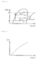
- Fig. 9 is a diagram showing examples of operation results of the refrigeration cycle apparatus according to Embodiment 1 of the present invention.
- the base opening degree of the expansion valve 3 when the compressor 1 is started or when the compressor capacity VP is changed is a value that is proportional to the compressor capacity VP.
- the controller 50 determines that the refrigerant at the inlet of the expansion valve 3 is in a two-phase gas-liquid state (low density), and performs low-pressure correction control. As a result, the opening degree of the expansion valve 3 is increased by the low-pressure correction opening degree ⁇ LPte, and the decrease in the pressure on the low-pressure side is suppressed.
- Td correction control is performed.
- the discharge temperature Td is controlled to be at the target value Tdm by increasing or decreasing the opening degree of the expansion valve 3 by the Td correction opening degree ⁇ LPtd.
- the controller 50 when starting the compressor 1 or when changing the operating capacity of the compressor 1, calculates the predicted value Tc* of the condensing temperature of the refrigerant and the predicted value Te* of the evaporating temperature of the refrigerant after the compressor 1 is started or after the operating capacity of the compressor 1 is changed based on the condensor suction air temperature Tac, the evaporator suction air temperature Tae, and the compressor capacity VP. Further, the controller 50 determines the opening degree to be set for the expansion valve 3 based on the predicted value Tc* of the condensing temperature, the predicted value Te* of the evaporating temperature, and the compressor capacity VP.
- the appropriate opening degree of the expansion valve 3 can be set based on the environmental conditions and the compressor capacity VP.
- liquid can be prevented from flowing back into the compressor 1, allowing device reliability to be improved.
- the predicted value Tc* and the predicted value Te* after the compressor 1 is started or after the operating capacity of the compressor 1 is changed are calculated, and hence the quick response of the opening degree control of the expansion valve 3 can be improved.
- the predicted value ⁇ P* of the pressure difference between the condensing pressure and the evaporating pressure is calculated based on the predicted value Tc* and the predicted value Te*
- the actual measured value ⁇ P of the pressure difference between the condensing pressure and the evaporating pressure is calculated based on the condensor suction air temperature Tac and the evaporator suction air temperature Tae.
- the opening degree to be set for the expansion valve 3 is corrected by calculating the low-pressure correction opening degree ⁇ LPte based on the predicted value ⁇ P* of the pressure difference and the actual measured value ⁇ P of the pressure difference.
- the decrease in the refrigerant pressure on the low-pressure side (drawing-in of low-pressure) that occurs under an environmental condition in which the outside air temperature is low can be suppressed. Further, suppressing the decrease in the refrigerant pressure on the low-pressure side enables the refrigerant circuit amount to be increased, and hence the heating capacity to be improved. In addition, suppressing the drawing-in of low pressure during startup at a low outside air temperature enables deterioration in the operating efficiency to be suppressed, and hence enables energy savings to be improved.
- the controller 50 calculates the target value Tdm for the discharge temperature of the refrigerant to be discharged from the compressor 1 after the operating capacity of the compressor 1 is changed based on the predicted value Tc*, the predicted value Te*, and the compressor capacity VP. In addition, the controller 50 calculates the Td correction opening degree ⁇ LPtd, and corrects the opening degree to be set for the expansion valve 3 based on the difference between the actual measured value of the discharge temperature Td and the target value Tdm.
- the controller 50 corrects the opening degree to be set for the expansion valve 3 based on the difference between the discharge temperature maximum permitted value Tdmax and the target value Tdm.
- the startup operation can be performed within the permitted operating range because of a wet suction operation of the compressor 1.
- the base opening degree calculation (S101), low-pressure correction control (S103), and Td correction control (S106) are performed as the control operation for setting the opening degree of the expansion valve 3.
- the present invention is not limited to this embodiment.
- the control may be performed by executing an arbitrary one or two of the base opening degree calculation, low-pressure correction control, and Td correction control.
- the opening degree of the expansion valve 3 may be set by omitting Step S102 to Step S104, and just calculating the base opening degree and performing the Td correction control. Further, for example, in Fig. 2 , the opening degree of the expansion valve 3 may be set by omitting Step S105 and Step S106, and just calculating the base opening degree and performing the low-pressure correction control. Still further, for example, in Fig. 2 , the opening degree of the expansion valve 3 may be set by omitting Step S102 to Step S107, and just calculating the base opening degree. Still even further, for example, in Fig. 2 , the opening degree of the expansion valve 3 may be corrected by omitting Step S101, setting the base opening degree to an arbitrary opening degree, and then performing the low-pressure correction control and the low-pressure correction control.
Landscapes
- Engineering & Computer Science (AREA)
- Physics & Mathematics (AREA)
- Mechanical Engineering (AREA)
- Thermal Sciences (AREA)
- General Engineering & Computer Science (AREA)
- Air Conditioning Control Device (AREA)
Abstract
Description
- The present invention relates to a refrigeration cycle apparatus for circulating refrigerant through a circuit in which a compressor, a condensor, an expansion valve, and an evaporator are connected to each other by pipes, and a method of controlling a refrigeration cycle apparatus.
- In a related-art refrigeration cycle apparatus, there has been proposed one having a structure in which, for example, an opening degree of an expansion valve during startup of a heating operation is set to a pre-set startup opening degree, and when a low-pressure refrigerant pressure is a predetermined pressure or more, the opening degree of the expansion valve is set to be decreased to less than that of the startup opening degree, and when the low-pressure refrigerant pressure is less than the predetermined pressure, the opening degree of the expansion valve is set to be increased (e.g., see Patent Literature 1).
- Further, there has also been proposed one having a structure in which, during startup operation, the opening degree of the expansion valve is increased when refrigerant flowing into an evaporator is determined to be in a superheated gaseous state (e.g., see Patent Literature 2).
- In addition, there has also been proposed one having a structure in which changes in a discharge pipe temperature of a compressor are monitored, and the opening degree of the expansion valve for the next startup is set by learning the opening degree of the expansion valve based on the changes in the discharge pipe temperature (e.g., see Patent Literature 3).
- Still further, there has also been proposed one having a structure in which the opening degree of the expansion valve is controlled to be adjusted in steps based on an outside air temperature condition to reach a set opening degree that matches a frequency set to the compressor (e.g., see Patent Literature 4).
-
- Patent Literature 1: Japanese Patent No.
3208923 - Patent Literature 2: Japanese Patent No.
5022920 - Patent Literature 3: Japanese Unexamined Patent Application Publication No.
Hei 11-153366 - Patent Literature 4: Japanese Unexamined Patent Application Publication No.
2000-337717 - When operation of the refrigeration cycle apparatus is started under an environmental condition in which the outside air temperature is low, because the refrigerant has turned into a liquid state and accumulated in devices (such as an evaporator and accumulator) in an outdoor unit while operation was stopped, the refrigerant flowing into the expansion valve during startup turns into a two-phase gas-liquid phase, causing the refrigerant density to decrease. As a result, during operation immediately after startup, the refrigerant pressure on the low-pressure side decreases, causing a problem in the circulation of refrigerating machine oil.
- Further, when operation of the refrigeration cycle apparatus is started under an environmental condition in which the outside air temperature is high, operation is under a high compression ratio, and hence the discharge temperature at the compressor during startup tends to increase excessively. When the discharge temperature increases excessively, the refrigerating machine oil deteriorates, and the heat resistance of a compressor coil deteriorates.
- In the related art, a large startup opening degree is set for the expansion valve, and after a predetermined period of time has elapsed that allows subcooling (SC) on an inlet side of the expansion valve to be achieved, normal controls, namely, discharge temperature control and indoor unit SC control, are started.
- However, depending on changes in the environmental conditions, such as when the outside air temperature is different from that expected, changes in the operating capacity of the compressor, or other changes, there has been a problem with liquid flowing back into the compressor. As a result, there has been a problem in that operating efficiency and device reliability deteriorate.
- Further, conversely, when the startup opening degree is too small, there has been a problem in that the refrigerant pressure on the low-pressure side decreases, and the discharge temperature (Td) at the compressor increases excessively, causing operating efficiency and device reliability to deteriorate. In particular, this problem is noticeable for the refrigerant R32, which is a refrigerant having a low global warming potential (GWP), with the discharge temperature (Td) tending to increase by about 15 K to 30 K more than that of the currently used refrigerant R410A.
- In the technologies disclosed in Patent Literatures 1 to 4, no consideration is given to an effect on the refrigerant pressure on a high-pressure side or on the discharge temperature resulting from the opening degree control of the expansion valve. As a result, depending on the environmental conditions, there has been a problem in that the discharge temperature of the compressor increases excessively, causing operating efficiency and device reliability to deteriorate.
- Further, in the technology disclosed in
Patent Literature 2, there has been a problem in that control response is slow due to a response lag caused by performing the opening degree control of the expansion valve after the determination that the refrigerant flowing into the evaporator is in a superheated gaseous state. In addition, in the technology disclosed inPatent Literature 3, there has been a problem in that control response is slow because the opening degree of the expansion valve for the next startup needs to be learned. - The present invention has been made to solve the above-mentioned problems. An object of the present invention is to provide a refrigeration cycle apparatus and a method of controlling a refrigeration cycle apparatus that are capable of setting an appropriate opening degree of an expansion valve based on environmental conditions and an operating capacity of a compressor.
- Further, an object of the present invention is to provide a refrigeration cycle apparatus and a method of controlling a refrigeration cycle apparatus that are capable of improving operating efficiency by suppressing a decrease in a refrigerant pressure on a low-pressure side under an environmental condition in which an outside air temperature is low.
- In addition, an object of the present invention is to provide a refrigeration cycle apparatus and a method of controlling a refrigeration cycle apparatus that are capable of improving device reliability by suppressing an excessive increase in a discharge temperature at the compressor.
- Still further, an object of the present invention is to provide a refrigeration cycle apparatus and a method of controlling a refrigeration cycle apparatus that are capable of improving the quick response of opening degree control of the expansion valve.
- According to one embodiment of the present invention, there is provided a refrigeration cycle apparatus for circulating refrigerant through a circuit in which a compressor having a changeable operating capacity, a condensor, an expansion valve having a changeable opening degree, and an evaporator are connected to each other by pipes, the refrigeration cycle apparatus including: a first temperature sensor for detecting a temperature of a heat medium to be subjected to heat exchange with the refrigerant in the condensor; a second temperature sensor for detecting a temperature of a heat medium to be subjected to heat exchange with the refrigerant in the evaporator; and a controller for controlling the operating capacity of the compressor and the opening degree of the expansion valve, the controller being configured to, when starting the compressor or when changing the operating capacity of the compressor, calculate a predicted value (Tc*) of a condensing temperature of the refrigerant and a predicted value (Te*) of an evaporating temperature of the refrigerant being predicted after the compressor is started or after the operating capacity of the compressor is changed, based on a detection value of the first temperature sensor, a detection value of the second temperature sensor, and a setting value (VP) of the operating capacity to be set for the compressor, and determine the opening degree to be set for the expansion valve based on the predicted value (Tc*) of the condensing temperature, the predicted value (Te*) of the evaporating temperature, and the setting value (VP) of the operating capacity to be set for the compressor.
- The one embodiment of the present invention is capable of setting the appropriate opening degree of the expansion valve based on the environmental conditions and the operating capacity of the compressor.
- Further, the one embodiment of the present invention is capable of improving the operating efficiency by suppressing the decrease in the refrigerant pressure on the low-pressure side under the environmental condition in which the outside air temperature is low.
- In addition, the one embodiment of the present invention is capable of improving the device reliability by suppressing the excessive increase in the discharge temperature at the compressor.
- Still further, the one embodiment of the present invention is capable of improving the quick response of the opening degree control of the expansion valve.
-
- [
Fig. 1] Fig. 1 is a configuration diagram of a refrigeration cycle apparatus according to Embodiment 1 of the present invention. - [
Fig. 2] Fig. 2 is a diagram illustrating an overall control flow of the refrigeration cycle apparatus according to Embodiment 1 of the present invention. - [
Fig. 3] Fig. 3 is a p-h diagram of the refrigeration cycle apparatus according to Embodiment 1 of the present invention. - [
Fig. 4] Fig. 4 is a diagram showing a relationship between an opening degree of an expansion valve and a Cv value. - [
Fig. 5] Fig. 5 is a diagram illustrating a base opening degree calculation flow of the refrigeration cycle apparatus according to Embodiment 1 of the present invention. - [
Fig. 6] Fig. 6 is a p-h diagram showing low-pressure correction control of the refrigeration cycle apparatus according to Embodiment 1 of the present invention. - [
Fig. 7] Fig. 7 is a diagram illustrating a low-pressure correction control flow of the refrigeration cycle apparatus according to Embodiment 1 of the present invention. - [
Fig. 8] Fig. 8 is a diagram illustrating a Td correction control flow of the refrigeration cycle apparatus according to Embodiment 1 of the present invention. - [
Fig. 9] Fig. 9 is a diagram showing examples of operation results of the refrigeration cycle apparatus according to Embodiment 1 of the present invention. -
Fig. 1 is a configuration diagram of a refrigeration cycle apparatus according to Embodiment 1 of the present invention. - As illustrated in
Fig. 1 , arefrigeration cycle apparatus 100 includes anoutdoor unit 61 and anindoor unit 62. Theoutdoor unit 61 and theindoor unit 62 are connected to each other by a liquid pipe 5 and agas pipe 7, forming arefrigerant circuit 20, which is described later. Theoutdoor unit 61 transfers heat to or removes heat from a heat source, such as outside air. Theindoor unit 62 transfers heat to or removes heat from a load, such as indoor air. Note that, although only oneindoor unit 62 is illustrated inFig. 1 , a plurality ofindoor units 62 may be employed. - The
outdoor unit 61 includes a compressor 1, a four-way valve 8, which is a flow switching device, anoutdoor heat exchanger 2 for exchanging heat with a heat medium, such as outside air or water, and anexpansion valve 3, which is a pressure reducing device. These parts are connected to each other by a refrigerant pipe. Theoutdoor unit 61 further includes anoutdoor fan 31, which is a device for conveying the heat medium, such as outside air or water, to theoutdoor heat exchanger 2. Each of the parts included in theoutdoor unit 61 is described below in order. - The compressor 1 is, for example, a hermetically sealed compressor, and capable of changing its rotation speed with an inverter based on a command from a
controller 50. Thecontroller 50 is configured to adjust a flow rate of refrigerant circulating through therefrigerant circuit 20 by controlling the rotation speed of the compressor 1 based on an air-conditioning load or other conditions. As a result, the amount of heat that is transferred or removed in theindoor unit 62 is adjusted, and when the load side is the indoor air, for example, the indoor air temperature can be appropriately maintained. - The four-
way valve 8 is used to switch passages so that gas refrigerant discharged from the compressor 1 flows to theoutdoor heat exchanger 2 or to anindoor heat exchanger 6. By switching passages with the four-way valve 8, for example, theoutdoor heat exchanger 2 can be made to function as a condensor (radiator) or to function as an evaporator. - The
outdoor heat exchanger 2 is, for example, a fin-and-tube heat exchanger, and for exchanging heat between outside air as a heat medium supplied from theoutdoor fan 31 and the refrigerant. Note that, the heat medium exchanging heat with the refrigerant in theoutdoor heat exchanger 2 is not limited to outside air (air). For example, water and a non-frozen liquid may also be used as the heat source. In this case, a plate heat exchanger is used for theoutdoor heat exchanger 2, and a pump instead of theoutdoor fan 31 is used as a heat source-side conveying device. Further, theoutdoor heat exchanger 2 may also be configured to supply a heat source having a stable temperature throughout the year by using geothermal heat drawn from heat-exchanging pipes buried in the ground. - The
expansion valve 3 is a valve capable of changing the opening degree based on a command from thecontroller 50. As theexpansion valve 3, for example, an electronically-controlled expansion valve (linear expansion valve: LEV) may be used. The passage resistance is changed by changing the opening degree of theexpansion valve 3. The operation for setting the opening degree of theexpansion valve 3 is described later. - The
indoor unit 62 includes theindoor heat exchanger 6 for exchanging heat with a heat medium, such as indoor air, and anindoor fan 32, which is a device for conveying the heat medium, such as indoor air. Each of the parts included in theindoor unit 62 is described below in order. - The
indoor heat exchanger 6 is, for example, a fin-and-tube heat exchanger, and for exchanging heat between indoor air as a heat medium supplied from theindoor fan 32 and the refrigerant. Note that, the heat medium exchanging heat with the refrigerant in theindoor heat exchanger 6 is not limited to indoor air. For example, water and a non-frozen liquid may also be used as the heat source. In this case, a plate heat exchanger is used for theindoor heat exchanger 6, and a pump instead of theindoor fan 32 is used as a load-side conveying device. - The liquid pipe 5 and the
gas pipe 7, which are connecting pipes connecting theoutdoor unit 61 and theindoor unit 62, each have a predetermined length that is necessary for connection. Further, thegas pipe 7 usually has a larger pipe diameter than the liquid pipe 5. The liquid pipe 5 connects between theexpansion valve 3 of theoutdoor unit 61 and theindoor heat exchanger 6 of theindoor unit 62. Thegas pipe 7 connects between the four-way valve 8 of theoutdoor unit 61 and theindoor heat exchanger 6 of theindoor unit 62. Connecting theoutdoor unit 61 and theindoor unit 62 to each other in this manner by the liquid pipe 5 and thegas pipe 7 forms therefrigerant circuit 20. In therefrigerant circuit 20, refrigerant circulates through, in order, the compressor 1, the four-way valve 8, theindoor heat exchanger 6, theexpansion valve 3, theoutdoor heat exchanger 2, and the four-way valve 8. - Next, sensors and the
controller 50 included in therefrigeration cycle apparatus 100 are described. - A
discharge temperature sensor 41 for detecting the temperature of the refrigerant discharged from the compressor 1 (hereinafter referred to as "discharge temperature Td") is arranged on the discharge side of the compressor 1. Adischarge pressure sensor 42 for detecting the pressure of the refrigerant discharged from the compressor 1 (hereinafter referred to as "discharge pressure Pd") is arranged on the discharge side of the compressor 1. Asuction pressure sensor 43 for detecting the pressure of the refrigerant discharged from the compressor 1 (hereinafter referred to as "suction pressure Ps") is arranged on the suction side of the compressor 1. - The
outdoor unit 61 includes anoutdoor temperature sensor 44 for detecting the temperature of the air (outside air) to be subjected to heat exchange with the refrigerant in theoutdoor heat exchanger 2. Theindoor unit 62 includes anindoor temperature sensor 45 for detecting the temperature of the air (indoor air) to be subjected to heat exchange with the refrigerant in theindoor heat exchanger 6. - In other words, during a heating operation, the
outdoor temperature sensor 44 detects the temperature of the air being sucked into the evaporator (evaporator suction air temperature Tae), and theindoor temperature sensor 45 detects the temperature of the air being sucked into the condensor (condensor suction air temperature Tac). Further, during a cooling operation, theoutdoor temperature sensor 44 detects the temperature of the air being sucked into the condensor (condensor suction air temperature Tac), and theindoor temperature sensor 45 detects the temperature of the air being sucked into the evaporator (evaporator suction air temperature Tae). - Note that, of the
outdoor temperature sensor 44 and theindoor temperature sensor 45, the sensor detecting the condensor suction air temperature Tac corresponds to a "first temperature sensor" in the present invention. - Further, of the
outdoor temperature sensor 44 and theindoor temperature sensor 45, the sensor detecting the evaporator suction air temperature Tae corresponds to a "second temperature sensor" in the present invention. - In addition, the
discharge temperature sensor 41 corresponds to a "third temperature sensor" in the present invention. - The
controller 50, which is configured from a microcomputer, includes a central processing unit (CPU), a random-access memory (RAM), a read-only memory (ROM), and the like. The ROM stores a control program, programs corresponding to flowcharts that are described later, and the like. Thecontroller 50 controls the compressor 1, theexpansion valve 3, theoutdoor fan 31, and theindoor fan 32 based on detection values from the respective sensors. Further, thecontroller 50 performs a cooling operation or a heating operation by switching the four-way valve 8. Note that, thecontroller 50 may be included in theoutdoor unit 61, or may be included in theindoor unit 62, or may even be divided into an outdoor control device and an indoor control device that are configured to perform processing cooperatively together. - Next, behaviors on the
refrigerant circuit 20 during the heating operation and the cooling operation are described. - During the heating operation, the four-
way valve 8 is switched to a state indicated by the solid lines inFig. 1 . High-temperature, high-pressure refrigerant discharged from the compressor 1 passes through the four-way valve 8 and flows into thegas pipe 7. The refrigerant then flows into theindoor heat exchanger 6 of theindoor unit 62. Theindoor heat exchanger 6 acts as a condensor during the heating operation, and hence the refrigerant that has flowed into theindoor heat exchanger 6 exchanges heat with the indoor air from theindoor fan 32, thereby transferring heat into a room. As a result, the temperature of the refrigerant decreases, turning the refrigerant into a subcooled liquid refrigerant, which flows out of theindoor heat exchanger 6. - The refrigerant that has flowed out of the
indoor heat exchanger 6 flows into the liquid pipe 5, and then into theoutdoor unit 61. The pressure of the refrigerant that has flowed into theoutdoor unit 61 is reduced by theexpansion valve 3, turning the refrigerant into a two-phase gas-liquid refrigerant, which flows into theoutdoor heat exchanger 2. Theoutdoor heat exchanger 2 acts as an evaporator during the heating operation, and hence the refrigerant that has flowed into theoutdoor heat exchanger 2 removes heat through heat exchange with the outside air blown from theoutdoor fan 31. This causes the refrigerant to evaporate, turning into gaseous state refrigerant, which flows out of theoutdoor heat exchanger 2. The refrigerant that has flowed out of theoutdoor heat exchanger 2 passes through the four-way valve 8 and is sucked into the compressor 1. - During the cooling operation, the four-
way valve 8 is switched to a state indicated by the dotted lines inFig. 1 . High-temperature, high-pressure refrigerant discharged from the compressor 1 passes through the four-way valve 8 and flows into theoutdoor heat exchanger 2. The refrigerant flowing into theoutdoor heat exchanger 2 is in a refrigerant state that is roughly the same as the high-temperature, high-pressure refrigerant discharged from the compressor 1. Theoutdoor heat exchanger 2 acts as a condensor during the cooling operation, and hence the refrigerant that has flowed into theoutdoor heat exchanger 2 exchanges heat with the outside air from theoutdoor fan 31, thereby transferring heat to the outside. As a result, the temperature of the refrigerant decreases, turning the refrigerant into a subcooled liquid refrigerant, which flows out of theoutdoor heat exchanger 2. - The pressure of the refrigerant that has flowed out of the
outdoor heat exchanger 2 is reduced by theexpansion valve 3, turning the refrigerant into a two-phase gas-liquid refrigerant, which flows into the liquid pipe 5. The refrigerant then flows into theindoor heat exchanger 6 of theindoor unit 62. Theindoor heat exchanger 6 acts as an evaporator during the cooling operation, and hence the refrigerant that has flowed into theindoor heat exchanger 6 removes heat through heat exchange with the indoor air blown from theindoor fan 32. This causes the refrigerant to evaporate, turning into gaseous state refrigerant, which flows out of theindoor heat exchanger 6. The refrigerant that has flowed out of theindoor heat exchanger 6 flows into thegas pipe 7. The refrigerant that has flowed into thegas pipe 7 flows into theoutdoor unit 61. The refrigerant that has flowed into theoutdoor unit 61 passes through the four-way valve 8 and is sucked into the compressor 1. - The
refrigeration cycle apparatus 100 of Embodiment 1 is capable of switching between the heating operation and the cooling operation. However, the present invention is not limited to such a configuration. The present invention may also be configured to perform only the heating operation or only the cooling operation. In such a case, the four-way valve 8 may be omitted. - Next, a control operation for setting the opening degree of the
expansion valve 3 is described. - The control operation for setting the opening degree of the
expansion valve 3 can be broadly classified into a base opening degree calculation, low-pressure correction control, and Td correction control. Thecontroller 50 sets the opening degree of theexpansion valve 3 by sequentially performing the calculation and control operations when starting the compressor 1 or when changing the operating capacity of the compressor 1. - The overall control flow is first described below, and then the calculation and control operations are described in detail.
-
Fig. 2 is a diagram illustrating an overall control flow of the refrigeration cycle apparatus according to Embodiment 1 of the present invention. The overall control flow is described below based on each of the steps ofFig. 2 . - The
controller 50 calculates a base opening degree (LPbase). - In the base opening degree calculation, the
controller 50 calculates a predicted value Tc* of the condensing temperature and a predicted value Te* of the evaporating temperature after the compressor 1 is started or after the operating capacity of the compressor 1 is changed. Further, thecontroller 50 calculates the base opening degree LPbase to be set for theexpansion valve 3 based on the predicted value Tc* of the condensing temperature, the predicted value Te* of the evaporating temperature, and a setting value of the operating capacity to be set for the compressor 1 (hereinafter referred to as "compressor capacity VP"). This calculation is described in more detail later. - The
controller 50 determines whether or not an actual measured value Te of the current evaporating temperature is less than a value obtained by subtracting a predetermined temperature (e.g., 5 degrees C) from the predicted value Te* of the evaporating temperature. - The actual measured value Te of the evaporating temperature can be calculated by converting the suction pressure Ps detected by the
suction pressure sensor 43 into a refrigerant saturated gas temperature. Note that, a temperature sensor for detecting the evaporating temperature may also be separately provided. - Further, although in this example a predetermined temperature is subtracted from the predicted value Te* of the evaporating temperature, the present invention is not limited to this embodiment. This step may also be made by determining whether or not the actual measured value Te of the evaporating temperature is less than the predicted value Te*.
- When the actual measured value Te of the current evaporating temperature is less than the value obtained by subtracting the predetermined temperature from the predicted value Te* of the evaporating temperature, the
controller 50 performs low-pressure correction control. - In the low-pressure correction control, the
controller 50 calculates a predicted value ΔP* of a pressure difference between the condensing pressure of the condensor and the evaporating pressure of the evaporator based on the predicted value Tc* of the condensing temperature and the predicted value Te* of the evaporating temperature. Further, thecontroller 50 calculates a low-pressure correction opening degree ΔLPte for correcting the opening degree of theexpansion valve 3 based on an actual measured value ΔP of the pressure difference between the condensing pressure of the condensor and the evaporating pressure of the evaporator and on the predicted value ΔP* of the pressure difference. These calculations are described in more detail later. - When the actual measured value Te of the current evaporating temperature is not less than the value obtained by subtracting the predetermined temperature from the predicted value Te* of the evaporating temperature, the
controller 50 sets the low-pressure correction opening degree ΔLPte to zero, and the processing proceeds to Step S106. - The
controller 50 determines whether or not the actual measured value Te of the evaporating temperature is larger than a value obtained by subtracting a predetermined temperature (e.g., 3 degrees C) from the predicted value Te* of the evaporating temperature. Alternatively, thecontroller 50 determines whether or not the absolute value of a difference between a setting opening degree LP of theexpansion valve 3 and the base opening degree LPbase is less than a predetermined ratio (e.g., 30%) of the base opening degree LPbase. When this condition is satisfied, the processing proceeds to Step S106 and thecontroller 50 performs Td correction control. On the other hand, when this condition is not satisfied, the processing proceeds to Step S107. - In other words, when a deviation between the actual measured value Te of the evaporating temperature and the predicted value Te* of the evaporating temperature has decreased, or, when a deviation between the current setting opening degree LP and the base opening degree LPbase has decreased, the
controller 50 performs the Td correction control. - The
controller 50 performs the Td correction control. - In the Td correction control, the
controller 50 calculates a target value Tdm for the discharge temperature of the refrigerant to be discharged from the compressor 1 based on the predicted value Tc* of the condensing temperature, the predicted value Te* of the evaporating temperature, and the compressor capacity VP. Further, thecontroller 50 calculates a Td correction opening degree ΔLPtd for correcting the opening degree of theexpansion valve 3 based on a difference between the actual measured value of the discharge temperature Td detected by thedischarge temperature sensor 41 and the target value Tdm for the discharge temperature. These calculations are described in more detail later. - The
controller 50 updates a correction opening degree ΔLPho by adding the low-pressure correction opening degree ΔLPte and the Td correction opening degree ΔLPtd to the current correction opening degree ΔLPho. Note that, the initial value of the correction opening degree ΔLPho is zero. - The
controller 50 calculates the setting opening degree LP by adding the correction opening degree ΔLPho to the base opening degree LPbase, and then sets the opening degree of theexpansion valve 3 to the setting opening degree LP. The processing then returns to Step S101, and the operations described above are repeated. - Next, the base opening degree calculation, low-pressure correction control, and Td correction control are described in more detail.
-
-
Fig. 3 is a p-h diagram of the refrigeration cycle apparatus according to Embodiment 1 of the present invention. -
Fig. 4 is a diagram showing a relationship between the opening degree of the expansion valve and a Cv value. -
Fig. 5 is a diagram illustrating a base opening degree calculation flow of the refrigeration cycle apparatus according to Embodiment 1 of the present invention. The respective steps ofFig. 5 are described below with reference toFig. 3 and Fig. 4 . - The
controller 50 determines whether the current operating state is the heating operation or the cooling operation. When the current operating state is determined to be the cooling operation, the processing proceeds to Step S202. When the current operating state is determined to be the heating operation, the processing proceeds to Step S203. - The
controller 50 acquires an outside air temperature AT detected by theoutdoor temperature sensor 44 as the condensor suction air temperature Tac. Further, thecontroller 50 acquires an indoor temperature Tr detected by theindoor temperature sensor 45 as the evaporator suction air temperature Tae. - The
controller 50 acquires the outside air temperature AT detected by theoutdoor temperature sensor 44 as the evaporator suction air temperature Tae. Further, thecontroller 50 acquires the indoor temperature Tr detected by theindoor temperature sensor 45 as the condensor suction air temperature Tac. - When starting the compressor 1 or changing the operating capacity of the compressor 1, the
controller 50 reads a control instruction value of a frequency f to be set for the compressor 1. - The
controller 50 calculates the setting value of the operating capacity (compressor capacity VP [cc x Hz]) to be set for the compressor 1 when starting the compressor 1 or when changing the operating capacity of the compressor 1 by multiplying the frequency f (Hz) by a displacement Vst [cc] of the compressor 1. Note that, the displacement Vst, which is a value unique to the compressor 1, is stored in advance in the ROM and the like. - The
controller 50 calculates ΔTe and ΔTc. - As shown in
Fig. 3 , during stable operation, the evaporating temperature Te is lower than the evaporator suction air temperature Tae by ΔTe. Further, during stable operation, the condensing temperature Tc is higher than the condensor suction air temperature Tac by ΔTc. In other words, ΔTe is a predicted value of the difference between the evaporating temperature Te and the evaporator suction air temperature Tae during stable operation after the compressor 1 is started or after the operating capacity of the compressor 1 is changed. Further, ΔTc is a predicted value of the difference between the condensing temperature Tc and the condensor suction air temperature Tac during stable operation after the compressor 1 is started or after the operating capacity of the compressor 1 is changed. - Calculation examples of ΔTe and ΔTc are described below.
- Expression (1) and Expression (2) hold from the energy balance between the refrigerant and the air (heat medium) in the evaporator.
[Math. 1]
- VP: Compressor capacity [cc x Hz]
- ps: Compressor suction refrigerant density [kg/m3]
- ηv: Volumetric efficiency [-]
- Δhe: Refrigerating effect [kJ/kg]
- AK: Evaporator AK value [kW/K]
- ΔTe: Evaporator temperature difference predicted value [K]
- VPstd: Compressor capacity under standard conditions [cc x Hz]
- ρsstd: Compressor suction refrigerant density under standard conditions [kg/m3]
- AKstd: Evaporator AK value under standard conditions [kW/K]
- Δhe: Refrigerating effect [kJ/kg]
- AK: Evaporator AK value [kW/K]
- ΔTestd: Evaporator temperature difference predicted value under standard conditions [K]
- Assuming that ηv and AK are fixed and rearranging Expression (1) and Expression (2) gives Expression (3).
[Math. 3]
- The left side of Expression (3) can be approximated by a linear function of ΔTe from a test value under standard conditions and the like. Therefore, by modifying Expression (3) and taking the coefficient to be α, ΔTe can be represented by Expression (4).
[Math. 4]
- The
controller 50 calculates ΔTe by substituting the compressor capacity VP into Expression (4). - Next, a calculation example of ΔTc is described.
- Expression (5) and Expression (6) hold from the energy balance between the refrigerant and the air (heat medium) in the condensor.
[Math. 5]
- VP: Compressor capacity [cc x Hz]
- ps: Compressor suction refrigerant density [kg/m3]
- ηv: Volumetric efficiency [-]
- Δhe: Refrigerating effect [kJ/kg]
- AK: Evaporator AK value [kW/K]
- ΔTc: Condensor temperature difference predicted value [K]
- VPstd: Compressor capacity under standard conditions [cc x Hz]
- ρsstd: Compressor suction refrigerant density under standard conditions [kg/m3]
- AKstd: Evaporator AK value under standard conditions [kW/K]
- Δhe: Refrigerating effect [kJ/kg]
- AK: Evaporator AK value [kW/K]
- ΔTcstd: Condensor temperature difference predicted value under standard conditions [K]
- When ηv and AK are assumed to be fixed, Expression (5) and Expression (6) are rearranged, and the coefficient is taken to be β, ΔTc is represented by Expression (7).
[Math. 7]
- The
controller 50 calculates ΔTc by substituting the compressor capacity VP into Expression (7). - The
controller 50 calculates the predicted value Te* of the evaporating temperature by substituting the current evaporator suction air temperature Tae and the calculated ΔTe into Expression (8).
[Math. 8]
- The
controller 50 calculates the predicted value Tc* of the condensing temperature by substituting the current condensor suction air temperature Tac and the calculated ΔTc into Expression (9).
[Math. 9]
- The
controller 50 determines a base Cv value (Cv_b) of theexpansion valve 3 based on the predicted value Tc* of the condensing temperature, the predicted value Te* of the evaporating temperature, and the compressor capacity VP. - A calculation example of the base Cv value (Cv_b) is described below.
- For the Cv value of the
expansion valve 3, the relationship shown in Expression (10) holds.
[Math. 10]
- Cv: Flow rate coefficient [-]
- Gr: Refrigerant circuit amount [kg/s]
- ρl: Expansion valve inlet refrigerant density [kg/m3]
- ΔP: High/low pressure difference [MPa]
- The refrigerant circuit amount Gr is represented by Expression (11).
[Math. 11]
- ps: Compressor suction refrigerant density [kg/m3]
- ηv: Volumetric efficiency [-]
- From Expression (10) and Expression (11), the base Cv value (Cv_b) of the
expansion valve 3 after the compressor 1 is started or after the operating capacity of the compressor 1 is changed is represented by Expression (12).
[Math. 12]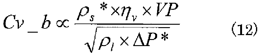
- ρs*: Compressor suction refrigerant density at predicted value Te* [kg/m3]
- ΔP*: Predicted value of high/low pressure difference at predicted value Tc* and predicted value Te* [MPa]
- The
controller 50 calculates ΔP* by converting the predicted value Tc* of the condensing temperature and the predicted value Te* of the evaporating temperature into a condensing pressure Pd and an evaporating pressure Ps using a saturation temperature. - Further, from the relationship in Expression (3), ρs* is calculated using the predicted value Te*.
- In addition, ρl is taken to be the liquid density (fixed) based on the assumption that the refrigerant at the inlet of the
expansion valve 3 is in a liquid state. Note that, ηv is assumed to be fixed (unique value). - The
controller 50 calculates the base Cv value (Cv_b) of theexpansion valve 3 by substituting these values into Expression (12). - The
controller 50 calculates the target value Tdm for the discharge temperature of the refrigerant to be discharged from the compressor 1 based on the predicted value Tc* of the condensing temperature, the predicted value Te* of the evaporating temperature, and the compressor capacity VP. - For example, a theoretical value, test data, or the like of a characteristic of the discharge temperature Td for the condensing temperature Tc, the evaporating temperature Te, and the compressor capacity VP when the degree of suction superheat of the compressor 1 is zero is stored in advance as a table in the ROM, for example. The discharge temperature Td corresponding to the predicted value Tc, the predicted value Te*, and the compressor capacity VP is set as the target value Tdm for the discharge temperature by referring to this table. In other words, as shown in
Fig. 3 , the target value Tdm for the discharge temperature is the discharge temperature Td when the degree of suction superheat of the compressor 1 is zero. - The
controller 50 determines whether or not the target value Tdm for the discharge temperature calculated in Step S209 is more than a discharge temperature maximum permitted value Tdmax. - The discharge temperature maximum permitted value Tdmax, which is a value unique to the compressor 1, is stored in advance in the ROM and the like.
- When the target value Tdm for the discharge temperature is more than the discharge temperature maximum permitted value Tdmax, the
controller 50 calculates a Cv correction value ΔCvtd based on a difference between the target value Tdm for the discharge temperature and the discharge temperature maximum permitted value Tdmax. - The Cv correction value ΔCvtd is a value greater than zero. As the difference between the target value Tdm for the discharge temperature and the discharge temperature maximum permitted value Tdmax becomes larger, the larger value is set as the Cv correction value ΔCvtd. In other words, when the target value Tdm for the discharge temperature is more than the discharge temperature maximum permitted value Tdmax, the Cv value is corrected so that the opening degree of the
expansion valve 3 increases to prevent the discharge temperature Td after startup from being equal to or more than the discharge temperature maximum permitted value Tdmax. - When the target value Tdm for the discharge temperature is not more than the discharge temperature maximum permitted value Tdmax, the
controller 50 sets the Cv correction value ΔCvtd to zero, and the processing proceeds to Step S213. - The
controller 50 calculates a base opening degree LPbase by converting a value obtained by adding the Cv correction value ΔCvtd to the base Cv value (Cv_b) of theexpansion valve 3 using a conversion function fLEV for converting the Cv value into the setting opening degree LP. - As shown in
Fig. 4 , the Cv value [-] and the setting opening degree LP [pulse] have a correspondence relationship unique to theexpansion valve 3. Such a correspondence relationship is approximated and stored in the ROM in advance as the conversion function fLEV. Note that, the correspondence relationship between the setting opening degree LP and the Cv value may also be stored as table information. - The
controller 50 then finishes the base opening degree calculation, and the processing proceeds to Step S102 (Fig. 2 ). -
Fig. 6 is a p-h diagram showing low-pressure correction control of the refrigeration cycle apparatus according to Embodiment 1 of the present invention. -
Fig. 7 is a diagram illustrating a low-pressure correction control flow of the refrigeration cycle apparatus according to Embodiment 1 of the present invention. - The above-mentioned base opening degree LPbase is an opening degree calculated based on the assumption that the refrigerant at the inlet of the
expansion valve 3 is in a liquid state. When the refrigerant at the inlet of theexpansion valve 3 is in a two-phase gas-liquid state, the refrigerant density is less than that for a liquid state. As a result, pressure loss increases, which can lead to a decrease in the refrigerant pressure on the low-pressure side (drawing-in of low-pressure). - In
Fig. 6 , the solid line represents a refrigerant circuit in which the refrigerant at the inlet of theexpansion valve 3 is in a liquid state when the pressure on the low-pressure side (predicted value Tc* and predicted value Te*) is stable. The dotted line represents a refrigerant circuit in which the refrigerant at the inlet of theexpansion valve 3 is in a two-phase gas-liquid state when the pressure on the low-pressure side has decreased. - As can be seen from above, when the current evaporating temperature Te is lower than the predicted value Te*, the
controller 50 determines that the refrigerant at the inlet of theexpansion valve 3 is in a two-phase gas-liquid state (low density) (S102), and performs low-pressure correction control. Further, thecontroller 50 also suppresses the decrease in pressure on the low-pressure side by correcting the opening degree of theexpansion valve 3 so that the condensing temperature is the predicted value Tc* and the evaporating temperature is the predicted value Te*. - A calculation example of the low-pressure correction opening degree ΔLPte is described below.
- From the relationship between Expression (10) and Expression (11), in the refrigerant circuit when the pressure on the low-pressure side is stable (predicted value Tc* and predicted value Te*), Expression (13) holds. Further, in the refrigerant circuit when the pressure on the low-pressure side has decreased (actual measured value Tc of the condensing temperature and actual measured value Te of the evaporating temperature), Expression (14) holds.
[Math. 13]
- Cvte: Corrected Cv value [-]
- ρs*: Compressor suction refrigerant density at predicted value Te* [kg/m3]
- ηv: Volumetric efficiency [-]
- VP: Compressor capacity [cc x Hz]
- ρl: Expansion valve inlet refrigerant density [kg/m3]
- ΔP*: Predicted value of high/low pressure difference at predicted value Tc* and predicted value Te* [MPa]
- Cv: Cv value before correction [-]
- ps: Compressor suction refrigerant density at actual measured value Te [kg/m3] ηv: Volumetric efficiency [-]
- VP: Compressor capacity [cc x Hz]
- ρl: Expansion valve inlet refrigerant density [kg/m3]
- ΔP: Actual measured value of pressure difference between condensing pressure Pd of condensor and evaporating pressure Ps of evaporator [MPa]
- Rearranging Expression (13) and Expression (14) gives Expression (15).
[Math. 15]
- Therefore, the low-pressure correction opening degree ΔLPte required to achieve the predicted value Tc* and the predicted value Te* is represented by Expression (16).
- [Math. 16]

- Next, the low-pressure correction control operation is described based on each of the steps of
Fig. 7 . - The
controller 50 calculates the predicted value ΔP* of the high/low pressure difference based on the predicted value Tc* of the condensing temperature and the predicted value Te* of the evaporating temperature. For example, the predicted value Tc* of the condensing temperature is converted into the condensing pressure Pd and the predicted value Te* of the evaporating temperature is converted into the evaporating pressure Ps using their respective saturation temperatures. Then, the predicted value ΔP* of the high/low pressure difference is calculated based on the difference between the condensing pressure Pd and the evaporating pressure Ps. - The
controller 50 calculates the actual measured value ΔP of the high/low pressure difference based on the difference between the discharge pressure Pd detected by thedischarge pressure sensor 42 and the suction pressure Ps detected by thesuction pressure sensor 43. Note that, the actual measured value ΔP of the high/low pressure difference may also be calculated by separately providing a temperature sensor for detecting the condensing temperature and a temperature sensor for detecting the evaporating temperature, and converting the measured temperatures into the respective pressure values. - From the relationship in Expression (3), the
controller 50 calculates ρs* using the predicted value Te*. - The
controller 50 calculates ps using the actual measured value Te of the current evaporating temperature based on the relationship in Expression (3). - The actual measured value Te of the evaporating temperature can be calculated by converting the suction pressure Ps detected by the
suction pressure sensor 43 into a refrigerant saturated gas temperature. Note that, a temperature sensor for detecting the evaporating temperature may also be separately provided. - The
controller 50 converts the current setting opening degree LP into a Cv value using the conversion function fLEVCv for converting the setting opening degree LP into a Cv value. - As shown in
Fig. 4 , the conversion function fLEVCv may be determined based on the correspondence relationship between the Cv value [-] and the setting opening degree LP [pulse], or may be stored as table information. - The
controller 50 calculates the Cvte, which is the corrected Cv value, by substituting each of the values calculated in Step S301 to Step S305 into Expression (15). - The
controller 50 calculates the difference between a value obtained by converting the Cvte into an opening degree setting value and a value obtained by converting the current Cv value into an opening degree setting value as the low-pressure correction opening degree ΔLPte. - The
controller 50 then finishes the low-pressure correction control, and the processing proceeds to Step S105 (Fig. 2 ). -
Fig. 8 is a diagram illustrating a Td correction control flow of the refrigeration cycle apparatus according to Embodiment 1 of the present invention. The control flow is described below based on each of the steps ofFig. 8 . - The
controller 50 calculates the target value Tdm for the discharge temperature of the refrigerant to be discharged from the compressor 1 based on the predicted value Tc* of the condensing temperature, the predicted value Te* of the evaporating temperature, and the compressor capacity VP. - For example, the theoretical value, test data, or the like of a characteristic of the discharge temperature Td for the condensing temperature Tc, the evaporating temperature Te, and the compressor capacity VP when the degree of suction superheat of the compressor 1 is zero is stored in advance as a table in the ROM, for example. The discharge temperature Td corresponding to the predicted value Tc, the predicted value Te*, and the compressor capacity VP is set as the target value Tdm for the discharge temperature by referring to this table. In other words, as shown in
Fig. 3 , the target value Tdm for the discharge temperature is the discharge temperature Td when the degree of suction superheat of the compressor 1 is zero. - The
controller 50 calculates the Cv correction value ΔCvtd based on the difference between the current discharge temperature Td detected by thedischarge temperature sensor 41 and the target value Tdm for the discharge temperature. - The Cv correction value ΔCvtd is a value greater than zero. As the difference between the current discharge temperature Td and the target value Tdm for the discharge temperature becomes larger, the larger value is set as the Cv correction value ΔCvtd.
- Further, when the discharge temperature Td is more than the target value Tdm, the Cv correction value ΔCvtd is set to a positive value, and when the discharge temperature Td is less than the target value Tdm, the Cv correction value ΔCvtd is set to a negative value. In other words, the discharge temperature Td is controlled to be at the target value Tdm by increasing the opening degree of the
expansion valve 3 when the actual measured value of the discharge temperature Td is more than the target value Tdm, and decreasing the opening degree of theexpansion valve 3 when the actual measured value of the discharge temperature Td is less than the target value Tdm. - The
controller 50 converts a value calculated by adding ΔCvtd to the current Cv value into an opening degree setting value and converts the current Cv value into an opening degree setting value, and calculates the difference between the opening degree setting values obtained by the conversion as the Td correction opening degree ΔLPtd. - The
controller 50 then finishes the Td correction control, and the processing proceeds to Step S107 (Fig. 2 ). -
Fig. 9 is a diagram showing examples of operation results of the refrigeration cycle apparatus according to Embodiment 1 of the present invention. - As shown in
Fig. 9 , the base opening degree of theexpansion valve 3 when the compressor 1 is started or when the compressor capacity VP is changed is a value that is proportional to the compressor capacity VP. - When the actual measured value of the current evaporating temperature Te is lower than the predicted value Te* by a predetermined temperature or more, the
controller 50 determines that the refrigerant at the inlet of theexpansion valve 3 is in a two-phase gas-liquid state (low density), and performs low-pressure correction control. As a result, the opening degree of theexpansion valve 3 is increased by the low-pressure correction opening degree ΔLPte, and the decrease in the pressure on the low-pressure side is suppressed. - When the deviation between the actual measured value Te of the evaporating temperature and the predicted value Te* has decreased, or, when the deviation between the current setting opening degree LP of the
expansion valve 3 and the base opening degree LPbase has decreased, Td correction control is performed. As a result, the discharge temperature Td is controlled to be at the target value Tdm by increasing or decreasing the opening degree of theexpansion valve 3 by the Td correction opening degree ΔLPtd. - As described above, in Embodiment 1, when starting the compressor 1 or when changing the operating capacity of the compressor 1, the
controller 50 calculates the predicted value Tc* of the condensing temperature of the refrigerant and the predicted value Te* of the evaporating temperature of the refrigerant after the compressor 1 is started or after the operating capacity of the compressor 1 is changed based on the condensor suction air temperature Tac, the evaporator suction air temperature Tae, and the compressor capacity VP. Further, thecontroller 50 determines the opening degree to be set for theexpansion valve 3 based on the predicted value Tc* of the condensing temperature, the predicted value Te* of the evaporating temperature, and the compressor capacity VP. - Consequently, the appropriate opening degree of the
expansion valve 3 can be set based on the environmental conditions and the compressor capacity VP. As a result, liquid can be prevented from flowing back into the compressor 1, allowing device reliability to be improved. Further, the predicted value Tc* and the predicted value Te* after the compressor 1 is started or after the operating capacity of the compressor 1 is changed are calculated, and hence the quick response of the opening degree control of theexpansion valve 3 can be improved. - In addition, in Embodiment 1, the predicted value ΔP* of the pressure difference between the condensing pressure and the evaporating pressure is calculated based on the predicted value Tc* and the predicted value Te*, and the actual measured value ΔP of the pressure difference between the condensing pressure and the evaporating pressure is calculated based on the condensor suction air temperature Tac and the evaporator suction air temperature Tae. Then, the opening degree to be set for the
expansion valve 3 is corrected by calculating the low-pressure correction opening degree ΔLPte based on the predicted value ΔP* of the pressure difference and the actual measured value ΔP of the pressure difference. - As a result, the decrease in the refrigerant pressure on the low-pressure side (drawing-in of low-pressure) that occurs under an environmental condition in which the outside air temperature is low can be suppressed. Further, suppressing the decrease in the refrigerant pressure on the low-pressure side enables the refrigerant circuit amount to be increased, and hence the heating capacity to be improved. In addition, suppressing the drawing-in of low pressure during startup at a low outside air temperature enables deterioration in the operating efficiency to be suppressed, and hence enables energy savings to be improved.
- Further, in Embodiment 1, the
controller 50 calculates the target value Tdm for the discharge temperature of the refrigerant to be discharged from the compressor 1 after the operating capacity of the compressor 1 is changed based on the predicted value Tc*, the predicted value Te*, and the compressor capacity VP. In addition, thecontroller 50 calculates the Td correction opening degree ΔLPtd, and corrects the opening degree to be set for theexpansion valve 3 based on the difference between the actual measured value of the discharge temperature Td and the target value Tdm. - As a result, an excessive increase in the discharge temperature at the compressor 1 can be suppressed, and highly efficient operation can be realized within the permitted operating range of the compressor 1, allowing device reliability to be improved.
- Further, in Embodiment 1, when the target value Tdm for the discharge temperature is more than the discharge temperature maximum permitted value Tdmax, the
controller 50 corrects the opening degree to be set for theexpansion valve 3 based on the difference between the discharge temperature maximum permitted value Tdmax and the target value Tdm. - As a result, when the target value Tdm for the discharge temperature calculated using the predicted value Te* and the predicted value Tc* is a higher temperature than that of the permitted operating range of the compressor 1, by making correction in advance so that the opening degree of the
expansion valve 3 is increased, the startup operation can be performed within the permitted operating range because of a wet suction operation of the compressor 1. - Note that, in the embodiment described above, the base opening degree calculation (S101), low-pressure correction control (S103), and Td correction control (S106) are performed as the control operation for setting the opening degree of the
expansion valve 3. However, the present invention is not limited to this embodiment. The control may be performed by executing an arbitrary one or two of the base opening degree calculation, low-pressure correction control, and Td correction control. - For example, in
Fig. 2 , the opening degree of theexpansion valve 3 may be set by omitting Step S102 to Step S104, and just calculating the base opening degree and performing the Td correction control. Further, for example, inFig. 2 , the opening degree of theexpansion valve 3 may be set by omitting Step S105 and Step S106, and just calculating the base opening degree and performing the low-pressure correction control. Still further, for example, inFig. 2 , the opening degree of theexpansion valve 3 may be set by omitting Step S102 to Step S107, and just calculating the base opening degree. Still even further, for example, inFig. 2 , the opening degree of theexpansion valve 3 may be corrected by omitting Step S101, setting the base opening degree to an arbitrary opening degree, and then performing the low-pressure correction control and the low-pressure correction control. - 1
compressor 2outdoor heat exchanger 3 expansion valve 5liquid pipe 6indoor heat exchanger 7gas pipe 8 four-way valve 20refrigerant circuit 31outdoor fan 32indoor fan 41discharge temperature sensor 42discharge pressure sensor 43suction pressure sensor 44outdoor temperature sensor 45indoor temperature sensor 50controller 61outdoor unit 62indoor unit 100 refrigeration cycle apparatus

Claims (6)
- A refrigeration cycle apparatus for circulating refrigerant through a circuit in which a compressor having a changeable operating capacity, a condensor, an expansion valve having a changeable opening degree, and an evaporator are connected to each other by pipes, the refrigeration cycle apparatus comprising:a first temperature sensor for detecting a temperature of a heat medium to be subjected to heat exchange with the refrigerant in the condensor;a second temperature sensor for detecting a temperature of a heat medium to be subjected to heat exchange with the refrigerant in the evaporator; anda controller for controlling the operating capacity of the compressor and the opening degree of the expansion valve,the controller being configured to, when starting the compressor or when changing the operating capacity of the compressorcalculate a predicted value (Tc*) of a condensing temperature of the refrigerant and a predicted value (Te*) of an evaporating temperature of the refrigerant being predicted after the compressor is started or after the operating capacity of the compressor is changed, based on a detection value of the first temperature sensor, a detection value of the second temperature sensor, and a setting value (VP) of the operating capacity to be set for the compressor anddetermine the opening degree to be set for the expansion valve based on the predicted value (Tc*) of the condensing temperature, the predicted value (Te*) of the evaporating temperature, and the setting value (VP) of the operating capacity to be set for the compressor.
- The refrigeration cycle apparatus of claim 1, wherein the controller is configured to
calculate a predicted value (ΔP*) of a pressure difference between a condensing pressure of the condensor and an evaporating pressure of the evaporator based on the predicted value (Tc*) of the condensing temperature and the predicted value (Te*) of the evaporating temperature and
correct the opening degree to be set for the expansion valve based on an actual measured value (ΔP) of the pressure difference between the condensing pressure of the condensor and the evaporating pressure of the evaporator and on the predicted value (ΔP*) of the pressure difference. - The refrigeration cycle apparatus of claim 1 or 2, further comprising a third temperature sensor for detecting a discharge temperature of the refrigerant discharged from the compressor,
wherein the controller is configured tocalculate a target value (Tdm) for the discharge temperature of the refrigerant to be discharged from the compressor based on the predicted value (Tc*) of the condensing temperature, the predicted value (Te*) of the evaporating temperature, and the setting value (VP) of the operating capacity to be set for the compressor andcorrect the opening degree to be set for the expansion valve based on a difference between a detection value of the third temperature sensor and the target value (Tdm) for the discharge temperature. - The refrigeration cycle apparatus of any one of claims 1 to 3, wherein the controller is configured to
calculate a target value (Tdm) for a discharge temperature of the refrigerant to be discharged from the compressor based on the predicted value (Tc*) of the condensing temperature, the predicted value (Te*) of the evaporating temperature, and the setting value (VP) of the operating capacity to be set for the compressor and
correct, when the target value (Tdm) for the discharge temperature is more than a maximum value set in advance, the opening degree to be set for the expansion valve based on a difference between the maximum value and the target value (Tdm) for the discharge temperature. - The refrigeration cycle apparatus of any one of claims 1 to 4, wherein the refrigerant has a higher ratio of specific heat than R410A.
- A method of controlling a refrigeration cycle apparatus for circulating refrigerant through a circuit in which a compressor having a changeable operating capacity, a condensor, an expansion valve having a changeable opening degree, and an evaporator are connected to each other by pipes, the method comprising, when the compressor is started or when the operating capacity of the compressor is changed:a step of acquiring a setting value (VP) of the operating capacity to be set for the compressor;a first temperature detection step of detecting a temperature of a heat medium to be subjected to heat exchange with the refrigerant in the condensor;a second temperature detection step of detecting a temperature of a heat medium to be subjected to heat exchange with the refrigerant in the evaporator;a step of calculating a predicted value (Tc*) of a condensing temperature of the refrigerant and a predicted value (Te*) of an evaporating temperature of the refrigerant being predicted after the compressor is started or after the operating capacity of the compressor is changed, based on a detection value acquired in the first temperature detection step, a detection value acquired in the second temperature detection step, and the setting value (VP) of the operating capacity to be set for the compressor; anda step of determining the opening degree to be set for the expansion valve based on the predicted value (Tc*) of the condensing temperature, the predicted value (Te*) of the evaporating temperature, and the setting value (VP) of the operating capacity to be set for the compressor.
Applications Claiming Priority (1)
| Application Number | Priority Date | Filing Date | Title |
|---|---|---|---|
| PCT/JP2013/052241 WO2014118952A1 (en) | 2013-01-31 | 2013-01-31 | Refrigeration-cycle device and method for controlling refrigeration-cycle device |
Publications (3)
| Publication Number | Publication Date |
|---|---|
| EP2952829A1 true EP2952829A1 (en) | 2015-12-09 |
| EP2952829A4 EP2952829A4 (en) | 2016-12-21 |
| EP2952829B1 EP2952829B1 (en) | 2020-09-09 |
Family
ID=51261697
Family Applications (1)
| Application Number | Title | Priority Date | Filing Date |
|---|---|---|---|
| EP13873980.0A Not-in-force EP2952829B1 (en) | 2013-01-31 | 2013-01-31 | Refrigeration-cycle device and method for controlling refrigeration-cycle device |
Country Status (5)
| Country | Link |
|---|---|
| US (1) | US20150362238A1 (en) |
| EP (1) | EP2952829B1 (en) |
| JP (1) | JP6109205B2 (en) |
| CN (1) | CN104969014B (en) |
| WO (1) | WO2014118952A1 (en) |
Cited By (1)
| Publication number | Priority date | Publication date | Assignee | Title |
|---|---|---|---|---|
| WO2017143267A1 (en) | 2016-02-18 | 2017-08-24 | Emerson Climate Technologies, Inc. | Compressor floodback protection system |
Families Citing this family (14)
| Publication number | Priority date | Publication date | Assignee | Title |
|---|---|---|---|---|
| WO2014115891A1 (en) * | 2013-01-28 | 2014-07-31 | ダイキン工業 株式会社 | Air conditioner |
| JP6242321B2 (en) * | 2014-10-03 | 2017-12-06 | 三菱電機株式会社 | Air conditioner |
| BR112018015885B1 (en) * | 2016-02-04 | 2023-04-04 | Franke Technology And Trademark Ltd | REFRIGERATION APPLIANCE |
| DE102016005782B4 (en) * | 2016-05-11 | 2018-10-18 | Audi Ag | Method for operating a vehicle air conditioning system with a refrigerant circuit |
| CN107752587A (en) * | 2016-08-16 | 2018-03-06 | 开利公司 | Refrigerated display case, refrigeration system and constant-temperature control method |
| US11060771B2 (en) * | 2016-10-25 | 2021-07-13 | Samsung Electronics Co., Ltd. | Air conditioner with a refrigerant ratio adjustor |
| CN106556187B (en) * | 2016-11-10 | 2019-02-19 | 华为技术有限公司 | Control method, device and system for operation of air-conditioning refrigeration system in critical state |
| CN111356885B (en) * | 2017-11-22 | 2022-02-01 | 三菱电机株式会社 | Air conditioner |
| EP3892940B1 (en) * | 2018-12-06 | 2022-09-07 | Mitsubishi Electric Corporation | Refrigeration cycle device |
| CN112413942B (en) * | 2020-11-24 | 2024-09-24 | 珠海格力电器股份有限公司 | Air conditioning system and control method thereof |
| JP7499880B2 (en) * | 2020-12-11 | 2024-06-14 | 三菱電機株式会社 | Learning device and inference device for the state of an air conditioning system |
| CN114608263A (en) * | 2022-03-11 | 2022-06-10 | 长虹美菱股份有限公司 | Quick-freezing control method of refrigerator refrigerating system based on electronic expansion valve |
| CN118306166A (en) * | 2023-01-09 | 2024-07-09 | 开利公司 | Multi-temperature zone air conditioning system and control method thereof, and transport refrigeration vehicle |
| JP7779354B1 (en) * | 2024-08-29 | 2025-12-03 | 株式会社富士通ゼネラル | Refrigeration cycle equipment |
Family Cites Families (21)
| Publication number | Priority date | Publication date | Assignee | Title |
|---|---|---|---|---|
| US3276245A (en) * | 1963-04-22 | 1966-10-04 | Waste King Corp | Density compensator device |
| JPS59145451A (en) * | 1983-02-08 | 1984-08-20 | 三菱電機株式会社 | Refrigeration cycle device |
| JPH0830625B2 (en) * | 1986-12-08 | 1996-03-27 | 松下冷機株式会社 | Air conditioner |
| JP2921254B2 (en) * | 1992-03-24 | 1999-07-19 | ダイキン工業株式会社 | Refrigeration equipment |
| JP3208923B2 (en) | 1993-05-28 | 2001-09-17 | ダイキン工業株式会社 | Operation control device for air conditioner |
| JP3483711B2 (en) * | 1996-07-25 | 2004-01-06 | 株式会社エヌ・ティ・ティ ファシリティーズ | Air conditioner and its control method |
| JPH11153366A (en) | 1997-11-25 | 1999-06-08 | Daikin Ind Ltd | Start-up control device for refrigeration equipment |
| KR100332764B1 (en) | 1999-05-27 | 2002-04-17 | 구자홍 | Start-up algorithm for inverter driving heat pump |
| JP2001304699A (en) * | 2000-04-26 | 2001-10-31 | Daikin Ind Ltd | Refrigeration equipment |
| JP3661014B2 (en) * | 2001-09-28 | 2005-06-15 | ダイキン工業株式会社 | Refrigeration equipment |
| JP4984453B2 (en) * | 2004-09-22 | 2012-07-25 | 株式会社デンソー | Ejector refrigeration cycle |
| JP3943104B2 (en) * | 2004-10-12 | 2007-07-11 | 三菱電機株式会社 | Multi-room air conditioner |
| CA2616286A1 (en) * | 2005-08-31 | 2007-03-08 | Carrier Corporation | Heat pump water heating system using variable speed compressor |
| JP4626630B2 (en) * | 2007-05-24 | 2011-02-09 | トヨタ自動車株式会社 | Feedback control system |
| JP5106536B2 (en) * | 2007-08-28 | 2012-12-26 | 三菱電機株式会社 | Air conditioner |
| US8459053B2 (en) * | 2007-10-08 | 2013-06-11 | Emerson Climate Technologies, Inc. | Variable speed compressor protection system and method |
| JP5022920B2 (en) | 2008-01-16 | 2012-09-12 | 三洋電機株式会社 | Air conditioner |
| JP5326488B2 (en) * | 2008-02-29 | 2013-10-30 | ダイキン工業株式会社 | Air conditioner |
| JP2010175106A (en) * | 2009-01-28 | 2010-08-12 | Sanyo Electric Co Ltd | Refrigerating apparatus |
| JP2012127631A (en) * | 2010-12-17 | 2012-07-05 | Daikin Industries Ltd | Electric-operated valve control device |
| JP5316665B2 (en) * | 2012-03-30 | 2013-10-16 | 富士通株式会社 | Fan device |
-
2013
- 2013-01-31 EP EP13873980.0A patent/EP2952829B1/en not_active Not-in-force
- 2013-01-31 JP JP2014559444A patent/JP6109205B2/en not_active Expired - Fee Related
- 2013-01-31 WO PCT/JP2013/052241 patent/WO2014118952A1/en not_active Ceased
- 2013-01-31 CN CN201380071974.2A patent/CN104969014B/en not_active Expired - Fee Related
- 2013-01-31 US US14/764,312 patent/US20150362238A1/en not_active Abandoned
Cited By (4)
| Publication number | Priority date | Publication date | Assignee | Title |
|---|---|---|---|---|
| WO2017143267A1 (en) | 2016-02-18 | 2017-08-24 | Emerson Climate Technologies, Inc. | Compressor floodback protection system |
| EP3417219A4 (en) * | 2016-02-18 | 2019-11-06 | Emerson Climate Technologies, Inc. | Compressor floodback protection system |
| US10801762B2 (en) | 2016-02-18 | 2020-10-13 | Emerson Climate Technologies, Inc. | Compressor floodback protection system |
| US11573037B2 (en) | 2016-02-18 | 2023-02-07 | Emerson Climate Technologies, Inc. | Compressor floodback protection system |
Also Published As
| Publication number | Publication date |
|---|---|
| EP2952829B1 (en) | 2020-09-09 |
| JPWO2014118952A1 (en) | 2017-01-26 |
| EP2952829A4 (en) | 2016-12-21 |
| CN104969014B (en) | 2017-04-05 |
| JP6109205B2 (en) | 2017-04-05 |
| WO2014118952A1 (en) | 2014-08-07 |
| CN104969014A (en) | 2015-10-07 |
| US20150362238A1 (en) | 2015-12-17 |
Similar Documents
| Publication | Publication Date | Title |
|---|---|---|
| EP2952829B1 (en) | Refrigeration-cycle device and method for controlling refrigeration-cycle device | |
| EP3889523B1 (en) | Refrigerant leakage determination system and refrigeration cycle device | |
| EP2320169B1 (en) | Air conditioner and method for determining the amount of refrigerant therein | |
| US10323862B2 (en) | Air conditioning unit having dynamic target condensing and evaporating values based on load requirements | |
| EP3859247B1 (en) | Air-conditioning device | |
| EP2163839B1 (en) | Air conditioner | |
| AU2016202855B2 (en) | Refrigeration apparatus | |
| EP3587948B1 (en) | Air conditioner | |
| EP2211123B1 (en) | Air conditioner | |
| EP2314958A1 (en) | Method for judging amount of refrigerant of air conditioner and air conditioner | |
| EP3657090B1 (en) | Air conditioning system | |
| EP2623891B1 (en) | Outdoor unit for refrigeration device | |
| EP2270405A1 (en) | Refrigerating device | |
| EP1983280A1 (en) | Air conditioner | |
| EP2730863B1 (en) | Refrigeration and air conditioning device and method for controlling refrigeration and air conditioning device | |
| WO2005121664A1 (en) | Air conditioner | |
| KR20110104054A (en) | Load Handling Balance Setting Device | |
| JP2017075760A (en) | Air conditioner | |
| EP3647688A1 (en) | Air-conditioning device | |
| US9851134B2 (en) | Air-conditioning apparatus | |
| JPWO2017094172A1 (en) | Air conditioner | |
| EP3165846B1 (en) | Refrigerating and air-conditioning apparatus | |
| JP6415612B2 (en) | Refrigeration cycle equipment | |
| EP3974744A1 (en) | Air conditioning device | |
| CN119665345B (en) | Heat pump air conditioning system |
Legal Events
| Date | Code | Title | Description |
|---|---|---|---|
| PUAI | Public reference made under article 153(3) epc to a published international application that has entered the european phase |
Free format text: ORIGINAL CODE: 0009012 |
|
| 17P | Request for examination filed |
Effective date: 20150730 |
|
| AK | Designated contracting states |
Kind code of ref document: A1 Designated state(s): AL AT BE BG CH CY CZ DE DK EE ES FI FR GB GR HR HU IE IS IT LI LT LU LV MC MK MT NL NO PL PT RO RS SE SI SK SM TR |
|
| AX | Request for extension of the european patent |
Extension state: BA ME |
|
| DAX | Request for extension of the european patent (deleted) | ||
| A4 | Supplementary search report drawn up and despatched |
Effective date: 20161122 |
|
| RIC1 | Information provided on ipc code assigned before grant |
Ipc: F25B 1/00 20060101AFI20161116BHEP Ipc: F25B 49/02 20060101ALI20161116BHEP Ipc: F25B 13/00 20060101ALI20161116BHEP |
|
| GRAP | Despatch of communication of intention to grant a patent |
Free format text: ORIGINAL CODE: EPIDOSNIGR1 |
|
| STAA | Information on the status of an ep patent application or granted ep patent |
Free format text: STATUS: GRANT OF PATENT IS INTENDED |
|
| INTG | Intention to grant announced |
Effective date: 20200504 |
|
| GRAS | Grant fee paid |
Free format text: ORIGINAL CODE: EPIDOSNIGR3 |
|
| GRAA | (expected) grant |
Free format text: ORIGINAL CODE: 0009210 |
|
| STAA | Information on the status of an ep patent application or granted ep patent |
Free format text: STATUS: THE PATENT HAS BEEN GRANTED |
|
| AK | Designated contracting states |
Kind code of ref document: B1 Designated state(s): AL AT BE BG CH CY CZ DE DK EE ES FI FR GB GR HR HU IE IS IT LI LT LU LV MC MK MT NL NO PL PT RO RS SE SI SK SM TR |
|
| REG | Reference to a national code |
Ref country code: GB Ref legal event code: FG4D |
|
| REG | Reference to a national code |
Ref country code: AT Ref legal event code: REF Ref document number: 1312065 Country of ref document: AT Kind code of ref document: T Effective date: 20200915 Ref country code: CH Ref legal event code: EP |
|
| REG | Reference to a national code |
Ref country code: DE Ref legal event code: R096 Ref document number: 602013072472 Country of ref document: DE |
|
| REG | Reference to a national code |
Ref country code: IE Ref legal event code: FG4D |
|
| REG | Reference to a national code |
Ref country code: LT Ref legal event code: MG4D |
|
| PG25 | Lapsed in a contracting state [announced via postgrant information from national office to epo] |
Ref country code: SE Free format text: LAPSE BECAUSE OF FAILURE TO SUBMIT A TRANSLATION OF THE DESCRIPTION OR TO PAY THE FEE WITHIN THE PRESCRIBED TIME-LIMIT Effective date: 20200909 Ref country code: NO Free format text: LAPSE BECAUSE OF FAILURE TO SUBMIT A TRANSLATION OF THE DESCRIPTION OR TO PAY THE FEE WITHIN THE PRESCRIBED TIME-LIMIT Effective date: 20201209 Ref country code: BG Free format text: LAPSE BECAUSE OF FAILURE TO SUBMIT A TRANSLATION OF THE DESCRIPTION OR TO PAY THE FEE WITHIN THE PRESCRIBED TIME-LIMIT Effective date: 20201209 Ref country code: HR Free format text: LAPSE BECAUSE OF FAILURE TO SUBMIT A TRANSLATION OF THE DESCRIPTION OR TO PAY THE FEE WITHIN THE PRESCRIBED TIME-LIMIT Effective date: 20200909 Ref country code: LT Free format text: LAPSE BECAUSE OF FAILURE TO SUBMIT A TRANSLATION OF THE DESCRIPTION OR TO PAY THE FEE WITHIN THE PRESCRIBED TIME-LIMIT Effective date: 20200909 Ref country code: FI Free format text: LAPSE BECAUSE OF FAILURE TO SUBMIT A TRANSLATION OF THE DESCRIPTION OR TO PAY THE FEE WITHIN THE PRESCRIBED TIME-LIMIT Effective date: 20200909 Ref country code: GR Free format text: LAPSE BECAUSE OF FAILURE TO SUBMIT A TRANSLATION OF THE DESCRIPTION OR TO PAY THE FEE WITHIN THE PRESCRIBED TIME-LIMIT Effective date: 20201210 |
|
| REG | Reference to a national code |
Ref country code: AT Ref legal event code: MK05 Ref document number: 1312065 Country of ref document: AT Kind code of ref document: T Effective date: 20200909 |
|
| REG | Reference to a national code |
Ref country code: NL Ref legal event code: MP Effective date: 20200909 |
|
| PG25 | Lapsed in a contracting state [announced via postgrant information from national office to epo] |
Ref country code: LV Free format text: LAPSE BECAUSE OF FAILURE TO SUBMIT A TRANSLATION OF THE DESCRIPTION OR TO PAY THE FEE WITHIN THE PRESCRIBED TIME-LIMIT Effective date: 20200909 Ref country code: PL Free format text: LAPSE BECAUSE OF FAILURE TO SUBMIT A TRANSLATION OF THE DESCRIPTION OR TO PAY THE FEE WITHIN THE PRESCRIBED TIME-LIMIT Effective date: 20200909 Ref country code: RS Free format text: LAPSE BECAUSE OF FAILURE TO SUBMIT A TRANSLATION OF THE DESCRIPTION OR TO PAY THE FEE WITHIN THE PRESCRIBED TIME-LIMIT Effective date: 20200909 |
|
| PG25 | Lapsed in a contracting state [announced via postgrant information from national office to epo] |
Ref country code: CZ Free format text: LAPSE BECAUSE OF FAILURE TO SUBMIT A TRANSLATION OF THE DESCRIPTION OR TO PAY THE FEE WITHIN THE PRESCRIBED TIME-LIMIT Effective date: 20200909 Ref country code: EE Free format text: LAPSE BECAUSE OF FAILURE TO SUBMIT A TRANSLATION OF THE DESCRIPTION OR TO PAY THE FEE WITHIN THE PRESCRIBED TIME-LIMIT Effective date: 20200909 Ref country code: RO Free format text: LAPSE BECAUSE OF FAILURE TO SUBMIT A TRANSLATION OF THE DESCRIPTION OR TO PAY THE FEE WITHIN THE PRESCRIBED TIME-LIMIT Effective date: 20200909 Ref country code: SM Free format text: LAPSE BECAUSE OF FAILURE TO SUBMIT A TRANSLATION OF THE DESCRIPTION OR TO PAY THE FEE WITHIN THE PRESCRIBED TIME-LIMIT Effective date: 20200909 Ref country code: PT Free format text: LAPSE BECAUSE OF FAILURE TO SUBMIT A TRANSLATION OF THE DESCRIPTION OR TO PAY THE FEE WITHIN THE PRESCRIBED TIME-LIMIT Effective date: 20210111 Ref country code: NL Free format text: LAPSE BECAUSE OF FAILURE TO SUBMIT A TRANSLATION OF THE DESCRIPTION OR TO PAY THE FEE WITHIN THE PRESCRIBED TIME-LIMIT Effective date: 20200909 |
|
| PG25 | Lapsed in a contracting state [announced via postgrant information from national office to epo] |
Ref country code: ES Free format text: LAPSE BECAUSE OF FAILURE TO SUBMIT A TRANSLATION OF THE DESCRIPTION OR TO PAY THE FEE WITHIN THE PRESCRIBED TIME-LIMIT Effective date: 20200909 Ref country code: AT Free format text: LAPSE BECAUSE OF FAILURE TO SUBMIT A TRANSLATION OF THE DESCRIPTION OR TO PAY THE FEE WITHIN THE PRESCRIBED TIME-LIMIT Effective date: 20200909 Ref country code: AL Free format text: LAPSE BECAUSE OF FAILURE TO SUBMIT A TRANSLATION OF THE DESCRIPTION OR TO PAY THE FEE WITHIN THE PRESCRIBED TIME-LIMIT Effective date: 20200909 Ref country code: IS Free format text: LAPSE BECAUSE OF FAILURE TO SUBMIT A TRANSLATION OF THE DESCRIPTION OR TO PAY THE FEE WITHIN THE PRESCRIBED TIME-LIMIT Effective date: 20210109 |
|
| REG | Reference to a national code |
Ref country code: DE Ref legal event code: R097 Ref document number: 602013072472 Country of ref document: DE |
|
| PG25 | Lapsed in a contracting state [announced via postgrant information from national office to epo] |
Ref country code: SK Free format text: LAPSE BECAUSE OF FAILURE TO SUBMIT A TRANSLATION OF THE DESCRIPTION OR TO PAY THE FEE WITHIN THE PRESCRIBED TIME-LIMIT Effective date: 20200909 |
|
| PLBE | No opposition filed within time limit |
Free format text: ORIGINAL CODE: 0009261 |
|
| STAA | Information on the status of an ep patent application or granted ep patent |
Free format text: STATUS: NO OPPOSITION FILED WITHIN TIME LIMIT |
|
| REG | Reference to a national code |
Ref country code: DE Ref legal event code: R119 Ref document number: 602013072472 Country of ref document: DE |
|
| 26N | No opposition filed |
Effective date: 20210610 |
|
| PG25 | Lapsed in a contracting state [announced via postgrant information from national office to epo] |
Ref country code: SI Free format text: LAPSE BECAUSE OF FAILURE TO SUBMIT A TRANSLATION OF THE DESCRIPTION OR TO PAY THE FEE WITHIN THE PRESCRIBED TIME-LIMIT Effective date: 20200909 Ref country code: DK Free format text: LAPSE BECAUSE OF FAILURE TO SUBMIT A TRANSLATION OF THE DESCRIPTION OR TO PAY THE FEE WITHIN THE PRESCRIBED TIME-LIMIT Effective date: 20200909 Ref country code: MC Free format text: LAPSE BECAUSE OF FAILURE TO SUBMIT A TRANSLATION OF THE DESCRIPTION OR TO PAY THE FEE WITHIN THE PRESCRIBED TIME-LIMIT Effective date: 20200909 |
|
| REG | Reference to a national code |
Ref country code: CH Ref legal event code: PL |
|
| PG25 | Lapsed in a contracting state [announced via postgrant information from national office to epo] |
Ref country code: LU Free format text: LAPSE BECAUSE OF NON-PAYMENT OF DUE FEES Effective date: 20210131 |
|
| REG | Reference to a national code |
Ref country code: BE Ref legal event code: MM Effective date: 20210131 |
|
| PG25 | Lapsed in a contracting state [announced via postgrant information from national office to epo] |
Ref country code: CH Free format text: LAPSE BECAUSE OF NON-PAYMENT OF DUE FEES Effective date: 20210131 Ref country code: DE Free format text: LAPSE BECAUSE OF NON-PAYMENT OF DUE FEES Effective date: 20210803 Ref country code: LI Free format text: LAPSE BECAUSE OF NON-PAYMENT OF DUE FEES Effective date: 20210131 |
|
| PG25 | Lapsed in a contracting state [announced via postgrant information from national office to epo] |
Ref country code: IE Free format text: LAPSE BECAUSE OF NON-PAYMENT OF DUE FEES Effective date: 20210131 |
|
| PG25 | Lapsed in a contracting state [announced via postgrant information from national office to epo] |
Ref country code: BE Free format text: LAPSE BECAUSE OF NON-PAYMENT OF DUE FEES Effective date: 20210131 |
|
| PG25 | Lapsed in a contracting state [announced via postgrant information from national office to epo] |
Ref country code: HU Free format text: LAPSE BECAUSE OF FAILURE TO SUBMIT A TRANSLATION OF THE DESCRIPTION OR TO PAY THE FEE WITHIN THE PRESCRIBED TIME-LIMIT; INVALID AB INITIO Effective date: 20130131 |
|
| P01 | Opt-out of the competence of the unified patent court (upc) registered |
Effective date: 20230512 |
|
| PG25 | Lapsed in a contracting state [announced via postgrant information from national office to epo] |
Ref country code: CY Free format text: LAPSE BECAUSE OF FAILURE TO SUBMIT A TRANSLATION OF THE DESCRIPTION OR TO PAY THE FEE WITHIN THE PRESCRIBED TIME-LIMIT Effective date: 20200909 |
|
| PGFP | Annual fee paid to national office [announced via postgrant information from national office to epo] |
Ref country code: GB Payment date: 20231207 Year of fee payment: 12 |
|
| PGFP | Annual fee paid to national office [announced via postgrant information from national office to epo] |
Ref country code: FR Payment date: 20231212 Year of fee payment: 12 |
|
| REG | Reference to a national code |
Ref country code: GB Ref legal event code: 746 Effective date: 20240327 |
|
| PG25 | Lapsed in a contracting state [announced via postgrant information from national office to epo] |
Ref country code: MK Free format text: LAPSE BECAUSE OF FAILURE TO SUBMIT A TRANSLATION OF THE DESCRIPTION OR TO PAY THE FEE WITHIN THE PRESCRIBED TIME-LIMIT Effective date: 20200909 |
|
| PGFP | Annual fee paid to national office [announced via postgrant information from national office to epo] |
Ref country code: IT Payment date: 20231212 Year of fee payment: 12 |
|
| PG25 | Lapsed in a contracting state [announced via postgrant information from national office to epo] |
Ref country code: TR Free format text: LAPSE BECAUSE OF FAILURE TO SUBMIT A TRANSLATION OF THE DESCRIPTION OR TO PAY THE FEE WITHIN THE PRESCRIBED TIME-LIMIT Effective date: 20200909 |
|
| PG25 | Lapsed in a contracting state [announced via postgrant information from national office to epo] |
Ref country code: MT Free format text: LAPSE BECAUSE OF FAILURE TO SUBMIT A TRANSLATION OF THE DESCRIPTION OR TO PAY THE FEE WITHIN THE PRESCRIBED TIME-LIMIT Effective date: 20200909 |
|
| GBPC | Gb: european patent ceased through non-payment of renewal fee |
Effective date: 20250131 |
|
| PG25 | Lapsed in a contracting state [announced via postgrant information from national office to epo] |
Ref country code: GB Free format text: LAPSE BECAUSE OF NON-PAYMENT OF DUE FEES Effective date: 20250131 |
|
| PG25 | Lapsed in a contracting state [announced via postgrant information from national office to epo] |
Ref country code: FR Free format text: LAPSE BECAUSE OF NON-PAYMENT OF DUE FEES Effective date: 20250131 |
|
| PG25 | Lapsed in a contracting state [announced via postgrant information from national office to epo] |
Ref country code: IT Free format text: LAPSE BECAUSE OF NON-PAYMENT OF DUE FEES Effective date: 20250131 |