EP2953009A1 - Appareil portatif et procede de controle d'un appareil de peage routier - Google Patents
Appareil portatif et procede de controle d'un appareil de peage routier Download PDFInfo
- Publication number
- EP2953009A1 EP2953009A1 EP15170260.2A EP15170260A EP2953009A1 EP 2953009 A1 EP2953009 A1 EP 2953009A1 EP 15170260 A EP15170260 A EP 15170260A EP 2953009 A1 EP2953009 A1 EP 2953009A1
- Authority
- EP
- European Patent Office
- Prior art keywords
- toll collection
- vehicle
- collection device
- handset
- transmitting
- Prior art date
- Legal status (The legal status is an assumption and is not a legal conclusion. Google has not performed a legal analysis and makes no representation as to the accuracy of the status listed.)
- Granted
Links
Images


Classifications
-
- G—PHYSICS
- G07—CHECKING-DEVICES
- G07B—TICKET-ISSUING APPARATUS; FARE-REGISTERING APPARATUS; FRANKING APPARATUS
- G07B15/00—Arrangements or apparatus for collecting fares, tolls or entrance fees at one or more control points
- G07B15/06—Arrangements for road pricing or congestion charging of vehicles or vehicle users, e.g. automatic toll systems
-
- G—PHYSICS
- G07—CHECKING-DEVICES
- G07B—TICKET-ISSUING APPARATUS; FARE-REGISTERING APPARATUS; FRANKING APPARATUS
- G07B15/00—Arrangements or apparatus for collecting fares, tolls or entrance fees at one or more control points
- G07B15/06—Arrangements for road pricing or congestion charging of vehicles or vehicle users, e.g. automatic toll systems
- G07B15/063—Arrangements for road pricing or congestion charging of vehicles or vehicle users, e.g. automatic toll systems using wireless information transmission between the vehicle and a fixed station
-
- G—PHYSICS
- G06—COMPUTING OR CALCULATING; COUNTING
- G06F—ELECTRIC DIGITAL DATA PROCESSING
- G06F1/00—Details not covered by groups G06F3/00 - G06F13/00 and G06F21/00
- G06F1/16—Constructional details or arrangements
- G06F1/1613—Constructional details or arrangements for portable computers
- G06F1/1633—Constructional details or arrangements of portable computers not specific to the type of enclosures covered by groups G06F1/1615 - G06F1/1626
- G06F1/1684—Constructional details or arrangements related to integrated I/O peripherals not covered by groups G06F1/1635 - G06F1/1675
- G06F1/1686—Constructional details or arrangements related to integrated I/O peripherals not covered by groups G06F1/1635 - G06F1/1675 the I/O peripheral being an integrated camera
-
- G—PHYSICS
- G06—COMPUTING OR CALCULATING; COUNTING
- G06V—IMAGE OR VIDEO RECOGNITION OR UNDERSTANDING
- G06V10/00—Arrangements for image or video recognition or understanding
- G06V10/20—Image preprocessing
- G06V10/22—Image preprocessing by selection of a specific region containing or referencing a pattern; Locating or processing of specific regions to guide the detection or recognition
-
- G—PHYSICS
- G08—SIGNALLING
- G08G—TRAFFIC CONTROL SYSTEMS
- G08G1/00—Traffic control systems for road vehicles
- G08G1/01—Detecting movement of traffic to be counted or controlled
- G08G1/017—Detecting movement of traffic to be counted or controlled identifying vehicles
- G08G1/0175—Detecting movement of traffic to be counted or controlled identifying vehicles by photographing vehicles, e.g. when violating traffic rules
-
- H—ELECTRICITY
- H04—ELECTRIC COMMUNICATION TECHNIQUE
- H04N—PICTORIAL COMMUNICATION, e.g. TELEVISION
- H04N2201/00—Indexing scheme relating to scanning, transmission or reproduction of documents or the like, and to details thereof
- H04N2201/32—Circuits or arrangements for control or supervision between transmitter and receiver or between image input and image output device, e.g. between a still-image camera and its memory or between a still-image camera and a printer device
- H04N2201/3201—Display, printing, storage or transmission of additional information, e.g. ID code, date and time or title
- H04N2201/3225—Display, printing, storage or transmission of additional information, e.g. ID code, date and time or title of data relating to an image, a page or a document
- H04N2201/3226—Display, printing, storage or transmission of additional information, e.g. ID code, date and time or title of data relating to an image, a page or a document of identification information or the like, e.g. ID code, index, title, part of an image, reduced-size image
Definitions
- the invention relates to a handheld device for controlling a toll collection device in a vehicle, having a transmitting and receiving device for transmitting and receiving communication signals, a control unit for the transmitting and receiving device, an input unit for inputting input data and a display unit for displaying input or Output data.
- the invention relates to a method for controlling a toll collection device in a vehicle with a handset, wherein communication signals between the handset and the toll collection device are exchanged to read toll data held in the toll collection device.
- Handheld devices for controlling a toll collection device in a vehicle are known from the prior art.
- the handsets are designed to read data stored in the toll collection device in order to check the correct functioning of the toll collection device. For example, in the toll collection device, information about a vehicle category, a distance traveled by the vehicle, the number plate of the vehicle, or an identification number for the toll collection device are stored. From the stored information, the fee to be paid is ultimately calculated.
- the WO 02/058012 A1 a mobile wireless communication device for communicating with an OBU ("on-board unit") of a vehicle, wherein the communication device has a transmitter and a receiver for a radio wave or infrared transmission with a narrow transmitting and receiving lobe to selectively select vehicles even at a greater distance to be able to.
- the communication device has a sighting unit.
- the EP 2 450 865 A1 relates to a mobile control vehicle mounted control device having a speed sensor, a vehicle geometry sensor, a vehicle for capturing images of vehicles to be controlled, and a DSRC transceiver, wherein each sensor, the camera, and the DSRC transceiver have a different one Is assigned to the detection area.
- the speed measurement, the acquisition of the vehicle geometry, the image acquisition and the DSRC communication are each additionally provided with a time stamp.
- an evaluation device calculates when the vehicle to be checked must be within the detection range of the camera and associates this calculated value with the recorded images in order to obtain the Sensors and the DSRC transceiver data clearly assigned to a recorded vehicle.
- the device is not designed as a hand-held device and has a complex structure in order to carry out the required arithmetic operations.
- the EP 1 739 943 A1 relates to a handheld device for data processing, for example for detecting violations of traffic regulations, with at least one data processing unit, at least one input device for data input and / or operation of the handset and at least one display device for the output of image and / or processing and / or Control information, wherein a display device is connected to a provided in the handheld digital image capture unit.
- the handset has no communication device for controlling a toll collection device, in particular no transmitter and receiver device designed for transmitting and receiving communication signals.
- the EP 2 624 231 A1 discloses a system with recording vehicles that recognize a violation against, for example, a toll, inspection vehicles that sanction the violation, and a crime server.
- the recording vehicles capture the data of a toll collection device by means of DSRC communication, the vehicle registration number and the vehicle form of the respective vehicle and in the event of a detected infringement transmit the data record to the offense server.
- the control vehicles transmit their current positions to the offense server, so that this the respective data set to those control vehicles who are near the controlled vehicle causing the infringement.
- a hand-held device for controlling a toll collection device in a vehicle does not show this.
- the EP 1 879 151 A2 discloses a communication method between a toll collection device, for example in the form of a mobile phone, and a control device, via a dedicated mobile radio channel of a mobile radio network.
- the size of the radio coverage area of the control device formed as a pico cell is sometimes dynamically adjusted to the speed and traffic volume in the area to ensure reliable communication.
- the known hand-held devices have the particular disadvantage that the detection of the license plate of the checked vehicle had to be made manually in a separate step.
- the assignment of these manually recorded characteristics to the read-out data of the toll collection device is cumbersome.
- the acquisition of the data relevant to the control or the performance of the control is particularly time-consuming with the known hand-held devices if it is to be performed on a stationary vehicle, for example in a parking space, by a person.
- the known hand-held devices are not compatible with the various toll collection devices in use.
- the invention therefore aims to provide a handset of the type mentioned, which avoids or reduces the disadvantages known from the prior art.
- the handset is intended to allow the operator to read the data from the toll collection device and to acquire optical features of the toll collection device, in particular the registration of the license plate, in a manner that is as simple and quick as possible for an operator. Especially in the review of many parked vehicles on large parking lots, an efficient operation of the handset is to be made possible.
- an image acquisition unit for capturing image data of the vehicle, wherein the image acquisition unit is connected to the display unit for displaying the image data, and in that the display unit has a first display window for displaying a first image detail in an upper region, the transmission and reception device being aligned with the toll collection device of the device in an alignment set up for transmitting and receiving communication signals Vehicle is arranged when the first image section in the first display window has the toll collection device.
- the handset thus has a transmitting device / receiving device with which communication signals are sent to the toll collection device and received by the toll collection device.
- the transmitting device / receiving device is controlled by means of a control unit which has, for example, a microprocessor.
- an input unit which has, for example, buttons or a touch screen is provided.
- the data acquired by the vehicle being checked, and preferably also the information entered, are displayed on a display unit, for example on the touchscreen of the input unit.
- an image acquisition unit is provided which is connected to the display unit. The operator can thus, preferably in a single step, read the data relevant to the control from the toll collection device and capture the image data of the vehicle.
- the captured image data may also be checked directly on the display unit, so that in case of an unsatisfactory detection of the image data, the detection process can be repeated immediately without the operator having to return to the vehicle.
- the image acquisition unit is preferably designed to be able to detect at least a majority of the front view of the vehicle in a suitable distance for communication with the toll collection device of the handset.
- the image data can also have at least a part of a side view of the vehicle being checked.
- the display unit has a first display window for displaying a first image detail in an upper area.
- a send or receive cone of the sending and receiving device is aligned with the toll collection device.
- the send or receive cone favorably has a small opening angle, allows the detection of the toll collection device in the first display window even in confined spaces, such as parking lots, a rapid and suitable for communication with the toll collection device orientation of the handset.
- the first display window is in this case arranged substantially in that upper region of the display unit, which corresponds to an area of the vehicle front, in particular with the windshield.
- the display window may have various shapes. In particular, the display window may be rectangular or circular.
- the image acquisition unit has a receiving lobe different from a transmitting or receiving lobe of the transmitting and receiving device for receiving the image data, wherein the receiving lobe of the image acquisition unit preferably has a larger opening angle than the transmitting and receiving device and / or or a relative to the transmitting and receiving device inclined optical axis.
- the transmitting and receiving device has a transmitting / receiving lobe defined, for example, by an antenna. This transmitting / receiving lobe, or the main lobe of the transmitter / receiver, is in particular formed cone-shaped.
- the transmit or receive cone preferably has a small aperture angle to read only the data from a particular toll collection device and not unintentionally from an adjacent toll collection device.
- a small opening angle helps to more efficiently use the stored electrical energy in the handset, for example in batteries or accumulators.
- the image capture unit has a capture lobe, which is generally, but not necessarily, pyramidal. While, as described above, the opening angle of the transmitting and receiving device is preferably small, the aperture angle of the image sensing unit is preferably comparatively larger to capture at least a large part of the vehicle front.
- the optical axis or the geometric center axis of the receiving lobe relative to that of the transmitting / receiving lobe inclined, in particular inclined downward in the direction of the road.
- the optical axis of the transmission / reception cone is in this case directed essentially to the toll collection device, which is generally located in the region of the windshield and thus particularly in the case of trucks in the upper region of the vehicle.
- the display unit has a second display window for displaying a second image section in a lower area, wherein the transmitting and receiving device within a maximum reading distance to the toll collection device of a vehicle first type, in particular a passenger car, is arranged when the first image section in the first display window has the toll collection device and the second image section in the second display window has a license plate of the vehicle of the first type.
- the operator can determine the most suitable for communication with the toll collection device distance between the handset and the vehicle particularly efficient.
- this ensures that at this distance the license plate of the vehicle with the image acquisition unit can be detected without having to align the handset by swiveling or another change in position on the license plate in addition.
- the second display window is expediently rectangular or square.
- the display unit between the first display window and the second display window has a third display window, wherein the transmitting and receiving device within a maximum reading distance to the toll collection device of a vehicle second type, in particular a truck, is arranged when the first image detail in the first display window, the toll collection device and the second image section in the third display window has a license plate of the vehicle of the second type.
- the operator can more efficiently determine the distance between the hand-held device and a vehicle having another vehicle front, which is suitable for communication with the toll-measuring device.
- the arrangement of a third display window is particularly useful when the vehicle types have different distances between the toll collection device and the license plate.
- the third display window ensures that the operator when checking juxtaposed vehicles with different distances between the toll collection device and license plate position does not change as possible, on the one hand not exceed the maximum communication range and on the other hand certainly the license plate in the second or third display window to be able to capture.
- the third display window is expediently rectangular or square.
- the handset is arranged within a maximum reading distance and also at a sufficient distance not too close to the toll collection device to be read.
- the transmission power or the reception sensitivity of the transmitting and receiving device for communication with the toll collection device is sufficiently high. Compliance with a not too small distance to be read-out toll collection device also ensures that even small operators who would position the handset against particularly high above the road mounted toll collection devices, such as trucks, near the vehicle for reading too low, the toll collection device can read , This is achieved by the opening angle of the transmitting / receiving lobe of the handset and the positioning of the handset not too close to the vehicle.
- the control of the toll collection device can be performed particularly efficiently if the image acquisition unit for capturing the image data in the second and / or third display window and the control unit is designed to associate this image data with the received communication signals of the transmitting and receiving device.
- the capture of the image data in the second and / or third display window ensures that only the license plate and not accidentally imprints or lettering are detected on the vehicle front.
- the image data are automatically assigned to the received communication signals by means of the control unit, so that after correct positioning of the handset and triggering of the control operation by the operator, preferably in a single step, for example by pressing a start button, the handset capture the data of the toll collection device and the image data and connect with each other.
- the input unit has a selection module for selecting between a plurality of display modes, with display of one or more display windows, of the display unit.
- the selection module thus allows the operator to select which or which display windows are displayed on the display unit to perform their assigned function.
- individual display windows can be selectively activated in order to carry out the verification of different types of vehicles efficiently.
- the operator may choose to use only the first one, or the first and the second, or the first and third display windows. This is advantageous if vehicles of different types, which accordingly have different distances between the toll collection device and the license plate, should be detected.
- the operator does not need to change the distance to adjacent vehicles to control the toll collection devices.
- the input unit can be used to select a respectively suitable display mode, that is to say the desired active display window. If the operator has too little space available to arrange the desired image sections in the first and second or first and third display windows, for example, initially only the first display window can be activated to read the toll collection device, and then in a further step the second or third display windows are activated to detect the license plate.
- the appropriate positioning of the handset can be particularly easily and quickly done when the display unit for continuously displaying variable image data of the vehicle when aligning the transmitting and receiving device is set up on the toll collection device or when setting the reading distance between the transmitting and receiving device and the toll collection device.
- the display unit for displaying the image data acquired by the image acquisition unit is set up substantially in real time.
- control unit is connected to a memory for storing the image data and / or to a transmitter for transmitting the image data to a receiver and / or to a text recognition module for recognizing the license plate.
- the memory for image data in this case allows a review of the recorded vehicle view or license plate at any time, while a dedicated transmitter allows the transmission of image data to an external receiver.
- the transmission can take place, for example, by means of known mobile radio protocols.
- a text recognition module can be provided in the handheld device which recognizes the characters on the license plate and converts them into a corresponding data format, in particular a text format. In this way, the characters can be further processed as text together with the data sent by the toll collection device.
- the transmitting and receiving device comprises a transmitter and a receiver for microwave signals and / or a transmitter and a receiver for infrared signals, which at least partially overlapping transmit or Have reception lobes.
- both microwave transmitter-receiver and infrared transmitter-receiver are provided. It is thus advantageously only a single handset required to Control toll collection devices that can only transmit and receive microwave signals or only infrared signals. Since the transmission cones (transmit lobes) of the two transmitters and the receive cones (receive lobes) of the two receivers overlap at least partially, the positioning of the handset relative to the toll collection device can be performed independently of the transmission technology.
- the control unit for a simultaneous operation of the transmitter and receiver for microwave signals and infrared signals and / or for an automatic switching between the operation of the transmitter and receiver for microwave signals and the operation of the transmitter and receiver for infrared signals is formed.
- the switch provides the advantage of lower energy consumption, since only one transmitter and one receiver is operated.
- test signals of the second of the two transmitters are sent.
- the transmission can also be started with the actual payload and, if necessary, switched over.
- control unit is designed for a multi-consecutive operation of at least one of the transmitters and the associated receiver. Accordingly, the transmission and reception with the same transmitter and receiver is automatically repeated at least once if the connection establishment has failed. In this way, the probability of a successful communication between the transmitting and receiving device and the toll collection device is increased without the operator having to perform additional work steps for this purpose.
- the control unit When the control unit is connected to an output unit for signaling a successful or failed communication between the transmitting and receiving device and the toll collection device of the vehicle, the operator is promptly informed as to whether the data could be read out from the toll collection device. Thus, in the event of a successful communication, the operator may immediately proceed to control the toll collection device of the next vehicle, or in the event of a failed communication, change the position with respect to the toll collection device and start a new communication attempt.
- the output unit can for this purpose have optical, acoustic and / or tactile, for example, vibrating, devices.
- the signaling of a successful and a failed communication can be done by means of different beeps.
- the object is also achieved by a method of the initially cited type in which image data of the vehicle are continuously displayed, which are displayed with a display unit of the handset, wherein the angular position of the handset is changed until a picture containing the toll collection device in a first Display window of the display unit is displayed to position the handset in an aligned for transmitting and receiving communication signals alignment to the toll collection device of the vehicle.
- image data can be captured and, for example, stored together with the read-out data or sent to an external device.
- the image data can be used as evidence, in particular, if the check revealed that the toll collection device is not functioning properly or the required tolls have not been paid.
- the image data have at least a section of a front view of the vehicle, possibly also a section of a side view of the vehicle.
- the ongoing acquisition and display of the image data allows the operator to orient the handset with respect to the toll collection device so that the toll collection device is positioned in the first display window. To this In this way, reliable communication with the toll collection device is ensured, even in the case of transmission and reception cones of the transmitting and receiving device with a small opening angle or a small transmitting and receiving angle. Prerequisite is that the distance to the toll collection device was not too large.
- the image data of the vehicle is continuously detected and displayed on a display unit of the handset, wherein the distance between the handset and the vehicle is changed until an image detail containing the toll collection device is displayed in a first display window of the display unit and a license plate of the vehicle is displayed in a second display window of the display unit to position the handset within a maximum reading distance to the toll collection device.
- a first image section in a first display window of the display unit and a second image section in a second display window of the display unit are continuously displayed.
- the operator controls the handset with respect to the vehicle to be checked for control such that the toll collection device is positioned in the first display window and then varies the distance to the vehicle until, in addition, the license plate of the vehicle is positioned in the second display window.
- the toll collection device is positioned in the first display window and then varies the distance to the vehicle until, in addition, the license plate of the vehicle is positioned in the second display window.
- the image data is acquired in the second display window, in particular recognized with a text recognition module, and assigned to the communication signals.
- the particularly meaningful image data essentially the license plate
- the amount of data is kept small if only the image data in the second display window is detected.
- the image data or the license plate is processed with a text recognition module and used as data information, In particular, text information to be assigned to the received communication signals.
- the handset In order to be able to carry out the control process quickly and reliably, it is favorable if a failure of the communication between the handset and the toll collection device of the vehicle is signaled by means of an output unit and / or by means of the display unit in order to re-initialize the handset for the next communication attempt to the toll collection device, especially closer, to position.
- the handset can also be positioned laterally to the vehicle at a possibly more suitable angle for the next communication attempt.
- the operator may first orient the handset such that the toll collection device is included in the first display window and initiate communication with the toll collection device and then align the handset such that the toll collection device desired image data or license plate is included in the second display window and initiate the capture of the image data.
- a successful communication between the handset and the toll collection device of the vehicle is signaled by means of an output unit and / or by means of the display unit. If the operator perceives the signal for successful communication, she can immediately proceed with the control of other toll collection devices.
- Fig. 1 shows by way of example a block diagram of a handset 1 according to the invention with a transmitting and receiving device 2 for transmitting and receiving communication signals, a control unit 3 for the transmitting and receiving device 2, an input unit 4 for inputting input data and a display unit 5 for displaying input or output data, and with an image acquisition unit 6 for acquiring image data of a vehicle to be checked.
- the image acquisition unit 6 is connected to the display unit 5 for displaying the image data, preferably via the control unit 3.
- the control unit 3 generally has a microprocessor which controls the functions of the handset 1, and with which preferably also the other modules of the handset 1 are connected.
- the control unit 3 is preferably connected to a memory 7 for storing the image data and / or to a transmitter 8 for transmitting the image data to an external receiver (not shown) and / or to a character recognition module 9 for recognizing a license plate of the vehicle to be checked.
- the control unit 3 may be connected to an output unit 10 for signaling a successful or failed communication between the transmitting and receiving device 2 and the toll collection device of the vehicle. If the output unit 10 is designed only for optical signaling, it can also be integrated into the display unit 5 or replaced by it.
- the input unit 4 and the display unit 5 can, as in Fig. 1 indicated, be provided separately from each other as separate units, or in one not shown embodiment as a common unit, for example as a touch screen, be formed.
- the input unit 4 additionally has a selection module 15 for selecting between a plurality of display modes of the display unit 5. By selection with the selection module 15, different display windows can be displayed or activated on the display unit 5, whereby the handset 1 can be positioned particularly easily, as will be described in more detail later.
- the transmitting and receiving device 2 a transmitter 11 and a receiver 12 for microwave signals and a transmitter 13 and a receiver 14 for infrared signals, which are thus also controlled by the control unit 3.
- the control unit 3 the two transmitters 11, 13 simultaneously or individually control and accordingly the two receivers 12, 14 simultaneously or individually to the receipt of data from the toll collection device.
- the control unit 3 can control each transmitter 11, 13 several times in succession, provided that the communication with the toll collection device until then has been unsuccessful, test signals preferably being sent for the examination of a promising communication. This is independent of whether the two transmitters 11, 13 are operated simultaneously. If the control unit 3 initially operates only one of the two transmitters 11, 13, the control unit 3 is designed to receive data from the toll collection device, in particular after several successive unsuccessful attempts, to operate the respective other transmitter 13, 11 in order to try with it other transmitter 13, 11 to successfully establish communication.
- the image acquisition unit 6 is preferably a digital camera with which image data is continuously acquired in order to be continuously displayed on the display unit 5.
- the handset 1 preferably has a lighting device, not shown in the figures, for example, LED bulbs on.
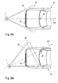
- the Fig. 2 and 4 illustrate the positioning of the handset 1 with respect to two different vehicles 16, 17, wherein the vehicle 16 of a first type in Fig. 2 in comparison to the vehicle 17 of a second type in Fig. 4 a significantly forward extending engine area and a lower-mounted license plate 18 has.
- the handset 1 For the data exchange with the toll collection device 20 of the vehicle 16 or the toll collection device 21 of the vehicle 17, the handset 1, the transmitter 11, 13 with a transmission cone 22 with an opening angle ⁇ .
- the handset 1 has the image acquisition unit 6 with a receiving lobe 23 (or receiving cone 23) with an opening angle ⁇ .
- the image acquisition unit 6 with a receiving lobe 23 (or receiving cone 23) with an opening angle ⁇ .
- the opening angle ⁇ of the receiving cone 23 of the image acquisition unit 6 is greater than the opening angle ⁇ of the transmitting cone 22.
- the optical axis A, ie the geometric center axis, of the transmitting cone 22 is inclined downwards relative to the optical axis B of the receiving cone 23.
- the display unit 5 preferably has three Display window 24A, 24B, 24C on (eg Fig. 3A ).
- the display windows 24A, 24B, 24C thus contain image sections of the image captured by the image acquisition unit 6, so that each of the display windows 24A, 24B, 24C is assigned a part of the recording cone 23.
- the uppermost display window 24A has a receiving area 23A and the lower display window 24B has a receiving area 23B (FIG. Fig. 2 ) and the center display window 24C, a receiving area 23C ( Fig.
- the toll collection device 20, 21 is visible in the uppermost display window 24A, the toll collection device 20, 21 is because of the overlap of the transmitting cone 22 with the receiving area 23A in the cone 22, so that the data from the toll collection device 20, 21 can be read.
- the license plate 18, 19 in the lower display window 24B or the middle display window 24C is visible, also the license plate 18, 19 can be detected and assigned to the read data.
- the suitable positioning of the handset 1 in particular also includes a suitable Inclination of the handset 1, so that the optical axis A with respect to a horizontal direction x an inclination angle ⁇ (see. Fig. 2 ) occupies.
- the two lower display windows 24B, 24C allow, in particular, the registration of the number plates 18, 19, which are arranged at different distances from the roadway, without the operator having to walk further away from the vehicle or closer to it.
- the display of the vehicle 16 of the first type on the display unit 5 shows the handset 1 from different distances D1, D2 of the handset 1 to the vehicle 16.
- the display unit 5 comprises the three display windows 24A, 24B, 24C which are compared to the illustration in FIG the FIGS. 3A and 3B can also be made smaller.
- the display windows 24B, 24C may be formed slightly larger than a license plate of the vehicle 16.
- the handset 1 is favorably positioned with respect to the vehicle 16 of the first type when the toll collection device 20 mounted in, for example, the dashed line is recognizable in the display window 24A and the license plate 18 in the display window 24B because the license plate 18 is relatively wide mounted on the bottom of the vehicle 16.
- the dashed line is recognizable in the display window 24A and the license plate 18 in the display window 24B because the license plate 18 is relatively wide mounted on the bottom of the vehicle 16.
- the distance D1 to the vehicle 16 is too large, for example, four meters, so that the maximum reading distance is exceeded to the toll collection device 20 and the reading of the toll collection device 20 will fail.
- the operator has the distance D2 to the vehicle 16 so far reduced, for example, to two meters that now the license plate 18 appears in the display window 24B, so read out in one step, both the toll collection device 20 and the license plate 18 can be detected.
- Figs. 5A and 5B an example is shown with a vehicle 17 of a second type whose license plate 19 is mounted higher than the license plate 18 of the vehicle 16. This results in other requirements for the distance to the vehicle 17.
- the handset 1 is favorably positioned with respect to the vehicle 17 of the second type when the toll collection device 21, which is mounted, for example, in the dashed line area, in the display window 24A and the license plate 19th can be seen in the display window 24B or in the display window 24C.
- the distance D1 is set at 1.2 meters so that the license plate 19 can be detected when the operator activates the display window 24B with the selection module 15 of the input unit 4.
- the license plate 19 may be detected at a greater distance D2 of, for example, two meters when the operator activates the display window 24C, see Fig. 5B ,
- FIGS. 6A and 6B can be seen on the example of vehicle 16 that the control of toll collection devices 20 with the handset 1 is feasible even if the toll collection device 20 and the license plate 18 are not mounted horizontally in the center of the vehicle 16.
- the license plate 18 mounted laterally on the vehicle 16
- the toll collection device 20 is mounted on the opposite side of the vehicle 16. In both cases, the control can be performed quickly and easily by suitable positioning of the handset 1.
- the handset In order to carry out the checking procedure, it is thus particularly favorable to position the handset such that the toll collection device 20, 21 in the display window 24A and the license plate 18, 19 can be seen in the display window 24B and / or 24C, depending on the type of vehicle 16, 17.
- the operator can then start the communication with the toll collection device 20, 21 by means of an input on the input unit 4.
- test signals are sent from the handset 1, which are answered accordingly by the toll collection device 20, 21, if the Handset 1 is suitably aligned with the vehicle 16, 17.
- This answer can be signaled to the operator by means of an output unit 10.
- the handset 1 then starts the readout process of the data from the toll collection device 20, 21 and the detection of the image data, in particular the license plate 18, 19.
- the successful implementation of this can also be signaled to the operator by means of the output unit 10.
- the data obtained can be stored in the memory 7, transmitted to the transmitter 8 and / or detected by a text recognition module 9.
- the operator first activates the uppermost display window 24A, aligns the handset 1 such that the toll collection device 20, 21 is visible in this display window 24A, and starts communication with the toll collection device 20, 21. Thereafter, the operator activates the lower or middle Display window 24B, 24C and aligns the handset 1 such that the license plate 18, 19 is visible in this display window 24B, 24C and starts the detection of the image data.
- the input unit 4 is also designed to be able to enter the license plate 18, 19 manually, if necessary, without using the image acquisition unit 6.
- the handset 1 can not be positioned so that the toll collection device 20, 21 in the display window 24A nor that the license plate 18, 19 in the display window 24B or 24C is visible.
- the operator estimates the positioning of the handset 1 and starts the communication with the toll-detecting device 20, 21. If necessary, for a successful communication, the position of the hand-held device 1 must be changed several times. To assist the operator with this assessment, a Field strength indicator are used.
- the license plate 18, 19 can also be detected by means of multiple experiments with the image acquisition unit 6 or manually entered.
Landscapes
- Engineering & Computer Science (AREA)
- Physics & Mathematics (AREA)
- General Physics & Mathematics (AREA)
- Theoretical Computer Science (AREA)
- Business, Economics & Management (AREA)
- Finance (AREA)
- Computer Hardware Design (AREA)
- Computer Networks & Wireless Communication (AREA)
- Human Computer Interaction (AREA)
- General Engineering & Computer Science (AREA)
- Multimedia (AREA)
- Devices For Checking Fares Or Tickets At Control Points (AREA)
Applications Claiming Priority (1)
| Application Number | Priority Date | Filing Date | Title |
|---|---|---|---|
| ATA50386/2014A AT515847B1 (de) | 2014-06-03 | 2014-06-03 | Handgerät und verfahren zur kontrolle eines mauterfassungsgeräts |
Publications (2)
| Publication Number | Publication Date |
|---|---|
| EP2953009A1 true EP2953009A1 (fr) | 2015-12-09 |
| EP2953009B1 EP2953009B1 (fr) | 2020-08-19 |
Family
ID=53476654
Family Applications (1)
| Application Number | Title | Priority Date | Filing Date |
|---|---|---|---|
| EP15170260.2A Active EP2953009B1 (fr) | 2014-06-03 | 2015-06-02 | Appareil portatif et procede de controle d'un appareil de peage routier |
Country Status (2)
| Country | Link |
|---|---|
| EP (1) | EP2953009B1 (fr) |
| AT (1) | AT515847B1 (fr) |
Citations (8)
| Publication number | Priority date | Publication date | Assignee | Title |
|---|---|---|---|---|
| EP1088286A2 (fr) * | 1998-06-18 | 2001-04-04 | MANNESMANN Aktiengesellschaft | Dispositif de controle cote route pour un appareil de peage installe dans un vehicule |
| WO2002058012A1 (fr) | 2001-01-17 | 2002-07-25 | Efkon Ag | Dispositif de communication sans fil, notamment mobile, destine a la communication avec des terminaux de communication dans des vehicules |
| DE102004002892A1 (de) * | 2004-01-20 | 2005-08-25 | Mohammad Djafar Nikandish | Verfahren, Vorrichtung und System zur Abwicklung eines Datentransfers im Zusammenhang mit der Lokalisierung von Kraftfahrzeugen |
| EP1739943A1 (fr) | 2005-06-29 | 2007-01-03 | Schweers Informationstechnologie GmbH | Appareil portatif mobile pour le traitement de données |
| EP1879151A2 (fr) | 2006-07-14 | 2008-01-16 | Vodafone Holding GmbH | Méthode de détection de l'emplacement d'un véhicule, unité embarquée et unité d'application |
| EP2450865A1 (fr) | 2010-11-04 | 2012-05-09 | Kapsch TrafficCom AG | Dispositifs et procédés de contrôle mobile pour véhicules |
| EP2530654A1 (fr) * | 2011-05-30 | 2012-12-05 | Toll Collect GmbH | Procédé d'installation d'un appareil de véhicule mobile et dispositif de véhicule doté d'un tel appareil de véhicule mobile |
| EP2624231A1 (fr) | 2012-02-02 | 2013-08-07 | Kapsch TrafficCom AG | Dispositifs et procédé de contrôle d'un système de péage routier |
-
2014
- 2014-06-03 AT ATA50386/2014A patent/AT515847B1/de active
-
2015
- 2015-06-02 EP EP15170260.2A patent/EP2953009B1/fr active Active
Patent Citations (8)
| Publication number | Priority date | Publication date | Assignee | Title |
|---|---|---|---|---|
| EP1088286A2 (fr) * | 1998-06-18 | 2001-04-04 | MANNESMANN Aktiengesellschaft | Dispositif de controle cote route pour un appareil de peage installe dans un vehicule |
| WO2002058012A1 (fr) | 2001-01-17 | 2002-07-25 | Efkon Ag | Dispositif de communication sans fil, notamment mobile, destine a la communication avec des terminaux de communication dans des vehicules |
| DE102004002892A1 (de) * | 2004-01-20 | 2005-08-25 | Mohammad Djafar Nikandish | Verfahren, Vorrichtung und System zur Abwicklung eines Datentransfers im Zusammenhang mit der Lokalisierung von Kraftfahrzeugen |
| EP1739943A1 (fr) | 2005-06-29 | 2007-01-03 | Schweers Informationstechnologie GmbH | Appareil portatif mobile pour le traitement de données |
| EP1879151A2 (fr) | 2006-07-14 | 2008-01-16 | Vodafone Holding GmbH | Méthode de détection de l'emplacement d'un véhicule, unité embarquée et unité d'application |
| EP2450865A1 (fr) | 2010-11-04 | 2012-05-09 | Kapsch TrafficCom AG | Dispositifs et procédés de contrôle mobile pour véhicules |
| EP2530654A1 (fr) * | 2011-05-30 | 2012-12-05 | Toll Collect GmbH | Procédé d'installation d'un appareil de véhicule mobile et dispositif de véhicule doté d'un tel appareil de véhicule mobile |
| EP2624231A1 (fr) | 2012-02-02 | 2013-08-07 | Kapsch TrafficCom AG | Dispositifs et procédé de contrôle d'un système de péage routier |
Also Published As
| Publication number | Publication date |
|---|---|
| EP2953009B1 (fr) | 2020-08-19 |
| AT515847A1 (de) | 2015-12-15 |
| AT515847B1 (de) | 2019-06-15 |
Similar Documents
| Publication | Publication Date | Title |
|---|---|---|
| DE69518967T2 (de) | Vorrichtung zur Ortung eines sich bewegenden Körpers mit Antwortgeber | |
| DE102015221439B3 (de) | Verfahren und Vorrichtung zur Auswahl und Übertragung von Sensordaten von einem ersten zu einem zweiten Kraftfahrzeug | |
| DE102009051463B4 (de) | Kraftfahrzeug, externe Steuerungsvorrichtung sowie Verfahren zum Durchführen eines Ausparkvorgangs eines Kraftfahrzeugs | |
| EP2312536B1 (fr) | Appareil de véhicule pour système de péage de routes | |
| EP3440654B1 (fr) | Procédé et système de détection de véhicules stationnés | |
| DE60201343T2 (de) | Verfahren und gerät zur überwachung | |
| EP2391995A1 (fr) | Procédé et dispositif permettant de détecter de manière probante un dépassement d'une vitesse maximale autorisée sur un tronçon d'une voie de circulation | |
| DE102013209298A1 (de) | System und Verfahren zum Erkennen von einem potentiell frei werdenden Parkplatz | |
| EP2383703B1 (fr) | Capteur radio pour un système de péages de routes sans fil | |
| WO2010066332A1 (fr) | Dispositif de surveillance des alentours d'un véhicule | |
| DE102017212221A1 (de) | Fernsteuerungsverfahren für ein Fahrerassistenzsystem, Fahrerassistenzsystem und damit versehenes Kraftfahrzeug | |
| DE102011102744A1 (de) | Verfahren zum Betreiben eines Kamerasystems eines Kraftfahrzeugs, Kraftfahrzeug sowie System mit einem Kraftfahrzeug und einer separaten Recheneinrichtung | |
| DE102007051961B4 (de) | Einrichtung zum Überwachen von sich in einem ausgezeichneten Bereich, insbesondere einem Werksgelände oder einem Parkhaus befindlichen Fahrzeugen | |
| EP3954595A1 (fr) | Procédé de fonctionnement d'un dispositif d'aide à la conduite d'un véhicule automobile à l'aide d'un dispositif de prédétermination d'objectif de navigation, dispositif de commande, dispositif de prédétermination de cible de navigation et véhicule automobile | |
| EP3866461A1 (fr) | Système de moniteur et de camera, procédé de fonctionnement d'un système de moniteur et de camera, véhicule automobile | |
| EP1352367A1 (fr) | Dispositif de communication sans fil, notamment mobile, destine a la communication avec des terminaux de communication dans des vehicules | |
| DE102012213132B4 (de) | Verfahren und Vorrichtung zur Fusion von Kameraaufnahmen von zumindest zwei Fahrzeugen | |
| DE102019003169A1 (de) | Fahrzeug-Kommunikations-Einrichtung eines ersten Fahrzeugs zur Kommunikation mit einem weitern sich in Sichtweite befindlichem Fahrzeug mit einer Fahrzeug-Kommunikations-Einrichtung | |
| AT515847B1 (de) | Handgerät und verfahren zur kontrolle eines mauterfassungsgeräts | |
| DE102009045496B4 (de) | Verfahren und Steuergerät zur Nutzung von Bildinformationen einer fahrzeugexternen Bildbereitstellungseinrichtung | |
| EP3221190B1 (fr) | Véhicule automobile | |
| DE102022106239B3 (de) | Verfahren zum Betreiben von Schließeinrichtungen mindestens zweier Kraftfahrzeuge, Steuereinrichtung, kraftfahrzeugexterne Servervorrichtung, tragbare Schlüsselvorrichtung, Kraftfahrzeug, und System zum Betreiben der Schließeinrichtungen zweier Kraftfahrzeuge | |
| DE602004001560T2 (de) | Verfahren und Vorrichtung zur Identifikation eines sich bewegenden Fahrzeugs | |
| DE10027136C2 (de) | Mobiles System zur Erzeugung eines virtuellen Displays | |
| AT523592B1 (de) | Informationsübertragung |
Legal Events
| Date | Code | Title | Description |
|---|---|---|---|
| PUAI | Public reference made under article 153(3) epc to a published international application that has entered the european phase |
Free format text: ORIGINAL CODE: 0009012 |
|
| AK | Designated contracting states |
Kind code of ref document: A1 Designated state(s): AL AT BE BG CH CY CZ DE DK EE ES FI FR GB GR HR HU IE IS IT LI LT LU LV MC MK MT NL NO PL PT RO RS SE SI SK SM TR |
|
| AX | Request for extension of the european patent |
Extension state: BA ME |
|
| 17P | Request for examination filed |
Effective date: 20160601 |
|
| RBV | Designated contracting states (corrected) |
Designated state(s): AL AT BE BG CH CY CZ DE DK EE ES FI FR GB GR HR HU IE IS IT LI LT LU LV MC MK MT NL NO PL PT RO RS SE SI SK SM TR |
|
| 19A | Proceedings stayed before grant |
Effective date: 20170531 |
|
| 19F | Resumption of proceedings before grant (after stay of proceedings) |
Effective date: 20191001 |
|
| RAP1 | Party data changed (applicant data changed or rights of an application transferred) |
Owner name: EFKON GMBH |
|
| STAA | Information on the status of an ep patent application or granted ep patent |
Free format text: STATUS: EXAMINATION IS IN PROGRESS |
|
| 17Q | First examination report despatched |
Effective date: 20191204 |
|
| GRAP | Despatch of communication of intention to grant a patent |
Free format text: ORIGINAL CODE: EPIDOSNIGR1 |
|
| STAA | Information on the status of an ep patent application or granted ep patent |
Free format text: STATUS: GRANT OF PATENT IS INTENDED |
|
| INTG | Intention to grant announced |
Effective date: 20200313 |
|
| GRAS | Grant fee paid |
Free format text: ORIGINAL CODE: EPIDOSNIGR3 |
|
| GRAA | (expected) grant |
Free format text: ORIGINAL CODE: 0009210 |
|
| STAA | Information on the status of an ep patent application or granted ep patent |
Free format text: STATUS: THE PATENT HAS BEEN GRANTED |
|
| AK | Designated contracting states |
Kind code of ref document: B1 Designated state(s): AL AT BE BG CH CY CZ DE DK EE ES FI FR GB GR HR HU IE IS IT LI LT LU LV MC MK MT NL NO PL PT RO RS SE SI SK SM TR |
|
| REG | Reference to a national code |
Ref country code: CH Ref legal event code: EP |
|
| REG | Reference to a national code |
Ref country code: DE Ref legal event code: R096 Ref document number: 502015013257 Country of ref document: DE |
|
| REG | Reference to a national code |
Ref country code: AT Ref legal event code: REF Ref document number: 1304703 Country of ref document: AT Kind code of ref document: T Effective date: 20200915 |
|
| REG | Reference to a national code |
Ref country code: IE Ref legal event code: FG4D Free format text: LANGUAGE OF EP DOCUMENT: GERMAN |
|
| REG | Reference to a national code |
Ref country code: LT Ref legal event code: MG4D |
|
| REG | Reference to a national code |
Ref country code: NL Ref legal event code: MP Effective date: 20200819 |
|
| PG25 | Lapsed in a contracting state [announced via postgrant information from national office to epo] |
Ref country code: BG Free format text: LAPSE BECAUSE OF FAILURE TO SUBMIT A TRANSLATION OF THE DESCRIPTION OR TO PAY THE FEE WITHIN THE PRESCRIBED TIME-LIMIT Effective date: 20201119 Ref country code: PT Free format text: LAPSE BECAUSE OF FAILURE TO SUBMIT A TRANSLATION OF THE DESCRIPTION OR TO PAY THE FEE WITHIN THE PRESCRIBED TIME-LIMIT Effective date: 20201221 Ref country code: GR Free format text: LAPSE BECAUSE OF FAILURE TO SUBMIT A TRANSLATION OF THE DESCRIPTION OR TO PAY THE FEE WITHIN THE PRESCRIBED TIME-LIMIT Effective date: 20201120 Ref country code: FI Free format text: LAPSE BECAUSE OF FAILURE TO SUBMIT A TRANSLATION OF THE DESCRIPTION OR TO PAY THE FEE WITHIN THE PRESCRIBED TIME-LIMIT Effective date: 20200819 Ref country code: SE Free format text: LAPSE BECAUSE OF FAILURE TO SUBMIT A TRANSLATION OF THE DESCRIPTION OR TO PAY THE FEE WITHIN THE PRESCRIBED TIME-LIMIT Effective date: 20200819 Ref country code: HR Free format text: LAPSE BECAUSE OF FAILURE TO SUBMIT A TRANSLATION OF THE DESCRIPTION OR TO PAY THE FEE WITHIN THE PRESCRIBED TIME-LIMIT Effective date: 20200819 Ref country code: NO Free format text: LAPSE BECAUSE OF FAILURE TO SUBMIT A TRANSLATION OF THE DESCRIPTION OR TO PAY THE FEE WITHIN THE PRESCRIBED TIME-LIMIT Effective date: 20201119 Ref country code: LT Free format text: LAPSE BECAUSE OF FAILURE TO SUBMIT A TRANSLATION OF THE DESCRIPTION OR TO PAY THE FEE WITHIN THE PRESCRIBED TIME-LIMIT Effective date: 20200819 |
|
| PG25 | Lapsed in a contracting state [announced via postgrant information from national office to epo] |
Ref country code: LV Free format text: LAPSE BECAUSE OF FAILURE TO SUBMIT A TRANSLATION OF THE DESCRIPTION OR TO PAY THE FEE WITHIN THE PRESCRIBED TIME-LIMIT Effective date: 20200819 Ref country code: PL Free format text: LAPSE BECAUSE OF FAILURE TO SUBMIT A TRANSLATION OF THE DESCRIPTION OR TO PAY THE FEE WITHIN THE PRESCRIBED TIME-LIMIT Effective date: 20200819 Ref country code: RS Free format text: LAPSE BECAUSE OF FAILURE TO SUBMIT A TRANSLATION OF THE DESCRIPTION OR TO PAY THE FEE WITHIN THE PRESCRIBED TIME-LIMIT Effective date: 20200819 Ref country code: NL Free format text: LAPSE BECAUSE OF FAILURE TO SUBMIT A TRANSLATION OF THE DESCRIPTION OR TO PAY THE FEE WITHIN THE PRESCRIBED TIME-LIMIT Effective date: 20200819 Ref country code: IS Free format text: LAPSE BECAUSE OF FAILURE TO SUBMIT A TRANSLATION OF THE DESCRIPTION OR TO PAY THE FEE WITHIN THE PRESCRIBED TIME-LIMIT Effective date: 20201219 |
|
| PG25 | Lapsed in a contracting state [announced via postgrant information from national office to epo] |
Ref country code: DK Free format text: LAPSE BECAUSE OF FAILURE TO SUBMIT A TRANSLATION OF THE DESCRIPTION OR TO PAY THE FEE WITHIN THE PRESCRIBED TIME-LIMIT Effective date: 20200819 Ref country code: CZ Free format text: LAPSE BECAUSE OF FAILURE TO SUBMIT A TRANSLATION OF THE DESCRIPTION OR TO PAY THE FEE WITHIN THE PRESCRIBED TIME-LIMIT Effective date: 20200819 Ref country code: EE Free format text: LAPSE BECAUSE OF FAILURE TO SUBMIT A TRANSLATION OF THE DESCRIPTION OR TO PAY THE FEE WITHIN THE PRESCRIBED TIME-LIMIT Effective date: 20200819 Ref country code: SM Free format text: LAPSE BECAUSE OF FAILURE TO SUBMIT A TRANSLATION OF THE DESCRIPTION OR TO PAY THE FEE WITHIN THE PRESCRIBED TIME-LIMIT Effective date: 20200819 Ref country code: RO Free format text: LAPSE BECAUSE OF FAILURE TO SUBMIT A TRANSLATION OF THE DESCRIPTION OR TO PAY THE FEE WITHIN THE PRESCRIBED TIME-LIMIT Effective date: 20200819 |
|
| REG | Reference to a national code |
Ref country code: DE Ref legal event code: R097 Ref document number: 502015013257 Country of ref document: DE |
|
| PG25 | Lapsed in a contracting state [announced via postgrant information from national office to epo] |
Ref country code: AL Free format text: LAPSE BECAUSE OF FAILURE TO SUBMIT A TRANSLATION OF THE DESCRIPTION OR TO PAY THE FEE WITHIN THE PRESCRIBED TIME-LIMIT Effective date: 20200819 Ref country code: ES Free format text: LAPSE BECAUSE OF FAILURE TO SUBMIT A TRANSLATION OF THE DESCRIPTION OR TO PAY THE FEE WITHIN THE PRESCRIBED TIME-LIMIT Effective date: 20200819 |
|
| PLBE | No opposition filed within time limit |
Free format text: ORIGINAL CODE: 0009261 |
|
| STAA | Information on the status of an ep patent application or granted ep patent |
Free format text: STATUS: NO OPPOSITION FILED WITHIN TIME LIMIT |
|
| PG25 | Lapsed in a contracting state [announced via postgrant information from national office to epo] |
Ref country code: SK Free format text: LAPSE BECAUSE OF FAILURE TO SUBMIT A TRANSLATION OF THE DESCRIPTION OR TO PAY THE FEE WITHIN THE PRESCRIBED TIME-LIMIT Effective date: 20200819 |
|
| 26N | No opposition filed |
Effective date: 20210520 |
|
| PG25 | Lapsed in a contracting state [announced via postgrant information from national office to epo] |
Ref country code: IT Free format text: LAPSE BECAUSE OF FAILURE TO SUBMIT A TRANSLATION OF THE DESCRIPTION OR TO PAY THE FEE WITHIN THE PRESCRIBED TIME-LIMIT Effective date: 20200819 |
|
| PG25 | Lapsed in a contracting state [announced via postgrant information from national office to epo] |
Ref country code: SI Free format text: LAPSE BECAUSE OF FAILURE TO SUBMIT A TRANSLATION OF THE DESCRIPTION OR TO PAY THE FEE WITHIN THE PRESCRIBED TIME-LIMIT Effective date: 20200819 |
|
| PG25 | Lapsed in a contracting state [announced via postgrant information from national office to epo] |
Ref country code: MC Free format text: LAPSE BECAUSE OF FAILURE TO SUBMIT A TRANSLATION OF THE DESCRIPTION OR TO PAY THE FEE WITHIN THE PRESCRIBED TIME-LIMIT Effective date: 20200819 |
|
| REG | Reference to a national code |
Ref country code: CH Ref legal event code: PL |
|
| GBPC | Gb: european patent ceased through non-payment of renewal fee |
Effective date: 20210602 |
|
| PG25 | Lapsed in a contracting state [announced via postgrant information from national office to epo] |
Ref country code: LU Free format text: LAPSE BECAUSE OF NON-PAYMENT OF DUE FEES Effective date: 20210602 |
|
| PG25 | Lapsed in a contracting state [announced via postgrant information from national office to epo] |
Ref country code: LI Free format text: LAPSE BECAUSE OF NON-PAYMENT OF DUE FEES Effective date: 20210630 Ref country code: IE Free format text: LAPSE BECAUSE OF NON-PAYMENT OF DUE FEES Effective date: 20210602 Ref country code: GB Free format text: LAPSE BECAUSE OF NON-PAYMENT OF DUE FEES Effective date: 20210602 Ref country code: CH Free format text: LAPSE BECAUSE OF NON-PAYMENT OF DUE FEES Effective date: 20210630 |
|
| PG25 | Lapsed in a contracting state [announced via postgrant information from national office to epo] |
Ref country code: FR Free format text: LAPSE BECAUSE OF NON-PAYMENT OF DUE FEES Effective date: 20210630 |
|
| REG | Reference to a national code |
Ref country code: AT Ref legal event code: MM01 Ref document number: 1304703 Country of ref document: AT Kind code of ref document: T Effective date: 20210602 |
|
| PGFP | Annual fee paid to national office [announced via postgrant information from national office to epo] |
Ref country code: BE Payment date: 20220621 Year of fee payment: 8 |
|
| PG25 | Lapsed in a contracting state [announced via postgrant information from national office to epo] |
Ref country code: AT Free format text: LAPSE BECAUSE OF NON-PAYMENT OF DUE FEES Effective date: 20210602 |
|
| PG25 | Lapsed in a contracting state [announced via postgrant information from national office to epo] |
Ref country code: HU Free format text: LAPSE BECAUSE OF FAILURE TO SUBMIT A TRANSLATION OF THE DESCRIPTION OR TO PAY THE FEE WITHIN THE PRESCRIBED TIME-LIMIT; INVALID AB INITIO Effective date: 20150602 |
|
| PG25 | Lapsed in a contracting state [announced via postgrant information from national office to epo] |
Ref country code: CY Free format text: LAPSE BECAUSE OF FAILURE TO SUBMIT A TRANSLATION OF THE DESCRIPTION OR TO PAY THE FEE WITHIN THE PRESCRIBED TIME-LIMIT Effective date: 20200819 |
|
| REG | Reference to a national code |
Ref country code: BE Ref legal event code: MM Effective date: 20230630 |
|
| PG25 | Lapsed in a contracting state [announced via postgrant information from national office to epo] |
Ref country code: MK Free format text: LAPSE BECAUSE OF FAILURE TO SUBMIT A TRANSLATION OF THE DESCRIPTION OR TO PAY THE FEE WITHIN THE PRESCRIBED TIME-LIMIT Effective date: 20200819 |
|
| PG25 | Lapsed in a contracting state [announced via postgrant information from national office to epo] |
Ref country code: BE Free format text: LAPSE BECAUSE OF NON-PAYMENT OF DUE FEES Effective date: 20230630 |
|
| PG25 | Lapsed in a contracting state [announced via postgrant information from national office to epo] |
Ref country code: TR Free format text: LAPSE BECAUSE OF FAILURE TO SUBMIT A TRANSLATION OF THE DESCRIPTION OR TO PAY THE FEE WITHIN THE PRESCRIBED TIME-LIMIT Effective date: 20200819 |
|
| PG25 | Lapsed in a contracting state [announced via postgrant information from national office to epo] |
Ref country code: MT Free format text: LAPSE BECAUSE OF FAILURE TO SUBMIT A TRANSLATION OF THE DESCRIPTION OR TO PAY THE FEE WITHIN THE PRESCRIBED TIME-LIMIT Effective date: 20200819 |
|
| PGFP | Annual fee paid to national office [announced via postgrant information from national office to epo] |
Ref country code: DE Payment date: 20250618 Year of fee payment: 11 |