EP2953202A2 - Batterieladegerät mit automatischer Spannungserkennung - Google Patents
Batterieladegerät mit automatischer Spannungserkennung Download PDFInfo
- Publication number
- EP2953202A2 EP2953202A2 EP15000370.5A EP15000370A EP2953202A2 EP 2953202 A2 EP2953202 A2 EP 2953202A2 EP 15000370 A EP15000370 A EP 15000370A EP 2953202 A2 EP2953202 A2 EP 2953202A2
- Authority
- EP
- European Patent Office
- Prior art keywords
- battery
- voltage
- battery charger
- nominal
- charger
- Prior art date
- Legal status (The legal status is an assumption and is not a legal conclusion. Google has not performed a legal analysis and makes no representation as to the accuracy of the status listed.)
- Granted
Links
Images


Classifications
-
- G—PHYSICS
- G01—MEASURING; TESTING
- G01R—MEASURING ELECTRIC VARIABLES; MEASURING MAGNETIC VARIABLES
- G01R31/00—Arrangements for testing electric properties; Arrangements for locating electric faults; Arrangements for electrical testing characterised by what is being tested not provided for elsewhere
- G01R31/36—Arrangements for testing, measuring or monitoring the electrical condition of accumulators or electric batteries, e.g. capacity or state of charge [SoC]
- G01R31/382—Arrangements for monitoring battery or accumulator variables, e.g. SoC
- G01R31/3835—Arrangements for monitoring battery or accumulator variables, e.g. SoC involving only voltage measurements
-
- H—ELECTRICITY
- H01—ELECTRIC ELEMENTS
- H01M—PROCESSES OR MEANS, e.g. BATTERIES, FOR THE DIRECT CONVERSION OF CHEMICAL ENERGY INTO ELECTRICAL ENERGY
- H01M10/00—Secondary cells; Manufacture thereof
- H01M10/42—Methods or arrangements for servicing or maintenance of secondary cells or secondary half-cells
- H01M10/44—Methods for charging or discharging
-
- H—ELECTRICITY
- H02—GENERATION; CONVERSION OR DISTRIBUTION OF ELECTRIC POWER
- H02J—ELECTRIC POWER NETWORKS; CIRCUIT ARRANGEMENTS OR SYSTEMS FOR SUPPLYING OR DISTRIBUTING ELECTRIC POWER; SYSTEMS FOR STORING ELECTRIC ENERGY
- H02J7/00—Circuit arrangements for charging or discharging batteries or for supplying loads from batteries
-
- H—ELECTRICITY
- H02—GENERATION; CONVERSION OR DISTRIBUTION OF ELECTRIC POWER
- H02J—ELECTRIC POWER NETWORKS; CIRCUIT ARRANGEMENTS OR SYSTEMS FOR SUPPLYING OR DISTRIBUTING ELECTRIC POWER; SYSTEMS FOR STORING ELECTRIC ENERGY
- H02J7/00—Circuit arrangements for charging or discharging batteries or for supplying loads from batteries
- H02J7/40—Circuit arrangements for charging or discharging batteries or for supplying loads from batteries characterised by the exchange of charge or discharge related data
- H02J7/443—Circuit arrangements for charging or discharging batteries or for supplying loads from batteries characterised by the exchange of charge or discharge related data using passive battery identification means, e.g. resistors or capacitors
- H02J7/445—Circuit arrangements for charging or discharging batteries or for supplying loads from batteries characterised by the exchange of charge or discharge related data using passive battery identification means, e.g. resistors or capacitors in response to measured battery parameters, e.g. voltage, current or temperature profile
-
- H—ELECTRICITY
- H02—GENERATION; CONVERSION OR DISTRIBUTION OF ELECTRIC POWER
- H02J—ELECTRIC POWER NETWORKS; CIRCUIT ARRANGEMENTS OR SYSTEMS FOR SUPPLYING OR DISTRIBUTING ELECTRIC POWER; SYSTEMS FOR STORING ELECTRIC ENERGY
- H02J7/00—Circuit arrangements for charging or discharging batteries or for supplying loads from batteries
- H02J7/485—Circuit arrangements for charging or discharging batteries or for supplying loads from batteries with provisions for charging different types of batteries
-
- H—ELECTRICITY
- H02—GENERATION; CONVERSION OR DISTRIBUTION OF ELECTRIC POWER
- H02J—ELECTRIC POWER NETWORKS; CIRCUIT ARRANGEMENTS OR SYSTEMS FOR SUPPLYING OR DISTRIBUTING ELECTRIC POWER; SYSTEMS FOR STORING ELECTRIC ENERGY
- H02J7/00—Circuit arrangements for charging or discharging batteries or for supplying loads from batteries
- H02J7/80—Circuit arrangements for charging or discharging batteries or for supplying loads from batteries including monitoring or indicating arrangements
- H02J7/82—Control of state of charge [SOC]
-
- H—ELECTRICITY
- H02—GENERATION; CONVERSION OR DISTRIBUTION OF ELECTRIC POWER
- H02J—ELECTRIC POWER NETWORKS; CIRCUIT ARRANGEMENTS OR SYSTEMS FOR SUPPLYING OR DISTRIBUTING ELECTRIC POWER; SYSTEMS FOR STORING ELECTRIC ENERGY
- H02J7/00—Circuit arrangements for charging or discharging batteries or for supplying loads from batteries
- H02J7/80—Circuit arrangements for charging or discharging batteries or for supplying loads from batteries including monitoring or indicating arrangements
-
- H—ELECTRICITY
- H02—GENERATION; CONVERSION OR DISTRIBUTION OF ELECTRIC POWER
- H02J—ELECTRIC POWER NETWORKS; CIRCUIT ARRANGEMENTS OR SYSTEMS FOR SUPPLYING OR DISTRIBUTING ELECTRIC POWER; SYSTEMS FOR STORING ELECTRIC ENERGY
- H02J7/00—Circuit arrangements for charging or discharging batteries or for supplying loads from batteries
- H02J7/80—Circuit arrangements for charging or discharging batteries or for supplying loads from batteries including monitoring or indicating arrangements
- H02J7/84—Control of state of health [SOH]
-
- Y—GENERAL TAGGING OF NEW TECHNOLOGICAL DEVELOPMENTS; GENERAL TAGGING OF CROSS-SECTIONAL TECHNOLOGIES SPANNING OVER SEVERAL SECTIONS OF THE IPC; TECHNICAL SUBJECTS COVERED BY FORMER USPC CROSS-REFERENCE ART COLLECTIONS [XRACs] AND DIGESTS
- Y02—TECHNOLOGIES OR APPLICATIONS FOR MITIGATION OR ADAPTATION AGAINST CLIMATE CHANGE
- Y02E—REDUCTION OF GREENHOUSE GAS [GHG] EMISSIONS, RELATED TO ENERGY GENERATION, TRANSMISSION OR DISTRIBUTION
- Y02E60/00—Enabling technologies; Technologies with a potential or indirect contribution to GHG emissions mitigation
- Y02E60/10—Energy storage using batteries
Definitions
- the present invention relates to a battery charger configured to be connected to an external battery by way of external battery cables and more particularly to a battery charger with automatic voltage detection which automatically determines the nominal voltage of the battery connected to its terminals and charges the battery as a function of the detected nominal voltage irrespective of the nominal voltage selected by a user.
- the battery charger Since each different type of battery needs to be charged according to a specific charging algorithm for the specific battery, it is necessary for the battery charger to be properly configured for the battery type and nominal voltage of the battery connected to its terminals.
- Some known battery chargers require the user to determine the battery type and nominal voltage of a battery connected to its terminals. Such battery chargers require the user to manually configure the battery charger.
- Other known battery chargers automatically determine the battery type and the nominal voltage of the battery connected to its terminals and automatically configure the battery charger.
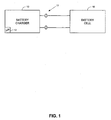
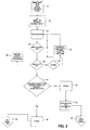
- the battery charger 10 initializes the system, as indicated by logic blocks 18 and 20. More specifically, the input/output (I/O) ports on the microprocessor 12 are initialized along with the system clock.
- the analog to digital converters which may be external or on board with the microprocessor 12, are calibrated and all system variables are initialized. In addition all LEDs are tested and set to their initial state.
- step 22 the system proceeds to step 22 and checks the voltage across its terminals 17.
- the battery terminals 17 are coupled to the ADC .
- the analog battery voltage is converted to a digital value and compared with a predetermined value.
- the system "reads" the voltage across the battery charger terminals and determines whether the voltage across the battery charger terminals is greater than a nominal amount, for example, 0.2 volts DC, a value simply indicative of whether a battery is connected across the battery terminals. If there is no battery connected across the battery charger terminals, the system loops back to steps 22 and 24 and waits for a battery to be connected to the battery charger terminals.
- the system initially makes a simple voltage measurement in order to determine whether the battery connected to its terminals has a nominal 6 volts or a nominal 12 volts. More specifically, the system initially determines in step 24 whether the voltage across the battery charger terminals is greater than the nominal amount, illustrated in Fig. 2 as 0.2 volts DC. If so, the system assumes a battery of unknown nominal voltage is connected across its terminals.
- the system determines the position of the mode switch in step 28.
- mode switches are used to initially select the charging algorithm to be delivered by the battery charger to the battery connected to its terminals 17.
- the mode switch (not shown) is user selectable between 6 volts and 12 volts.
- step 26 the system measures the battery voltage and compares the measured voltage with the voltage designated by the position of the mode selector switch to determine if the user selectable mode switch is set for the correct mode. If the mode switch is set at 12 volts, the system initially determines if the measured voltage is less than 17 volts DC or 8,5 volts DC if the mode switch is set in a 6 volt mode. If the measured voltage is greater than 17 volts DC, the system checks in step 28 whether the user selectable mode switch was set for the 6 Volt mode.
- the system If the measured voltage is greater than 8.5 volts DC the user selectable mode switch set for the 6 volts DC mode, the system assumes that a 12 volt DC battery is connected to the battery charger terminal 17 In this case, the system over-rides the user selected position for the mode switch and configures the system to charge battery in accordance with the 12 volt algorithm, as set forth below, as indicated in step 30 and proceeds to step 32. In addition, the system optionally toggles one or more LEDs indicating the over-ride of the user selected mode position in step 35. The system then loops back to the logic block 22 and repeats steps 24 and 26. This time, since the battery mode was automatically set for the 12 volt mode by the battery charger, the measured voltage will be less than 17 volts and the system will proceed to step 34.
- step 26 the system checks in step 26 whether the voltage connected to its terminals 17 is less than 17 volts DC and greater than 7.5 volts DC. the system assumes a 12 volt battery is connected to the battery charger and proceeds to steps 34 and 32 and charges the battery according to the 12 volt battery charger algorithm.
- steps 26, 28, 30 and 34 may be eliminated.
- the system may be configured to proceed from step 24 directly to steps 34 and 32.
- the system must determine whether the battery connected to its terminals is a depleted 12 volt battery or a 6 volt DC battery. Accordingly, if the measured voltage is less than 7.5 volts DC, the system initially assumes that a 6 volt DC battery is attached to its terminals, as indicated in step 36. In order to differentiate between a depleted 12 volt battery and a 6 volt battery when the measured voltage across the battery charger terminals is less than 7.5 volts, a battery test is conducted, as indicated by the logic block 38.
- the test for determining whether the ⁇ 7.5 volts measured in step 26 represents a 6 volt battery or a depleted 12 volt battery is illustrated in Fig. 7 .
- the test consists forcing a test current, for example, 2-3 amperes DC, through the battery connected to its terminals for a short time, for example, 1 second, as indicated in step 40.
- the peak ripple voltage, i.e. closed circuit voltage, for example, across the battery 16 is measured in step 42. If the peak ripple voltage is greater than, for example, 11 volts DC, the system assumes the battery connected across the battery charger terminals is a depleted 12 volt battery. In this situation, the system proceeds to steps 44 and 46 and initiates charging of the battery in a 12 volt mode of operation. Alternatively, if the ripple voltage is less than 11 volts DC, the system proceeds to step 48 and initiates charging of the battery in a 6 volt mode of operation.
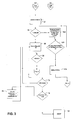
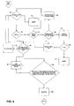
- Figs 3 and 4 illustrate the 6 volt and 12 volt charging modes.
- Fig. 5 illustrates a maintenance charging mode.
- Fig. 6 illustrates a desulfation mode.
- the system determines whether the battery connected to its terminals suffers from a condition commonly known as sulfation.
- the charging current is limited, for example, to a nominal amount, for example, 1.5 amps DC, as indicated in step 56.
- the system repeatedly measures the voltage of the battery connected across its terminals 17. When the voltage exceeds 9 volts in a 12 volt charging mode, for example, as indicated by the logic block 58, the system assumes that the battery connected to its terminals is a 12 volt battery and proceeds with a normal 12 volt charge with safeguards as discussed herein.
- a 6 volt charging mode if the battery voltage exceeds 4.5 volts, the system proceeds with a normal 6 volt charge.
- the battery In both the 6 volt mode and the 12 volt mode, the battery is charged until the time out period runs, for example, 2 hours, or the battery voltage exceeds 12 volts DC in a 12 volt mode or exceeds 6 volts in a 6 volt mode, as indicated by the logic block 60 ( Fig. 3 ).
- the time out period functions as a safety check to make sure that the battery voltage increases to at least 4.5/9.0 volts in a 6/12 volt mode in for example, 2 hours.
- the system continually checks whether the voltage of the battery connected to its terminals 17 is ⁇ Vmax, Vmax represents the previously measured highest voltage of the battery.
- the system repeatedly checks the voltage of the battery in step 62 and whether the 2 hour timer has timed out in step 64.
- step 70 If the battery charger was initially configured for a 6 volt operating mode, and the battery voltage exceeds, for example 9.5 volts DC, as indicated in step 70, the system proceeds to step 72 and charges the battery in a 12 volt charging mode. During conditions in which the battery voltage is ⁇ 9.5 volts and the system is configured in a 6 volt DC charging mode, as indicated by the logic block 70, the system assumes a 6 volt charging mode. During a 6 volt charging mode, the system regulates the battery voltage at Vmax, i.e. the previously measured highest DC voltage in step 84. The system also continues to regulate the rate of change of changing current, for example, at a constant current, i.e.
- the maintenance charge mode is illustrated in Fig. 5 .
- the charging LED is turned off and the maintenance charge LED for a predetermined time period, for example, 60 seconds.
- the system checks whether the battery voltage Vbat ⁇ the maintenance charge voltage Vmaint, for example, 12.8 volts DC in a 12 volt charging mode and 6.4 volts DC in a 6 volt charging mode. If the battery voltage Vbat ⁇ the maintenance charge voltage Vmaint , the system and continuously loops back to step 90 and maintains the maintenance charge LEDs on until the battery is disconnected.
- the system is configured in order to regulate the battery voltage at the maintenance voltage Vmaint, as indicated in step 96.
- a maintenance charging current is pumped into the battery in order to regulate the battery voltage at the maintenance voltage Vmaint.
- the system checks whether the battery voltage Vbat has climbed above the maintenance voltage Vmaint, by a nominal amount, for example, 0.1 volts DC. If so, the system maintains the maintenance charge LEDs on and continues regulating the battery voltage at the maintenance charge voltage Vmaint.
- the system will attempt to maintain the battery at 13.2 volts DC in a 12 volt mode and 6.6 volts DC in a 6 volt mode with up to a nominal maintenance charging current, for example, up to 500 mAmps, as indicated in step 100 .
- a nominal maintenance charging current for example, up to 500 mAmps, as indicated in step 100 .
- the system repeatedly checks the battery voltage. If the battery voltage in a 12 volt mode drops below, for example, 12.8 volts in a 12 volt mode or 6.4 volts in a 6 volt mode, as indicated in step 102, the system initiates a full 12 volt or 6 volt charge in step 104. If the battery voltage is > 12.8 volts in a 12 volt mode or > than 6.4 volts in a 6 volt mode, the system stays in a maintenance charge mode and repeats steps 94-102.
- a sulfation condition is a condition of lead acid batteries that will not hold a charge due to the crystallization of lead sulfate.
- Desulfation is a process of repeatedly sending short current surges through the damaged battery. The current pulses tend to break down and dissolve the sulfate crystals, restoring some of the battery's capacity over time.
- the system checks for a sulfation condition.
- the system checks the initial voltage of the battery and then ramps up the charging current from a minimum to, for example 1 amp, in step 104 and checks the peak battery voltage in step 106. If the peak voltage is > 11 volts, for example, but the initial voltage was less than 3 volts , for example, the system assumes a sulfation condition exists and initiates a desulfation charge as indicated by the logic block 108.
- the charger 10 will try to maintain the battery voltage at around 15.4V with a current with a relatively low maximum, If the battery is salvageable, the current will hit the maximum and the voltage will begin to drift down. If it drifts down below, for example, 11V, then the battery is most likely a 6V battery. Rerunning the battery detection test mentioned above can be used to confirm the determination. More specifically, the desulfation charge mode is illustrated in Fig. 6 . In a desulfation charge mode, desulfation LEDS are flashed in step 110. The desulfation charge is conducted for a set time period, 8 hours, for example, as indicated by the logic block 112.
- the desulfation charge is terminated, as indicated by the logic block 114.
- the battery voltage is regulated at, for example, 15.4 volts , as indicated by the logic block 116. by way of current pulses are applied to the battery. The current pulses are applied to the battery until the battery accepts charge.
- the battery charger is actually maintaining the peak ripple voltage at the high voltage.
- the actual battery voltage when the charger is off during this period is generally unreliable as an indicator of battery health from 0.1 V on up.
- the system determines if the battery has been recovered and can accept charge if the battery begins to take current, i.e. the charging duty cycle has increased to a sufficient level or if the peak ripple has come down substantially below, for example 11 volts.
- the system determines that the battery has recovered, y the battery is initially charged in a 6 volt mode , as indicated by the logic box 120.
- the nominal voltage of the battery is subsequently determined, as discussed above and the battery is charged as a function of its nominal voltage.
Landscapes
- Engineering & Computer Science (AREA)
- Power Engineering (AREA)
- Manufacturing & Machinery (AREA)
- Chemical & Material Sciences (AREA)
- Chemical Kinetics & Catalysis (AREA)
- Electrochemistry (AREA)
- General Chemical & Material Sciences (AREA)
- Physics & Mathematics (AREA)
- General Physics & Mathematics (AREA)
- Charge And Discharge Circuits For Batteries Or The Like (AREA)
- Secondary Cells (AREA)
Applications Claiming Priority (2)
| Application Number | Priority Date | Filing Date | Title |
|---|---|---|---|
| US12/504,223 US8575899B2 (en) | 2009-07-16 | 2009-07-16 | Battery charger with automatic voltage detection |
| EP10800331.0A EP2454778B1 (de) | 2009-07-16 | 2010-07-07 | Batterieladegerät mit automatischer spannungserkennung |
Related Parent Applications (2)
| Application Number | Title | Priority Date | Filing Date |
|---|---|---|---|
| EP10800331.0A Division-Into EP2454778B1 (de) | 2009-07-16 | 2010-07-07 | Batterieladegerät mit automatischer spannungserkennung |
| EP10800331.0A Division EP2454778B1 (de) | 2009-07-16 | 2010-07-07 | Batterieladegerät mit automatischer spannungserkennung |
Publications (3)
| Publication Number | Publication Date |
|---|---|
| EP2953202A2 true EP2953202A2 (de) | 2015-12-09 |
| EP2953202A3 EP2953202A3 (de) | 2016-03-30 |
| EP2953202B1 EP2953202B1 (de) | 2018-06-13 |
Family
ID=43449692
Family Applications (2)
| Application Number | Title | Priority Date | Filing Date |
|---|---|---|---|
| EP10800331.0A Active EP2454778B1 (de) | 2009-07-16 | 2010-07-07 | Batterieladegerät mit automatischer spannungserkennung |
| EP15000370.5A Active EP2953202B1 (de) | 2009-07-16 | 2010-07-07 | Batterieladegerät mit automatischer Spannungserkennung |
Family Applications Before (1)
| Application Number | Title | Priority Date | Filing Date |
|---|---|---|---|
| EP10800331.0A Active EP2454778B1 (de) | 2009-07-16 | 2010-07-07 | Batterieladegerät mit automatischer spannungserkennung |
Country Status (5)
| Country | Link |
|---|---|
| US (4) | US8575899B2 (de) |
| EP (2) | EP2454778B1 (de) |
| BR (1) | BRPI1014567A2 (de) |
| ES (1) | ES2732817T3 (de) |
| WO (1) | WO2011008600A1 (de) |
Cited By (2)
| Publication number | Priority date | Publication date | Assignee | Title |
|---|---|---|---|---|
| WO2017197383A1 (en) * | 2016-05-13 | 2017-11-16 | Schumacher Electric Corporation | Battery state detection system and method |
| EP3455641A4 (de) * | 2016-05-13 | 2019-12-11 | Schumacher Electric Corporation | Batteriezustandserfassungssystem und -verfahren |
Families Citing this family (21)
| Publication number | Priority date | Publication date | Assignee | Title |
|---|---|---|---|---|
| US8575899B2 (en) | 2009-07-16 | 2013-11-05 | Schumacher Electric Corporation | Battery charger with automatic voltage detection |
| DE102011111993A1 (de) * | 2011-08-31 | 2013-02-28 | Volkswagen Aktiengesellschaft | Verfahren und Vorrichtung zum Laden eines Energiespeichers eines Fahrzeugs |
| US9585405B2 (en) * | 2013-07-19 | 2017-03-07 | Tenderbuck, LLC | Portable device and method for improved meat tenderization |
| US9360530B2 (en) | 2013-08-19 | 2016-06-07 | Google Technology Holdings LLC | Method and system for energy storage capacity estimation of battery cells |
| CN203933073U (zh) | 2014-04-28 | 2014-11-05 | 王熙宁 | 一种新型汽车充电器 |
| US9007015B1 (en) | 2014-07-03 | 2015-04-14 | The Noco Company | Portable vehicle battery jump start apparatus with safety protection |
| US11458851B2 (en) | 2014-07-03 | 2022-10-04 | The Noco Company | Jump starting apparatus |
| ES2860923T3 (es) | 2014-08-14 | 2021-10-05 | Schumacher Electric Corp | Reforzador de batería multifuncional compacto |
| WO2016025861A1 (en) | 2014-08-14 | 2016-02-18 | Schumacher Electric Corp. | Battery charger status control system and method |
| US10063080B2 (en) * | 2015-12-08 | 2018-08-28 | Blackberry Limited | Electronic device including battery and method of controlling same for charging the battery |
| TWI591477B (zh) * | 2016-05-31 | 2017-07-11 | 廣達電腦股份有限公司 | 電子裝置 |
| US10823786B2 (en) * | 2017-07-28 | 2020-11-03 | Northstar Battery Company, Llc | Battery with internal monitoring system |
| US12074434B2 (en) | 2017-09-22 | 2024-08-27 | The Noco Company | Portable vehicle battery jump starter with air pump |
| JP7018507B2 (ja) | 2017-12-14 | 2022-02-10 | ザ・ノコ・カンパニー | エアポンプを備えた携帯型車両バッテリジャンプスタート装置 |
| US11674490B2 (en) * | 2018-08-30 | 2023-06-13 | Schumacher Electric Corporation | Multifunctional battery booster |
| WO2022071702A1 (ko) * | 2020-09-29 | 2022-04-07 | 삼성전자 주식회사 | 탈착 가능한 배터리를 포함하는 전자 장치 및 이의 동작 방법 |
| US11973366B2 (en) | 2020-10-20 | 2024-04-30 | Schumacher Electric Corporation | Battery booster |
| US11888340B2 (en) * | 2020-12-04 | 2024-01-30 | Schneider Electric It Corporation | Method to enhance the life of a lithium battery |
| US11527897B1 (en) | 2021-05-21 | 2022-12-13 | Deltran Operations Usa, Inc. | Battery charger and engine jump start system with automatic operating mode via a single output receptacle |
| DE102021127702B4 (de) * | 2021-10-25 | 2023-05-11 | Einhell Germany Ag | Ladevorrichtung für ein Akkupack zur Installation an oder in einer Gebäudewand |
| US20240088692A1 (en) * | 2022-09-09 | 2024-03-14 | Renesas Electronics America Inc. | Battery status detection using forced battery mode |
Citations (6)
| Publication number | Priority date | Publication date | Assignee | Title |
|---|---|---|---|---|
| US5729115A (en) | 1996-06-11 | 1998-03-17 | Ericsson Inc. | Apparatus and method for identifying and charging batteries of different types |
| US6384575B1 (en) | 2000-11-28 | 2002-05-07 | Delta Electronics, Inc. | Battery charger capable of charging different size of batteries |
| US6625477B1 (en) | 1996-06-12 | 2003-09-23 | Ericsson Inc. | Apparatus and method for identifying and charging batteries of different types |
| US20050088144A1 (en) | 2003-10-23 | 2005-04-28 | Schumacher Electric Corporation | System and method for charging batteries |
| US20070247105A1 (en) | 2006-02-24 | 2007-10-25 | Black & Decker Inc. | Portable battery charger |
| US7468596B2 (en) | 2004-11-18 | 2008-12-23 | Jeckson Electric Company Limited | Battery charger for various sizes of batteries with selection of appropriate charging power |
Family Cites Families (32)
| Publication number | Priority date | Publication date | Assignee | Title |
|---|---|---|---|---|
| US4956597A (en) * | 1987-02-04 | 1990-09-11 | American Monarch Corporation | Method and apparatus for charging batteries |
| US4847546A (en) * | 1987-04-07 | 1989-07-11 | Bobier Electronics, Inc. | Solar panel output enhancement circuit |
| US5233230A (en) * | 1990-05-04 | 1993-08-03 | Bonar George D | Power cord |
| US5808443A (en) * | 1996-12-19 | 1998-09-15 | Lundstrom; John W. | Battery charging method |
| AU5320599A (en) * | 1998-07-27 | 2000-02-21 | Midtronics, Inc. | Apparatus and method for carrying out diagnostic tests on batteries and for rapidly charging batteries |
| US6327663B2 (en) * | 1998-10-21 | 2001-12-04 | Advanced Micro Devices, Inc. | System and method for processor dual voltage detection and over stress protection |
| US6268665B1 (en) * | 1999-05-10 | 2001-07-31 | Mutipower, Inc. | Testing battery power source of uninterruptible power supply |
| US6377029B1 (en) * | 2000-04-26 | 2002-04-23 | Vector Manufacturing, Ltd. | Current regulated mobile battery booster |
| US6586913B2 (en) * | 2000-06-30 | 2003-07-01 | Associated Equipment Corporation | Automatic battery charger with voltage controlled charging and ripple voltage test |
| US7235977B2 (en) * | 2001-03-19 | 2007-06-26 | Spx Corporation | Handheld tester for starting/charging systems |
| US6771073B2 (en) * | 2002-01-04 | 2004-08-03 | Auto Meter Products, Inc. | Microprocessor-based hand-held electrical-testing system and method |
| US6696819B2 (en) * | 2002-01-08 | 2004-02-24 | Midtronics, Inc. | Battery charge control device |
| US6822425B2 (en) * | 2002-01-25 | 2004-11-23 | Vector Products, Inc. | High frequency battery charger and method of operating same |
| US7345450B2 (en) * | 2002-02-19 | 2008-03-18 | V Ector Products, Inc. | Microprocessor controlled booster apparatus with polarity protection |
| US7176654B2 (en) * | 2002-11-22 | 2007-02-13 | Milwaukee Electric Tool Corporation | Method and system of charging multi-cell lithium-based batteries |
| US7047072B2 (en) * | 2002-12-04 | 2006-05-16 | Medtronic Emergency Response Systems, Inc. | Selecting Electrotherapy dosage |
| US6963186B2 (en) * | 2003-02-28 | 2005-11-08 | Raymond Hobbs | Battery charger and method of charging a battery |
| US7411371B2 (en) * | 2003-02-28 | 2008-08-12 | Arizona Public Service Company | Battery charger and method of charging a battery |
| USD494925S1 (en) | 2003-06-10 | 2004-08-24 | Vector Products, Inc. | Battery charger |
| FR2862558B1 (fr) * | 2003-11-20 | 2006-04-28 | Pellenc Sa | Outil portatif electrique autonome de puissance |
| US7149067B2 (en) * | 2003-12-18 | 2006-12-12 | Eaton Corportion | Automatic voltage device and network protector incorporating same |
| DE102005029020A1 (de) * | 2004-07-07 | 2006-02-02 | Voller Energy Ltd., Basingstoke | Tragbare Werkzeugaufbewahrungsvorrichtung mit Energieversorgungseinheit |
| CN100561821C (zh) * | 2004-12-23 | 2009-11-18 | 鸿富锦精密工业(深圳)有限公司 | 自动识别交流电压输入之系统及方法 |
| KR100677423B1 (ko) | 2004-12-31 | 2007-02-02 | 엘지전자 주식회사 | 잭 조립체 및 이를 구비한 휴대용 단말기 |
| US7498767B2 (en) | 2005-02-16 | 2009-03-03 | Midtronics, Inc. | Centralized data storage of condition of a storage battery at its point of sale |
| US8054047B2 (en) * | 2006-10-18 | 2011-11-08 | Hewlett-Packard Development Company, L.P. | Battery pack charging system and method |
| EP2183019A4 (de) * | 2007-08-06 | 2012-12-12 | Great Lakes Biosciences Llc | Verfahren und vorrichtung zur elektrischen gewebestimulation anhand von signalen zur minimierung der wirkung von gewebeimpedanz |
| US20090265042A1 (en) * | 2008-04-17 | 2009-10-22 | Mollenkopf James D | System and Method for Providing Voltage Regulation in a Power Distribution System |
| USD610982S1 (en) | 2008-12-19 | 2010-03-02 | Sunluxe Enterprises Ltd. | Battery charger |
| US8589110B2 (en) * | 2009-03-03 | 2013-11-19 | Synergistic Technologies Solutions, Inc. | System and method for programmable automatic testing of power supplied |
| US8575899B2 (en) | 2009-07-16 | 2013-11-05 | Schumacher Electric Corporation | Battery charger with automatic voltage detection |
| US8552690B2 (en) * | 2009-11-06 | 2013-10-08 | Rally Manufacturing, Inc. | Method and system for automatically detecting a voltage of a battery |
-
2009
- 2009-07-16 US US12/504,223 patent/US8575899B2/en active Active
-
2010
- 2010-07-07 EP EP10800331.0A patent/EP2454778B1/de active Active
- 2010-07-07 BR BRPI1014567A patent/BRPI1014567A2/pt not_active Application Discontinuation
- 2010-07-07 WO PCT/US2010/041144 patent/WO2011008600A1/en not_active Ceased
- 2010-07-07 ES ES10800331T patent/ES2732817T3/es active Active
- 2010-07-07 EP EP15000370.5A patent/EP2953202B1/de active Active
-
2013
- 2013-09-20 US US14/032,374 patent/US8922172B2/en active Active
-
2014
- 2014-11-12 US US14/539,561 patent/US9529052B2/en active Active
-
2016
- 2016-11-15 US US15/352,217 patent/US9874611B2/en active Active
Patent Citations (6)
| Publication number | Priority date | Publication date | Assignee | Title |
|---|---|---|---|---|
| US5729115A (en) | 1996-06-11 | 1998-03-17 | Ericsson Inc. | Apparatus and method for identifying and charging batteries of different types |
| US6625477B1 (en) | 1996-06-12 | 2003-09-23 | Ericsson Inc. | Apparatus and method for identifying and charging batteries of different types |
| US6384575B1 (en) | 2000-11-28 | 2002-05-07 | Delta Electronics, Inc. | Battery charger capable of charging different size of batteries |
| US20050088144A1 (en) | 2003-10-23 | 2005-04-28 | Schumacher Electric Corporation | System and method for charging batteries |
| US7468596B2 (en) | 2004-11-18 | 2008-12-23 | Jeckson Electric Company Limited | Battery charger for various sizes of batteries with selection of appropriate charging power |
| US20070247105A1 (en) | 2006-02-24 | 2007-10-25 | Black & Decker Inc. | Portable battery charger |
Cited By (8)
| Publication number | Priority date | Publication date | Assignee | Title |
|---|---|---|---|---|
| WO2017197383A1 (en) * | 2016-05-13 | 2017-11-16 | Schumacher Electric Corporation | Battery state detection system and method |
| US10446885B2 (en) | 2016-05-13 | 2019-10-15 | Schumacher Electric Corporation | Battery charger with battery state detection |
| EP3455641A4 (de) * | 2016-05-13 | 2019-12-11 | Schumacher Electric Corporation | Batteriezustandserfassungssystem und -verfahren |
| US10804574B2 (en) | 2016-05-13 | 2020-10-13 | Schumacher Electric Corporation | Battery charger with battery state detection |
| US11201361B2 (en) | 2016-05-13 | 2021-12-14 | Schumacher Electric Corporation | Battery charger with battery state detection |
| US11688891B2 (en) | 2016-05-13 | 2023-06-27 | Schumacher Electric Corporation | Battery charger with battery state detection |
| US12087920B2 (en) | 2016-05-13 | 2024-09-10 | Schumacher Electric Corporation | Battery charger with battery state detection |
| AU2023204143B2 (en) * | 2016-05-13 | 2025-07-10 | Schumacher Electric Corporation | Battery state detection system and method |
Also Published As
| Publication number | Publication date |
|---|---|
| US9874611B2 (en) | 2018-01-23 |
| EP2454778B1 (de) | 2019-05-22 |
| US9529052B2 (en) | 2016-12-27 |
| EP2454778A1 (de) | 2012-05-23 |
| US20140021906A1 (en) | 2014-01-23 |
| WO2011008600A1 (en) | 2011-01-20 |
| BRPI1014567A2 (pt) | 2016-04-19 |
| US20150069959A1 (en) | 2015-03-12 |
| US20170059659A1 (en) | 2017-03-02 |
| US8922172B2 (en) | 2014-12-30 |
| EP2953202B1 (de) | 2018-06-13 |
| ES2732817T3 (es) | 2019-11-26 |
| EP2454778A4 (de) | 2015-04-15 |
| EP2953202A3 (de) | 2016-03-30 |
| US20110012561A1 (en) | 2011-01-20 |
| US8575899B2 (en) | 2013-11-05 |
Similar Documents
| Publication | Publication Date | Title |
|---|---|---|
| EP2953202B1 (de) | Batterieladegerät mit automatischer Spannungserkennung | |
| JP7198293B2 (ja) | 電池充電器 | |
| JP4692674B2 (ja) | 充電装置 | |
| US8179139B2 (en) | Rechargeable battery abnormality detection apparatus and rechargeable battery apparatus | |
| US6414465B1 (en) | Method and apparatus for charging a lead acid battery | |
| EP2441153B1 (de) | Ladungssteuerungsvorrichtung und -verfahren für sekundärbatteriemodul | |
| US4577144A (en) | Battery charging system including means for distinguishing between rechargeable and non-rechargeable batteries | |
| US20090128159A1 (en) | Battery pack anomaly detecting method and battery pack | |
| US20100013430A1 (en) | Charging methods for battery powered devices | |
| US20070222418A1 (en) | Method for Managing a Pool or Rechargeable Batteries | |
| JP2012235611A (ja) | 異常判定方法、異常判定回路及びパック電池 | |
| US6441584B1 (en) | Charge maintenance system for lead-acid battery | |
| US8717035B2 (en) | Systems and methods for detecting an open cell tap in a battery pack | |
| EP3410559B1 (de) | Ladungsschaltung | |
| JP3447700B2 (ja) | 蓄電池の充電方法 | |
| US20030222622A1 (en) | Conditioning of a rechargeable battery | |
| WO2006075740A1 (ja) | 鉛蓄電池の良否判定方法及び良否判定装置 | |
| JPH03145935A (ja) | 充電装置 | |
| AU7823501A (en) | Pars method |
Legal Events
| Date | Code | Title | Description |
|---|---|---|---|
| PUAI | Public reference made under article 153(3) epc to a published international application that has entered the european phase |
Free format text: ORIGINAL CODE: 0009012 |
|
| AC | Divisional application: reference to earlier application |
Ref document number: 2454778 Country of ref document: EP Kind code of ref document: P |
|
| AK | Designated contracting states |
Kind code of ref document: A2 Designated state(s): AL AT BE BG CH CY CZ DE DK EE ES FI FR GB GR HR HU IE IS IT LI LT LU LV MC MK MT NL NO PL PT RO SE SI SK SM TR |
|
| PUAL | Search report despatched |
Free format text: ORIGINAL CODE: 0009013 |
|
| AK | Designated contracting states |
Kind code of ref document: A3 Designated state(s): AL AT BE BG CH CY CZ DE DK EE ES FI FR GB GR HR HU IE IS IT LI LT LU LV MC MK MT NL NO PL PT RO SE SI SK SM TR |
|
| RIC1 | Information provided on ipc code assigned before grant |
Ipc: G01R 31/36 20060101ALI20160225BHEP Ipc: H01M 10/44 20060101AFI20160225BHEP Ipc: H02J 7/00 20060101ALI20160225BHEP |
|
| 17P | Request for examination filed |
Effective date: 20160929 |
|
| RBV | Designated contracting states (corrected) |
Designated state(s): AL AT BE BG CH CY CZ DE DK EE ES FI FR GB GR HR HU IE IS IT LI LT LU LV MC MK MT NL NO PL PT RO SE SI SK SM TR |
|
| R17P | Request for examination filed (corrected) |
Effective date: 20160929 |
|
| 17Q | First examination report despatched |
Effective date: 20170125 |
|
| GRAP | Despatch of communication of intention to grant a patent |
Free format text: ORIGINAL CODE: EPIDOSNIGR1 |
|
| INTG | Intention to grant announced |
Effective date: 20180108 |
|
| GRAS | Grant fee paid |
Free format text: ORIGINAL CODE: EPIDOSNIGR3 |
|
| GRAA | (expected) grant |
Free format text: ORIGINAL CODE: 0009210 |
|
| AC | Divisional application: reference to earlier application |
Ref document number: 2454778 Country of ref document: EP Kind code of ref document: P |
|
| AK | Designated contracting states |
Kind code of ref document: B1 Designated state(s): AL AT BE BG CH CY CZ DE DK EE ES FI FR GB GR HR HU IE IS IT LI LT LU LV MC MK MT NL NO PL PT RO SE SI SK SM TR |
|
| REG | Reference to a national code |
Ref country code: GB Ref legal event code: FG4D |
|
| REG | Reference to a national code |
Ref country code: CH Ref legal event code: EP Ref country code: AT Ref legal event code: REF Ref document number: 1009420 Country of ref document: AT Kind code of ref document: T Effective date: 20180615 |
|
| REG | Reference to a national code |
Ref country code: IE Ref legal event code: FG4D |
|
| REG | Reference to a national code |
Ref country code: DE Ref legal event code: R096 Ref document number: 602010051355 Country of ref document: DE |
|
| REG | Reference to a national code |
Ref country code: FR Ref legal event code: PLFP Year of fee payment: 9 |
|
| REG | Reference to a national code |
Ref country code: NL Ref legal event code: MP Effective date: 20180613 |
|
| REG | Reference to a national code |
Ref country code: LT Ref legal event code: MG4D |
|
| PG25 | Lapsed in a contracting state [announced via postgrant information from national office to epo] |
Ref country code: FI Free format text: LAPSE BECAUSE OF FAILURE TO SUBMIT A TRANSLATION OF THE DESCRIPTION OR TO PAY THE FEE WITHIN THE PRESCRIBED TIME-LIMIT Effective date: 20180613 Ref country code: NO Free format text: LAPSE BECAUSE OF FAILURE TO SUBMIT A TRANSLATION OF THE DESCRIPTION OR TO PAY THE FEE WITHIN THE PRESCRIBED TIME-LIMIT Effective date: 20180913 Ref country code: BG Free format text: LAPSE BECAUSE OF FAILURE TO SUBMIT A TRANSLATION OF THE DESCRIPTION OR TO PAY THE FEE WITHIN THE PRESCRIBED TIME-LIMIT Effective date: 20180913 Ref country code: LT Free format text: LAPSE BECAUSE OF FAILURE TO SUBMIT A TRANSLATION OF THE DESCRIPTION OR TO PAY THE FEE WITHIN THE PRESCRIBED TIME-LIMIT Effective date: 20180613 Ref country code: ES Free format text: LAPSE BECAUSE OF FAILURE TO SUBMIT A TRANSLATION OF THE DESCRIPTION OR TO PAY THE FEE WITHIN THE PRESCRIBED TIME-LIMIT Effective date: 20180613 Ref country code: SE Free format text: LAPSE BECAUSE OF FAILURE TO SUBMIT A TRANSLATION OF THE DESCRIPTION OR TO PAY THE FEE WITHIN THE PRESCRIBED TIME-LIMIT Effective date: 20180613 Ref country code: CY Free format text: LAPSE BECAUSE OF FAILURE TO SUBMIT A TRANSLATION OF THE DESCRIPTION OR TO PAY THE FEE WITHIN THE PRESCRIBED TIME-LIMIT Effective date: 20180613 |
|
| REG | Reference to a national code |
Ref country code: CH Ref legal event code: NV Representative=s name: SEIFERT AND PARTNER, CH |
|
| PG25 | Lapsed in a contracting state [announced via postgrant information from national office to epo] |
Ref country code: LV Free format text: LAPSE BECAUSE OF FAILURE TO SUBMIT A TRANSLATION OF THE DESCRIPTION OR TO PAY THE FEE WITHIN THE PRESCRIBED TIME-LIMIT Effective date: 20180613 Ref country code: GR Free format text: LAPSE BECAUSE OF FAILURE TO SUBMIT A TRANSLATION OF THE DESCRIPTION OR TO PAY THE FEE WITHIN THE PRESCRIBED TIME-LIMIT Effective date: 20180914 Ref country code: HR Free format text: LAPSE BECAUSE OF FAILURE TO SUBMIT A TRANSLATION OF THE DESCRIPTION OR TO PAY THE FEE WITHIN THE PRESCRIBED TIME-LIMIT Effective date: 20180613 |
|
| REG | Reference to a national code |
Ref country code: AT Ref legal event code: MK05 Ref document number: 1009420 Country of ref document: AT Kind code of ref document: T Effective date: 20180613 |
|
| PG25 | Lapsed in a contracting state [announced via postgrant information from national office to epo] |
Ref country code: NL Free format text: LAPSE BECAUSE OF FAILURE TO SUBMIT A TRANSLATION OF THE DESCRIPTION OR TO PAY THE FEE WITHIN THE PRESCRIBED TIME-LIMIT Effective date: 20180613 |
|
| PG25 | Lapsed in a contracting state [announced via postgrant information from national office to epo] |
Ref country code: PL Free format text: LAPSE BECAUSE OF FAILURE TO SUBMIT A TRANSLATION OF THE DESCRIPTION OR TO PAY THE FEE WITHIN THE PRESCRIBED TIME-LIMIT Effective date: 20180613 Ref country code: IS Free format text: LAPSE BECAUSE OF FAILURE TO SUBMIT A TRANSLATION OF THE DESCRIPTION OR TO PAY THE FEE WITHIN THE PRESCRIBED TIME-LIMIT Effective date: 20181013 Ref country code: AT Free format text: LAPSE BECAUSE OF FAILURE TO SUBMIT A TRANSLATION OF THE DESCRIPTION OR TO PAY THE FEE WITHIN THE PRESCRIBED TIME-LIMIT Effective date: 20180613 Ref country code: EE Free format text: LAPSE BECAUSE OF FAILURE TO SUBMIT A TRANSLATION OF THE DESCRIPTION OR TO PAY THE FEE WITHIN THE PRESCRIBED TIME-LIMIT Effective date: 20180613 Ref country code: SK Free format text: LAPSE BECAUSE OF FAILURE TO SUBMIT A TRANSLATION OF THE DESCRIPTION OR TO PAY THE FEE WITHIN THE PRESCRIBED TIME-LIMIT Effective date: 20180613 Ref country code: RO Free format text: LAPSE BECAUSE OF FAILURE TO SUBMIT A TRANSLATION OF THE DESCRIPTION OR TO PAY THE FEE WITHIN THE PRESCRIBED TIME-LIMIT Effective date: 20180613 Ref country code: CZ Free format text: LAPSE BECAUSE OF FAILURE TO SUBMIT A TRANSLATION OF THE DESCRIPTION OR TO PAY THE FEE WITHIN THE PRESCRIBED TIME-LIMIT Effective date: 20180613 |
|
| PG25 | Lapsed in a contracting state [announced via postgrant information from national office to epo] |
Ref country code: SM Free format text: LAPSE BECAUSE OF FAILURE TO SUBMIT A TRANSLATION OF THE DESCRIPTION OR TO PAY THE FEE WITHIN THE PRESCRIBED TIME-LIMIT Effective date: 20180613 Ref country code: IT Free format text: LAPSE BECAUSE OF FAILURE TO SUBMIT A TRANSLATION OF THE DESCRIPTION OR TO PAY THE FEE WITHIN THE PRESCRIBED TIME-LIMIT Effective date: 20180613 |
|
| REG | Reference to a national code |
Ref country code: DE Ref legal event code: R097 Ref document number: 602010051355 Country of ref document: DE |
|
| REG | Reference to a national code |
Ref country code: BE Ref legal event code: MM Effective date: 20180731 |
|
| PLBE | No opposition filed within time limit |
Free format text: ORIGINAL CODE: 0009261 |
|
| STAA | Information on the status of an ep patent application or granted ep patent |
Free format text: STATUS: NO OPPOSITION FILED WITHIN TIME LIMIT |
|
| 26N | No opposition filed |
Effective date: 20190314 |
|
| PG25 | Lapsed in a contracting state [announced via postgrant information from national office to epo] |
Ref country code: BE Free format text: LAPSE BECAUSE OF NON-PAYMENT OF DUE FEES Effective date: 20180731 Ref country code: DK Free format text: LAPSE BECAUSE OF FAILURE TO SUBMIT A TRANSLATION OF THE DESCRIPTION OR TO PAY THE FEE WITHIN THE PRESCRIBED TIME-LIMIT Effective date: 20180613 Ref country code: SI Free format text: LAPSE BECAUSE OF FAILURE TO SUBMIT A TRANSLATION OF THE DESCRIPTION OR TO PAY THE FEE WITHIN THE PRESCRIBED TIME-LIMIT Effective date: 20180613 |
|
| PG25 | Lapsed in a contracting state [announced via postgrant information from national office to epo] |
Ref country code: AL Free format text: LAPSE BECAUSE OF FAILURE TO SUBMIT A TRANSLATION OF THE DESCRIPTION OR TO PAY THE FEE WITHIN THE PRESCRIBED TIME-LIMIT Effective date: 20180613 |
|
| PG25 | Lapsed in a contracting state [announced via postgrant information from national office to epo] |
Ref country code: MT Free format text: LAPSE BECAUSE OF NON-PAYMENT OF DUE FEES Effective date: 20180707 |
|
| PG25 | Lapsed in a contracting state [announced via postgrant information from national office to epo] |
Ref country code: TR Free format text: LAPSE BECAUSE OF FAILURE TO SUBMIT A TRANSLATION OF THE DESCRIPTION OR TO PAY THE FEE WITHIN THE PRESCRIBED TIME-LIMIT Effective date: 20180613 |
|
| PG25 | Lapsed in a contracting state [announced via postgrant information from national office to epo] |
Ref country code: PT Free format text: LAPSE BECAUSE OF FAILURE TO SUBMIT A TRANSLATION OF THE DESCRIPTION OR TO PAY THE FEE WITHIN THE PRESCRIBED TIME-LIMIT Effective date: 20180613 |
|
| PG25 | Lapsed in a contracting state [announced via postgrant information from national office to epo] |
Ref country code: HU Free format text: LAPSE BECAUSE OF FAILURE TO SUBMIT A TRANSLATION OF THE DESCRIPTION OR TO PAY THE FEE WITHIN THE PRESCRIBED TIME-LIMIT; INVALID AB INITIO Effective date: 20100707 Ref country code: MK Free format text: LAPSE BECAUSE OF NON-PAYMENT OF DUE FEES Effective date: 20180613 |
|
| P01 | Opt-out of the competence of the unified patent court (upc) registered |
Effective date: 20230515 |
|
| PGFP | Annual fee paid to national office [announced via postgrant information from national office to epo] |
Ref country code: LU Payment date: 20250722 Year of fee payment: 16 |
|
| PGFP | Annual fee paid to national office [announced via postgrant information from national office to epo] |
Ref country code: DE Payment date: 20250919 Year of fee payment: 16 |
|
| PGFP | Annual fee paid to national office [announced via postgrant information from national office to epo] |
Ref country code: MC Payment date: 20250722 Year of fee payment: 16 |
|
| PGFP | Annual fee paid to national office [announced via postgrant information from national office to epo] |
Ref country code: GB Payment date: 20250724 Year of fee payment: 16 |
|
| PGFP | Annual fee paid to national office [announced via postgrant information from national office to epo] |
Ref country code: FR Payment date: 20250723 Year of fee payment: 16 |
|
| PGFP | Annual fee paid to national office [announced via postgrant information from national office to epo] |
Ref country code: CH Payment date: 20250801 Year of fee payment: 16 |
|
| PGFP | Annual fee paid to national office [announced via postgrant information from national office to epo] |
Ref country code: IE Payment date: 20250723 Year of fee payment: 16 |
|
| REG | Reference to a national code |
Ref country code: DE Ref legal event code: R082 Ref document number: 602010051355 Country of ref document: DE Representative=s name: ALPSPITZ IP ALLGAYER UND PARTNER PATENTANWAELT, DE |