EP2953221A1 - Gerätebecher für elektrische installationsgeräte - Google Patents
Gerätebecher für elektrische installationsgeräte Download PDFInfo
- Publication number
- EP2953221A1 EP2953221A1 EP15166735.9A EP15166735A EP2953221A1 EP 2953221 A1 EP2953221 A1 EP 2953221A1 EP 15166735 A EP15166735 A EP 15166735A EP 2953221 A1 EP2953221 A1 EP 2953221A1
- Authority
- EP
- European Patent Office
- Prior art keywords
- edge
- frame
- device cup
- bottom plate
- peripheral wall
- Prior art date
- Legal status (The legal status is an assumption and is not a legal conclusion. Google has not performed a legal analysis and makes no representation as to the accuracy of the status listed.)
- Granted
Links
Images
Classifications
-
- H—ELECTRICITY
- H02—GENERATION; CONVERSION OR DISTRIBUTION OF ELECTRIC POWER
- H02G—INSTALLATION OF ELECTRIC CABLES OR LINES, OR OF COMBINED OPTICAL AND ELECTRIC CABLES OR LINES
- H02G3/00—Installations of electric cables or lines or protective tubing therefor in or on buildings, equivalent structures or vehicles
- H02G3/02—Details
- H02G3/08—Distribution boxes; Connection or junction boxes
- H02G3/18—Distribution boxes; Connection or junction boxes providing line outlets
- H02G3/185—Floor outlets and access cups
-
- H—ELECTRICITY
- H02—GENERATION; CONVERSION OR DISTRIBUTION OF ELECTRIC POWER
- H02G—INSTALLATION OF ELECTRIC CABLES OR LINES, OR OF COMBINED OPTICAL AND ELECTRIC CABLES OR LINES
- H02G3/00—Installations of electric cables or lines or protective tubing therefor in or on buildings, equivalent structures or vehicles
- H02G3/02—Details
- H02G3/08—Distribution boxes; Connection or junction boxes
- H02G3/086—Assembled boxes
-
- H—ELECTRICITY
- H02—GENERATION; CONVERSION OR DISTRIBUTION OF ELECTRIC POWER
- H02G—INSTALLATION OF ELECTRIC CABLES OR LINES, OR OF COMBINED OPTICAL AND ELECTRIC CABLES OR LINES
- H02G3/00—Installations of electric cables or lines or protective tubing therefor in or on buildings, equivalent structures or vehicles
- H02G3/02—Details
- H02G3/08—Distribution boxes; Connection or junction boxes
- H02G3/14—Fastening of cover or lid to box
Definitions
- the invention relates to a device cup for electrical installation equipment.
- a device cup for electrical installation equipment which has a trough-like shape with a bottom and a frame-shaped circumferential wall.
- the frame-shaped wall groove-like and adapted to the dimensions of latching hooks of cover plates recesses are arranged.
- Cover plates can be snapped onto the top of the frame-shaped wall by the latching hooks arranged on the cover plates engage behind latching lugs on the upper edge of the recesses.
- the cover plates may have through holes to secure electrical installation equipment.
- the device cup for receiving electrical installation equipment is known.
- the device cup consists of a bottom and a frame-shaped encircling wall. On the device cup a mounting frame is snapped on the then electrical installation equipment can be attached.
- a device cup for electrical or data-technical installation equipment for this purpose, which has a frame with a circumferential wall, each with at least one projection at opposite ends of the frame for mounting the device cup in mounting holes of an underfloor cassette and at least one cover plate for placing on a first edge the peripheral wall is provided, wherein the cover plate is at least partially provided with fastening means for installation devices and wherein at least one bottom plate for placement on a second, the first edge opposite edge of the peripheral wall is provided.
- a frame is provided with a circumferential wall, on the underside of floor panels and on the top cover plates can be attached, it is possible to make do with a comparatively small number of individual components, even for a wide variety of installation situations and installation equipment.
- the bottom plates, the frame and the cover plates so be formed that sufficient stability of the assembled device cup is given.
- an outer side of the peripheral wall is provided with groove-like recesses extending from the first edge to the second edge, are provided in the region of the first and the second edge each with outwardly directed locking lugs and for receiving serve by resilient locking hooks of the cover plates or the floor panels.
- both base plates and cover plates can be securely fastened.
- the bottom plates and the cover plates are advantageously provided with locking lugs, which engage in the groove-like recesses, that abut the side edges of the latching hooks on the side walls of the groove-like recesses.
- the groove-like recesses advantageously extend perpendicular to a longitudinal direction of the frame, wherein the longitudinal direction is defined by the two projections at opposite ends of the frame for suspending the device cup in mounting holes of an underfloor cassette.
- the cover plates and / or the bottom plates can optionally be placed on top or bottom of the frame and can intervene there respectively in the continuous groove-like recesses.
- the cover plates are provided with through holes for attaching installation devices.
- the bottom plate has at least one predetermined breaking point, wherein the predetermined breaking point allows a division of the bottom plate in a direction from the first to the second edge.
- the bottom plates can be reduced if necessary. For example, if a data-technical installation device is to be arranged in a partial area of the device cup, the bottom plate can be broken off in this area in order to allow the supply of data lines in a large radius. This is because the bottom of the device cup is then open.
- the predetermined breaking point is formed as a perforation.
- the bottom plate and the peripheral wall are formed so that the bottom plate can be placed on both the first edge and the second edge of the peripheral wall.
- the bottom plates also for covering a top of the frame, for example, when only a few installation devices are to be arranged in a device cup.
- the floor panels can then be closed adjacent to the installation devices, the top of the frame and there is no specially trained cover plate needed.
- FIG. 1 an inventive device cup 10 is shown in a view obliquely from above, having a frame 12 with circumferential wall. On the frame, in each case a projection 14 or 16 is arranged at opposite ends, which serves for hooking the device cup in locking conductors of an underfloor cassette, not shown.
- three safety sockets 18 are used and a data box 20.
- the grounded sockets 18 are in turn attached to a cover plate 22 which is placed on the frame 12.
- the data box 20 is attached to a cover plate 24, which is also placed on the frame 12.
- the cover plates 22, 24 opposite side of the frame 12 bottom plates 26, 28 are placed, which partially close the bottom of the frame 12.
- the frame 12 is open in order to be able to insert the data lines leading to the data socket 20 into the device cup 10 in the largest possible radius.
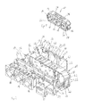
- the presentation of the Fig. 2 shows the device cup 10 of Fig. 1 in an exploded view.
- Fig. 2 It can be seen that the protective contact sockets 18, which form electrical installation devices, are inserted by means of latching hooks into an opening of the cover plate 22. Also, the data socket 20 is provided with latching hooks and inserted by means of these latching hooks in a through hole of the cover plate 24 and latched thereto.
- the interior of the frame 12 is divided by means of a partition wall 28 into two areas, namely on the one hand, the area in which power lines are supplied to the protective contact sockets 18 and on the other hand the area in which data lines of the data box 20 are supplied.
- the cover plates 22, 24 are each provided with resilient latching hooks 30, which are provided with inwardly to the interior of the frame 12 facing out latching hooks. These locking hooks 30 engage when placing the cover plates 22, 24 in groove-like recesses 32 in the circumferential wall of the frame 12 a.
- a width of the latching hook 30 is dimensioned so that it is only slightly smaller than a width of the groove-like recesses 32.
- the side edges of the latching hooks 30 are thereby at least partially against the side walls of the groove-like recesses 32 and thereby stabilize the frame 12 in the latched state considerably.
- the bottom plates 26, 28 are provided with resilient latching hooks 34 which are formed equal to the latching hooks 30 on the cover plates 22, 24. These locking hooks 34 engage in the groove-like recesses 32 and thereby stabilize the frame 12 in the locked state.
- the latching hooks 34 are arranged at the same distance from one another as the latching hooks 30 of the cover plates 22, 24. The bottom plates 26, 28 can thus also be attached to the frame in Fig. 2 front side of the frame 12 are snapped.
- the groove-like recesses 32 each with the outside, so from the interior of the frame 12 pioneering locking lugs 40, 42 are provided.
- the locking lugs 40 are engaged behind by the resilient latching hooks 30 after placing the cover plates 22, 24.
- the locking lugs 42 are engaged behind the touchdown of the bottom plates 26, 28 of the resilient latching hooks 34. Both the cover plates 22, 24 and the bottom plates 26, 28 are thereby securely locked to the frame 12.
- the bottom plates 26, 28 are also placed on the first edge 36 of the frame 12 become.
- the latching hooks 34 of the bottom plates 26, 28 would then engage behind the latching noses 40 in the region of the first edge 36 of the groove-like recesses 32.
- the cover plates 22, 24 could be placed on the second edge 38 of the frame 12.
- the bottom plate 26 has a perforation 54 which is formed by means of three, a first portion 56 and a second portion 58 of the bottom plate 26 connecting webs and intermediate through holes.
- the two sections 56, 58 are connected to each other only by three webs 60, wherein two of the webs are in the region of the side edges of the bottom plate 26, the third web is centered in the bottom plate 26.
- Between two webs 60 are slot-like through holes 62nd
- the portion 56 can now be easily separated from the portion 58 by the bottom plate 26 is bent. As a result, the webs 60 break through.
- either only the section 58, which then the bottom plate 28 in Fig. 2 forms, or only the portion 56 are placed on the frame 12.
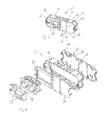
- the presentation of the Fig. 3 shows a device cup 50 according to the invention according to another embodiment of the invention.
- the device cup 50 has a frame 12 which is identical to the frame 12 of the device cup 10 of Fig. 1 and 2 is formed and therefore will not be explained again.
- the frame 12 of the device cup 50 is provided with a cover plate 22 and a total of three bottom plates 26.
- the cover plate 22 serves to accommodate two data-technical installation devices 52.
- two socket outlets 18 are inserted into the cover plate 22.
- the complete underside of the frame 12 is closed by means of two identical cover plates 26. Also the in 3 and 4 right part of the top of the frame 12 is closed by a cover plate 26. An accessibility of the live connections of the Schuko sockets 18 or a back of the data installation equipment 32 is thereby reliably prevented. It should be noted, however, that for the cover of the top of the frame 12, the same bottom plates 26 can be used, which are also provided for closing the underside of the frame 12. As a result of the invention, a device cup which can be used extremely flexibly is thereby created, which, however, manages by means of only a few different individual parts. Specifically, only one type of bottom plate, namely the bottom plate 26, is needed, which is then divided, if necessary, at the predetermined breaking point 54, see Fig. 2 ,
Landscapes
- Engineering & Computer Science (AREA)
- Architecture (AREA)
- Civil Engineering (AREA)
- Structural Engineering (AREA)
- Casings For Electric Apparatus (AREA)
- Connector Housings Or Holding Contact Members (AREA)
- Details Of Indoor Wiring (AREA)
Abstract
Description
- Die Erfindung betrifft einen Gerätebecher für elektrische Installationsgeräte.
- Aus der deutschen Patentschrift
DE 198 45 335 B4 ist ein Gerätebecher für elektrische Installationsgeräte bekannt, der eine trogartige Form mit einem Boden und einer rahmenförmig umlaufenden Wandung aufweist. In der rahmenförmigen Wandung sind nutartige und an die Abmessungen von Rasthaken von Abdeckplatten angepasste Ausnehmungen angeordnet. Abdeckplatten können auf die Oberseite der rahmenförmigen Wandung aufgerastet werden, indem die an den Abdeckplatten angeordneten Rasthaken Rastnasen an der Oberkante der Ausnehmungen hintergreifen. Die Abdeckplatten können Durchgangsöffnungen aufweisen, um elektrische Installationsgeräte zu befestigen. - Aus der deutschen Gebrauchsmusterschrift
DE 20 2011 102 159 U1 ist ein weiterer Gerätebecher zur Aufnahme von Elektroinstallationsgeräten bekannt. Der Gerätebecher besteht aus einem Boden und einer rahmenförmig umlaufenden Wandung. Auf den Gerätebecher wird ein Einbaurahmen aufgerastet, an dem dann elektrische Installationsgeräte befestigt werden können. - Mit der Erfindung soll ein Gerätebecher für elektrische oder datentechnische Installationsgeräte verbessert werden.
- Erfindungsgemäß ist hierzu ein Gerätebecher für elektrische oder datentechnische Installationsgeräte vorgesehen, der einen Rahmen mit einer umlaufenden Wandung mit jeweils wenigstens einem Vorsprung an gegenüberliegenden Enden des Rahmens zum Einhängen des Gerätebechers in Montageöffnungen einer Unterflurkassette aufweist und bei dem wenigstens eine Abdeckplatte zum Aufsetzen auf einen ersten Rand der umlaufenden Wandung vorgesehen ist, wobei die Abdeckplatte wenigstens teilweise mit Befestigungseinrichtungen für Installationsgeräte versehen ist und wobei wenigstens eine Bodenplatte zum Aufsetzen auf einen zweiten, dem ersten Rand gegenüberliegenden Rand der umlaufenden Wandung vorgesehen ist.
- Indem anstelle eines trogartigen Grundkörpers ein Rahmen mit einer umlaufenden Wandung vorgesehen ist, an dessen Unterseite Bodenplatten und an dessen Oberseite Abdeckplatten befestigt werden können, ist es möglich, auch für unterschiedlichste Einbausituationen und Installationsgeräte mit einer vergleichsweise geringen Anzahl an einzelnen Bauteilen auszukommen. Überraschenderweise können die Bodenplatten, der Rahmen und die Abdeckplatten so ausgebildet werden, dass eine ausreichende Stabilität des zusammengebauten Gerätebechers gegeben ist. Beim Einbau von elektrischen Installationsgeräten ist es beispielsweise erforderlich, dass der Gerätebecher einen im Wesentlichen geschlossenen Boden aufweist, um zu verhindern, dass die spannungsführenden Anschlüsse der elektrischen Installationsgeräte zugänglich sind. Bei datentechnischen Installationsgeräten sind hingegen in der Regel nur sehr große Biegeradien der zugeführten Datenleitungen erlaubt, so dass für datentechnische Installationsgeräte die Leitungen bisher durch Öffnungen im Boden des Gerätebechers hindurchgeführt werden mussten. Solche Öffnungen wurden in den Boden hineingebrochen. Alternativ wurde speziell für datentechnische Installationsgeräte mit nach unten hin offenen Befestigungsrahmen gearbeitet. Mit der Erfindung ist es nun möglich, ein und denselben Rahmen mit unterschiedlichen Abdeckplatten und Bodenplatten zu kombinieren und dadurch sowohl für elektrische als auch datentechnische Installationsgeräte jeweils optimale Einbaubedingungen bereitzustellen.
- In Weiterbildung der Erfindung ist eine gegenüber einem Innenraum des Gerätebechers außenliegende Seite der umlaufenden Wandung mit nutartigen Ausnehmungen versehen, die sich vom ersten Rand zum zweiten Rand erstrecken, im Bereich des ersten und des zweiten Rands jeweils mit nach außen gerichteten Rastnasen versehen sind und zum Aufnehmen von federnden Rasthaken der Abdeckplatten bzw. der Bodenplatten dienen.
- Mittels solcher nutartiger Ausnehmungen sowie nach außen gerichteter Rastnasen in den nutartigen Ausnehmungen im Bereich des ersten und zweiten Rands können sowohl Bodenplatten als auch Abdeckplatten sicher befestigt werden. Die Bodenplatten und die Abdeckplatten sind dabei vorteilhafterweise mit Rastnasen versehen, die so in die nutartigen Ausnehmungen eingreifen, dass die Seitenkanten der Rasthaken an den Seitenwänden der nutartigen Ausnehmungen anliegen. Dadurch erhält der Rahmen durch das Aufsetzen der Bodenplatten oder Abdeckplatten eine sehr große Stabilität, die überraschenderweise ausreichend ist, um auch den auf elektrische und datentechnische Installationsgeräte während des Betriebs einwirkenden erheblichen Bedienkräften standzuhalten. Beispielsweise muss in eine Schutzkontaktsteckdose mit Kindersicherung ein Schutzkontaktstecker mit erheblicher Kraft eingesteckt werden, um überhaupt einen Einsteckvorgang zu ermöglichen. Umgekehrt können auch beim Herausziehen der Stecker aus Datensteckdosen oder Energiesteckdosen erhebliche Kräfte auftreten. Die nutartigen Ausnehmungen verlaufen vorteilhafterweise senkrecht zu einer Längsrichtung des Rahmens, wobei die Längsrichtung durch die beiden Vorsprünge an gegenüberliegenden Enden des Rahmens zum Einhängen des Gerätebechers in Montageöffnungen einer Unterflurkassette definiert ist. Auf diese Weise können die Abdeckplatten und/oder die Bodenplatten wahlweise auf eine Oberseite oder Unterseite des Rahmens aufgesetzt werden und können dort jeweils in die durchgehenden nutartigen Ausnehmungen eingreifen.
- In Weiterbildung der Erfindung sind die Abdeckplatten mit Durchgangsöffnungen zum Befestigen von Installationsgeräten versehen.
- Mittels solcher Durchgangsöffnungen, die insbesondere auch mit Rasteinrichtungen versehen sind, können Installationsgeräte zuverlässig, werkzeuglos und schnell befestigt werden.
- In Weiterbildung der Erfindung weist die Bodenplatte wenigstens eine Sollbruchstelle auf, wobei die Sollbruchstelle eine Teilung der Bodenplatte in einer Richtung vom ersten zum zweiten Rand ermöglicht.
- Durch Vorsehen wenigstens einer Sollbruchstelle können die Bodenplatten bei Bedarf verkleinert werden. Beispielsweise dann, wenn in einem Teilbereich des Gerätebechers ein datentechnisches Installationsgerät angeordnet werden soll, kann in diesem Bereich die Bodenplatte abgebrochen werden, um das Zuführen von Datenleitungen im großen Radius zu ermöglichen. Dies deshalb, da die Unterseite des Gerätebechers dann offen ist.
- In Weiterbildung der Erfindung ist die Sollbruchstelle als Perforation ausgebildet.
- In Weiterbildung der Erfindung sind die Bodenplatte und die umlaufende Wandung so ausgebildet, dass die Bodenplatte sowohl auf den ersten Rand als auch den zweiten Rand der umlaufenden Wandung aufgesetzt werden kann.
- Auf diese Weise ist es möglich, die Bodenplatten auch zum Abdecken einer Oberseite des Rahmens zu verwenden, beispielsweise wenn in einem Gerätebecher lediglich wenige Installationsgeräte angeordnet werden sollen. Mittels der Bodenplatten kann dann auch die Oberseite des Rahmens benachbart zu den Installationsgeräten verschlossen werden und es wird keine speziell ausgebildete Abdeckplatte benötigt.
- Weitere Merkmale und Vorteile der Erfindung ergeben sich aus den Ansprüchen und der folgenden Beschreibung bevorzugter Ausführungsformen der Erfindung im Zusammenhang mit den Zeichnungen. Einzelmerkmale der unterschiedlichen, in den Zeichnungen dargestellten und der Beschreibung beschriebenen Ausführungsformen lassen sich dabei in beliebiger Weise miteinander kombinieren, ohne den Rahmen der Erfindung zu überschreiten. In den Zeichnungen zeigen:
- Fig. 1
- einen erfindungsgemäßen Gerätebecher gemäß einer ersten Ausführungsform mit elektrischen und datentechnischen Installationsgeräten,
- Fig. 2
- den Gerätebecher der
Fig. 1 in auseinandergezogener Darstellung, - Fig. 3
- einen erfindungsgemäßen Gerätebecher gemäß einer weiteren Ausführungsform und
- Fig. 4
- den Gerätebecher der
Fig. 3 in auseinandergezogener Darstellung. - In
Fig. 1 ist in einer Ansicht von schräg oben ein erfindungsgemäßer Gerätebecher 10 dargestellt, der einen Rahmen 12 mit umlaufender Wandung aufweist. An dem Rahmen ist an gegenüberliegenden Enden jeweils ein Vorsprung 14 bzw. 16 angeordnet, der zum Einhängen des Gerätebechers in Rastleitern einer nicht dargestellten Unterflurkassette dient. In den Gerätebecher sind drei Schutzkontaktsteckdosen 18 eingesetzt sowie eine Datendose 20. Die Schutzkontaktsteckdosen 18 sind wiederum an einer Abdeckplatte 22 befestigt, die auf den Rahmen 12 aufgesetzt ist. Auch die Datendose 20 ist an einer Abdeckplatte 24 befestigt, die ebenfalls auf den Rahmen 12 aufgesetzt ist. - Auf einer, den Abdeckplatten 22, 24 gegenüberliegenden Seite des Rahmens 12 sind Bodenplatten 26, 28 aufgesetzt, die die Unterseite des Rahmens 12 teilweise verschließen. Unterhalb der Datendose 20 ist der Rahmen 12 offen, um die zu der Datendose 20 führenden Datenleitungen in möglichst großem Radius in den Gerätebecher 10 einführen zu können.
- Die Darstellung der
Fig. 2 zeigt den Gerätebecher 10 derFig. 1 in auseinandergezogener Darstellung. - In
Fig. 2 ist zu erkennen, dass die Schutzkontaktsteckdosen 18, die elektrische Installationsgeräte bilden, mittels Rasthaken in eine Öffnung der Abdeckplatte 22 eingesetzt sind. Auch die Datendose 20 ist mit Rasthaken versehen und mittels dieser Rasthaken in eine Durchgangsöffnung der Abdeckplatte 24 eingesetzt und an dieser verrastet. - Der Innenraum des Rahmens 12 wird mittels einer Trennwand 28 in zwei Bereiche unterteilt, nämlich zum einen den Bereich, in dem Energieleitungen den Schutzkontaktsteckdosen 18 zugeführt werden und zum anderen den Bereich, in dem Datenleitungen der Datendose 20 zugeführt werden.
- Die Abdeckplatten 22, 24 sind jeweils mit federnden Rasthaken 30 versehen, die mit nach innen, zum Innenraum des Rahmens 12 hin weisenden Rasthaken versehen sind. Diese Rasthaken 30 greifen beim Aufsetzen der Abdeckplatten 22, 24 in nutartige Ausnehmungen 32 in der umlaufenden Wandung des Rahmens 12 ein. Eine Breite der Rasthaken 30 ist dabei so bemessen, dass diese nur geringfügig kleiner ist als eine Breite der nutartigen Ausnehmungen 32. Die Seitenkanten der Rasthaken 30 liegen dadurch wenigstens abschnittsweise an den Seitenwänden der nutartigen Ausnehmungen 32 an und stabilisieren im verrasteten Zustand dadurch den Rahmen 12 erheblich.
- Auch die Bodenplatten 26, 28 sind mit federnden Rasthaken 34 versehen, die gleich zu den Rasthaken 30 an den Abdeckplatten 22, 24 ausgebildet sind. Auch diese Rasthaken 34 greifen in die nutartigen Ausnehmungen 32 ein und stabilisieren dadurch im verrasteten Zustand den Rahmen 12. Die Rasthaken 34 sind im gleichen Abstand zueinander angeordnet wie die Rasthaken 30 der Abdeckplatten 22, 24. Auch die Bodenplatten 26, 28 können somit an der in
Fig. 2 vorne liegenden Seite des Rahmens 12 aufgerastet werden. - Im Bereich eines in
Fig. 2 vorne liegenden ersten Randes 36 des Rahmens 12 sowie auch im Bereich des gegenüberliegenden zweiten Randes 38 des Rahmens 12 sind die nutartigen Ausnehmungen 32 jeweils mit außen, also vom Innenraum des Rahmens 12 wegweisenden Rastnasen 40, 42 versehen. Die Rastnasen 40 werden nach dem Aufsetzen der Abdeckplatten 22, 24 von den federnden Rasthaken 30 hintergriffen. Die Rastnasen 42 werden nach dem Aufsetzen der Bodenplatten 26, 28 von den federnden Rasthaken 34 hintergriffen. Sowohl die Abdeckplatten 22, 24 als auch die Bodenplatten 26, 28 sind dadurch sicher an dem Rahmen 12 verrastet. Da die nutartigen Ausnehmungen 32 senkrecht zu einer Längsrichtung des Rahmens 12 verlaufen, wobei sich diese Längsrichtung zwischen den beiden Vorsprüngen 14, 16 an den gegenüberliegenden Enden des Rahmens 12 erstreckt, können die Bodenplatten 26, 28 auch auf den ersten Rand 36 des Rahmens 12 aufgesetzt werden. Die Rasthaken 34 der Bodenplatten 26, 28 würden dann die Rastnasen 40 im Bereich des ersten Rands 36 der nutartigen Ausnehmungen 32 hintergreifen. In gleicher Weise könnten, falls dies als erforderlich angesehen wird, die Abdeckplatten 22, 24 auf den zweiten Rand 38 des Rahmens 12 aufgesetzt werden. - Anhand der
Fig. 2 ist noch zu erkennen, dass die Bodenplatte 26 eine Perforation 54 aufweist, die mittels dreier, einen ersten Abschnitt 56 und einen zweiten Abschnitt 58 der Bodenplatte 26 verbindender Stege und dazwischenliegender Durchgangsöffnungen ausbildet ist. Gut zu erkennen sind die beiden Abschnitte 58 und 56 der Bodenplatte 26 inFig. 3 . Wie ausgeführt, sind die beiden Abschnitte 56, 58 lediglich durch drei Stege 60 miteinander verbunden, wobei zwei der Stege im Bereich der Seitenkanten der Bodenplatte 26 liegen, der dritte Steg liegt mittig in der Bodenplatte 26. Zwischen jeweils zwei Stegen 60 liegen schlitzartige Durchgangsöffnungen 62. Der Abschnitt 56 kann nun in einfacher Weise vom Abschnitt 58 getrennt werden, indem die Bodenplatte 26 abgeknickt wird. Dadurch brechen die Stege 60 durch. Wahlweise kann dann entweder nur der Abschnitt 58, der dann die Bodenplatte 28 inFig. 2 bildet, oder nur der Abschnitt 56 auf den Rahmen 12 aufgesetzt werden. - Auch auf diese Weise kann die Anzahl der Einzelteile für den erfindungsgemäßen Gerätebecher verringert werden.
- Die Darstellung der
Fig. 3 zeigt einen erfindungsgemäßen Gerätebecher 50 gemäß einer weiteren Ausführungsform der Erfindung. - Der Gerätebecher 50 weist einen Rahmen 12 auf, der identisch zu dem Rahmen 12 des Gerätebechers 10 der
Fig. 1 und 2 ausgebildet ist und daher nicht erneut erläutert wird. Im Unterschied zu dem Gerätebecher 10 derFig. 1 und 2 ist der Rahmen 12 des Gerätebechers 50 mit einer Abdeckplatte 22 und insgesamt drei Bodenplatten 26 versehen. Die Abdeckplatte 22 dient zur Aufnahme zweier datentechnischer Installationsgeräte 52. Alternativ können, wie inFig. 4 dargestellt ist, anstelle der datentechnischen Installationsgeräte 52 auch zwei Schutzkontaktsteckdosen 18 in die Abdeckplatte 22 eingesetzt werden. - Die vollständige Unterseite des Rahmens 12 ist mittels zweier identischer Abdeckplatten 26 verschlossen. Auch der in
Fig. 3 und 4 rechte Teil der Oberseite des Rahmens 12 ist mit einer Abdeckplatte 26 verschlossen. Eine Zugänglichkeit der spannungsführenden Anschlüsse der Schutzkontaktsteckdosen 18 oder auch einer Rückseite der datentechnischen Installationsgeräte 32 ist dadurch zuverlässig verhindert. Dabei ist aber festzustellen, dass auch für die Abdeckung der Oberseite des Rahmens 12 dieselben Bodenplatten 26 verwendet werden können, die auch für das Verschließen der Unterseite des Rahmens 12 vorgesehen sind. Durch die Erfindung wird dadurch ein äußerst flexibel einzusetzender Gerätebecher geschaffen, der aber mittels nur weniger unterschiedlicher Einzelteile auskommt. Speziell wird nur eine Art Bodenplatte, nämlich die Bodenplatte 26, benötigt, die dann, falls erforderlich, an der Sollbruchstelle 54 geteilt wird, sieheFig. 2 .
Claims (6)
- Gerätebecher für elektrische oder datentechnische Installationsgeräte gekennzeichnet durch einen Rahmen (12) mit einer umlaufenden Wandung und mit jeweils wenigstens einem Vorsprung (14, 16) an gegenüberliegenden Enden des Rahmens (12) zum Einhängen des Gerätebechers (10, 50) in Montageöffnungen einer Unterflurkassette, wobei wenigstens eine Abdeckplatte (22, 24) zum Aufsetzen auf einen ersten Rand (36) der umlaufenden Wandung vorgesehen ist, wobei die Abdeckplatte (22, 24) wenigstens teilweise mit Befestigungseinrichtungen für Installationsgeräte versehen ist und wobei wenigstens eine Bodenplatte (26, 28) zum Aufsetzen auf einen zweiten, dem ersten Rand (36) gegenüberliegenden Rand (38) der umlaufenden Wandung vorgesehen ist.
- Gerätebecher nach Anspruch 1, dadurch gekennzeichnet, dass eine gegenüber einem Innenraum des Gerätebechers (10, 50) außenliegende Seite der umlaufenden Wandung mit nutartigen Ausnehmungen (32) versehen ist, die sich vom ersten Rand (36) zum zweiten Rand (38) erstrecken, im Bereich des ersten und des zweiten Randes (36) jeweils mit nach außen gerichteten Rastnasen (40, 42) versehen sind und zum wenigstens abschnittsweisen Aufnehmen von federnden Rasthaken (30, 34) der Abdeckplatten (22, 24) beziehungsweise der Bodenplatten (26, 28) dienen.
- Gerätebecher nach Anspruch 1 oder 2, dadurch gekennzeichnet, dass die Abdeckplatten (22, 24) mit Durchgangsöffnungen zum Befestigen von Installationsgeräten versehen ist.
- Gerätebecher nach wenigstens einem der vorstehenden Ansprüche, dadurch gekennzeichnet, dass die Bodenplatte (26) wenigstens eine Sollbruchstelle (54) aufweist, wobei die Sollbruchstelle (54) eine Teilung der Bodenplatte (26) ermöglicht.
- Gerätebecher nach Anspruch 4, dadurch gekennzeichnet, dass die Sollbruchstelle (54) als Perforation ausgebildet ist.
- Gerätebecher nach wenigstens einem der vorstehenden Ansprüche, dadurch gekennzeichnet, dass die Bodenplatte (26, 28) und die umlaufende Wandung so ausgebildet sind, dass die Bodenplatte (26, 28) sowohl auf den ersten Rand (36) als auch den zweiten Rand (38) der umlaufenden Wandung aufgesetzt werden kann.
Priority Applications (1)
| Application Number | Priority Date | Filing Date | Title |
|---|---|---|---|
| PL15166735T PL2953221T3 (pl) | 2014-06-06 | 2015-05-07 | Puszka instalacyjna do elektrycznych urządzeń instalacyjnych |
Applications Claiming Priority (1)
| Application Number | Priority Date | Filing Date | Title |
|---|---|---|---|
| DE102014210948.5A DE102014210948B4 (de) | 2014-06-06 | 2014-06-06 | Gerätebecher für elektrische Installationsgeräte |
Publications (2)
| Publication Number | Publication Date |
|---|---|
| EP2953221A1 true EP2953221A1 (de) | 2015-12-09 |
| EP2953221B1 EP2953221B1 (de) | 2020-08-19 |
Family
ID=53054934
Family Applications (1)
| Application Number | Title | Priority Date | Filing Date |
|---|---|---|---|
| EP15166735.9A Active EP2953221B1 (de) | 2014-06-06 | 2015-05-07 | Gerätebecher für elektrische installationsgeräte |
Country Status (6)
| Country | Link |
|---|---|
| EP (1) | EP2953221B1 (de) |
| DE (1) | DE102014210948B4 (de) |
| ES (1) | ES2828449T3 (de) |
| HU (1) | HUE051304T2 (de) |
| PL (1) | PL2953221T3 (de) |
| PT (1) | PT2953221T (de) |
Citations (4)
| Publication number | Priority date | Publication date | Assignee | Title |
|---|---|---|---|---|
| EP0991158A1 (de) * | 1998-10-01 | 2000-04-05 | Albert Ackermann GmbH & Co. KG | Geräteaufnahme für eine Unterflurgerätedose |
| DE202006010817U1 (de) * | 2006-04-26 | 2007-08-30 | Vergokan N.V. | Zugentlastung für Gerätebecher |
| DE102008015770A1 (de) * | 2008-03-26 | 2009-10-22 | Electraplan Solutions Gmbh | Versorgungseinheit für Unterfluranwendung |
| DE202011102159U1 (de) | 2011-06-22 | 2012-09-24 | Tehalit Gmbh | Gerätebecher für Unterflur-Elektroinstallationen |
-
2014
- 2014-06-06 DE DE102014210948.5A patent/DE102014210948B4/de active Active
-
2015
- 2015-05-07 PT PT151667359T patent/PT2953221T/pt unknown
- 2015-05-07 PL PL15166735T patent/PL2953221T3/pl unknown
- 2015-05-07 EP EP15166735.9A patent/EP2953221B1/de active Active
- 2015-05-07 ES ES15166735T patent/ES2828449T3/es active Active
- 2015-05-07 HU HUE15166735A patent/HUE051304T2/hu unknown
Patent Citations (5)
| Publication number | Priority date | Publication date | Assignee | Title |
|---|---|---|---|---|
| EP0991158A1 (de) * | 1998-10-01 | 2000-04-05 | Albert Ackermann GmbH & Co. KG | Geräteaufnahme für eine Unterflurgerätedose |
| DE19845335B4 (de) | 1998-10-01 | 2008-05-21 | Obo Bettermann Gmbh & Co. Kg | Geräteaufnahme für eine Unterflurgerätedose |
| DE202006010817U1 (de) * | 2006-04-26 | 2007-08-30 | Vergokan N.V. | Zugentlastung für Gerätebecher |
| DE102008015770A1 (de) * | 2008-03-26 | 2009-10-22 | Electraplan Solutions Gmbh | Versorgungseinheit für Unterfluranwendung |
| DE202011102159U1 (de) | 2011-06-22 | 2012-09-24 | Tehalit Gmbh | Gerätebecher für Unterflur-Elektroinstallationen |
Also Published As
| Publication number | Publication date |
|---|---|
| PL2953221T3 (pl) | 2021-02-08 |
| ES2828449T3 (es) | 2021-05-26 |
| HUE051304T2 (hu) | 2021-03-01 |
| DE102014210948B4 (de) | 2022-07-28 |
| DE102014210948A1 (de) | 2015-12-17 |
| EP2953221B1 (de) | 2020-08-19 |
| PT2953221T (pt) | 2020-10-19 |
Similar Documents
| Publication | Publication Date | Title |
|---|---|---|
| DE102011002135B4 (de) | Steckerelement mit zweiter Kontaktsicherung | |
| EP2012390B1 (de) | Erdungsklammer zum Potentialausgleich von Leitungsführungskanälen | |
| EP3016215A1 (de) | Erdungsschienenvorrichtung | |
| EP2858186B1 (de) | Sammelschienen-Adapter | |
| DE102008060808B4 (de) | Bodeneinbaukassette für elektrische Installationsgeräte | |
| EP2806516A1 (de) | Dichtblock für Einzeladern | |
| EP2953221B1 (de) | Gerätebecher für elektrische installationsgeräte | |
| DE102024100111A1 (de) | Zähler- und Verteilerschrank | |
| EP2538510B1 (de) | Gerätebecher für Unterflur-Elektroinstallationen | |
| EP3136524B1 (de) | Erdungsmutternkette | |
| DE102006015317A1 (de) | Geräteeinbausatz zur Anordnung eines Gerätes in einer elektrischen Schaltanlage | |
| EP2019458A2 (de) | Steckdose, insbesondere Anhänger-Steckdose | |
| EP1480309B1 (de) | Stopfen zum Verschliessen einer in einem Gehäuse vorgesehenen Öffnung zur Durchführung von Kabeln | |
| EP2418746A2 (de) | Gerätedose für Installationsgeräte | |
| EP2639912B1 (de) | Geräteeinbaudose für Geräteeinbaukanäle sowie diese umfassender Geräteeinbaukanal | |
| WO2013143930A1 (de) | Systemmodul für die gebäude-elektroinstallationstechnik und türkommunikationstechnik | |
| DE102009009500A1 (de) | Gehäuse | |
| DE202006010818U1 (de) | Gerätebecher | |
| DE102017112519B4 (de) | Haushaltsgerät | |
| EP3558058B1 (de) | Möbel mit kabeldurchführung und verfahren zum ausbilden einer kabeldurchführung | |
| DE9106787U1 (de) | Elektrodose | |
| DE102016225550A1 (de) | Gehäuseanordnung mit Leiterplattenhalter | |
| EP2876757B1 (de) | Rahmenartiger Montageadapter, Sortiment von rahmenartigen Montageadaptern und Einrichtung mit einem Gerätegehäuse und wenigstens einem rahmenartigen Montageadapter | |
| DE1490324C (de) | Im wesentlichen quaderförmiges Gehäuse für einzelne Geräte der Elektrotechnik | |
| DE1189185B (de) | Elektrische Sicherungsdose |
Legal Events
| Date | Code | Title | Description |
|---|---|---|---|
| PUAI | Public reference made under article 153(3) epc to a published international application that has entered the european phase |
Free format text: ORIGINAL CODE: 0009012 |
|
| AK | Designated contracting states |
Kind code of ref document: A1 Designated state(s): AL AT BE BG CH CY CZ DE DK EE ES FI FR GB GR HR HU IE IS IT LI LT LU LV MC MK MT NL NO PL PT RO RS SE SI SK SM TR |
|
| AX | Request for extension of the european patent |
Extension state: BA ME |
|
| 17P | Request for examination filed |
Effective date: 20160607 |
|
| RBV | Designated contracting states (corrected) |
Designated state(s): AL AT BE BG CH CY CZ DE DK EE ES FI FR GB GR HR HU IE IS IT LI LT LU LV MC MK MT NL NO PL PT RO RS SE SI SK SM TR |
|
| STAA | Information on the status of an ep patent application or granted ep patent |
Free format text: STATUS: EXAMINATION IS IN PROGRESS |
|
| 17Q | First examination report despatched |
Effective date: 20180227 |
|
| RIC1 | Information provided on ipc code assigned before grant |
Ipc: H02G 3/08 20060101ALI20200409BHEP Ipc: H02G 3/14 20060101ALN20200409BHEP Ipc: H02G 3/18 20060101AFI20200409BHEP |
|
| GRAP | Despatch of communication of intention to grant a patent |
Free format text: ORIGINAL CODE: EPIDOSNIGR1 |
|
| STAA | Information on the status of an ep patent application or granted ep patent |
Free format text: STATUS: GRANT OF PATENT IS INTENDED |
|
| INTG | Intention to grant announced |
Effective date: 20200519 |
|
| GRAS | Grant fee paid |
Free format text: ORIGINAL CODE: EPIDOSNIGR3 |
|
| GRAA | (expected) grant |
Free format text: ORIGINAL CODE: 0009210 |
|
| STAA | Information on the status of an ep patent application or granted ep patent |
Free format text: STATUS: THE PATENT HAS BEEN GRANTED |
|
| AK | Designated contracting states |
Kind code of ref document: B1 Designated state(s): AL AT BE BG CH CY CZ DE DK EE ES FI FR GB GR HR HU IE IS IT LI LT LU LV MC MK MT NL NO PL PT RO RS SE SI SK SM TR |
|
| REG | Reference to a national code |
Ref country code: CH Ref legal event code: EP |
|
| REG | Reference to a national code |
Ref country code: DE Ref legal event code: R096 Ref document number: 502015013256 Country of ref document: DE |
|
| REG | Reference to a national code |
Ref country code: AT Ref legal event code: REF Ref document number: 1305045 Country of ref document: AT Kind code of ref document: T Effective date: 20200915 |
|
| REG | Reference to a national code |
Ref country code: IE Ref legal event code: FG4D Free format text: LANGUAGE OF EP DOCUMENT: GERMAN |
|
| REG | Reference to a national code |
Ref country code: PT Ref legal event code: SC4A Ref document number: 2953221 Country of ref document: PT Date of ref document: 20201019 Kind code of ref document: T Free format text: AVAILABILITY OF NATIONAL TRANSLATION Effective date: 20201012 |
|
| REG | Reference to a national code |
Ref country code: FI Ref legal event code: FGE |
|
| REG | Reference to a national code |
Ref country code: NL Ref legal event code: FP |
|
| REG | Reference to a national code |
Ref country code: LT Ref legal event code: MG4D |
|
| PG25 | Lapsed in a contracting state [announced via postgrant information from national office to epo] |
Ref country code: SE Free format text: LAPSE BECAUSE OF FAILURE TO SUBMIT A TRANSLATION OF THE DESCRIPTION OR TO PAY THE FEE WITHIN THE PRESCRIBED TIME-LIMIT Effective date: 20200819 Ref country code: NO Free format text: LAPSE BECAUSE OF FAILURE TO SUBMIT A TRANSLATION OF THE DESCRIPTION OR TO PAY THE FEE WITHIN THE PRESCRIBED TIME-LIMIT Effective date: 20201119 Ref country code: HR Free format text: LAPSE BECAUSE OF FAILURE TO SUBMIT A TRANSLATION OF THE DESCRIPTION OR TO PAY THE FEE WITHIN THE PRESCRIBED TIME-LIMIT Effective date: 20200819 Ref country code: BG Free format text: LAPSE BECAUSE OF FAILURE TO SUBMIT A TRANSLATION OF THE DESCRIPTION OR TO PAY THE FEE WITHIN THE PRESCRIBED TIME-LIMIT Effective date: 20201119 Ref country code: GR Free format text: LAPSE BECAUSE OF FAILURE TO SUBMIT A TRANSLATION OF THE DESCRIPTION OR TO PAY THE FEE WITHIN THE PRESCRIBED TIME-LIMIT Effective date: 20201120 Ref country code: LT Free format text: LAPSE BECAUSE OF FAILURE TO SUBMIT A TRANSLATION OF THE DESCRIPTION OR TO PAY THE FEE WITHIN THE PRESCRIBED TIME-LIMIT Effective date: 20200819 |
|
| PG25 | Lapsed in a contracting state [announced via postgrant information from national office to epo] |
Ref country code: LV Free format text: LAPSE BECAUSE OF FAILURE TO SUBMIT A TRANSLATION OF THE DESCRIPTION OR TO PAY THE FEE WITHIN THE PRESCRIBED TIME-LIMIT Effective date: 20200819 Ref country code: RS Free format text: LAPSE BECAUSE OF FAILURE TO SUBMIT A TRANSLATION OF THE DESCRIPTION OR TO PAY THE FEE WITHIN THE PRESCRIBED TIME-LIMIT Effective date: 20200819 Ref country code: IS Free format text: LAPSE BECAUSE OF FAILURE TO SUBMIT A TRANSLATION OF THE DESCRIPTION OR TO PAY THE FEE WITHIN THE PRESCRIBED TIME-LIMIT Effective date: 20201219 |
|
| REG | Reference to a national code |
Ref country code: HU Ref legal event code: AG4A Ref document number: E051304 Country of ref document: HU |
|
| PG25 | Lapsed in a contracting state [announced via postgrant information from national office to epo] |
Ref country code: EE Free format text: LAPSE BECAUSE OF FAILURE TO SUBMIT A TRANSLATION OF THE DESCRIPTION OR TO PAY THE FEE WITHIN THE PRESCRIBED TIME-LIMIT Effective date: 20200819 Ref country code: SM Free format text: LAPSE BECAUSE OF FAILURE TO SUBMIT A TRANSLATION OF THE DESCRIPTION OR TO PAY THE FEE WITHIN THE PRESCRIBED TIME-LIMIT Effective date: 20200819 Ref country code: RO Free format text: LAPSE BECAUSE OF FAILURE TO SUBMIT A TRANSLATION OF THE DESCRIPTION OR TO PAY THE FEE WITHIN THE PRESCRIBED TIME-LIMIT Effective date: 20200819 Ref country code: DK Free format text: LAPSE BECAUSE OF FAILURE TO SUBMIT A TRANSLATION OF THE DESCRIPTION OR TO PAY THE FEE WITHIN THE PRESCRIBED TIME-LIMIT Effective date: 20200819 Ref country code: CZ Free format text: LAPSE BECAUSE OF FAILURE TO SUBMIT A TRANSLATION OF THE DESCRIPTION OR TO PAY THE FEE WITHIN THE PRESCRIBED TIME-LIMIT Effective date: 20200819 |
|
| REG | Reference to a national code |
Ref country code: DE Ref legal event code: R097 Ref document number: 502015013256 Country of ref document: DE |
|
| REG | Reference to a national code |
Ref country code: ES Ref legal event code: FG2A Ref document number: 2828449 Country of ref document: ES Kind code of ref document: T3 Effective date: 20210526 |
|
| PG25 | Lapsed in a contracting state [announced via postgrant information from national office to epo] |
Ref country code: AL Free format text: LAPSE BECAUSE OF FAILURE TO SUBMIT A TRANSLATION OF THE DESCRIPTION OR TO PAY THE FEE WITHIN THE PRESCRIBED TIME-LIMIT Effective date: 20200819 |
|
| PLBE | No opposition filed within time limit |
Free format text: ORIGINAL CODE: 0009261 |
|
| STAA | Information on the status of an ep patent application or granted ep patent |
Free format text: STATUS: NO OPPOSITION FILED WITHIN TIME LIMIT |
|
| PG25 | Lapsed in a contracting state [announced via postgrant information from national office to epo] |
Ref country code: SK Free format text: LAPSE BECAUSE OF FAILURE TO SUBMIT A TRANSLATION OF THE DESCRIPTION OR TO PAY THE FEE WITHIN THE PRESCRIBED TIME-LIMIT Effective date: 20200819 |
|
| 26N | No opposition filed |
Effective date: 20210520 |
|
| PG25 | Lapsed in a contracting state [announced via postgrant information from national office to epo] |
Ref country code: IT Free format text: LAPSE BECAUSE OF FAILURE TO SUBMIT A TRANSLATION OF THE DESCRIPTION OR TO PAY THE FEE WITHIN THE PRESCRIBED TIME-LIMIT Effective date: 20200819 |
|
| PG25 | Lapsed in a contracting state [announced via postgrant information from national office to epo] |
Ref country code: SI Free format text: LAPSE BECAUSE OF FAILURE TO SUBMIT A TRANSLATION OF THE DESCRIPTION OR TO PAY THE FEE WITHIN THE PRESCRIBED TIME-LIMIT Effective date: 20200819 |
|
| REG | Reference to a national code |
Ref country code: CH Ref legal event code: PL |
|
| GBPC | Gb: european patent ceased through non-payment of renewal fee |
Effective date: 20210507 |
|
| PG25 | Lapsed in a contracting state [announced via postgrant information from national office to epo] |
Ref country code: LI Free format text: LAPSE BECAUSE OF NON-PAYMENT OF DUE FEES Effective date: 20210531 Ref country code: MC Free format text: LAPSE BECAUSE OF FAILURE TO SUBMIT A TRANSLATION OF THE DESCRIPTION OR TO PAY THE FEE WITHIN THE PRESCRIBED TIME-LIMIT Effective date: 20200819 Ref country code: LU Free format text: LAPSE BECAUSE OF NON-PAYMENT OF DUE FEES Effective date: 20210507 Ref country code: CH Free format text: LAPSE BECAUSE OF NON-PAYMENT OF DUE FEES Effective date: 20210531 |
|
| PG25 | Lapsed in a contracting state [announced via postgrant information from national office to epo] |
Ref country code: IE Free format text: LAPSE BECAUSE OF NON-PAYMENT OF DUE FEES Effective date: 20210507 Ref country code: GB Free format text: LAPSE BECAUSE OF NON-PAYMENT OF DUE FEES Effective date: 20210507 |
|
| PG25 | Lapsed in a contracting state [announced via postgrant information from national office to epo] |
Ref country code: CY Free format text: LAPSE BECAUSE OF FAILURE TO SUBMIT A TRANSLATION OF THE DESCRIPTION OR TO PAY THE FEE WITHIN THE PRESCRIBED TIME-LIMIT Effective date: 20200819 |
|
| P01 | Opt-out of the competence of the unified patent court (upc) registered |
Effective date: 20230525 |
|
| PG25 | Lapsed in a contracting state [announced via postgrant information from national office to epo] |
Ref country code: MK Free format text: LAPSE BECAUSE OF FAILURE TO SUBMIT A TRANSLATION OF THE DESCRIPTION OR TO PAY THE FEE WITHIN THE PRESCRIBED TIME-LIMIT Effective date: 20200819 |
|
| PG25 | Lapsed in a contracting state [announced via postgrant information from national office to epo] |
Ref country code: TR Free format text: LAPSE BECAUSE OF FAILURE TO SUBMIT A TRANSLATION OF THE DESCRIPTION OR TO PAY THE FEE WITHIN THE PRESCRIBED TIME-LIMIT Effective date: 20200819 |
|
| PGFP | Annual fee paid to national office [announced via postgrant information from national office to epo] |
Ref country code: ES Payment date: 20240614 Year of fee payment: 10 |
|
| PGFP | Annual fee paid to national office [announced via postgrant information from national office to epo] |
Ref country code: FI Payment date: 20240521 Year of fee payment: 10 |
|
| PGFP | Annual fee paid to national office [announced via postgrant information from national office to epo] |
Ref country code: PL Payment date: 20240415 Year of fee payment: 10 |
|
| PG25 | Lapsed in a contracting state [announced via postgrant information from national office to epo] |
Ref country code: MT Free format text: LAPSE BECAUSE OF FAILURE TO SUBMIT A TRANSLATION OF THE DESCRIPTION OR TO PAY THE FEE WITHIN THE PRESCRIBED TIME-LIMIT Effective date: 20200819 |
|
| PGFP | Annual fee paid to national office [announced via postgrant information from national office to epo] |
Ref country code: NL Payment date: 20250522 Year of fee payment: 11 |
|
| PGFP | Annual fee paid to national office [announced via postgrant information from national office to epo] |
Ref country code: DE Payment date: 20250521 Year of fee payment: 11 |
|
| PGFP | Annual fee paid to national office [announced via postgrant information from national office to epo] |
Ref country code: BE Payment date: 20250520 Year of fee payment: 11 |
|
| PGFP | Annual fee paid to national office [announced via postgrant information from national office to epo] |
Ref country code: PT Payment date: 20250507 Year of fee payment: 11 |
|
| PGFP | Annual fee paid to national office [announced via postgrant information from national office to epo] |
Ref country code: FR Payment date: 20250521 Year of fee payment: 11 Ref country code: HU Payment date: 20250505 Year of fee payment: 11 |
|
| PGFP | Annual fee paid to national office [announced via postgrant information from national office to epo] |
Ref country code: AT Payment date: 20250519 Year of fee payment: 11 |
|
| PG25 | Lapsed in a contracting state [announced via postgrant information from national office to epo] |
Ref country code: FI Free format text: LAPSE BECAUSE OF NON-PAYMENT OF DUE FEES Effective date: 20250507 |