EP2953221A1 - Panier de support d'appareillages pour appareils d'installation électriques - Google Patents
Panier de support d'appareillages pour appareils d'installation électriques Download PDFInfo
- Publication number
- EP2953221A1 EP2953221A1 EP15166735.9A EP15166735A EP2953221A1 EP 2953221 A1 EP2953221 A1 EP 2953221A1 EP 15166735 A EP15166735 A EP 15166735A EP 2953221 A1 EP2953221 A1 EP 2953221A1
- Authority
- EP
- European Patent Office
- Prior art keywords
- edge
- frame
- device cup
- bottom plate
- peripheral wall
- Prior art date
- Legal status (The legal status is an assumption and is not a legal conclusion. Google has not performed a legal analysis and makes no representation as to the accuracy of the status listed.)
- Granted
Links
Images
Classifications
-
- H—ELECTRICITY
- H02—GENERATION; CONVERSION OR DISTRIBUTION OF ELECTRIC POWER
- H02G—INSTALLATION OF ELECTRIC CABLES OR LINES, OR OF COMBINED OPTICAL AND ELECTRIC CABLES OR LINES
- H02G3/00—Installations of electric cables or lines or protective tubing therefor in or on buildings, equivalent structures or vehicles
- H02G3/02—Details
- H02G3/08—Distribution boxes; Connection or junction boxes
- H02G3/18—Distribution boxes; Connection or junction boxes providing line outlets
- H02G3/185—Floor outlets and access cups
-
- H—ELECTRICITY
- H02—GENERATION; CONVERSION OR DISTRIBUTION OF ELECTRIC POWER
- H02G—INSTALLATION OF ELECTRIC CABLES OR LINES, OR OF COMBINED OPTICAL AND ELECTRIC CABLES OR LINES
- H02G3/00—Installations of electric cables or lines or protective tubing therefor in or on buildings, equivalent structures or vehicles
- H02G3/02—Details
- H02G3/08—Distribution boxes; Connection or junction boxes
- H02G3/086—Assembled boxes
-
- H—ELECTRICITY
- H02—GENERATION; CONVERSION OR DISTRIBUTION OF ELECTRIC POWER
- H02G—INSTALLATION OF ELECTRIC CABLES OR LINES, OR OF COMBINED OPTICAL AND ELECTRIC CABLES OR LINES
- H02G3/00—Installations of electric cables or lines or protective tubing therefor in or on buildings, equivalent structures or vehicles
- H02G3/02—Details
- H02G3/08—Distribution boxes; Connection or junction boxes
- H02G3/14—Fastening of cover or lid to box
Definitions
- the invention relates to a device cup for electrical installation equipment.
- a device cup for electrical installation equipment which has a trough-like shape with a bottom and a frame-shaped circumferential wall.
- the frame-shaped wall groove-like and adapted to the dimensions of latching hooks of cover plates recesses are arranged.
- Cover plates can be snapped onto the top of the frame-shaped wall by the latching hooks arranged on the cover plates engage behind latching lugs on the upper edge of the recesses.
- the cover plates may have through holes to secure electrical installation equipment.
- the device cup for receiving electrical installation equipment is known.
- the device cup consists of a bottom and a frame-shaped encircling wall. On the device cup a mounting frame is snapped on the then electrical installation equipment can be attached.
- a device cup for electrical or data-technical installation equipment for this purpose, which has a frame with a circumferential wall, each with at least one projection at opposite ends of the frame for mounting the device cup in mounting holes of an underfloor cassette and at least one cover plate for placing on a first edge the peripheral wall is provided, wherein the cover plate is at least partially provided with fastening means for installation devices and wherein at least one bottom plate for placement on a second, the first edge opposite edge of the peripheral wall is provided.
- a frame is provided with a circumferential wall, on the underside of floor panels and on the top cover plates can be attached, it is possible to make do with a comparatively small number of individual components, even for a wide variety of installation situations and installation equipment.
- the bottom plates, the frame and the cover plates so be formed that sufficient stability of the assembled device cup is given.
- an outer side of the peripheral wall is provided with groove-like recesses extending from the first edge to the second edge, are provided in the region of the first and the second edge each with outwardly directed locking lugs and for receiving serve by resilient locking hooks of the cover plates or the floor panels.
- both base plates and cover plates can be securely fastened.
- the bottom plates and the cover plates are advantageously provided with locking lugs, which engage in the groove-like recesses, that abut the side edges of the latching hooks on the side walls of the groove-like recesses.
- the groove-like recesses advantageously extend perpendicular to a longitudinal direction of the frame, wherein the longitudinal direction is defined by the two projections at opposite ends of the frame for suspending the device cup in mounting holes of an underfloor cassette.
- the cover plates and / or the bottom plates can optionally be placed on top or bottom of the frame and can intervene there respectively in the continuous groove-like recesses.
- the cover plates are provided with through holes for attaching installation devices.
- the bottom plate has at least one predetermined breaking point, wherein the predetermined breaking point allows a division of the bottom plate in a direction from the first to the second edge.
- the bottom plates can be reduced if necessary. For example, if a data-technical installation device is to be arranged in a partial area of the device cup, the bottom plate can be broken off in this area in order to allow the supply of data lines in a large radius. This is because the bottom of the device cup is then open.
- the predetermined breaking point is formed as a perforation.
- the bottom plate and the peripheral wall are formed so that the bottom plate can be placed on both the first edge and the second edge of the peripheral wall.
- the bottom plates also for covering a top of the frame, for example, when only a few installation devices are to be arranged in a device cup.
- the floor panels can then be closed adjacent to the installation devices, the top of the frame and there is no specially trained cover plate needed.
- FIG. 1 an inventive device cup 10 is shown in a view obliquely from above, having a frame 12 with circumferential wall. On the frame, in each case a projection 14 or 16 is arranged at opposite ends, which serves for hooking the device cup in locking conductors of an underfloor cassette, not shown.
- three safety sockets 18 are used and a data box 20.
- the grounded sockets 18 are in turn attached to a cover plate 22 which is placed on the frame 12.
- the data box 20 is attached to a cover plate 24, which is also placed on the frame 12.
- the cover plates 22, 24 opposite side of the frame 12 bottom plates 26, 28 are placed, which partially close the bottom of the frame 12.
- the frame 12 is open in order to be able to insert the data lines leading to the data socket 20 into the device cup 10 in the largest possible radius.
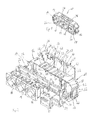
- the presentation of the Fig. 2 shows the device cup 10 of Fig. 1 in an exploded view.
- Fig. 2 It can be seen that the protective contact sockets 18, which form electrical installation devices, are inserted by means of latching hooks into an opening of the cover plate 22. Also, the data socket 20 is provided with latching hooks and inserted by means of these latching hooks in a through hole of the cover plate 24 and latched thereto.
- the interior of the frame 12 is divided by means of a partition wall 28 into two areas, namely on the one hand, the area in which power lines are supplied to the protective contact sockets 18 and on the other hand the area in which data lines of the data box 20 are supplied.
- the cover plates 22, 24 are each provided with resilient latching hooks 30, which are provided with inwardly to the interior of the frame 12 facing out latching hooks. These locking hooks 30 engage when placing the cover plates 22, 24 in groove-like recesses 32 in the circumferential wall of the frame 12 a.
- a width of the latching hook 30 is dimensioned so that it is only slightly smaller than a width of the groove-like recesses 32.
- the side edges of the latching hooks 30 are thereby at least partially against the side walls of the groove-like recesses 32 and thereby stabilize the frame 12 in the latched state considerably.
- the bottom plates 26, 28 are provided with resilient latching hooks 34 which are formed equal to the latching hooks 30 on the cover plates 22, 24. These locking hooks 34 engage in the groove-like recesses 32 and thereby stabilize the frame 12 in the locked state.
- the latching hooks 34 are arranged at the same distance from one another as the latching hooks 30 of the cover plates 22, 24. The bottom plates 26, 28 can thus also be attached to the frame in Fig. 2 front side of the frame 12 are snapped.
- the groove-like recesses 32 each with the outside, so from the interior of the frame 12 pioneering locking lugs 40, 42 are provided.
- the locking lugs 40 are engaged behind by the resilient latching hooks 30 after placing the cover plates 22, 24.
- the locking lugs 42 are engaged behind the touchdown of the bottom plates 26, 28 of the resilient latching hooks 34. Both the cover plates 22, 24 and the bottom plates 26, 28 are thereby securely locked to the frame 12.
- the bottom plates 26, 28 are also placed on the first edge 36 of the frame 12 become.
- the latching hooks 34 of the bottom plates 26, 28 would then engage behind the latching noses 40 in the region of the first edge 36 of the groove-like recesses 32.
- the cover plates 22, 24 could be placed on the second edge 38 of the frame 12.
- the bottom plate 26 has a perforation 54 which is formed by means of three, a first portion 56 and a second portion 58 of the bottom plate 26 connecting webs and intermediate through holes.
- the two sections 56, 58 are connected to each other only by three webs 60, wherein two of the webs are in the region of the side edges of the bottom plate 26, the third web is centered in the bottom plate 26.
- Between two webs 60 are slot-like through holes 62nd
- the portion 56 can now be easily separated from the portion 58 by the bottom plate 26 is bent. As a result, the webs 60 break through.
- either only the section 58, which then the bottom plate 28 in Fig. 2 forms, or only the portion 56 are placed on the frame 12.
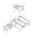
- the presentation of the Fig. 3 shows a device cup 50 according to the invention according to another embodiment of the invention.
- the device cup 50 has a frame 12 which is identical to the frame 12 of the device cup 10 of Fig. 1 and 2 is formed and therefore will not be explained again.
- the frame 12 of the device cup 50 is provided with a cover plate 22 and a total of three bottom plates 26.
- the cover plate 22 serves to accommodate two data-technical installation devices 52.
- two socket outlets 18 are inserted into the cover plate 22.
- the complete underside of the frame 12 is closed by means of two identical cover plates 26. Also the in 3 and 4 right part of the top of the frame 12 is closed by a cover plate 26. An accessibility of the live connections of the Schuko sockets 18 or a back of the data installation equipment 32 is thereby reliably prevented. It should be noted, however, that for the cover of the top of the frame 12, the same bottom plates 26 can be used, which are also provided for closing the underside of the frame 12. As a result of the invention, a device cup which can be used extremely flexibly is thereby created, which, however, manages by means of only a few different individual parts. Specifically, only one type of bottom plate, namely the bottom plate 26, is needed, which is then divided, if necessary, at the predetermined breaking point 54, see Fig. 2 ,
Landscapes
- Engineering & Computer Science (AREA)
- Architecture (AREA)
- Civil Engineering (AREA)
- Structural Engineering (AREA)
- Casings For Electric Apparatus (AREA)
- Connector Housings Or Holding Contact Members (AREA)
- Details Of Indoor Wiring (AREA)
Priority Applications (1)
| Application Number | Priority Date | Filing Date | Title |
|---|---|---|---|
| PL15166735T PL2953221T3 (pl) | 2014-06-06 | 2015-05-07 | Puszka instalacyjna do elektrycznych urządzeń instalacyjnych |
Applications Claiming Priority (1)
| Application Number | Priority Date | Filing Date | Title |
|---|---|---|---|
| DE102014210948.5A DE102014210948B4 (de) | 2014-06-06 | 2014-06-06 | Gerätebecher für elektrische Installationsgeräte |
Publications (2)
| Publication Number | Publication Date |
|---|---|
| EP2953221A1 true EP2953221A1 (fr) | 2015-12-09 |
| EP2953221B1 EP2953221B1 (fr) | 2020-08-19 |
Family
ID=53054934
Family Applications (1)
| Application Number | Title | Priority Date | Filing Date |
|---|---|---|---|
| EP15166735.9A Active EP2953221B1 (fr) | 2014-06-06 | 2015-05-07 | Panier de support d'appareillages pour appareils d'installation électriques |
Country Status (6)
| Country | Link |
|---|---|
| EP (1) | EP2953221B1 (fr) |
| DE (1) | DE102014210948B4 (fr) |
| ES (1) | ES2828449T3 (fr) |
| HU (1) | HUE051304T2 (fr) |
| PL (1) | PL2953221T3 (fr) |
| PT (1) | PT2953221T (fr) |
Citations (4)
| Publication number | Priority date | Publication date | Assignee | Title |
|---|---|---|---|---|
| EP0991158A1 (fr) * | 1998-10-01 | 2000-04-05 | Albert Ackermann GmbH & Co. KG | Une réception d'appareil pour boîtier pour appareillage installé sous plancher |
| DE202006010817U1 (de) * | 2006-04-26 | 2007-08-30 | Vergokan N.V. | Zugentlastung für Gerätebecher |
| DE102008015770A1 (de) * | 2008-03-26 | 2009-10-22 | Electraplan Solutions Gmbh | Versorgungseinheit für Unterfluranwendung |
| DE202011102159U1 (de) | 2011-06-22 | 2012-09-24 | Tehalit Gmbh | Gerätebecher für Unterflur-Elektroinstallationen |
-
2014
- 2014-06-06 DE DE102014210948.5A patent/DE102014210948B4/de active Active
-
2015
- 2015-05-07 PT PT151667359T patent/PT2953221T/pt unknown
- 2015-05-07 PL PL15166735T patent/PL2953221T3/pl unknown
- 2015-05-07 EP EP15166735.9A patent/EP2953221B1/fr active Active
- 2015-05-07 ES ES15166735T patent/ES2828449T3/es active Active
- 2015-05-07 HU HUE15166735A patent/HUE051304T2/hu unknown
Patent Citations (5)
| Publication number | Priority date | Publication date | Assignee | Title |
|---|---|---|---|---|
| EP0991158A1 (fr) * | 1998-10-01 | 2000-04-05 | Albert Ackermann GmbH & Co. KG | Une réception d'appareil pour boîtier pour appareillage installé sous plancher |
| DE19845335B4 (de) | 1998-10-01 | 2008-05-21 | Obo Bettermann Gmbh & Co. Kg | Geräteaufnahme für eine Unterflurgerätedose |
| DE202006010817U1 (de) * | 2006-04-26 | 2007-08-30 | Vergokan N.V. | Zugentlastung für Gerätebecher |
| DE102008015770A1 (de) * | 2008-03-26 | 2009-10-22 | Electraplan Solutions Gmbh | Versorgungseinheit für Unterfluranwendung |
| DE202011102159U1 (de) | 2011-06-22 | 2012-09-24 | Tehalit Gmbh | Gerätebecher für Unterflur-Elektroinstallationen |
Also Published As
| Publication number | Publication date |
|---|---|
| PL2953221T3 (pl) | 2021-02-08 |
| ES2828449T3 (es) | 2021-05-26 |
| HUE051304T2 (hu) | 2021-03-01 |
| DE102014210948B4 (de) | 2022-07-28 |
| DE102014210948A1 (de) | 2015-12-17 |
| EP2953221B1 (fr) | 2020-08-19 |
| PT2953221T (pt) | 2020-10-19 |
Similar Documents
| Publication | Publication Date | Title |
|---|---|---|
| DE102011002135B4 (de) | Steckerelement mit zweiter Kontaktsicherung | |
| EP2012390B1 (fr) | Pince de mise à la terre destinée à l'équilibrage du potentiel de canaux de câblage | |
| EP3016215A1 (fr) | Dispositif de mise a la terre de rails | |
| EP2858186B1 (fr) | Adaptateur de barre omnibus | |
| DE102008060808B4 (de) | Bodeneinbaukassette für elektrische Installationsgeräte | |
| EP2806516A1 (fr) | Bloc d'étanchéité pour des conducteurs individuels | |
| EP2953221B1 (fr) | Panier de support d'appareillages pour appareils d'installation électriques | |
| DE102024100111A1 (de) | Zähler- und Verteilerschrank | |
| EP2538510B1 (fr) | Panier d'appareillage pour installations électriques souterraines | |
| EP3136524B1 (fr) | Chaine d'ecrous de mise a la terre | |
| DE102006015317A1 (de) | Geräteeinbausatz zur Anordnung eines Gerätes in einer elektrischen Schaltanlage | |
| EP2019458A2 (fr) | Prise, en particulier prise de remorque | |
| EP1480309B1 (fr) | Bouchon de fermeture d'une ouverture prévue pour le passage de câbles | |
| EP2418746A2 (fr) | Boîtier d'appareillage pour appareils dýinstallation | |
| EP2639912B1 (fr) | Boîtier encastrable pour canaux d'intégration d'appareil et canal d'intégration d'appareils doté de celui-ci | |
| WO2013143930A1 (fr) | Module de système destiné au génie électrique d'immeubles et au génie des systèmes portiers de communication | |
| DE102009009500A1 (de) | Gehäuse | |
| DE202006010818U1 (de) | Gerätebecher | |
| DE102017112519B4 (de) | Haushaltsgerät | |
| EP3558058B1 (fr) | Meuble doté d'une traversée de câble et procédé de formation d'une traversée de câble | |
| DE9106787U1 (de) | Elektrodose | |
| DE102016225550A1 (de) | Gehäuseanordnung mit Leiterplattenhalter | |
| EP2876757B1 (fr) | Adaptateur de montage sous forme de cadre, assortiment d'adaptateurs de montage sous forme de cadre et dispositif doté d'un boîtier d'appareil et d'au moins un adaptateur de montage sous forme de cadre | |
| DE1490324C (de) | Im wesentlichen quaderförmiges Gehäuse für einzelne Geräte der Elektrotechnik | |
| DE1189185B (de) | Elektrische Sicherungsdose |
Legal Events
| Date | Code | Title | Description |
|---|---|---|---|
| PUAI | Public reference made under article 153(3) epc to a published international application that has entered the european phase |
Free format text: ORIGINAL CODE: 0009012 |
|
| AK | Designated contracting states |
Kind code of ref document: A1 Designated state(s): AL AT BE BG CH CY CZ DE DK EE ES FI FR GB GR HR HU IE IS IT LI LT LU LV MC MK MT NL NO PL PT RO RS SE SI SK SM TR |
|
| AX | Request for extension of the european patent |
Extension state: BA ME |
|
| 17P | Request for examination filed |
Effective date: 20160607 |
|
| RBV | Designated contracting states (corrected) |
Designated state(s): AL AT BE BG CH CY CZ DE DK EE ES FI FR GB GR HR HU IE IS IT LI LT LU LV MC MK MT NL NO PL PT RO RS SE SI SK SM TR |
|
| STAA | Information on the status of an ep patent application or granted ep patent |
Free format text: STATUS: EXAMINATION IS IN PROGRESS |
|
| 17Q | First examination report despatched |
Effective date: 20180227 |
|
| RIC1 | Information provided on ipc code assigned before grant |
Ipc: H02G 3/08 20060101ALI20200409BHEP Ipc: H02G 3/14 20060101ALN20200409BHEP Ipc: H02G 3/18 20060101AFI20200409BHEP |
|
| GRAP | Despatch of communication of intention to grant a patent |
Free format text: ORIGINAL CODE: EPIDOSNIGR1 |
|
| STAA | Information on the status of an ep patent application or granted ep patent |
Free format text: STATUS: GRANT OF PATENT IS INTENDED |
|
| INTG | Intention to grant announced |
Effective date: 20200519 |
|
| GRAS | Grant fee paid |
Free format text: ORIGINAL CODE: EPIDOSNIGR3 |
|
| GRAA | (expected) grant |
Free format text: ORIGINAL CODE: 0009210 |
|
| STAA | Information on the status of an ep patent application or granted ep patent |
Free format text: STATUS: THE PATENT HAS BEEN GRANTED |
|
| AK | Designated contracting states |
Kind code of ref document: B1 Designated state(s): AL AT BE BG CH CY CZ DE DK EE ES FI FR GB GR HR HU IE IS IT LI LT LU LV MC MK MT NL NO PL PT RO RS SE SI SK SM TR |
|
| REG | Reference to a national code |
Ref country code: CH Ref legal event code: EP |
|
| REG | Reference to a national code |
Ref country code: DE Ref legal event code: R096 Ref document number: 502015013256 Country of ref document: DE |
|
| REG | Reference to a national code |
Ref country code: AT Ref legal event code: REF Ref document number: 1305045 Country of ref document: AT Kind code of ref document: T Effective date: 20200915 |
|
| REG | Reference to a national code |
Ref country code: IE Ref legal event code: FG4D Free format text: LANGUAGE OF EP DOCUMENT: GERMAN |
|
| REG | Reference to a national code |
Ref country code: PT Ref legal event code: SC4A Ref document number: 2953221 Country of ref document: PT Date of ref document: 20201019 Kind code of ref document: T Free format text: AVAILABILITY OF NATIONAL TRANSLATION Effective date: 20201012 |
|
| REG | Reference to a national code |
Ref country code: FI Ref legal event code: FGE |
|
| REG | Reference to a national code |
Ref country code: NL Ref legal event code: FP |
|
| REG | Reference to a national code |
Ref country code: LT Ref legal event code: MG4D |
|
| PG25 | Lapsed in a contracting state [announced via postgrant information from national office to epo] |
Ref country code: SE Free format text: LAPSE BECAUSE OF FAILURE TO SUBMIT A TRANSLATION OF THE DESCRIPTION OR TO PAY THE FEE WITHIN THE PRESCRIBED TIME-LIMIT Effective date: 20200819 Ref country code: NO Free format text: LAPSE BECAUSE OF FAILURE TO SUBMIT A TRANSLATION OF THE DESCRIPTION OR TO PAY THE FEE WITHIN THE PRESCRIBED TIME-LIMIT Effective date: 20201119 Ref country code: HR Free format text: LAPSE BECAUSE OF FAILURE TO SUBMIT A TRANSLATION OF THE DESCRIPTION OR TO PAY THE FEE WITHIN THE PRESCRIBED TIME-LIMIT Effective date: 20200819 Ref country code: BG Free format text: LAPSE BECAUSE OF FAILURE TO SUBMIT A TRANSLATION OF THE DESCRIPTION OR TO PAY THE FEE WITHIN THE PRESCRIBED TIME-LIMIT Effective date: 20201119 Ref country code: GR Free format text: LAPSE BECAUSE OF FAILURE TO SUBMIT A TRANSLATION OF THE DESCRIPTION OR TO PAY THE FEE WITHIN THE PRESCRIBED TIME-LIMIT Effective date: 20201120 Ref country code: LT Free format text: LAPSE BECAUSE OF FAILURE TO SUBMIT A TRANSLATION OF THE DESCRIPTION OR TO PAY THE FEE WITHIN THE PRESCRIBED TIME-LIMIT Effective date: 20200819 |
|
| PG25 | Lapsed in a contracting state [announced via postgrant information from national office to epo] |
Ref country code: LV Free format text: LAPSE BECAUSE OF FAILURE TO SUBMIT A TRANSLATION OF THE DESCRIPTION OR TO PAY THE FEE WITHIN THE PRESCRIBED TIME-LIMIT Effective date: 20200819 Ref country code: RS Free format text: LAPSE BECAUSE OF FAILURE TO SUBMIT A TRANSLATION OF THE DESCRIPTION OR TO PAY THE FEE WITHIN THE PRESCRIBED TIME-LIMIT Effective date: 20200819 Ref country code: IS Free format text: LAPSE BECAUSE OF FAILURE TO SUBMIT A TRANSLATION OF THE DESCRIPTION OR TO PAY THE FEE WITHIN THE PRESCRIBED TIME-LIMIT Effective date: 20201219 |
|
| REG | Reference to a national code |
Ref country code: HU Ref legal event code: AG4A Ref document number: E051304 Country of ref document: HU |
|
| PG25 | Lapsed in a contracting state [announced via postgrant information from national office to epo] |
Ref country code: EE Free format text: LAPSE BECAUSE OF FAILURE TO SUBMIT A TRANSLATION OF THE DESCRIPTION OR TO PAY THE FEE WITHIN THE PRESCRIBED TIME-LIMIT Effective date: 20200819 Ref country code: SM Free format text: LAPSE BECAUSE OF FAILURE TO SUBMIT A TRANSLATION OF THE DESCRIPTION OR TO PAY THE FEE WITHIN THE PRESCRIBED TIME-LIMIT Effective date: 20200819 Ref country code: RO Free format text: LAPSE BECAUSE OF FAILURE TO SUBMIT A TRANSLATION OF THE DESCRIPTION OR TO PAY THE FEE WITHIN THE PRESCRIBED TIME-LIMIT Effective date: 20200819 Ref country code: DK Free format text: LAPSE BECAUSE OF FAILURE TO SUBMIT A TRANSLATION OF THE DESCRIPTION OR TO PAY THE FEE WITHIN THE PRESCRIBED TIME-LIMIT Effective date: 20200819 Ref country code: CZ Free format text: LAPSE BECAUSE OF FAILURE TO SUBMIT A TRANSLATION OF THE DESCRIPTION OR TO PAY THE FEE WITHIN THE PRESCRIBED TIME-LIMIT Effective date: 20200819 |
|
| REG | Reference to a national code |
Ref country code: DE Ref legal event code: R097 Ref document number: 502015013256 Country of ref document: DE |
|
| REG | Reference to a national code |
Ref country code: ES Ref legal event code: FG2A Ref document number: 2828449 Country of ref document: ES Kind code of ref document: T3 Effective date: 20210526 |
|
| PG25 | Lapsed in a contracting state [announced via postgrant information from national office to epo] |
Ref country code: AL Free format text: LAPSE BECAUSE OF FAILURE TO SUBMIT A TRANSLATION OF THE DESCRIPTION OR TO PAY THE FEE WITHIN THE PRESCRIBED TIME-LIMIT Effective date: 20200819 |
|
| PLBE | No opposition filed within time limit |
Free format text: ORIGINAL CODE: 0009261 |
|
| STAA | Information on the status of an ep patent application or granted ep patent |
Free format text: STATUS: NO OPPOSITION FILED WITHIN TIME LIMIT |
|
| PG25 | Lapsed in a contracting state [announced via postgrant information from national office to epo] |
Ref country code: SK Free format text: LAPSE BECAUSE OF FAILURE TO SUBMIT A TRANSLATION OF THE DESCRIPTION OR TO PAY THE FEE WITHIN THE PRESCRIBED TIME-LIMIT Effective date: 20200819 |
|
| 26N | No opposition filed |
Effective date: 20210520 |
|
| PG25 | Lapsed in a contracting state [announced via postgrant information from national office to epo] |
Ref country code: IT Free format text: LAPSE BECAUSE OF FAILURE TO SUBMIT A TRANSLATION OF THE DESCRIPTION OR TO PAY THE FEE WITHIN THE PRESCRIBED TIME-LIMIT Effective date: 20200819 |
|
| PG25 | Lapsed in a contracting state [announced via postgrant information from national office to epo] |
Ref country code: SI Free format text: LAPSE BECAUSE OF FAILURE TO SUBMIT A TRANSLATION OF THE DESCRIPTION OR TO PAY THE FEE WITHIN THE PRESCRIBED TIME-LIMIT Effective date: 20200819 |
|
| REG | Reference to a national code |
Ref country code: CH Ref legal event code: PL |
|
| GBPC | Gb: european patent ceased through non-payment of renewal fee |
Effective date: 20210507 |
|
| PG25 | Lapsed in a contracting state [announced via postgrant information from national office to epo] |
Ref country code: LI Free format text: LAPSE BECAUSE OF NON-PAYMENT OF DUE FEES Effective date: 20210531 Ref country code: MC Free format text: LAPSE BECAUSE OF FAILURE TO SUBMIT A TRANSLATION OF THE DESCRIPTION OR TO PAY THE FEE WITHIN THE PRESCRIBED TIME-LIMIT Effective date: 20200819 Ref country code: LU Free format text: LAPSE BECAUSE OF NON-PAYMENT OF DUE FEES Effective date: 20210507 Ref country code: CH Free format text: LAPSE BECAUSE OF NON-PAYMENT OF DUE FEES Effective date: 20210531 |
|
| PG25 | Lapsed in a contracting state [announced via postgrant information from national office to epo] |
Ref country code: IE Free format text: LAPSE BECAUSE OF NON-PAYMENT OF DUE FEES Effective date: 20210507 Ref country code: GB Free format text: LAPSE BECAUSE OF NON-PAYMENT OF DUE FEES Effective date: 20210507 |
|
| PG25 | Lapsed in a contracting state [announced via postgrant information from national office to epo] |
Ref country code: CY Free format text: LAPSE BECAUSE OF FAILURE TO SUBMIT A TRANSLATION OF THE DESCRIPTION OR TO PAY THE FEE WITHIN THE PRESCRIBED TIME-LIMIT Effective date: 20200819 |
|
| P01 | Opt-out of the competence of the unified patent court (upc) registered |
Effective date: 20230525 |
|
| PG25 | Lapsed in a contracting state [announced via postgrant information from national office to epo] |
Ref country code: MK Free format text: LAPSE BECAUSE OF FAILURE TO SUBMIT A TRANSLATION OF THE DESCRIPTION OR TO PAY THE FEE WITHIN THE PRESCRIBED TIME-LIMIT Effective date: 20200819 |
|
| PG25 | Lapsed in a contracting state [announced via postgrant information from national office to epo] |
Ref country code: TR Free format text: LAPSE BECAUSE OF FAILURE TO SUBMIT A TRANSLATION OF THE DESCRIPTION OR TO PAY THE FEE WITHIN THE PRESCRIBED TIME-LIMIT Effective date: 20200819 |
|
| PGFP | Annual fee paid to national office [announced via postgrant information from national office to epo] |
Ref country code: ES Payment date: 20240614 Year of fee payment: 10 |
|
| PGFP | Annual fee paid to national office [announced via postgrant information from national office to epo] |
Ref country code: FI Payment date: 20240521 Year of fee payment: 10 |
|
| PGFP | Annual fee paid to national office [announced via postgrant information from national office to epo] |
Ref country code: PL Payment date: 20240415 Year of fee payment: 10 |
|
| PG25 | Lapsed in a contracting state [announced via postgrant information from national office to epo] |
Ref country code: MT Free format text: LAPSE BECAUSE OF FAILURE TO SUBMIT A TRANSLATION OF THE DESCRIPTION OR TO PAY THE FEE WITHIN THE PRESCRIBED TIME-LIMIT Effective date: 20200819 |
|
| PGFP | Annual fee paid to national office [announced via postgrant information from national office to epo] |
Ref country code: NL Payment date: 20250522 Year of fee payment: 11 |
|
| PGFP | Annual fee paid to national office [announced via postgrant information from national office to epo] |
Ref country code: DE Payment date: 20250521 Year of fee payment: 11 |
|
| PGFP | Annual fee paid to national office [announced via postgrant information from national office to epo] |
Ref country code: BE Payment date: 20250520 Year of fee payment: 11 |
|
| PGFP | Annual fee paid to national office [announced via postgrant information from national office to epo] |
Ref country code: PT Payment date: 20250507 Year of fee payment: 11 |
|
| PGFP | Annual fee paid to national office [announced via postgrant information from national office to epo] |
Ref country code: FR Payment date: 20250521 Year of fee payment: 11 Ref country code: HU Payment date: 20250505 Year of fee payment: 11 |
|
| PGFP | Annual fee paid to national office [announced via postgrant information from national office to epo] |
Ref country code: AT Payment date: 20250519 Year of fee payment: 11 |
|
| PG25 | Lapsed in a contracting state [announced via postgrant information from national office to epo] |
Ref country code: FI Free format text: LAPSE BECAUSE OF NON-PAYMENT OF DUE FEES Effective date: 20250507 |