EP2953264A2 - Pulsbreitenmodulator für luftfahrtanwendung - Google Patents
Pulsbreitenmodulator für luftfahrtanwendung Download PDFInfo
- Publication number
- EP2953264A2 EP2953264A2 EP15170812.0A EP15170812A EP2953264A2 EP 2953264 A2 EP2953264 A2 EP 2953264A2 EP 15170812 A EP15170812 A EP 15170812A EP 2953264 A2 EP2953264 A2 EP 2953264A2
- Authority
- EP
- European Patent Office
- Prior art keywords
- pulse width
- width modulator
- duty cycle
- pulse
- light
- Prior art date
- Legal status (The legal status is an assumption and is not a legal conclusion. Google has not performed a legal analysis and makes no representation as to the accuracy of the status listed.)
- Withdrawn
Links
- 230000000630 rising effect Effects 0.000 claims abstract description 18
- 238000000034 method Methods 0.000 claims description 11
- 230000008859 change Effects 0.000 claims description 5
- 230000004044 response Effects 0.000 claims description 3
- 230000008569 process Effects 0.000 description 7
- 230000007704 transition Effects 0.000 description 7
- 238000009499 grossing Methods 0.000 description 5
- 239000007787 solid Substances 0.000 description 5
- 230000001052 transient effect Effects 0.000 description 5
- 230000008901 benefit Effects 0.000 description 3
- 230000007423 decrease Effects 0.000 description 3
- 230000000694 effects Effects 0.000 description 3
- 239000003990 capacitor Substances 0.000 description 2
- 230000003247 decreasing effect Effects 0.000 description 2
- 238000001514 detection method Methods 0.000 description 2
- 238000010586 diagram Methods 0.000 description 2
- 239000004065 semiconductor Substances 0.000 description 2
- 230000005669 field effect Effects 0.000 description 1
- 230000010006 flight Effects 0.000 description 1
- 230000006870 function Effects 0.000 description 1
- 229910044991 metal oxide Inorganic materials 0.000 description 1
- 150000004706 metal oxides Chemical class 0.000 description 1
- 230000004048 modification Effects 0.000 description 1
- 238000012986 modification Methods 0.000 description 1
- 230000003287 optical effect Effects 0.000 description 1
- 238000004904 shortening Methods 0.000 description 1
Images






Classifications
-
- H—ELECTRICITY
- H02—GENERATION; CONVERSION OR DISTRIBUTION OF ELECTRIC POWER
- H02M—APPARATUS FOR CONVERSION BETWEEN AC AND AC, BETWEEN AC AND DC, OR BETWEEN DC AND DC, AND FOR USE WITH MAINS OR SIMILAR POWER SUPPLY SYSTEMS; CONVERSION OF DC OR AC INPUT POWER INTO SURGE OUTPUT POWER; CONTROL OR REGULATION THEREOF
- H02M7/00—Conversion of AC power input into DC power output; Conversion of DC power input into AC power output
- H02M7/42—Conversion of DC power input into AC power output without possibility of reversal
- H02M7/44—Conversion of DC power input into AC power output without possibility of reversal by static converters
- H02M7/48—Conversion of DC power input into AC power output without possibility of reversal by static converters using discharge tubes with control electrode or semiconductor devices with control electrode
- H02M7/53—Conversion of DC power input into AC power output without possibility of reversal by static converters using discharge tubes with control electrode or semiconductor devices with control electrode using devices of a triode or transistor type requiring continuous application of a control signal
- H02M7/537—Conversion of DC power input into AC power output without possibility of reversal by static converters using discharge tubes with control electrode or semiconductor devices with control electrode using devices of a triode or transistor type requiring continuous application of a control signal using semiconductor devices only, e.g. single switched pulse inverters
- H02M7/539—Conversion of DC power input into AC power output without possibility of reversal by static converters using discharge tubes with control electrode or semiconductor devices with control electrode using devices of a triode or transistor type requiring continuous application of a control signal using semiconductor devices only, e.g. single switched pulse inverters with automatic control of output wave form or frequency
- H02M7/5395—Conversion of DC power input into AC power output without possibility of reversal by static converters using discharge tubes with control electrode or semiconductor devices with control electrode using devices of a triode or transistor type requiring continuous application of a control signal using semiconductor devices only, e.g. single switched pulse inverters with automatic control of output wave form or frequency by pulse-width modulation
-
- H—ELECTRICITY
- H03—ELECTRONIC CIRCUITRY
- H03K—PULSE TECHNIQUE
- H03K3/00—Circuits for generating electric pulses; Monostable, bistable or multistable circuits
- H03K3/01—Details
- H03K3/017—Adjustment of width or dutycycle of pulses
-
- H—ELECTRICITY
- H02—GENERATION; CONVERSION OR DISTRIBUTION OF ELECTRIC POWER
- H02M—APPARATUS FOR CONVERSION BETWEEN AC AND AC, BETWEEN AC AND DC, OR BETWEEN DC AND DC, AND FOR USE WITH MAINS OR SIMILAR POWER SUPPLY SYSTEMS; CONVERSION OF DC OR AC INPUT POWER INTO SURGE OUTPUT POWER; CONTROL OR REGULATION THEREOF
- H02M1/00—Details of apparatus for conversion
- H02M1/44—Circuits or arrangements for compensating for electromagnetic interference in converters or inverters
-
- H—ELECTRICITY
- H03—ELECTRONIC CIRCUITRY
- H03K—PULSE TECHNIQUE
- H03K4/00—Generating pulses having essentially a finite slope or stepped portions
- H03K4/94—Generating pulses having essentially a finite slope or stepped portions having trapezoidal shape
-
- H—ELECTRICITY
- H03—ELECTRONIC CIRCUITRY
- H03K—PULSE TECHNIQUE
- H03K7/00—Modulating pulses with a continuously-variable modulating signal
- H03K7/08—Duration or width modulation ; Duty cycle modulation
-
- H—ELECTRICITY
- H05—ELECTRIC TECHNIQUES NOT OTHERWISE PROVIDED FOR
- H05B—ELECTRIC HEATING; ELECTRIC LIGHT SOURCES NOT OTHERWISE PROVIDED FOR; CIRCUIT ARRANGEMENTS FOR ELECTRIC LIGHT SOURCES, IN GENERAL
- H05B45/00—Circuit arrangements for operating light-emitting diodes [LED]
-
- H—ELECTRICITY
- H05—ELECTRIC TECHNIQUES NOT OTHERWISE PROVIDED FOR
- H05B—ELECTRIC HEATING; ELECTRIC LIGHT SOURCES NOT OTHERWISE PROVIDED FOR; CIRCUIT ARRANGEMENTS FOR ELECTRIC LIGHT SOURCES, IN GENERAL
- H05B45/00—Circuit arrangements for operating light-emitting diodes [LED]
- H05B45/10—Controlling the intensity of the light
-
- H—ELECTRICITY
- H05—ELECTRIC TECHNIQUES NOT OTHERWISE PROVIDED FOR
- H05B—ELECTRIC HEATING; ELECTRIC LIGHT SOURCES NOT OTHERWISE PROVIDED FOR; CIRCUIT ARRANGEMENTS FOR ELECTRIC LIGHT SOURCES, IN GENERAL
- H05B45/00—Circuit arrangements for operating light-emitting diodes [LED]
- H05B45/10—Controlling the intensity of the light
- H05B45/12—Controlling the intensity of the light using optical feedback
-
- H—ELECTRICITY
- H05—ELECTRIC TECHNIQUES NOT OTHERWISE PROVIDED FOR
- H05B—ELECTRIC HEATING; ELECTRIC LIGHT SOURCES NOT OTHERWISE PROVIDED FOR; CIRCUIT ARRANGEMENTS FOR ELECTRIC LIGHT SOURCES, IN GENERAL
- H05B45/00—Circuit arrangements for operating light-emitting diodes [LED]
- H05B45/30—Driver circuits
- H05B45/32—Pulse-control circuits
- H05B45/325—Pulse-width modulation [PWM]
-
- H—ELECTRICITY
- H05—ELECTRIC TECHNIQUES NOT OTHERWISE PROVIDED FOR
- H05B—ELECTRIC HEATING; ELECTRIC LIGHT SOURCES NOT OTHERWISE PROVIDED FOR; CIRCUIT ARRANGEMENTS FOR ELECTRIC LIGHT SOURCES, IN GENERAL
- H05B45/00—Circuit arrangements for operating light-emitting diodes [LED]
- H05B45/30—Driver circuits
- H05B45/37—Converter circuits
-
- H—ELECTRICITY
- H05—ELECTRIC TECHNIQUES NOT OTHERWISE PROVIDED FOR
- H05B—ELECTRIC HEATING; ELECTRIC LIGHT SOURCES NOT OTHERWISE PROVIDED FOR; CIRCUIT ARRANGEMENTS FOR ELECTRIC LIGHT SOURCES, IN GENERAL
- H05B47/00—Circuit arrangements for operating light sources in general, i.e. where the type of light source is not relevant
- H05B47/10—Controlling the light source
- H05B47/105—Controlling the light source in response to determined parameters
- H05B47/11—Controlling the light source in response to determined parameters by determining the brightness or colour temperature of ambient light
-
- B—PERFORMING OPERATIONS; TRANSPORTING
- B64—AIRCRAFT; AVIATION; COSMONAUTICS
- B64D—EQUIPMENT FOR FITTING IN OR TO AIRCRAFT; FLIGHT SUITS; PARACHUTES; ARRANGEMENT OR MOUNTING OF POWER PLANTS OR PROPULSION TRANSMISSIONS IN AIRCRAFT
- B64D11/00—Passenger or crew accommodation; Flight-deck installations not otherwise provided for
- B64D11/003—Stowage devices for passengers' personal luggage
-
- B—PERFORMING OPERATIONS; TRANSPORTING
- B64—AIRCRAFT; AVIATION; COSMONAUTICS
- B64D—EQUIPMENT FOR FITTING IN OR TO AIRCRAFT; FLIGHT SUITS; PARACHUTES; ARRANGEMENT OR MOUNTING OF POWER PLANTS OR PROPULSION TRANSMISSIONS IN AIRCRAFT
- B64D11/00—Passenger or crew accommodation; Flight-deck installations not otherwise provided for
- B64D2011/0038—Illumination systems for cabins as a whole
-
- B—PERFORMING OPERATIONS; TRANSPORTING
- B64—AIRCRAFT; AVIATION; COSMONAUTICS
- B64D—EQUIPMENT FOR FITTING IN OR TO AIRCRAFT; FLIGHT SUITS; PARACHUTES; ARRANGEMENT OR MOUNTING OF POWER PLANTS OR PROPULSION TRANSMISSIONS IN AIRCRAFT
- B64D11/00—Passenger or crew accommodation; Flight-deck installations not otherwise provided for
- B64D2011/0053—Cabin passenger reading lights
-
- H—ELECTRICITY
- H05—ELECTRIC TECHNIQUES NOT OTHERWISE PROVIDED FOR
- H05B—ELECTRIC HEATING; ELECTRIC LIGHT SOURCES NOT OTHERWISE PROVIDED FOR; CIRCUIT ARRANGEMENTS FOR ELECTRIC LIGHT SOURCES, IN GENERAL
- H05B45/00—Circuit arrangements for operating light-emitting diodes [LED]
- H05B45/30—Driver circuits
- H05B45/36—Circuits for reducing or suppressing harmonics, ripples or electromagnetic interferences [EMI]
-
- Y—GENERAL TAGGING OF NEW TECHNOLOGICAL DEVELOPMENTS; GENERAL TAGGING OF CROSS-SECTIONAL TECHNOLOGIES SPANNING OVER SEVERAL SECTIONS OF THE IPC; TECHNICAL SUBJECTS COVERED BY FORMER USPC CROSS-REFERENCE ART COLLECTIONS [XRACs] AND DIGESTS
- Y02—TECHNOLOGIES OR APPLICATIONS FOR MITIGATION OR ADAPTATION AGAINST CLIMATE CHANGE
- Y02B—CLIMATE CHANGE MITIGATION TECHNOLOGIES RELATED TO BUILDINGS, e.g. HOUSING, HOUSE APPLIANCES OR RELATED END-USER APPLICATIONS
- Y02B20/00—Energy efficient lighting technologies, e.g. halogen lamps or gas discharge lamps
- Y02B20/40—Control techniques providing energy savings, e.g. smart controller or presence detection
Definitions
- the present invention relates in general, but not exclusively, to a pulse width modulator for use in aviation.
- LED Light Emitting Diode
- a pulse width modulator for use in avionics comprising an input operable to receive a direct current input and an output switch controlled to provide a pulse train having a duty cycle, whereby the output switch is configured such that each pulse within the pulse train has at least one of a sloping rising or falling edge.
- the duty cycle may be changed incrementally towards the second duty cycle.
- Each increment of change may occur at a predetermined period of time.
- the pulse width modulator may comprise a sensor input operable to receive data, from a sensor, and the duty cycle is determined in accordance with the received data.
- the pulse width modulator may comprise a memory configured to store a look up table, wherein the look up table has the received data associated with the corresponding duty cycle.
- the received data may be logarithmically associated with the corresponding duty cycle.
- the pulse width modulator may comprise a transceiver operable to connect to a second pulse width modulator, the transceiver operable to provide to the second pulse width modulator data indicative of the duty cycle.
- the pulse width modulator may comprise a transceiver operable to connect to a second pulse width modulator, the transceiver operable to receive from the second pulse width modulator data indicative of the duty cycle.
- the electrical device may be a light box comprising one or more lights.
- the system may comprise a light sensor connected to the pulse width modulator.
- a method of performing pulse width modulation for use in avionics comprising receiving a direct current input and controlling an output switch to provide a pulse train having a duty cycle, whereby each pulse within the pulse train has at least one of a sloping rising or falling edge.
- firmware comprising microprocessor readable instructions which, when loaded onto a microprocessor, configures the microprocessor to perform the method of the above.
- a pulse width modulator device 100 (hereinafter termed “a device”) is shown.
- the device 100 will be provided either with each seat in an aircraft cabin or will be provided for an area within the aircraft cabin.
- the device has several input lines and several output lines which are connected to other apparatuses external to the device 100.
- the device 100 comprises a power supply unit 120.
- the power supply unit 120 receives a direct current (DC) voltage from an external power supply (not shown).
- the external power supply is provided by a switched mode/filtered power supply located in the aircraft in which the device 100 is fitted. This external power supply is between 20.5V and 32.2V, and is typically 28V.
- the power supply unit 120 includes an inline fuse which will isolate the external power supply in the event of a short circuit or overload condition. Further, the power supply unit 120 provides protection against reverse polarity and power spike situations.
- the device 100 also comprises an analogue to digital converter (hereinafter termed "ADC") 130.
- ADC 130 is connected to a light sensor 135.
- the light sensor 135 is external to the device 100.
- the ADC receives an analogue voltage from the light sensor 135. This analogue voltage indicates the ambient light within the cabin of the aircraft as will be explained with reference to Figure 4 .
- the ADC 130 is a 13-bit ADC meaning that the analogue voltage output from the light sensor 135 is converted into a 13 bit digital number. The function of the ADC 130 will be described later.
- the device 100 also comprises a controller 110.
- the output of the ADC 130 is fed into the controller 110.
- Also fed into the controller 110 is an output from a sensor on stowage compartment 140.
- the optional sensor on the stowage compartment 140 senses whether the stowage compartment is opened or closed. This will be explained later.
- Further connected to the controller 110 are a transceiver 125 and a pulse width modulator switch 115.
- the transceiver 125 is used to communicate with other devices 100 in a master/slave configuration shown in Figure 3 and will be explained later.
- the pulse width modulator switch 115 is, in embodiments, a Metal Oxide Semiconductor Field Effect Transistor (MOSFET).
- MOSFET Metal Oxide Semiconductor Field Effect Transistor
- the controller 110 has memory 105.
- the memory 105 has stored therein computer readable instructions (sometimes called firmware). These instructions are formed of computer code.
- the memory 105 is read-only memory that cannot be re-written. This ensures integrity of the code which is important in the context of aviation.
- the memory 105 is solid-state memory, although the invention is not so limited.
- the memory 105 stores a look-up table.
- the look-up table provides, for any value of ambient light detected by the light sensor 135, a corresponding ratio of time on/time off for the pulse width modulator.
- the look-up table will be described later.
- the pulse width modulator switch 115 in addition to receiving instructions from the controller 110 also receives its power from the power supply unit 120.
- the output of the pulse width modulator switch 115 is a pulse width modulated signal which has a trapezoidal shape.
- the pulse width modulator switch 115 is a power MOSFET.
- the pulse width modulator switch 115 switches at a frequency of 420Hz.
- the pulse width modulator switch 115 is, in embodiments, connected to an external light assembly (not shown). By switching at this frequency, any flicker at low light intensities will not be perceptible to the user.
- the maximum output current provided by the device 100 is 3A.
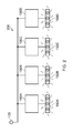
- a first system 200 is shown where the light sensor 135 is connected to a plurality of devices 100. This enables one light sensor 135 to provide ambient light levels to a plurality of devices 100. This is shown in Figure 2 where one light sensor 135 is connected to four devices 100A-100D. Each of the devices 100A-100D is connected to respective banks of lights 150A-150B. Each respective bank of lights 150A-150D are so-called feature lights made of Light Emitting Diode type bulbs and are located around a passenger seat in an aircraft cabin. These feature lights provide lighting around cabin furniture, and should vary with the ambient light within the aircraft cabin.
- the light sensor 135 to detect the ambient light in a region of the cabin, it is possible to set the light provided by the feature lights located within this region. It should be noted that in this configuration, although the devices 100A-100D receive the same output from the light sensor 135, the devices 100A-100D otherwise operate independently of one another.
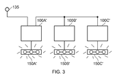
- a second system 300 is shown where the light sensor 135 is connected to a single device 100A' and that single device 100A' is connected to a plurality of other devices 100B'-100C'.
- the single device 100A' is the so-called "master” device and the other devices 100B'-100C' are the so-called “slave” devices.
- the single device 100A' controls the operation of the other devices 100B'-100C'. This will be explained later.
- Each of the devices 100A'-100C' are connected to respective banks of feature lights 150A'-150C'.
- the light sensor 135 comprises a signal smoothing circuit 405.
- the signal smoothing circuit 405 has the positive and negative power supply input into the circuit 405. Similar to the device 100, the external power supply to the signal smoothing circuit 405 is provided by a switched power supply located within the aircraft.
- the signal smoothing circuit 405 provides power to the light sensor circuit 135 and removes any transient or reverse polarity issues that may arise. Further, the signal smoothing circuit 135 provides the analogue voltage to the device 100. This analogue voltage is indicative of the ambient light within the aircraft cabin.
- the light sensor 135 also comprises a light photo sensor 410.
- the light photo sensor 410 has a phototransistor that peaks in the human luminosity curve and so provides a response similar to the human eye.
- a typical example of the light photo sensor 410 is an APDS9002 made by Avago Technology ®.
- a resistor 415 is also connected to the light photo sensor 410. This, in embodiments, is 51k ⁇ and is used to generate the voltage output from the light photo sensor 410 (the APDS9002 package actually outputs a current waveform).
- a capacitor 420 is provided in parallel to the resistor 410 to remove transient voltages. The capacitor 420 has a value of 0.1 ⁇ F.
- a graph 500 is shown.
- This graph 500 shows the ambient light levels 510 as detected by the light sensor 135. These ambient light levels are shown as a percentage of a range and are provided to the device 100.
- the range of ambient light levels range from 0% (darkness) to 100% (very bright).
- the ambient light levels are capped at 200 Lux because it is considered in-perceivable to a human to distinguish between different values over 200 Lux in an aircraft cabin.
- the light sensor 135 detects that the ambient light is 25% of its maximum level.
- the light sensor 135 provides a voltage indicative of this value of ambient light.
- the ADC 130 within the device 100 converts this voltage to a binary number.
- the controller 110 interrogates the look-up table located within memory 105 and determines an appropriate ratio of time on/time off for that binary number. In other words, the look-up table provides appropriate ratios of time on/time off for different values of ambient light.
- the binary numbers increase linearly with the ambient light. In other words, there is a linear relationship between the binary numbers and the ambient light.
- the human eye is more sensitive to changes in light when the ambient level of light is low, it is preferred to have a logarithmic relationship between the binary numbers and the ambient light. In other words, at low ambient light levels, the resolution of changes in ambient light levels increases. Conversely, in medium to high light intensity levels, where the changes in light levels are not so easily differentiated, the resolution of changes in ambient light levels is lower.
- FIG. 10 A graphical representation of the Look-Up table is shown in Figure 10 .
- the percentage of maximum ambient light level between 0 and 200 Lux
- the percentage of maximum output light from the light bulb which is an LED in the specific embodiment. These percentage values are the same.
- the horizontal axis shows the percentage ratio of time on/time off which is the pulse width modulation level.
- the controller 110 switches the pulse width modulation switch 115 to have a 25% ratio of time on/time off.
- each pulse is trapezoidal in shape.
- the rise and fall time of the pulse is sloped rather than substantially vertical. The effect of this will become apparent later, but by sloping the rise and/or fall time of the pulse, the electromagnetic interference is reduced.
- the light sensor 135 detects that the ambient light is 75% of its maximum level.
- the controller 110 switches the pulse width modulation switch 115 to have a 98.8% ratio of time on/time off. This is because the user's eye is more sensitive to low light levels and so the look up table provides an exponential relationship between the ambient light level and the ratio of time on/time off as explained above.
- the transition from 25% of the maximum level to 75% of the maximum level is performed over a period of time. This is indicated by the slope between region A and region B in Figure 5 , but actually occurs between any changes in lighting levels that are noticeable to the passenger.
- the transition between two levels takes place over several seconds to ensure a smooth transition in the lighting levels.
- the transition between 25% of the maximum level and 75% of the maximum level takes place over 2.5 seconds. This avoids a sharp change in the lighting levels which may be uncomfortable for the passenger.
- This transition is achieved by increasing the value output to the pulse width modulation switch 115 by one bit every 125ms. In other words, the value of the duty cycle will increase very gradually between the two levels.
- the transition was from a higher level to a lower level, the value output to the pulse width modulator switch 115 would be reduced by one bit every 125ms. Further, the transition may be made quicker or longer by shortening or lengthening the period at which one bit is changed and/or by increasing or decreasing the change at each period.
- the light sensor 135 detects that the ambient light is 100% of its maximum level. Therefore, the controller 110 switches the pulse width modulation switch 115 to be on.
- the light sensor 135 detects that the ambient light is 50% of its maximum level. Again, after interrogating the look-up table, the controller 110 switches the pulse width modulation switch 115 to have a 94.1% ratio of time on/time off.
- the light sensor 135 detects that the ambient light is 25% of its maximum level. Again, after interrogating the look-up table, the controller 110 switches the pulse width modulation switch 115 to have a 74.6% ratio of time on/time off.
- the light sensor 135 detects that the ambient light is 0% of its maximum level (i.e.
- the controller 110 switches the pulse width modulation switch 115 to be off (or at least to a predetermined minimum value).
- the light sensor 135 detects that the ambient light is 25% of its maximum level. Again, after interrogating the look-up table, the controller 110 switches the pulse width modulation switch 115 to have a 74.6% ratio of time on/time off.
- a single pulse 600 from area 515 of Figure 5 is shown in more detail.
- the pulse actually has sloping edges and is thus a trapezoidal shape.
- the rising edge 605 has a rise time, t rise , of between 10 and 100 ⁇ s before reaching the peak steady voltage 610 of, in this case, 28V.
- the falling edge 615 has a fall time, t fall , of between 10 and 100 ⁇ s.
- the rising edge will be between 50 and 60 ⁇ s.
- This range is advantageous because whilst it is useful to have a gradual slope on the rising and falling edge of the pulse to reduce the electromagnetic interference, the introduction of a slope means that the overall time for the pulse is increased and thus the frequency of the pulse width modulation signal is reduced. This is particularly relevant where the duty cycle of the pulse width modulated signal is around 50%. This is because for any pulse width modulation frequency, the pulse would normally be on for 50% of the time of the time and would be off for 50% of the time. However, if the time for the rising and falling edge is too high, a 50% duty cycle will not be achieved. Therefore, the range of between 50 ⁇ s and 60 ⁇ s for either or both of the rising and falling edge is a particularly useful compromise.
- the controller 110 gradually switches on the pulse width modulator switch 115.
- the controller 110 gradually increases the gate voltage on the MOSFET so that the MOSFET operates in the triode mode for a period of time.
- the output transistor is driven from the cutoff mode (i.e. the transistor being "off") to the active mode (i.e. the transistor being "on") as quickly as possible.
- the time taken for the transistor to switch from the cutoff mode to the active mode is t rise and the time taken for the transistor to switch from the active mode to the cutoff mode is t fall .
- the controller 110 linearly increases or decreases the gate voltage to linearly switch on or switch off the MOSFET. The effect of this linear increase or decrease in gate voltage is a slope on the rise and/or falling edge of the pulse.
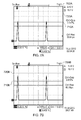
- FIG. 7A an oscilloscope display 700A is shown.
- This display 700A has a solid black line 710A which is the turn on voltage point of the bank of lights. Further, the DC limit of the bank of lights is shown by the dotted lines 720A.
- the bank of lights will be just switching on (as the voltage is just above black solid line 710A).
- the duty cycle of the pulse width modulation switch 115 is 3.347%. Further, the rise (and fall) time of the edge is 50.64 ⁇ s.
- an oscilloscope display 700B is shown.
- This display 700B has a solid black line 710B which is the turn on voltage point of the bank of lights. Further, the DC limit of the bank of lights is shown by the dotted lines 720B.
- the bank of lights will be in conduction and will be barely visible.
- Another advantage with the sloped rising and falling edges is that for low duty cycles (i.e. the pulse width modulation switch is mostly off), the very short periods for which the pulse width modulation switch 115 is on are not seen as transient spikes as can occur with very sharp rising and falling edges. This means that the device 100 in which the pulse width modulation switch 115 generates sloping rising and falling edges has much better control for low output power situations.
- an oscilloscope display 700C is shown.
- This display 700C has a solid black line 710C which is the turn on voltage point of the bank of lights. Further, the DC limit of the bank of lights is shown by the dotted lines 720C.
- the bank of lights will operate at about 10% of maximum brightness. This is because the bank of lights are receiving the full 28V DC for 10.35% of the time. This means that the duty cycle of the pulse width modulation switch 115 is 10.35%. Further, the rise (and fall) time of the edge is around 68 ⁇ s at 68.15 ⁇ s.
- an oscilloscope display 700D is shown.
- This display 700D has a solid black line 710D which is the turn on voltage point of the bank of lights. Further, the DC limit of the bank of lights is shown by the dotted lines 720D.
- the bank of lights will operate at about 50% of maximum brightness. This is because the bank of lights are receiving the full 28V DC for 49.68% of the time. This means that the duty cycle of the pulse width modulation switch 115 is 49.68%. Further, the rise (and fall) time of the edge is around 68 ⁇ s at 68.24 ⁇ s.
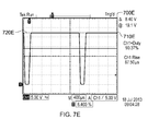
- an oscilloscope display 700E is shown.
- This display 700E has a solid black line 710E which is the turn on voltage point of the bank of lights. Further, the DC limit of the bank of lights is shown by the dotted lines 720E.
- the bank of lights will operate at about 90% of maximum brightness. This is because the bank of lights are receiving the full 28V DC for 90.37% of the time. This means that the duty cycle of the pulse width modulation switch 115 is 90.37%. Further, the rise (and fall) time of the edge is around 68 ⁇ s at 67.50 ⁇ s.
- the bank of lights is operating at 90% of full power, in reality, the human eye would not differentiate between 90% of full power and 100% of full power. This again indicates that a logarithmic relationship for the resolution of changes between light levels is useful.
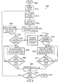
- FIG. 8 a flowchart 800 describing the operation of the device 100 and the first and second systems is described.
- the flowchart 800 starts at step 805. This start step occurs when power is first applied to the device 100.
- an initialisation step 810 is carried out. During the initialisation step, the timers within the firmware, such as the watchdog timer, are set up. Also, the ADC 130 is setup and checked. The initialisation step is standard in any device that receives external signal and is controlled by firmware.
- the ADC 130 is checked to confirm that it is ready to receive readings from the light sensor 135. This is step 815. After the ADC 130 is ready, the values from the light sensor 135 are read. In embodiments, 64 consecutive values of light sensor reading are captured. This is step 820. The average light sensor value is then determined in step 825. By obtaining the average light sensor value, the effect of any transient changes in ambient light is reduced.
- the average light sensor value is used to interrogate the look-up table.
- the appropriate value for the pulse modulation switch is selected from the look-up table. This is step 830.
- a check is then made to see if the stowage compartment which contains a light from the light box is closed. This is step 835. In particular, a check is made to see if an infra-red sensor located within the stowage compartment indicates that the stowage compartment is open or closed.
- the controller 110 switches the light box off. It may be possible for the controller 110 to instantly switch the light box off. However, this rapid change in lighting conditions can be unpleasant for the passenger. Therefore, and as explained above, the controller 135 gradually reduces the lighting level of the light box. Specifically, the controller 110 reduces the pulse width modulated switch value by 1 bit. This is step 840. The controller 110 checks whether the stowage compartment is still closed. If the stowage compartment is still closed, the "yes" path is followed and the controller 110 reduces the pulse width modulated switch value by 1 bit.
- step 850 the controller 110 increases or decreases the pulse width modulated switch value by 1 bit towards the desired value retrieved from the look-up table. This is step 850.
- the controller 110 checks whether the pulse width modulated switch value matches the desired value retrieved from the look-up table (step 871). If the pulse width modulated switch values does not match the desired value, then the process returns to step 850. However, if the pulse width modulated switch value does match the retrieved value, then the yes path is followed.
- the watchdog timer set during the initialisation step (step 810) is reset (step 865).
- the watchdog timer is provided so that after a certain threshold time, if the watchdog timer is not reset, then a fault within the code is deemed to have occurred and the device 100 will receive a full system rest (i.e. return to start 805) for safety.
- step 835 Let us return to step 835. If the stowage compartment is open then the no path is followed.
- the pulse width modulated switch value is increased or decreased by one bit towards the desired value. This is step 855. After 125ms the controller 110 checks whether the pulse width modulated switch value matches the desired value retrieved from the look-up table. This is step 860.
- step 855 If the pulse width modulated switch values does not match the desired value, then the no process returns to step 855. However, if the pulse width modulated switch values does match the desired value, then the yes path is followed and the watchdog timer is reset in step 865.
- step 870 a check is made to ensure that the power to the device 100 is within operational limits. If the power to the device 100 is not within operational limits, the process ends as the device 100 cannot operate. This is step 875. However, if the power to the device 100 is within operational limits, the yes path is followed and the process returns to step 815 to commence the main loop again.
- the above device 100 is described as a stand-alone device or in a system like the second system, where the light sensor 135 is connected to the device 100.
- one device is connected to one or more other devices in a master/slave relationship.
- the light sensor 135 is connected to the master device only. Therefore, the master device performs all the steps of Figure 8 whereas the slave device(s) perform all the steps of Figure 8 except steps 820, 825 and 830.
- the master device passes the appropriate pulse width modulated signal value (obtained in step 830) to the slave devices.
- the slave devices control the output to the light box on the basis of the light sensor value provided by the master device.
- the clock driving the device 100 is switched off until either a predetermined period of time elapses, or another device provides an interrupt.
- the clock may be disabled at other times during the process of Figure 8 .
- the clock may be disabled after the yes path is followed in step 870, and may be enabled when the ADC is to be checked after a predetermined period of time or an interrupt is provided.
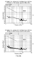
- Figure 9A shows the electromagnetic interference within the band 150kHz to 30MHz for the device 100 in operation at +28V DC on the master line.
- Figure 9A (1) shows the EMI when the device is operational
- Figure 9A (2) shows the EMI when the device is not operational.
- the EMI with the device 100 switched on is well below the permitted level marked by the dotted line 905A.
- Figure 9B shows the electromagnetic interference within the band 150kHz to 30MHz for the device 100 in operation at 0V on the master line.
- Figure 9B (1) shows the EMI when the device is operational
- Figure 9B (2) shows the EMI when the device is not operational.
- the EMI with the device 100 switched on is well below the permitted level marked by the dotted line 905B.
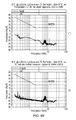
- Figure 9C shows the electromagnetic interference within the band 150kHz to 6GHz for the device 100 in operation.
- Figure 9C (1) shows the EMI when the device is operational
- Figure 9C (2) shows the EMI when the device is not operational.
- the EMI with the device 100 switched on is well below the permitted level marked by the dotted line 905C.
- the pulse width modulator switch 115 being connected to a light assembly
- the invention is no way limited to this.
- the device 100 may be connected to any external electrical device.
- the device 100 may instead have analogue components to control the pulse width modulator switch 115. This would further reduce electromagnetic interference because the digital controller 110 requires a clock which operates using a pulse train having substantially vertical rising and falling edges. However, it is envisaged that the clock may be disabled during periods of inactivity and may be enabled in response to an interrupt or after a predetermined period of time elapses. This is explained in relation to Figure 8 .
- the device 100 will be sealed by the manufacturer. This stops unauthorised tampering and is a safety feature. Again, for safety, it is desirable for the controller 110 to contain brownout detection circuitry which monitors the power supply. If the internal processor supply (which is normally 5V) drops below 4.64V, the system will automatically shut down safely. In the case of a shut-down, a power cycle will re-initialise the device 100. This brown-out detection circuitry ensures the controller 110 will shut down safely as the controller 110 can operate down to 2.7V.
- the pulse width modulator described above can be used to power any device located within an aircraft and not just the lighting system.
- the pulse width modulator can be used to power the motors within seats.
- look up table described hereinbefore is only an example and any appropriate values can be used depending on the application of the pulse width modulator. This would be appreciated by the skilled person.
Landscapes
- Engineering & Computer Science (AREA)
- Power Engineering (AREA)
- Physics & Mathematics (AREA)
- Electromagnetism (AREA)
- Circuit Arrangement For Electric Light Sources In General (AREA)
- Electronic Switches (AREA)
Applications Claiming Priority (1)
| Application Number | Priority Date | Filing Date | Title |
|---|---|---|---|
| GB1410111.7A GB2526882A (en) | 2014-06-06 | 2014-06-06 | Pulse width modulator for use in aviation |
Publications (2)
| Publication Number | Publication Date |
|---|---|
| EP2953264A2 true EP2953264A2 (de) | 2015-12-09 |
| EP2953264A3 EP2953264A3 (de) | 2016-06-01 |
Family
ID=51266838
Family Applications (1)
| Application Number | Title | Priority Date | Filing Date |
|---|---|---|---|
| EP15170812.0A Withdrawn EP2953264A3 (de) | 2014-06-06 | 2015-06-05 | Pulsbreitenmodulator für luftfahrtanwendung |
Country Status (3)
| Country | Link |
|---|---|
| US (1) | US20150358002A1 (de) |
| EP (1) | EP2953264A3 (de) |
| GB (1) | GB2526882A (de) |
Families Citing this family (9)
| Publication number | Priority date | Publication date | Assignee | Title |
|---|---|---|---|---|
| US10202194B2 (en) * | 2016-05-11 | 2019-02-12 | The Boeing Company | Tuned aircraft lighting for an improved flight experience |
| US12409756B2 (en) | 2017-04-05 | 2025-09-09 | H55 Sa | Aircraft monitoring system and method for electric or hybrid aircrafts |
| US11063323B2 (en) | 2019-01-23 | 2021-07-13 | H55 Sa | Battery module for electrically-driven aircraft |
| US11148819B2 (en) | 2019-01-23 | 2021-10-19 | H55 Sa | Battery module for electrically-driven aircraft |
| US11065979B1 (en) | 2017-04-05 | 2021-07-20 | H55 Sa | Aircraft monitoring system and method for electric or hybrid aircrafts |
| US10479223B2 (en) | 2018-01-25 | 2019-11-19 | H55 Sa | Construction and operation of electric or hybrid aircraft |
| US10854866B2 (en) | 2019-04-08 | 2020-12-01 | H55 Sa | Power supply storage and fire management in electrically-driven aircraft |
| CN108848600B (zh) * | 2018-09-25 | 2020-12-04 | 开源集成电路(苏州)有限公司 | 应用于led矩阵的pwm输出方法、系统、装置及存储介质 |
| CN114812728A (zh) * | 2021-01-19 | 2022-07-29 | 波音公司 | 确定储存箱的容量的系统和方法 |
Family Cites Families (7)
| Publication number | Priority date | Publication date | Assignee | Title |
|---|---|---|---|---|
| KR19990062405A (ko) * | 1997-12-03 | 1999-07-26 | 홍성표 | 발광 다이오드의 구동회로 및 구동방법 |
| WO2006083934A2 (en) * | 2005-02-01 | 2006-08-10 | B/E Aerospace, Inc. | Lighting system and method and apparatus for adjusting same |
| US7675248B2 (en) * | 2007-06-01 | 2010-03-09 | Honeywell International Inc. | Dual mode searchlight dimming controller systems and methods |
| EP2068599B1 (de) * | 2007-12-03 | 2011-04-27 | Sirio Panel S.P.A. | Schaltungsanordnung zur Erzeugung eines impulsbreitenmodulierten Signals zum Antreiben elektrischer Lasten |
| CA2659138C (en) * | 2008-03-20 | 2016-05-17 | Sirio Panel S.P.A. | Lighting system for avionics applications and control method thereof |
| TW201109908A (en) * | 2009-09-04 | 2011-03-16 | Leadtrend Tech Corp | Power management integrated circuit and power management method |
| KR101020597B1 (ko) * | 2010-03-03 | 2011-03-09 | 주식회사 라이트그린컨셉 | Led 조명 구동 장치 |
-
2014
- 2014-06-06 GB GB1410111.7A patent/GB2526882A/en not_active Withdrawn
-
2015
- 2015-06-05 EP EP15170812.0A patent/EP2953264A3/de not_active Withdrawn
- 2015-06-05 US US14/732,464 patent/US20150358002A1/en not_active Abandoned
Also Published As
| Publication number | Publication date |
|---|---|
| US20150358002A1 (en) | 2015-12-10 |
| GB2526882A (en) | 2015-12-09 |
| GB201410111D0 (en) | 2014-07-23 |
| EP2953264A3 (de) | 2016-06-01 |
Similar Documents
| Publication | Publication Date | Title |
|---|---|---|
| EP2953264A2 (de) | Pulsbreitenmodulator für luftfahrtanwendung | |
| US20250193982A1 (en) | Systems and methods for bleeder control related to triac dimmers associated with led lighting | |
| US9307593B1 (en) | Dynamic bleeder current control for LED dimmers | |
| US12396079B2 (en) | Systems and methods for controlling currents flowing through light emitting diodes | |
| CN103024994B (zh) | 使用triac调光器的调光控制系统和方法 | |
| EP2456285B1 (de) | Verfahren zur Steuerung eines elektronischen Ballasts, elektronischer Ballast und Beleuchtungssteuergerät | |
| EP2420110B1 (de) | Dimmer-steuerschaltung zum auswählen zwischen schritt-dimmmodus und phasenanschnitt-dimmmodus | |
| US9326343B2 (en) | Integrated LED dimmer controller | |
| CN104066254A (zh) | 使用triac调光器进行智能调光控制的系统和方法 | |
| US11812529B2 (en) | Eliminating flicker and open load protection for driver compatible with NAFTA dim ECG | |
| US20160095174A1 (en) | Led driver circuit with open load detection | |
| EP1842181B1 (de) | Antriebsvorrichtung für eine lichtemittierende diode mit hoher leistung und weitem verdunkelungsbereich | |
| US7957112B2 (en) | Protection circuit for limiting operating power of electrical device and method thereof | |
| US20160212816A1 (en) | Light emitting diode driver | |
| CN105007662A (zh) | Led照明灯及其双电源开关调色温控制电路 | |
| US9220145B2 (en) | Transformer voltage detection in dimmable lighting systems | |
| CA3165758A1 (en) | Control circuit for tubular light emitting diode | |
| EP2950620A2 (de) | Universeller digitaler dimmer | |
| US20130063031A1 (en) | Control Apparatus for a Circuit Arrangement for Operating a Light Source, as well as a System Comprising a Circuit Arrangement and a Circuit Arrangement, as well as a Method for Operating a Light Source | |
| KR20220090722A (ko) | 지능형 조명등 제어 장치 및 방법 | |
| US9974126B2 (en) | Control system of an electrical load | |
| KR101842483B1 (ko) | 개폐서지를 방지할 수 있는 ac직결형 led조명 시스템 | |
| US20100231141A1 (en) | Driving circuit for led | |
| JP6283908B2 (ja) | 照明器具 | |
| WO2015081367A1 (en) | A two-wire trailing edge control dimmer arrangement and a method for control dimming thereof |
Legal Events
| Date | Code | Title | Description |
|---|---|---|---|
| PUAI | Public reference made under article 153(3) epc to a published international application that has entered the european phase |
Free format text: ORIGINAL CODE: 0009012 |
|
| AK | Designated contracting states |
Kind code of ref document: A2 Designated state(s): AL AT BE BG CH CY CZ DE DK EE ES FI FR GB GR HR HU IE IS IT LI LT LU LV MC MK MT NL NO PL PT RO RS SE SI SK SM TR |
|
| AX | Request for extension of the european patent |
Extension state: BA ME |
|
| PUAL | Search report despatched |
Free format text: ORIGINAL CODE: 0009013 |
|
| AK | Designated contracting states |
Kind code of ref document: A3 Designated state(s): AL AT BE BG CH CY CZ DE DK EE ES FI FR GB GR HR HU IE IS IT LI LT LU LV MC MK MT NL NO PL PT RO RS SE SI SK SM TR |
|
| AX | Request for extension of the european patent |
Extension state: BA ME |
|
| RIC1 | Information provided on ipc code assigned before grant |
Ipc: H03K 7/08 20060101ALI20160428BHEP Ipc: H03K 4/94 20060101AFI20160428BHEP Ipc: H05B 33/08 20060101ALI20160428BHEP Ipc: H03K 3/017 20060101ALI20160428BHEP Ipc: B64D 11/00 20060101ALN20160428BHEP |
|
| STAA | Information on the status of an ep patent application or granted ep patent |
Free format text: STATUS: THE APPLICATION HAS BEEN PUBLISHED |
|
| 18D | Application deemed to be withdrawn |
Effective date: 20161202 |
|
| STAA | Information on the status of an ep patent application or granted ep patent |
Free format text: STATUS: THE APPLICATION IS DEEMED TO BE WITHDRAWN |