EP2953654B1 - Dispositif de stérilisation et procédé de stérilisation avec récupération d'énergie - Google Patents
Dispositif de stérilisation et procédé de stérilisation avec récupération d'énergie Download PDFInfo
- Publication number
- EP2953654B1 EP2953654B1 EP14700813.0A EP14700813A EP2953654B1 EP 2953654 B1 EP2953654 B1 EP 2953654B1 EP 14700813 A EP14700813 A EP 14700813A EP 2953654 B1 EP2953654 B1 EP 2953654B1
- Authority
- EP
- European Patent Office
- Prior art keywords
- fluid circuit
- cooling
- fluid
- heat exchanger
- circuit
- Prior art date
- Legal status (The legal status is an assumption and is not a legal conclusion. Google has not performed a legal analysis and makes no representation as to the accuracy of the status listed.)
- Active
Links
Images
Classifications
-
- A—HUMAN NECESSITIES
- A61—MEDICAL OR VETERINARY SCIENCE; HYGIENE
- A61L—METHODS OR APPARATUS FOR STERILISING MATERIALS OR OBJECTS IN GENERAL; DISINFECTION, STERILISATION OR DEODORISATION OF AIR; CHEMICAL ASPECTS OF BANDAGES, DRESSINGS, ABSORBENT PADS OR SURGICAL ARTICLES; MATERIALS FOR BANDAGES, DRESSINGS, ABSORBENT PADS OR SURGICAL ARTICLES
- A61L2/00—Disinfection or sterilisation of materials or objects, in general; Accessories therefor
- A61L2/02—Disinfection or sterilisation of materials or objects, in general; Accessories therefor using physical processes
- A61L2/04—Heat
- A61L2/06—Hot gas
- A61L2/07—Steam
-
- A—HUMAN NECESSITIES
- A61—MEDICAL OR VETERINARY SCIENCE; HYGIENE
- A61L—METHODS OR APPARATUS FOR STERILISING MATERIALS OR OBJECTS IN GENERAL; DISINFECTION, STERILISATION OR DEODORISATION OF AIR; CHEMICAL ASPECTS OF BANDAGES, DRESSINGS, ABSORBENT PADS OR SURGICAL ARTICLES; MATERIALS FOR BANDAGES, DRESSINGS, ABSORBENT PADS OR SURGICAL ARTICLES
- A61L2/00—Disinfection or sterilisation of materials or objects, in general; Accessories therefor
- A61L2/02—Disinfection or sterilisation of materials or objects, in general; Accessories therefor using physical processes
- A61L2/04—Heat
-
- F—MECHANICAL ENGINEERING; LIGHTING; HEATING; WEAPONS; BLASTING
- F28—HEAT EXCHANGE IN GENERAL
- F28D—HEAT-EXCHANGE APPARATUS, NOT PROVIDED FOR IN ANOTHER SUBCLASS, IN WHICH THE HEAT-EXCHANGE MEDIA DO NOT COME INTO DIRECT CONTACT
- F28D20/00—Heat storage plants or apparatus in general; Regenerative heat-exchange apparatus not covered by groups F28D17/00 or F28D19/00
- F28D20/0034—Heat storage plants or apparatus in general; Regenerative heat-exchange apparatus not covered by groups F28D17/00 or F28D19/00 using liquid heat storage material
- F28D20/0039—Heat storage plants or apparatus in general; Regenerative heat-exchange apparatus not covered by groups F28D17/00 or F28D19/00 using liquid heat storage material with stratification of the heat storage material
Definitions
- the present invention relates to an apparatus and method for sterilizing products with hot water and / or superheated steam.
- the terminal sterilization in particular the H adoptedbergberieselung, is usually quite large, for example, with a volume of about 5m 3 , executed in order to sterilize the largest possible amount of products per run can.
- the running time can be influenced by the amount of available media, the size of the heat exchangers and the available temperature of the heating or cooling media.
- the design of these components depends on the loading density, the product and the required process duration, but also on the size and mass of the sterilizer, which must be co-heated or co-cooled. With the ongoing cooling and heating of the sterilization device is associated with a very high energy consumption.
- a sterilization device comprising at least one chamber for sterilizing products and a primary fluid circuit connected to the chamber.
- the primary fluid circuit serves to pressurize the chamber or the products with hot water and / or superheated steam.
- the sterilization device comprises a secondary fluid circuit and a second Heat exchanger.
- the secondary fluid circuit is connected via the second heat exchanger with the primary fluid circuit, so that by means of the secondary fluid circuit of the primary fluid circuit can be heated and / or cooled.
- the sterilization device comprises a stratified storage tank in the secondary fluid circuit.
- the stratified storage tank comprises a plurality of temperature zones, the individual temperature zones being separately loadable and dischargeable with the fluid of the secondary fluid circuit.
- heat is withdrawn from the primary fluid circuit by means of the second heat exchanger.
- a heating of the fluid takes place in the secondary fluid circuit.
- This heat can be stored in the temperature zones of the stratified storage tank.
- the heat is removed from the stratified storage tank again and can be transferred via the second heat exchanger to the primary fluid circuit.
- the individual temperature zones of the stratified storage tank make it possible to store fluid at various temperatures.
- the primary fluid circuit By mixing together or stratified removal of the fluid from the individual temperature zones, the primary fluid circuit is assisted to be heated or cooled to the desired temperature.
- the primary fluid circuit preferably comprises a first heat exchanger.
- the first heat exchanger is connected to an independent heating and cooling line, so that the primary fluid circuit can also be operated independently of the secondary fluid circuit.
- a third heat exchanger is provided.
- This third heat exchanger is used for additional cooling of the fluid in the secondary fluid circuit, wherein the third heat exchanger is connected to an external cooling circuit.
- the third heat exchanger is integrated in the stratified storage tank.
- the third heat exchanger is installed in the temperature zone with the lowest temperature, ie in particular the lowest temperature zone.
- the stratified storage tank comprises in each case a separate, controllable connection to the temperature zones. Fluid can be loaded and unloaded directly into the individual temperature zones via this controllable connection.
- the controllable connections thus serve in the removal of fluid from the stratified storage tank for mixing together the desired temperature or for stratified removal. When loading the stratified storage tank, the fluid is directed via the controllable connections into the correct temperature zone.
- the stratified storage tank is designed in particular for receiving a fluid column.
- the different temperature zones are arranged one above the other or side by side in the fluid column.
- separation devices are provided in the stratified storage tank. These separators do not necessarily have to completely separate the individual temperature zones from each other. First and foremost, the separation devices serve to avoid a turbulent mixing of the fluid of different temperature zones.
- the stratified storage tank comprises at least three, preferably at least four temperature zones, which can be loaded and unloaded separately.
- the secondary fluid circuit with a stratified storage tank it is also possible to supply a plurality of chambers, each with a primary fluid circuit.
- a second heat exchanger is provided per primary fluid circuit, which is connected to the secondary fluid circuit.
- control device which controls and / or regulates the volume flow in the individual fluid lines, in particular in the connections of the layer storage tank.
- the invention further comprises a sterilization method comprising the steps of: (i) sterilizing products in a chamber with hot water and / or superheated steam from a primary fluid circuit, (ii) optionally heating or cooling the primary fluid circuit with a secondary fluid circuit, and (iii ) Storing the fluid of the second fluid circuit in different temperature zones.
- the fluid of the secondary fluid circuit from the different temperature zones is mixed together or removed in layers. Accordingly, it is also preferably provided that a return coming from the second heat exchanger is divided up correspondingly to the different temperature zones.
- the stored fluid preferably in the temperature zone with the lowest temperature, can be additionally cooled by means of a cooling circuit.
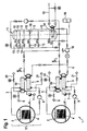
- Fig. 1 shows a circuit diagram of a sterilization device 1 according to the embodiment.
- the sterilization device 1 comprises a chamber 2. In this chamber 2, products 4 to be sterilized are arranged.
- the chamber 2 is connected to a primary fluid circuit 3.
- the fluid is conveyed by means of a first pump 9 and by means of a heat exchanger 19 is heated or cooled.
- the products 4 are sprinkled in the chamber with hot water.
- a steam inlet 6, a cooling medium supply line 20, a cooling medium return line 21 and a condensate drain 7 are formed.
- a second heat exchanger 5 is provided.
- the second heat exchanger 5 connects the primary fluid circuit 3 with a secondary fluid circuit 8.
- the secondary fluid circuit 8 serves to heat and cool the primary fluid circuit 3. This heat exchange takes place via the second heat exchanger 5.
- the fluid, preferably water, in the secondary fluid circuit 8 is conveyed by means of a second pump 10.
- This pump can be individually regulated in its performance.
- the secondary fluid circuit 8 further comprises a stratified storage tank 11.
- a stratified storage tank 11 In this stratified storage tank 11 there is a fluid column, which is subdivided into different temperature zones 12 arranged one above the other or next to one another. Individual connections 13 lead to the temperature zones 12.
- the individual temperature zones 12 of the stratified storage tank 11 can be loaded and unloaded via these connections 13.
- the connections 13 for this purpose include shut-off valves or mixing valves, which are controlled or regulated by a control device.
- the fluid for the secondary fluid circuit 8 can be mixed together or stratified to the corresponding temperature. As a result, targeted heating and cooling of the primary fluid circuit 3 via the second heat exchanger 5 is possible.
- a third heat exchanger 14 is provided.
- the third heat exchanger 14 is in the Layer storage tank 11, in particular in the lowest temperature zone 12, integrated.
- the third heat exchanger 14 is connected to an external cooling circuit 15.
- a pressure compensation device 16 is provided in the secondary fluid circuit 8.
- FIG. 1 shows a further arrangement 17, which also has a primary fluid circuit 3, a chamber 2 and a first heat exchanger 19. To the secondary fluid circuit 8 more of these other arrangements 17 can be connected.
- a heater such as a boiler, for additional heating of the secondary fluid circuit 8.
- full energy is required for heating the chamber 2.
- the water temperature in the primary fluid circuit 8 is about 121 ° C. in the sterilization phase.
- the stratified storage tank 11 is always filled with the fluid of the second fluid circuit 8, in particular with water, wherein the temperature of the fluid rises from bottom to top.
- the separation devices 18 in the stratified storage tank 11 prevent rapid mixing of the individual temperature zones.
- the fluid of the secondary fluid circuit 8 is heated by the hot process water in the primary fluid circuit 3.
- the energy from the primary fluid circuit 3 is thus transferred via the second heat exchanger 5 to the secondary fluid circuit 8 and can be stored in the stratified storage tank 11.
- the hot fluid in the secondary fluid circuit 8 is loaded into the stratified storage tank 11 via the various ports 13 depending on the temperature from the top.
- the lowermost temperature zone 12 is cooled with the third heat exchanger 14. This serves to ensure that the primary fluid circuit 3 can be cooled as quickly as possible.
- the hot fluid is removed in layers from the stratified storage tank 11. This happens in layers until no more positive energy input into the primary fluid circuit 3 can be made. From this point on, the primary fluid circuit 3 is further heated via the steam line 6 until the target temperature is reached.
- the efficiency is higher, since the third heat exchanger 14 in the stratified storage tank 11 additionally has a supporting effect.
- the energy consumption for the third heat exchanger 14 is less than the energy required in the conventional cooling process. It is possible to cool only via the third heat exchanger 14 and the stratified storage tank 11 or in addition via the cooling medium supply line 20, which has the additional advantage of being able to switch to another when one system fails.
- all energy is removed from the primary fluid circuit 3 via a cooling water system, usually a closed cooling circuit.
- the cooling water system itself is in turn cooled by cooling units or cooling towers.
- the shown sterilization device 1 and the associated sterilization method can be used for a wide variety of chambers 2.
- An intelligent control ensures that the stratified storage tank 11 is always full. When fluid is withdrawn from a temperature zone 12, fluid is simultaneously pumped to another temperature zone 12 so that the total volume in the stratified storage tank 11 remains the same.
- an intelligent control of the processes by means of controllable valves and temperature sensors in the casing, in the stratified storage tank 11, in the heat exchangers 5, 14, 19 and / or in the chamber 2 is preferably carried out.
Landscapes
- Health & Medical Sciences (AREA)
- Epidemiology (AREA)
- Life Sciences & Earth Sciences (AREA)
- Animal Behavior & Ethology (AREA)
- General Health & Medical Sciences (AREA)
- Public Health (AREA)
- Veterinary Medicine (AREA)
- Apparatus For Disinfection Or Sterilisation (AREA)
- Food Preservation Except Freezing, Refrigeration, And Drying (AREA)
Claims (10)
- Ensemble de stérilisation (1) comportant :- au moins une chambre (2) permettant de stériliser des produits (4),- un circuit primaire (3) de fluide raccordé à la chambre (2) et qui applique sur la chambre de l'eau chaude et/ou de la vapeur chaude,- un circuit secondaire (8) de fluide qui réchauffe et/ou refroidit le circuit primaire (3) de fluide, le circuit secondaire (8) de fluide étant raccordé au circuit primaire (3) de fluide par un deuxième échangeur de chaleur (5),caractérisé par- une cuve (11) d'accumulation stratifiée prévue dans le circuit secondaire (8) de fluide et présentant plusieurs zones de température (12), les zones de température (12) pouvant être chargées et déchargées séparément par le fluide du circuit secondaire (8).
- Ensemble de stérilisation selon la revendication 1, caractérisé par un troisième échangeur de chaleur (14) qui refroidit le fluide du circuit secondaire (8), le troisième échangeur de chaleur (14) étant raccordé à un circuit de refroidissement (15).
- Ensemble de stérilisation selon la revendication 2, caractérisé en ce que le troisième échangeur de chaleur (14) est intégré dans la cuve (11) à accumulation stratifiée, de préférence dans la zone de température (12) qui présente la température la plus basse.
- Ensemble de stérilisation selon l'une des revendications précédentes, caractérisé en ce que la cuve (11) d'accumulation stratifiée comporte pour chacune des différentes zones de température (12) un raccordement propre asservi (13) qui permet de charger et de décharger la zone de température (12) concernée.
- Ensemble de stérilisation selon l'une des revendications précédentes, caractérisé en ce que la cuve (11) d'accumulation stratifiée est formée pour reprendre une colonne de fluide, les zones de température (12) étant disposées les unes au-dessus des autres ou les unes à côté des autres dans la colonne de fluide.
- Ensemble de stérilisation selon la revendication 5, caractérisé en ce qu'au moins un ensemble de séparation (18) est disposé dans la cuve (11) d'accumulation stratifiée pour empêcher un mélange turbulent du fluide de différentes zones de température (12).
- Ensemble de stérilisation selon l'une des revendications précédentes, caractérisé en ce que la cuve (11) d'accumulation stratifiée comporte au moins trois et de préférence au moins quatre zones de température (12) qui peuvent être chargées et déchargées séparément au moyen de raccordements (13) distincts.
- Procédé de stérilisation recourant à un ensemble de stérilisation selon l'une des revendications précédentes et présentant les étapes suivantes :- stérilisation de produits (4) dans une chambre (2) à l'aide d'eau chaude et/ou de vapeur chaude provenant d'un circuit primaire (3) de fluide,- chauffage ou refroidissement sélectifs du circuit primaire (3) de fluide par un circuit secondaire (8) de fluide et- conservation du fluide du deuxième circuit (8) dans différentes zones de température (12).
- Procédé de stérilisation selon la revendication 8, caractérisé en ce que le fluide du circuit secondaire (8) provenant des différentes zones de température (12) est mélangé et/ou prélevé couche par couche pour chauffer et/ou refroidir le circuit primaire (3) de fluide.
- Procédé de stérilisation selon l'une des revendications 8 ou 9, caractérisé en ce que le fluide accumulé de préférence dans la zone de température (12) présentant la température la plus basse peut être refroidi au moyen d'un circuit de refroidissement (15).
Applications Claiming Priority (2)
| Application Number | Priority Date | Filing Date | Title |
|---|---|---|---|
| DE201310202188 DE102013202188A1 (de) | 2013-02-11 | 2013-02-11 | Sterilisationsvorrichtung und Sterilisationsverfahren mit Energierückgewinnung |
| PCT/EP2014/050033 WO2014121953A1 (fr) | 2013-02-11 | 2014-01-03 | Dispositif de stérilisation et procédé de stérilisation avec récupération d'énergie |
Publications (2)
| Publication Number | Publication Date |
|---|---|
| EP2953654A1 EP2953654A1 (fr) | 2015-12-16 |
| EP2953654B1 true EP2953654B1 (fr) | 2016-10-26 |
Family
ID=49998221
Family Applications (1)
| Application Number | Title | Priority Date | Filing Date |
|---|---|---|---|
| EP14700813.0A Active EP2953654B1 (fr) | 2013-02-11 | 2014-01-03 | Dispositif de stérilisation et procédé de stérilisation avec récupération d'énergie |
Country Status (5)
| Country | Link |
|---|---|
| US (1) | US9566356B2 (fr) |
| EP (1) | EP2953654B1 (fr) |
| CN (1) | CN104968369B (fr) |
| DE (1) | DE102013202188A1 (fr) |
| WO (1) | WO2014121953A1 (fr) |
Families Citing this family (7)
| Publication number | Priority date | Publication date | Assignee | Title |
|---|---|---|---|---|
| DE102014112366A1 (de) | 2014-08-28 | 2016-03-03 | Krones Ag | Anordnung und Verfahren zur Wärmespeicherung für Wärmeverbraucher in einer Anlage zur Getränkeherstellung und Brauereianlage |
| ITUD20150064A1 (it) * | 2015-05-08 | 2016-11-08 | Icos Pharma S P A | Apparato per la gestione di flussi caldi da una macchina di sterilizzazione di oggetti comprendente tale apparato e relativi metodi di gestione di flussi caldi e di sterilizzazione |
| CN109200297B (zh) * | 2018-09-03 | 2023-09-08 | 江苏新美星包装机械股份有限公司 | 喷淋冷却机 |
| FR3106198B1 (fr) | 2020-01-10 | 2022-01-14 | Commissariat Energie Atomique | Echangeur thermique partitionné, unité de valorisation d'énergie thermique et dispositif de stérilisation associé |
| FR3108394B1 (fr) | 2020-03-20 | 2022-12-23 | Commissariat Energie Atomique | Unité de valorisation, dispositif de stérilisation comprenant l'unité de valorisation et procédé associé. |
| CN112274659A (zh) * | 2020-10-15 | 2021-01-29 | 西安医学院 | 一种分子生物学用的实验器具高温杀菌装置 |
| JP7739872B2 (ja) * | 2021-09-06 | 2025-09-17 | 三浦工業株式会社 | 処理装置 |
Family Cites Families (9)
| Publication number | Priority date | Publication date | Assignee | Title |
|---|---|---|---|---|
| US4708849A (en) * | 1984-07-02 | 1987-11-24 | American Sterilizer Company | Process for energy storage and recovery |
| DE4312474C1 (de) * | 1993-04-16 | 1994-11-17 | Stiefenhofer Gmbh C | Dampfsterilisator mit Wärmerückgewinnung |
| DE4442709C2 (de) * | 1994-12-01 | 1997-12-18 | Stock Hermann Maschinenfabrik | Verfahren zum Sterilisieren und nachfolgenden Abkühlen von in Dosen, Gläsern oder anderen Konservierungsbehältern verpackten Lebensmitteln |
| EP0724014A3 (fr) * | 1995-01-25 | 1999-06-02 | Bernhard Lenz | Procédé et appareil pour le refroidissement de l'eau de brassage |
| CN100369634C (zh) * | 2003-09-26 | 2008-02-20 | 林刚毅 | 一种组合式节能灭菌釜以及利用这种灭菌釜节能的方法 |
| DE102007054429A1 (de) * | 2007-11-13 | 2009-05-14 | Krones Ag | Brauverfahren und Brauereianlagen |
| KR101246416B1 (ko) * | 2008-06-18 | 2013-03-21 | 가부시키가이샤 고베 세이코쇼 | 고압 처리 장치 |
| AT510578B1 (de) * | 2010-11-22 | 2012-05-15 | Vaillant Group Austria Gmbh | Schichtenspeicher |
| DE102010060919A1 (de) * | 2010-12-01 | 2012-06-06 | Schmidmeier Naturenergie Gmbh | Vorrichtung und Verfahren zur dampflosen Pasteurisierung von abgefüllten Lebensmitteln |
-
2013
- 2013-02-11 DE DE201310202188 patent/DE102013202188A1/de not_active Withdrawn
-
2014
- 2014-01-03 US US14/766,548 patent/US9566356B2/en active Active
- 2014-01-03 EP EP14700813.0A patent/EP2953654B1/fr active Active
- 2014-01-03 WO PCT/EP2014/050033 patent/WO2014121953A1/fr not_active Ceased
- 2014-01-03 CN CN201480007857.4A patent/CN104968369B/zh active Active
Non-Patent Citations (1)
| Title |
|---|
| None * |
Also Published As
| Publication number | Publication date |
|---|---|
| US20150374864A1 (en) | 2015-12-31 |
| WO2014121953A1 (fr) | 2014-08-14 |
| CN104968369B (zh) | 2018-07-03 |
| US9566356B2 (en) | 2017-02-14 |
| EP2953654A1 (fr) | 2015-12-16 |
| DE102013202188A1 (de) | 2014-08-14 |
| CN104968369A (zh) | 2015-10-07 |
Similar Documents
| Publication | Publication Date | Title |
|---|---|---|
| EP2953654B1 (fr) | Dispositif de stérilisation et procédé de stérilisation avec récupération d'énergie | |
| EP2114465B1 (fr) | Dispositif de pasteurisation avec pompe à chaleur intégrée, et procédé correspondant | |
| EP3068237B1 (fr) | Procédé et installation de pasteurisation de produits dans des récipients | |
| DE102011055147B4 (de) | Verfahren zur Einspeisung von Wärmeenergie in ein in einer lebensmitteltechnischen Prozessanlage zu verarbeitendes Prozessmittel sowie Wärmeversorgungssystem dafür | |
| EP2336700B1 (fr) | Dispositif de stockage et son procédé de fonctionnement | |
| AT514997A1 (de) | Modulare Absorptionskältemaschine in Plattenbauweise | |
| DE2256514C3 (de) | Vorrichtung zum Sterilisieren und/ oder Kochen von gefüllten geschlossenen Behältern | |
| EP3020795A1 (fr) | Procede et dispositif de preparation du mout | |
| DE2632910C2 (de) | Verfahren zum Eindampfen von Flüssigkeiten, insbesondere von radioaktiven Abwässern | |
| EP0770333B1 (fr) | Dispositif de refroidissement et chauffage d'aliment fluide | |
| DE1299393B (de) | Warmwassererzeuger, insbesondere Heizwassererzeuger | |
| CH710735A1 (de) | Mehrstufige Destillationsanlage, Verfahren zum Betreiben einer solchen und Steuerung dafür. | |
| DE2808139A1 (de) | Verfahren zum temperieren von formen, insbesondere druckgiess-, spritzguss- o.dgl. formen und vorrichtung zur durchfuehrung des verfahrens | |
| DE202014105416U1 (de) | Vorrichtung zum Würzekochen | |
| DE102016115582A1 (de) | Verfahren zum thermischen Desinfizieren, insbesondere Sterilisieren, und zum anschließenden Abkühlen einer Zentrifuge | |
| EP2281467A2 (fr) | Procédé et dispositif de chauffage, notamment de produits hautement visqueux | |
| DE102007061136A1 (de) | Verfahren und Vorrichtung zur mehrstufigen Behandlung von dispersen Feststoffen | |
| DE102012105427B3 (de) | Verfahren und Anlage zur Verarbeitung eines feuchten, Kerogen enthaltenden Stoffstroms | |
| DE69205127T2 (de) | Gefriertrocknungsanlage. | |
| EP3597080B1 (fr) | Dispositif et procédé de traitement des denrées alimentaires disposés dans un récipient | |
| DE102009043923A1 (de) | Brauverfahren und Brauvorrichtung mit Verwendung eines Heißwasserkessels | |
| EP3527920A1 (fr) | Installation de brasserie et procédé d'accumulation de chaleur dans une installation de brasserie | |
| EP2908079A1 (fr) | Procédé de récupération d'énergie thermique lors de la vulcanisation d'un pneu de véhicule | |
| EP1795818A1 (fr) | Procédé pour préparer de l'eau chaude utilisant un chauffe-eau et un accumulateur stratifié | |
| DE1281657B (de) | Warmwassererzeuger mit vorzugsweise elektrisch beheiztem Waermespeicher |
Legal Events
| Date | Code | Title | Description |
|---|---|---|---|
| PUAI | Public reference made under article 153(3) epc to a published international application that has entered the european phase |
Free format text: ORIGINAL CODE: 0009012 |
|
| 17P | Request for examination filed |
Effective date: 20150911 |
|
| AK | Designated contracting states |
Kind code of ref document: A1 Designated state(s): AL AT BE BG CH CY CZ DE DK EE ES FI FR GB GR HR HU IE IS IT LI LT LU LV MC MK MT NL NO PL PT RO RS SE SI SK SM TR |
|
| AX | Request for extension of the european patent |
Extension state: BA ME |
|
| DAX | Request for extension of the european patent (deleted) | ||
| GRAP | Despatch of communication of intention to grant a patent |
Free format text: ORIGINAL CODE: EPIDOSNIGR1 |
|
| INTG | Intention to grant announced |
Effective date: 20160801 |
|
| GRAS | Grant fee paid |
Free format text: ORIGINAL CODE: EPIDOSNIGR3 |
|
| GRAA | (expected) grant |
Free format text: ORIGINAL CODE: 0009210 |
|
| AK | Designated contracting states |
Kind code of ref document: B1 Designated state(s): AL AT BE BG CH CY CZ DE DK EE ES FI FR GB GR HR HU IE IS IT LI LT LU LV MC MK MT NL NO PL PT RO RS SE SI SK SM TR |
|
| REG | Reference to a national code |
Ref country code: GB Ref legal event code: FG4D Free format text: NOT ENGLISH |
|
| REG | Reference to a national code |
Ref country code: CH Ref legal event code: EP |
|
| REG | Reference to a national code |
Ref country code: AT Ref legal event code: REF Ref document number: 839557 Country of ref document: AT Kind code of ref document: T Effective date: 20161115 |
|
| REG | Reference to a national code |
Ref country code: IE Ref legal event code: FG4D Free format text: LANGUAGE OF EP DOCUMENT: GERMAN |
|
| REG | Reference to a national code |
Ref country code: DE Ref legal event code: R096 Ref document number: 502014001794 Country of ref document: DE |
|
| REG | Reference to a national code |
Ref country code: SE Ref legal event code: TRGR |
|
| REG | Reference to a national code |
Ref country code: LT Ref legal event code: MG4D |
|
| PG25 | Lapsed in a contracting state [announced via postgrant information from national office to epo] |
Ref country code: LV Free format text: LAPSE BECAUSE OF FAILURE TO SUBMIT A TRANSLATION OF THE DESCRIPTION OR TO PAY THE FEE WITHIN THE PRESCRIBED TIME-LIMIT Effective date: 20161026 |
|
| REG | Reference to a national code |
Ref country code: NL Ref legal event code: MP Effective date: 20161026 |
|
| PG25 | Lapsed in a contracting state [announced via postgrant information from national office to epo] |
Ref country code: GR Free format text: LAPSE BECAUSE OF FAILURE TO SUBMIT A TRANSLATION OF THE DESCRIPTION OR TO PAY THE FEE WITHIN THE PRESCRIBED TIME-LIMIT Effective date: 20170127 Ref country code: LT Free format text: LAPSE BECAUSE OF FAILURE TO SUBMIT A TRANSLATION OF THE DESCRIPTION OR TO PAY THE FEE WITHIN THE PRESCRIBED TIME-LIMIT Effective date: 20161026 Ref country code: NO Free format text: LAPSE BECAUSE OF FAILURE TO SUBMIT A TRANSLATION OF THE DESCRIPTION OR TO PAY THE FEE WITHIN THE PRESCRIBED TIME-LIMIT Effective date: 20170126 |
|
| PG25 | Lapsed in a contracting state [announced via postgrant information from national office to epo] |
Ref country code: ES Free format text: LAPSE BECAUSE OF FAILURE TO SUBMIT A TRANSLATION OF THE DESCRIPTION OR TO PAY THE FEE WITHIN THE PRESCRIBED TIME-LIMIT Effective date: 20161026 Ref country code: RS Free format text: LAPSE BECAUSE OF FAILURE TO SUBMIT A TRANSLATION OF THE DESCRIPTION OR TO PAY THE FEE WITHIN THE PRESCRIBED TIME-LIMIT Effective date: 20161026 Ref country code: FI Free format text: LAPSE BECAUSE OF FAILURE TO SUBMIT A TRANSLATION OF THE DESCRIPTION OR TO PAY THE FEE WITHIN THE PRESCRIBED TIME-LIMIT Effective date: 20161026 Ref country code: HR Free format text: LAPSE BECAUSE OF FAILURE TO SUBMIT A TRANSLATION OF THE DESCRIPTION OR TO PAY THE FEE WITHIN THE PRESCRIBED TIME-LIMIT Effective date: 20161026 Ref country code: PL Free format text: LAPSE BECAUSE OF FAILURE TO SUBMIT A TRANSLATION OF THE DESCRIPTION OR TO PAY THE FEE WITHIN THE PRESCRIBED TIME-LIMIT Effective date: 20161026 Ref country code: BE Free format text: LAPSE BECAUSE OF NON-PAYMENT OF DUE FEES Effective date: 20170131 Ref country code: IS Free format text: LAPSE BECAUSE OF FAILURE TO SUBMIT A TRANSLATION OF THE DESCRIPTION OR TO PAY THE FEE WITHIN THE PRESCRIBED TIME-LIMIT Effective date: 20170226 Ref country code: NL Free format text: LAPSE BECAUSE OF FAILURE TO SUBMIT A TRANSLATION OF THE DESCRIPTION OR TO PAY THE FEE WITHIN THE PRESCRIBED TIME-LIMIT Effective date: 20161026 Ref country code: PT Free format text: LAPSE BECAUSE OF FAILURE TO SUBMIT A TRANSLATION OF THE DESCRIPTION OR TO PAY THE FEE WITHIN THE PRESCRIBED TIME-LIMIT Effective date: 20170227 |
|
| REG | Reference to a national code |
Ref country code: DE Ref legal event code: R097 Ref document number: 502014001794 Country of ref document: DE |
|
| PG25 | Lapsed in a contracting state [announced via postgrant information from national office to epo] |
Ref country code: SK Free format text: LAPSE BECAUSE OF FAILURE TO SUBMIT A TRANSLATION OF THE DESCRIPTION OR TO PAY THE FEE WITHIN THE PRESCRIBED TIME-LIMIT Effective date: 20161026 Ref country code: DK Free format text: LAPSE BECAUSE OF FAILURE TO SUBMIT A TRANSLATION OF THE DESCRIPTION OR TO PAY THE FEE WITHIN THE PRESCRIBED TIME-LIMIT Effective date: 20161026 Ref country code: RO Free format text: LAPSE BECAUSE OF FAILURE TO SUBMIT A TRANSLATION OF THE DESCRIPTION OR TO PAY THE FEE WITHIN THE PRESCRIBED TIME-LIMIT Effective date: 20161026 Ref country code: EE Free format text: LAPSE BECAUSE OF FAILURE TO SUBMIT A TRANSLATION OF THE DESCRIPTION OR TO PAY THE FEE WITHIN THE PRESCRIBED TIME-LIMIT Effective date: 20161026 Ref country code: CZ Free format text: LAPSE BECAUSE OF FAILURE TO SUBMIT A TRANSLATION OF THE DESCRIPTION OR TO PAY THE FEE WITHIN THE PRESCRIBED TIME-LIMIT Effective date: 20161026 |
|
| PG25 | Lapsed in a contracting state [announced via postgrant information from national office to epo] |
Ref country code: BG Free format text: LAPSE BECAUSE OF FAILURE TO SUBMIT A TRANSLATION OF THE DESCRIPTION OR TO PAY THE FEE WITHIN THE PRESCRIBED TIME-LIMIT Effective date: 20170126 Ref country code: SM Free format text: LAPSE BECAUSE OF FAILURE TO SUBMIT A TRANSLATION OF THE DESCRIPTION OR TO PAY THE FEE WITHIN THE PRESCRIBED TIME-LIMIT Effective date: 20161026 |
|
| PLBE | No opposition filed within time limit |
Free format text: ORIGINAL CODE: 0009261 |
|
| STAA | Information on the status of an ep patent application or granted ep patent |
Free format text: STATUS: NO OPPOSITION FILED WITHIN TIME LIMIT |
|
| PG25 | Lapsed in a contracting state [announced via postgrant information from national office to epo] |
Ref country code: MC Free format text: LAPSE BECAUSE OF FAILURE TO SUBMIT A TRANSLATION OF THE DESCRIPTION OR TO PAY THE FEE WITHIN THE PRESCRIBED TIME-LIMIT Effective date: 20161026 |
|
| 26N | No opposition filed |
Effective date: 20170727 |
|
| REG | Reference to a national code |
Ref country code: FR Ref legal event code: ST Effective date: 20170929 |
|
| PG25 | Lapsed in a contracting state [announced via postgrant information from national office to epo] |
Ref country code: FR Free format text: LAPSE BECAUSE OF NON-PAYMENT OF DUE FEES Effective date: 20170131 |
|
| REG | Reference to a national code |
Ref country code: IE Ref legal event code: MM4A |
|
| PG25 | Lapsed in a contracting state [announced via postgrant information from national office to epo] |
Ref country code: LU Free format text: LAPSE BECAUSE OF NON-PAYMENT OF DUE FEES Effective date: 20170103 Ref country code: SI Free format text: LAPSE BECAUSE OF FAILURE TO SUBMIT A TRANSLATION OF THE DESCRIPTION OR TO PAY THE FEE WITHIN THE PRESCRIBED TIME-LIMIT Effective date: 20161026 |
|
| REG | Reference to a national code |
Ref country code: BE Ref legal event code: MM Effective date: 20170131 |
|
| PG25 | Lapsed in a contracting state [announced via postgrant information from national office to epo] |
Ref country code: IE Free format text: LAPSE BECAUSE OF NON-PAYMENT OF DUE FEES Effective date: 20170103 |
|
| GBPC | Gb: european patent ceased through non-payment of renewal fee |
Effective date: 20180103 |
|
| PG25 | Lapsed in a contracting state [announced via postgrant information from national office to epo] |
Ref country code: MT Free format text: LAPSE BECAUSE OF FAILURE TO SUBMIT A TRANSLATION OF THE DESCRIPTION OR TO PAY THE FEE WITHIN THE PRESCRIBED TIME-LIMIT Effective date: 20161026 |
|
| PG25 | Lapsed in a contracting state [announced via postgrant information from national office to epo] |
Ref country code: GB Free format text: LAPSE BECAUSE OF NON-PAYMENT OF DUE FEES Effective date: 20180103 |
|
| PG25 | Lapsed in a contracting state [announced via postgrant information from national office to epo] |
Ref country code: HU Free format text: LAPSE BECAUSE OF FAILURE TO SUBMIT A TRANSLATION OF THE DESCRIPTION OR TO PAY THE FEE WITHIN THE PRESCRIBED TIME-LIMIT; INVALID AB INITIO Effective date: 20140103 |
|
| PG25 | Lapsed in a contracting state [announced via postgrant information from national office to epo] |
Ref country code: CY Free format text: LAPSE BECAUSE OF FAILURE TO SUBMIT A TRANSLATION OF THE DESCRIPTION OR TO PAY THE FEE WITHIN THE PRESCRIBED TIME-LIMIT Effective date: 20161026 |
|
| PG25 | Lapsed in a contracting state [announced via postgrant information from national office to epo] |
Ref country code: MK Free format text: LAPSE BECAUSE OF FAILURE TO SUBMIT A TRANSLATION OF THE DESCRIPTION OR TO PAY THE FEE WITHIN THE PRESCRIBED TIME-LIMIT Effective date: 20161026 |
|
| REG | Reference to a national code |
Ref country code: AT Ref legal event code: MM01 Ref document number: 839557 Country of ref document: AT Kind code of ref document: T Effective date: 20190103 |
|
| PG25 | Lapsed in a contracting state [announced via postgrant information from national office to epo] |
Ref country code: TR Free format text: LAPSE BECAUSE OF FAILURE TO SUBMIT A TRANSLATION OF THE DESCRIPTION OR TO PAY THE FEE WITHIN THE PRESCRIBED TIME-LIMIT Effective date: 20161026 |
|
| PG25 | Lapsed in a contracting state [announced via postgrant information from national office to epo] |
Ref country code: AT Free format text: LAPSE BECAUSE OF NON-PAYMENT OF DUE FEES Effective date: 20190103 |
|
| REG | Reference to a national code |
Ref country code: DE Ref legal event code: R082 Ref document number: 502014001794 Country of ref document: DE Representative=s name: DREISS PATENTANWAELTE PARTG MBB, DE Ref country code: DE Ref legal event code: R081 Ref document number: 502014001794 Country of ref document: DE Owner name: SBM SCHOELLER-BLECKMANN MEDIZINTECHNIK GESELLS, AT Free format text: FORMER OWNER: ROBERT BOSCH GMBH, 70469 STUTTGART, DE |
|
| PG25 | Lapsed in a contracting state [announced via postgrant information from national office to epo] |
Ref country code: AL Free format text: LAPSE BECAUSE OF FAILURE TO SUBMIT A TRANSLATION OF THE DESCRIPTION OR TO PAY THE FEE WITHIN THE PRESCRIBED TIME-LIMIT Effective date: 20161026 |
|
| REG | Reference to a national code |
Ref country code: CH Ref legal event code: PUE Owner name: SBM SCHOELLER-BLECKMANN MEDIZINTECHNIK GMBH, AT Free format text: FORMER OWNER: ROBERT BOSCH GMBH, DE |
|
| PGFP | Annual fee paid to national office [announced via postgrant information from national office to epo] |
Ref country code: CH Payment date: 20250201 Year of fee payment: 12 |
|
| REG | Reference to a national code |
Ref country code: CH Ref legal event code: U11 Free format text: ST27 STATUS EVENT CODE: U-0-0-U10-U11 (AS PROVIDED BY THE NATIONAL OFFICE) Effective date: 20260201 |
|
| PGFP | Annual fee paid to national office [announced via postgrant information from national office to epo] |
Ref country code: SE Payment date: 20260121 Year of fee payment: 13 |
|
| PGFP | Annual fee paid to national office [announced via postgrant information from national office to epo] |
Ref country code: DE Payment date: 20260120 Year of fee payment: 13 |
|
| PGFP | Annual fee paid to national office [announced via postgrant information from national office to epo] |
Ref country code: IT Payment date: 20260130 Year of fee payment: 13 |