EP2954814A1 - Saugwerkzeug für elektrischen reiniger und elektrischer reiniger damit - Google Patents
Saugwerkzeug für elektrischen reiniger und elektrischer reiniger damit Download PDFInfo
- Publication number
- EP2954814A1 EP2954814A1 EP15169759.6A EP15169759A EP2954814A1 EP 2954814 A1 EP2954814 A1 EP 2954814A1 EP 15169759 A EP15169759 A EP 15169759A EP 2954814 A1 EP2954814 A1 EP 2954814A1
- Authority
- EP
- European Patent Office
- Prior art keywords
- suction tool
- lid
- suction
- cleaned
- groove
- Prior art date
- Legal status (The legal status is an assumption and is not a legal conclusion. Google has not performed a legal analysis and makes no representation as to the accuracy of the status listed.)
- Withdrawn
Links
Images


Classifications
-
- A—HUMAN NECESSITIES
- A47—FURNITURE; DOMESTIC ARTICLES OR APPLIANCES; COFFEE MILLS; SPICE MILLS; SUCTION CLEANERS IN GENERAL
- A47L—DOMESTIC WASHING OR CLEANING; SUCTION CLEANERS IN GENERAL
- A47L9/00—Details or accessories of suction cleaners, e.g. mechanical means for controlling the suction or for effecting pulsating action; Storing devices specially adapted to suction cleaners or parts thereof; Carrying-vehicles specially adapted for suction cleaners
- A47L9/02—Nozzles
- A47L9/04—Nozzles with driven brushes or agitators
- A47L9/0405—Driving means for the brushes or agitators
- A47L9/0411—Driving means for the brushes or agitators driven by electric motor
-
- A—HUMAN NECESSITIES
- A47—FURNITURE; DOMESTIC ARTICLES OR APPLIANCES; COFFEE MILLS; SPICE MILLS; SUCTION CLEANERS IN GENERAL
- A47L—DOMESTIC WASHING OR CLEANING; SUCTION CLEANERS IN GENERAL
- A47L9/00—Details or accessories of suction cleaners, e.g. mechanical means for controlling the suction or for effecting pulsating action; Storing devices specially adapted to suction cleaners or parts thereof; Carrying-vehicles specially adapted for suction cleaners
- A47L9/02—Nozzles
-
- A—HUMAN NECESSITIES
- A47—FURNITURE; DOMESTIC ARTICLES OR APPLIANCES; COFFEE MILLS; SPICE MILLS; SUCTION CLEANERS IN GENERAL
- A47L—DOMESTIC WASHING OR CLEANING; SUCTION CLEANERS IN GENERAL
- A47L9/00—Details or accessories of suction cleaners, e.g. mechanical means for controlling the suction or for effecting pulsating action; Storing devices specially adapted to suction cleaners or parts thereof; Carrying-vehicles specially adapted for suction cleaners
- A47L9/02—Nozzles
- A47L9/04—Nozzles with driven brushes or agitators
- A47L9/0427—Gearing or transmission means therefor
- A47L9/0444—Gearing or transmission means therefor for conveying motion by endless flexible members, e.g. belts
Definitions
- the present invention relates to suction tools for electric cleaners and electric cleaners using the suction tool.
- a conventional suction tool for electric cleaner rotates a rotary brush typically by an electric motor to suck in dust through a suction port facing a surface to be cleaned.
- This type of suction tool for electric cleaner needs a space at an end portion of the suction tool for accommodating such an element as a belt, a pulley or the like which transmits power to the rotary brush. Therefore, the suction port cannot be provided over the full length in a longitudinal direction of the bottom surface of the suction tool for electric cleaner. The end portion of the suction tool thus becomes a suction dead space where the suction port cannot be extended. Thus, the end portion of the suction tool cannot suck in and remove dust on the surface to be cleaned.
- a suction tool having a structure in which brushes are provided at and fixed to both end portions of the bottom surface (facing the surface to be cleaned) of the suction tool is disclosed in PTL 1 (Japanese Patent Unexamined Publication No. 2011-36445 ).
- a space for accommodating a pulley or the like which transmits power to the rotary brush is needed at an end portion of the rotary cleaning body.
- no modification is applied to the structure in connection with this space.
- this space is kept and secured without any alteration being applied to the structure of the suction tool.
- PTL 1 only discloses the fixed brushes which are disposed in the suction dead space of the suction tool where the suction port cannot be provided.
- a suction port can be extended to an end portion of the bottom surface of the suction tool.
- the present invention provides a suction tool for electric cleaner that can suck in and remove dust even at the end portions of the bottom surface, facing a surface to be cleaned, of the suction tool.
- the suction tool for electric cleaner of the present invention includes a suction tool body having a suction port which has an opening facing the surface to be cleaned, a rotary brush rotatably provided in the suction tool body for scraping out the dust on the surface to be cleaned, an electric motor provided inside the suction tool body for driving the rotary brush, and a belt for transmitting a driving force of the electric motor to the rotary brush.
- the suction tool for electric cleaner of the present invention further includes a brush cover detachably provided on the bottom side of the suction tool body, an outer wall member provided on the brush cover and surrounding the suction port, and a lid provided on at least one end portion in the longitudinal direction of the brush cover for protecting the belt from external contact.
- a groove is formed by vertical surfaces (surfaces perpendicular to the surface to be cleaned) of the outer wall member and arc surfaces which are formed on the lid.
- the groove formed on the lid provides a channel space where the air flows through the end portion in the longitudinal direction of the bottom side of the suction tool body and through the surface to be cleaned.
- the structures of the present invention as described above enable to extend the suction port to an end portion in the longitudinal direction of the bottom side of the suction tool body, where a suction port is not successfully provided by the conventional technologies.
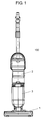
- Fig. 1 is a front view of an appearance of electric cleaner 100 having a suction tool 1 for electric cleaner 100 in the preferred embodiment of the present invention.
- cleaner body 3 includes a built-in electric blower for generating a suction airflow, dust chamber 2, and suction tool 1 for electric cleaner 100 (hereafter referred to as suction tool body 1).
- Fig. 2 is a plan view illustrating a state that brush cover 17 is detached from suction tool body 1.
- Fig. 3 is a plan view illustrating a state that brush cover 17 is attached to suction tool body 1.
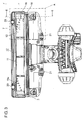
- Fig. 4 is a plan view of brush cover 17 seen from the bottom side (the side facing the surface to be cleaned) of suction tool body 1.
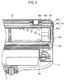
- Fig. 5 is a magnified view of Part A in Fig. 3 , illustrating a shape of groove 19 formed on lid 16 of brush cover 17.
- suction tool body 1 includes suction port 10 for sucking in dust, rotary brush 11 with brush 11a for scraping out dust, an electric motor for driving rotary brush 11, and belt 12 for transmitting a driving force from the electric motor to rotary brush 11.
- Brush cover 17 is detachably provided on the bottom side of suction tool body 1 so that rotary brush 11 can be removed for maintenance, such as for removing the dust that is wound around rotary brush 11.
- outer wall member 18 is provided on brush cover 17and is provided to surround suction port 10 of suction tool body 1.
- Each of the surfaces of outer wall member 18, which faces the surface to be cleaned, has a flat surface and is provided at substantially the same height in a direction vertical to the bottom side of suction tool body 1. More specifically, as shown in Fig. 5 , front outer wall 18a of brush cover 17, rear outer wall 18c of suction tool body 1, and side outer walls 18b on the left and right sides of brush cover 17 are connected to each other at substantially the same height in a direction vertical to the bottom side of suction tool body 1.
- Brush cover 17 has an opening inside outer wall member 18 surrounded by front outer wall 18a, rear outer wall 18c, and side outer walls 18b. This opening corresponds to an opening of suction port 10 of suction tool body 1.
- lid 16 for protecting belt 12 from being contacted by an external contact is provided at an end portion in the longitudinal direction of brush cover 17.
- wall 15 is provided in inside of lid 16 and is provided on the back side of the surface of lid 16 facing the surface to be cleaned. Also, wall 15 is provided to divide a space in the inside of lid 16 to accommodate rotary brush 11 and belt 12 in the divided spaces respectively.
- Suction tool body 1 in the preferred embodiment is configured to provide as minimum gap as possible between the bottom side of suction tool body 1 and the surface to be cleaned when suction tool body 1 is placed on the surface to be cleaned, and when front rollers 20 and rear rollers 21 come to contact with the surface to be cleaned.
- the gap between the flat surface of outer wall member 18 and the surface to be cleaned is set to have a predetermined clearance.
- outer wall member 18 faces the surface to be cleaned and is constituted by the flat surfaces of front outer wall 18a, rear outer wall 18c and side outer wall 18b.
- This predetermined clearance is set, for example, in a range of from 0.5 mm to 1.5 mm to prevent the surface to be cleaned from being damaged when the bottom side of suction tool body 1 is placed on the surface to be cleaned and comes to contact with the same.
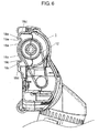
- Fig. 6 is a sectional view of lid 16 taken along Line 6-6 in Fig. 3 , showing a cross-sectional shape of lid 16.
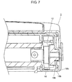
- Fig. 7 is a sectional view of lid 16 taken along Line 7-7 in Fig. 3 , showing another cross-sectional shape of lid 16.
- groove 19 is formed by lid 16 and outer wall member 18. More specifically, groove 19 is formed by groove 19a and groove 19c shown in the sectional view in Fig. 6 , and groove 19b shown in the sectional view in Fig. 7 . Groove 19a, groove 19c and groove 19b are connected to each other and form a substantially U-shape.
- a depth of groove 19, i.e., a position of groove 19 in the height direction (a direction perpendicular to the surface to be cleaned), is preferably set, although it depends on the shape of belt 12, for an upper end of groove 19 (an end furthest from the flat surface of outer wall member 18) to be located at a height in a range of from 3 mm to 8 mm in the direction away from the flat surface of outer wall member 18 facing the surface to be cleaned.
- lid 16 is designed so as to correspond to the shape of belt 12. More specifically, in the preferred embodiment, lid 16 is designed to have an arc shape which corresponds to the arc shape of belt 12.
- a clearance is provided between belt 12 and lid 16 to an extent not to at least obstruct the rotation of belt 12.
- the clearance is set to have as a minimum clearance as feasible so that lid 16 does not obstruct the rotation of belt 12.
- groove 19a and groove 19c are formed by arc-shaped surface 16a and arc-shaped surface 16c of lid 16 and vertical surface 18d (a surface perpendicular to the surface to be cleaned) of outer wall member 18.
- the shape of lid 16 is not limited to be an arc shape but can be other shapes as long as the clearance for preventing lid 16 from obstructing the rotation of belt 12 is secured. It is preferable that the shape of lid 16 is designed to provide the clearance by way of forming the grooves on lid 16, in which the grooves include groove 19a and groove 19c and are formed by vertical surface 18d of outer wall member 18 and the surface of lid 16 facing the surface to be cleaned.
- the surface of lid 16 facing the surface to be cleaned can be positioned up in a direction away from the surface to be cleaned, or away from the flat surface of outer wall member 18 facing the surface to be cleaned.
- the larger groove 19a and groove 19c can be formed.
- lid 16 has tilted surface 16b which is tilted in a direction away from the surface of lid 16 facing the surface to be cleaned (in a direction close to belt 12).
- Groove 19b is formed by tilted surface 16b of lid 16 and a vertical surface (a surface perpendicular to the surface to be cleaned) of side outer wall 18b.
- suction tool body 1 for electric cleaner 100 The operations and effects of suction tool body 1 for electric cleaner 100 in the preferred embodiment as configured above are now described below.
- suction airflow in suction tool body 1 reaches suction port 10 through the predetermined clearance between outer wall member 18 disposed on the bottom side (the side facing the surface to be cleaned) of suction tool body 1 and the surface to be cleaned.
- the suction airflow reaching suction port 10 passes through groove 19 formed on lid 16, and reaches rotary brush 11. Therefore, the suction airflow passing groove 19 functions as carrying the dust on the surface to be cleaned residing below lid 16 toward rotary brush 11. Accordingly, the dust located around the end portion in the longitudinal direction of suction tool body 1, such as a portion where lid 16 is provided in the preferred embodiment, and where it is conventionally difficult to remove the dust, can be removed. Lid 16 can thus function as suction port 10.
- groove 19 formed up with groove 19a, groove 19b, and groove 19c, in which groove 19a, groove 19b, and groove 19c are connected each other to form a substantially U-shape, is provided on the surface of lid 16 facing the surface to be cleaned.
- the depth of groove 19 is preferably set at a position in a range of from 3 mm to 8mm away from the surface of outer wall member 18 facing the surface to be cleaned in the height direction (a direction perpendicular to the surface to be cleaned).
- lid 16 has a shape corresponding to the shape of belt 12.
- lid 16 is formed to have an arc shape along with the arc shape of belt 12.
- belt 12 has an oval shape
- lid 16 is formed to have an oval shape along with the oval shape of belt 12.
- Arc-shaped surface 16a and arc-shaped surface 16c are provided on lid 16 to secure a clearance between belt 12 and lid 16 to prevent lid 16 from at least obstructing the rotation of belt 12.
- the clearance is provided to have a space as minimum as required for preventing lid 16 from obstructing the rotation of belt 12.
- This structure enables to form a large space in groove 19a and groove 19c without interference between the inner surface of lid 16 and belt 12.
- this structure enables to increase the amount of the suction airflow flowing through groove 19a and groove 19c.
- groove 19 is not limited to the substantially U-shape which, in the preferred embodiment, is formed by connecting groove 19a, groove 19c and groove 19b with each other.
- Groove 19 can be designed to have other shapes as long as the channel space for flowing the air is formed between lid 16 and the surface to be cleaned, a groove which provides a sufficient space for allowing the suction airflow to flow through this channel space is formed, and there is no interference to the operation of belt 12.
- suction tool body 1 for electric cleaner 100 includes suction tool body 1 with suction port 10 having an opening facing the surface to be cleaned, rotary brush 11 rotatably provided on suction tool body 1 for scraping out dust on the surface to be cleaned, an electric motor provided inside suction tool body 1 for driving the rotary brush 11, belt 12 transmitting a driving force of the electric motor to rotary brush 11, and brush cover 17 detachably provided on the bottom side of suction tool body 1.
- Suction tool body 1 for electric cleaner 100 in the preferred embodiment further includes outer wall member 18 provided on brush cover 17 for surrounding suction port 10, lid 16 provided around the end portion of brush cover 17 for protecting belt 12 from outer contact, and groove 19 formed on lid 16. Groove 19 forms a channel space where the air flows through suction tool body 1 and the surface to be cleaned, and the suction airflow flows this channel space.
- suction port 10 can be extended to end portions in the longer direction on the bottom side of suction tool body 1, where it is conventionally difficult to provide a suction port. Accordingly, dust on the surface to be cleaned below the end portions in the longitudinal direction of suction tool body 1 can be removed.
- suction tool body 1 for electric cleaner 100 can be produced at a low manufacturing cost, and also the cleaning efficiency of suction tool body 1 for electric cleaner 100 can be improved with a simple structure.
- lid 16 preferably has a shape which corresponds to the shape of belt 12, such as an arc shape.
- Lid 16 and belt 12 are provided in suction tool body 1 in such a way that a clearance between lid 16 and belt 12 for preventing lid 16 from obstructing the rotation of belt 12 is secured.
- the clearance has a minimum but sufficient space for preventing lid 16 from obstructing the rotation of belt 12.
- groove 19 is formed up with lid 16 and outer wall member 18.
- the above-described structures enable to form a large size of groove 19 without obstructing the rotation of belt 12 and to increase the amount of the suction airflow flowing through groove 19.
- dust on the surface to be cleaned below the end portion of suction tool body 1 can be sucked in.
- suction tool body 1 for electric cleaner 100 with high cleaning efficiency can be achieved.
- the preferred embodiment of the present invention enables to suck in and remove dust on the surface to be cleaned below the end portions in the longitudinal direction of suction tool body 1 without providing a fixed brush at the end portion of suction tool body 1, while securing a space for accommodating a belt or a pulley or the like.
- electric cleaner 100 having high dust-collecting capacity that can collect dust on the surface to be cleaned at a corner against a wall can also be achieved by connecting suction tool body 1 for electric cleaner 100 in the preferred embodiment with cleaner body 3 which has a built-in electric blower for generating suction airflow.
- the preferred embodiment of the present invention can achieve electric cleaner 100 that can remove dust on the surface to be cleaned below the end portions in the longitudinal direction of suction tool body 1 without providing a fixed brush, while securing a space for accommodating a belt or a pulley or the like.
- the above-described structures of the preferred embodiment of the present invention can provide electric cleaner 100 at a low manufacturing cost and can improve the cleaning efficiency of suction tool body 1 with a simple structure without providing an additional element such as a fixed brush used in a conventional suction tool.
- the present invention offers suction tool for electric cleaner and an electric cleaner using the suction tool that have a significant effect of sucking in and removing dust on the surface to be cleaned especially at the end portions of the suction tool body. Accordingly, the present invention is broadly applicable to home-use and industrial-use electric cleaners.
Landscapes
- Engineering & Computer Science (AREA)
- Mechanical Engineering (AREA)
- Nozzles For Electric Vacuum Cleaners (AREA)
Applications Claiming Priority (1)
| Application Number | Priority Date | Filing Date | Title |
|---|---|---|---|
| JP2014120183A JP6357645B2 (ja) | 2014-06-11 | 2014-06-11 | 電気掃除機用吸込具およびそれを用いた電気掃除機 |
Publications (1)
| Publication Number | Publication Date |
|---|---|
| EP2954814A1 true EP2954814A1 (de) | 2015-12-16 |
Family
ID=53284057
Family Applications (1)
| Application Number | Title | Priority Date | Filing Date |
|---|---|---|---|
| EP15169759.6A Withdrawn EP2954814A1 (de) | 2014-06-11 | 2015-05-29 | Saugwerkzeug für elektrischen reiniger und elektrischer reiniger damit |
Country Status (2)
| Country | Link |
|---|---|
| EP (1) | EP2954814A1 (de) |
| JP (1) | JP6357645B2 (de) |
Cited By (3)
| Publication number | Priority date | Publication date | Assignee | Title |
|---|---|---|---|---|
| CN106923747A (zh) * | 2017-04-25 | 2017-07-07 | 苏州市春菊电器有限公司 | 一种用于清洁器具的滚刷缠绕物切除装置及其清洁器具 |
| CN106923758A (zh) * | 2017-04-25 | 2017-07-07 | 苏州市春菊电器有限公司 | 一种用于切割清洁器具上滚刷缠绕物的刀具及其清洁器具 |
| EP4079205A1 (de) * | 2021-03-23 | 2022-10-26 | Arçelik Anonim Sirketi | Reinigungsroboter mit einem bürstendeckelverriegelungsmechanismus |
Families Citing this family (1)
| Publication number | Priority date | Publication date | Assignee | Title |
|---|---|---|---|---|
| ATE84856T1 (de) | 1989-04-26 | 1993-02-15 | Norton Pampus Gmbh | Wartungsfreies gleitlager und ein verfahren fuer seine herstellung. |
Citations (3)
| Publication number | Priority date | Publication date | Assignee | Title |
|---|---|---|---|---|
| GB2046087A (en) * | 1979-04-02 | 1980-11-12 | Hitachi Ltd | Vacuum cleaner |
| WO2006080383A1 (ja) * | 2005-01-31 | 2006-08-03 | Toshiba Tec Kabushiki Kaisha | 電気掃除機およびその吸込口体 |
| JP2011036445A (ja) | 2009-08-12 | 2011-02-24 | Hitachi Appliances Inc | 電気掃除機用吸口体及び電気掃除機 |
Family Cites Families (3)
| Publication number | Priority date | Publication date | Assignee | Title |
|---|---|---|---|---|
| JPS60149368U (ja) * | 1984-03-15 | 1985-10-03 | 三菱電機株式会社 | 掃除機用床ブラシ |
| JPS6179435A (ja) * | 1984-09-26 | 1986-04-23 | 松下電器産業株式会社 | 電機掃除機の床ノズル |
| JP3574000B2 (ja) * | 1999-04-05 | 2004-10-06 | 三洋電機株式会社 | 電気掃除機 |
-
2014
- 2014-06-11 JP JP2014120183A patent/JP6357645B2/ja active Active
-
2015
- 2015-05-29 EP EP15169759.6A patent/EP2954814A1/de not_active Withdrawn
Patent Citations (3)
| Publication number | Priority date | Publication date | Assignee | Title |
|---|---|---|---|---|
| GB2046087A (en) * | 1979-04-02 | 1980-11-12 | Hitachi Ltd | Vacuum cleaner |
| WO2006080383A1 (ja) * | 2005-01-31 | 2006-08-03 | Toshiba Tec Kabushiki Kaisha | 電気掃除機およびその吸込口体 |
| JP2011036445A (ja) | 2009-08-12 | 2011-02-24 | Hitachi Appliances Inc | 電気掃除機用吸口体及び電気掃除機 |
Cited By (5)
| Publication number | Priority date | Publication date | Assignee | Title |
|---|---|---|---|---|
| CN106923747A (zh) * | 2017-04-25 | 2017-07-07 | 苏州市春菊电器有限公司 | 一种用于清洁器具的滚刷缠绕物切除装置及其清洁器具 |
| CN106923758A (zh) * | 2017-04-25 | 2017-07-07 | 苏州市春菊电器有限公司 | 一种用于切割清洁器具上滚刷缠绕物的刀具及其清洁器具 |
| CN106923758B (zh) * | 2017-04-25 | 2018-06-29 | 苏州市春菊电器有限公司 | 一种用于切割清洁器具上滚刷缠绕物的刀具及其清洁器具 |
| CN106923747B (zh) * | 2017-04-25 | 2019-03-12 | 苏州市春菊电器有限公司 | 一种用于清洁器具的滚刷缠绕物切除装置及其清洁器具 |
| EP4079205A1 (de) * | 2021-03-23 | 2022-10-26 | Arçelik Anonim Sirketi | Reinigungsroboter mit einem bürstendeckelverriegelungsmechanismus |
Also Published As
| Publication number | Publication date |
|---|---|
| JP2016000064A (ja) | 2016-01-07 |
| JP6357645B2 (ja) | 2018-07-18 |
Similar Documents
| Publication | Publication Date | Title |
|---|---|---|
| EP3777628B1 (de) | Reinigerkopf und staubsauger damit | |
| EP2954814A1 (de) | Saugwerkzeug für elektrischen reiniger und elektrischer reiniger damit | |
| KR101641262B1 (ko) | 로봇 청소기 | |
| EP3686499A1 (de) | Filtersiebreinigungsmodul und luftbehandlungsvorrichtung | |
| JP2011111793A (ja) | 携帯用ブロワ | |
| JP5213570B2 (ja) | 電気掃除機 | |
| JP4538676B2 (ja) | ヘアカッター | |
| TW202203833A (zh) | 安裝在吸引式之吸塵器的吸入具 | |
| JP2016083310A (ja) | 携帯用掃除機 | |
| TWI600402B (zh) | Cleaning equipment, especially vacuum cleaner or vacuum cleaner attachment | |
| WO2012153460A1 (ja) | 電気掃除機用吸込具 | |
| JP7267867B2 (ja) | 掃除機用吸込具および電気掃除機 | |
| KR20050026166A (ko) | 진공청소기 | |
| JP4958168B2 (ja) | 掃除機用の吸入口体 | |
| EP2789282A1 (de) | Elektrischer staubsauger | |
| CN104825097A (zh) | 用于吸尘器的地刷及具有其的吸尘器 | |
| KR20200114574A (ko) | 충전식 전동공구의 송풍 및 흡입장치 | |
| CN1306901C (zh) | 吸尘器的吸尘设备 | |
| US20060090292A1 (en) | Brush assembly and a vacuum cleaner having the same | |
| JP5788746B2 (ja) | 電動工具用集塵装置及び電動工具 | |
| CN107898385B (zh) | 旋风分离器和具有其的吸尘器 | |
| US20240032748A1 (en) | Nozzle and cleaner | |
| KR102195271B1 (ko) | 전동드릴 장치 | |
| KR100397198B1 (ko) | 교환 가능한 진공청소기의 흡입구 커버구조 | |
| KR101192869B1 (ko) | 진공 청소기용 흡입구체 |
Legal Events
| Date | Code | Title | Description |
|---|---|---|---|
| PUAI | Public reference made under article 153(3) epc to a published international application that has entered the european phase |
Free format text: ORIGINAL CODE: 0009012 |
|
| AK | Designated contracting states |
Kind code of ref document: A1 Designated state(s): AL AT BE BG CH CY CZ DE DK EE ES FI FR GB GR HR HU IE IS IT LI LT LU LV MC MK MT NL NO PL PT RO RS SE SI SK SM TR |
|
| AX | Request for extension of the european patent |
Extension state: BA ME |
|
| 17P | Request for examination filed |
Effective date: 20160615 |
|
| RBV | Designated contracting states (corrected) |
Designated state(s): AL AT BE BG CH CY CZ DE DK EE ES FI FR GB GR HR HU IE IS IT LI LT LU LV MC MK MT NL NO PL PT RO RS SE SI SK SM TR |
|
| 17Q | First examination report despatched |
Effective date: 20180110 |
|
| STAA | Information on the status of an ep patent application or granted ep patent |
Free format text: STATUS: THE APPLICATION IS DEEMED TO BE WITHDRAWN |
|
| 18D | Application deemed to be withdrawn |
Effective date: 20180523 |