EP3686499A1 - Filtersiebreinigungsmodul und luftbehandlungsvorrichtung - Google Patents
Filtersiebreinigungsmodul und luftbehandlungsvorrichtung Download PDFInfo
- Publication number
- EP3686499A1 EP3686499A1 EP19798513.8A EP19798513A EP3686499A1 EP 3686499 A1 EP3686499 A1 EP 3686499A1 EP 19798513 A EP19798513 A EP 19798513A EP 3686499 A1 EP3686499 A1 EP 3686499A1
- Authority
- EP
- European Patent Office
- Prior art keywords
- filter screen
- roller
- inner shaft
- outer cylinder
- cleaning module
- Prior art date
- Legal status (The legal status is an assumption and is not a legal conclusion. Google has not performed a legal analysis and makes no representation as to the accuracy of the status listed.)
- Pending
Links
Images



Classifications
-
- F—MECHANICAL ENGINEERING; LIGHTING; HEATING; WEAPONS; BLASTING
- F24—HEATING; RANGES; VENTILATING
- F24F—AIR-CONDITIONING; AIR-HUMIDIFICATION; VENTILATION; USE OF AIR CURRENTS FOR SCREENING
- F24F8/00—Treatment, e.g. purification, of air supplied to human living or working spaces otherwise than by heating, cooling, humidifying or drying
- F24F8/90—Cleaning of purification apparatus
-
- F—MECHANICAL ENGINEERING; LIGHTING; HEATING; WEAPONS; BLASTING
- F24—HEATING; RANGES; VENTILATING
- F24F—AIR-CONDITIONING; AIR-HUMIDIFICATION; VENTILATION; USE OF AIR CURRENTS FOR SCREENING
- F24F1/00—Room units for air-conditioning, e.g. separate or self-contained units or units receiving primary air from a central station
- F24F1/0007—Indoor units, e.g. fan coil units
- F24F1/0071—Indoor units, e.g. fan coil units with means for purifying supplied air
- F24F1/0073—Indoor units, e.g. fan coil units with means for purifying supplied air characterised by the mounting or arrangement of filters
Definitions
- the present application pertains to the technical field of household appliance, and in particular, relates to a filter screen cleaning module and an air processing device.
- a filter In an air conditioner, usually, a filter is provided at an air inlet or an air outlet to filter. In the long-term use, much dust would be accumulated on the filter. It takes time and effort to remove and wash the filter manually, and a filter assembly is easily damaged.
- the present application seeks to solve at least one of the problems existing in the related art to at least some extent.
- an object of the present application is to provide a filter screen cleaning module which may stably drive the filter to move and wash, and has a roller assembly which is stable when rotated.
- Another object of the present application is to provide an air processing device having the above-mentioned filter screen cleaning module.
- the filter screen cleaning module includes: a cleaning box, having a cleaning cavity; a roller assembly, rollably connected between two opposite side walls of the cleaning box, and comprising: a roller inner shaft and a roller outer cylinder, wherein the roller inner shaft is fitted over the roller outer cylinder, a rotation limiting structure is provided between the roller outer cylinder and the roller inner shaft, and the roller outer cylinder is configured to contact a filter screen to drive the filter screen to move; and a roller drive gear, disposed on the cleaning box and connected with the roller assembly.
- the cleaning box provides an effective connection position for the roller assembly, such that the roller assembly is relatively stable and has a small offset when rolling.
- the roller inner shaft serves as a rotating shaft of the roller assembly.
- the roller outer cylinder on the rotating shaft may drive the filter to move, and also plays a role of cleaning the filter to some extent.
- the arrangement of the rotation limiting structure between the roller outer cylinder and the roller inner shaft may increase the limit therebetween effectively, avoid a circumferential displacement therebetween or an excessive friction force with the filter due to a large rotational speed, and stabilize the roller assembly when rolling as a whole.
- the roller drive gear is arranged separately from the roller assembly, which may increase the ease of assembly of the roller drive gear and the roller assembly, reduce the occupied space inside the cleaning box, and increase the available cleaning space of the filter.
- a rotation limiting groove is provided on an outer peripheral wall of the roller inner shaft
- a rotation limiting projection is provided on an inner peripheral wall of the roller outer cylinder
- the rotation limiting projection is inserted and fitted in the rotation limiting groove
- the roller inner shaft is formed in a hollow cylindrical shape, and a part of the peripheral wall of the roller inner shaft is recessed inwards to form the rotation limiting groove.
- the rotation limiting groove extends in an axial direction of the roller inner shaft, and the rotation limiting groove is open at both axial ends of the roller inner shaft.
- the roller outer cylinder has a cylindrical shape which is open at two ends.
- the roller outer cylinder is configured as a flexible member as a whole.
- the roller outer cylinder is provided with a plurality of flexible edges.
- the roller assembly further includes: a filter screen drive gear connected to an end of the roller inner shaft and configured to be engaged with the filter screen to drive the filter screen to move.
- two filter screen drive gears are provided, and the two filter screen drive gears are detachably connected to two axial ends of the roller inner shaft respectively.
- the flexible edges extend in an axial direction of the roller assembly, and the flexible edges are in one-to-one correspondence to teeth on the filter screen drive gear.
- a portion of an inner peripheral wall of the roller inner shaft forming the rotation limiting groove is configured as an inner projection
- the filter screen drive gear is provided with an insertion portion inserted in the roller inner shaft, and the insertion portion is snapped on the inner proj ection.
- the cleaning box is provided with a water inlet, and the bottom of the cleaning box is provided with a water outlet in communication with the cleaning cavity.
- An air processing device includes: the above-mentioned filter screen cleaning module.
- the air processing device is provided with the roller assembly in the above-mentioned filter screen cleaning module, which may not only stably drive the filter, but also preliminarily wash the filter.
- the components work stably during the cleaning operation, no abnormal noise is easily generated, and the filter is ensured to be guided and brought to the corresponding position for subsequent cleaning.
- the air processing device is configured as an indoor unit of an air conditioner
- the filter screen cleaning module is connected on a chassis of the indoor unit of the air conditioner, and the filter screen cleaning module is located above a drain pan of the indoor unit of the air conditioner.
- the terms “mounted”, “connected”, and “coupled” and the like are used broadly, and may be, for example, fixed connections, detachable connections, or integral connections; may also be mechanical or electrical connections; may also be direct connections or indirect connections via intervening structures; may also be inner communications of two elements.
- the above terms can be understood by those skilled in the art according to specific situations.
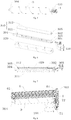
- the filter screen cleaning module 100 according to an embodiment of the present application will be described in detail below with reference to the drawings.
- a filter screen cleaning module 100 includes a cleaning box 1, a roller assembly 6, and a roller drive gear 203.
- the cleaning box 1 has a cleaning cavity 101.
- the cleaning cavity 101 has a certain accommodation space, and may accommodate a guide assembly and other functional assemblies.
- the roller assembly 6 is rollably connected between two opposite side walls of the cleaning box 1.
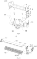
- the roller assembly 6 includes a roller inner shaft 63 and a roller outer cylinder 62, wherein the roller inner shaft 63 is fitted over the roller outer cylinder 62, a rotation limiting structure 64 is disposed between the roller outer cylinder 62 and the roller inner shaft 63, and the roller outer cylinder 62 is configured to contact with the filter screen 400 to drive the filter screen 400 to move.
- the roller inner shaft 63 serves as a rotating shaft of the roller assembly 6, and the rotating shaft is fitted over the roller outer cylinder 62 to drive the filter screen 400 to move.
- the rotation limiting structure 64 forms a limit between the roller inner shaft 63 and the roller outer cylinder 62 to prevent any circumferential displacement therebetween when the roller assembly 6 is rotated.
- the roller drive gear 203 is provided on the cleaning box 1, and is connected with the roller assembly 6.
- the roller drive gear 203 may transmit external power to the entire roller assembly 6, such that the roller assembly 6 is rollable.
- the cleaning box 1 has a cleaning cavity 101, providing the roller assembly 6 with a space for the whole roller assembly 6 to move and an efficient connection position, such that the roller assembly 6 is relatively stable when rolling, with a small position offset and the roller assembly 6 may cooperate with other components subsequently better after driving the filter screen 400 to move.
- the roller assembly 6 preliminarily rinses on the filter screen 400 to some extent, and the scattered dust may fall into the cleaning box 1.
- the roller assembly 6 is fixed on the two side walls of the cleaning box 1, and may roll stably with respect to the cleaning box 1.
- the filter screen 400 is driven to move, such that different parts of the filter screen 400 may be moved to the filter screen cleaning module 100 to be cleaned.
- the roller inner shaft 63 serves as a rotating shaft of the roller assembly 6, and the rotating shaft is fitted over the roller outer cylinder 62 to drive the filter screen 400 to move.
- the outer roller 62 of the roller supports, guides and buffers the filter screen 400 to some extent, increases a contact area of the filter screen 400 and the roller assembly 6 due to movement, and increases an acting force for driving the filter screen 400 to move.
- the arrangement of the rotation limiting structure 64 between the roller outer cylinder 62 and the roller inner shaft 63 may increase the limit therebetween effectively, avoid a circumferential displacement therebetween generated when the filter screen 400 is rotated and transmitted, also avoid an excessive friction force with the filter due to a large rotational speed, and stabilize the roller assembly 6 when rolling as a whole.
- the roller drive gear 203 is arranged separately from the roller assembly 6, which may increase the ease of assembly of the roller drive gear 203 and the roller assembly 6, reduce the occupied space inside the cleaning box 1, and increase the available cleaning space of the filter screen 400.
- a rotation limiting groove 641 is arranged on an outer peripheral wall of the roller inner shaft 63
- a rotation limiting projection 642 is arranged on an inner peripheral wall of the roller outer cylinder 62
- the rotation limiting projection 642 is inserted and fitted in the rotation limiting groove 641.
- the rotation limiting groove 641 and the rotation limiting projection 642 form a rotation limiting structure 64 which improves the assembly position fixity between the roller inner shaft 63 and the roller outer cylinder 62, and prevents the circumferential slide between the roller inner shaft 63 and the roller outer cylinder 62 to avoid the circumferential displacement.
- the rotation limiting projection 642 is arranged on the outer peripheral wall of the roller inner shaft 63, and the rotation limiting groove 641 is arranged on the roller outer cylinder 62.
- the elastic buckle is inserted into the slot to form a limit.
- an adhesion structure is adopted between the roller outer cylinder 62 and the roller inner shaft 63 to limit the rotation.
- the roller outer cylinder 62 and the roller inner shaft 63 are adhered together, and the adhesive structure here is configured as a rotation limiting structure 64.
- the rotation limiting groove 641 extends in an axial direction of the roller inner shaft 63, and is open at both axial ends of the roller inner shaft 63.
- the rotation limiting groove 641 with a certain length may further improve the cooperation stability between the rotation limiting groove 641 and the rotation limiting projection 642.
- the rotation limiting groove 641 plays a guiding role to some extent, such that the roller inner shaft 63 and the roller outer cylinder 62 are easy to assemble.
- the rotation limiting groove 641 at the end is in butt joint with the rotation limiting projection 642 firstly, and then the roller outer cylinder 62 may be fitted inwards in the extending direction of the rotation limiting groove 641.
- the outer wall of the roller inner shaft 63 is provided thereon with a plurality of rotation limiting grooves 641
- the inner wall of the roller outer cylinder 62 is provided thereon with a plurality of rotation limiting projections 642 correspondingly.
- the cooperation of the plurality of rotation limiting structures 64 greatly improves the internal rotation limiting location fit.
- the roller inner shaft 63 is formed in a hollow cylindrical shape.
- the hollow cylindrical design saves materials and makes the roller assembly 6 light in weight, which consumes less power during rotation, saves power resources, and is easily driven.
- roller inner shaft 63 may also be configured as a solid cylinder which is more durable.
- the roller assembly 6 further includes: a filter screen drive gear 61, connected at the end portion of the roller inner shaft 63, for engaging with the filter screen 400 to drive the filter screen 400 to move.
- the engaging movement is realized between the filter screen drive gear 61 and the filter screen 400, which facilitates the mutual driving therebetween.
- the filter screen 400 is moved by a distance stably in unit time during the engaging movement, without offset.
- the filter screen 400 may be moved with the filter screen drive gear 61 and the roller outer cylinder 62 to a greater extent, with better coordination, and no abnormal noise generated due to the movement misalignment.
- the filter screen 400 and the roller assembly 6 are sprayed with or immersed in the washing liquid, which is favorable for rinsing to remove dust on the surface, preventing dust from flying and increasing the degree of cleanliness.
- the number of filter screen drive gears 61 is two, and the two filter screen drive gears 61 are detachably connected at two ends of the roller inner shaft 63, which facilitates the assembly of the filter screen drive gears 61 on the roller inner shaft 63, and may improve the stability when the roller inner shaft 63 is rotated.
- the roller outer cylinder 62 has a cylindrical shape which is open at both ends. A certain space is reserved at both ends of the cylinder to facilitate installation of the filter screen drive gear 61.
- a part of the peripheral wall of the roller inner shaft 63 is recessed inwards to form the rotation limiting groove 641 (the rotation limiting groove 641 is configured as a structure fitted with the above-mentioned rotation limiting projection 642), and the portion of the inner peripheral wall of the roller inner shaft 63 forming the rotation limiting groove 641 is configured as an inner projection.
- the filter screen drive gear 61 is provided thereon with an insertion portion 611 inserted in the roller inner shaft 63, and the insertion portion is snapped on the inner projection 631.
- the insertion portion 611 is inserted in the roller inner shaft 63, such that the connection between the filter screen drive gear 61 and the roller inner shaft 63 is enhanced.
- the insertion portion 611 is provided thereon with a socket 612 in the axial direction, and the socket 612 is snapped on the inner projection 631, which prevents the insertion portion 611 from rotating relative to the roller inner shaft 63, and prevents the filter screen drive gear 61 from being idling.
- the filter screen drive gear 61 is ensured to effectively drive the roller inner shaft 63 to rotate and to avoid circumferential misalignment.
- the synchronously rotating filter screen drive gear 61, the roller inner shaft 63 and the roller outer cylinder 62 may reduce the misalignment of the filter screen 400 when driving the filter screen 400 to move.
- an outer end of the filter screen drive gear 61 protrudes to form the transmission shaft 613, and a first flat position 614 is formed on the transmission shaft 613 at one end of the filter screen drive gear 61 connected with the roller drive gear 203.
- a connecting hole fitted with the first flat position 614 is formed inside the shaft on the roller drive gear 203.
- the first flat position 614 may enhance the transmission relation between the roller drive gear 203 and the filter screen drive gear 61, preventing the roller drive gear 203 from being idling without driving the filter screen drive gear 61 to rotate.
- the roller drive gear 203 transmits the external power onto the filter screen drive gear 61 of the roller assembly 6 to drive the whole roller assembly 6 to roll.
- the feature defined with “first” and “second” may include one or more of this feature explicitly or implicitly, for distinguishing between described features, regardless of order and importance.
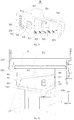
- a connecting port 108 is arranged on an upper portion of each of the two side walls of the cleaning box 1 respectively, and the transmission shaft 613 of the filter screen drive gear 61 is fitted in the connecting port 108.
- the connecting port 108 provides stable support for the rolling movement of the roller assembly 6, preventing the roller inner shaft 63 from shaking.
- the upper portion of the connecting port 108 is open to form a connecting groove 109 for conveniently mounting the roller assembly 6 into the connecting port 108 integrally.
- the filter screen drive gears 61 on both sides are mounted to two ends of the roller inner shaft 63 respectively to form an integral connection, and then the transmission shaft 613 of the filter screen drive gear 61 on one side is mounted in the connecting port 108, afterwards, the transmission shaft 613 of the filter screen drive gear 61 on the other side is mounted downwards from the connecting groove 109 into the other connecting port 108, and finally, the roller drive gear 203 is aligned with the first flat position 614 of the transmission shaft 613, to be mounted on a side of the cleaning box 1.
- the roller outer cylinder 62 as a whole is configured as a flexible member.
- the filter screen 400 may be protected effectively, so as to prevent the filter screen 400 from being scratched during transmission.
- the flexible contact and friction between the roller outer cylinder 62 and the filter screen 400 may increase the cleanliness of the filter screen 400.
- the relative movement therebetween may also realize the rinsing effect to some extent.
- the roller outer cylinder 62 has a Shore hardness of 30 to 70, ensuring smooth movement of the filter screen 400 and reducing abnormal noise during the movement.
- the roller outer cylinder 62 is provided thereon with a plurality of flexible edges 621.
- the flexible edges 621 may further enhance the rolling friction force and the degree of contact fit between the roller outer cylinder 62 and the filter screen 400.
- the flexible edges 621 extend in the axial direction of the roller assembly 6, and are disposed in one-to-one correspondence to the teeth on the filter screen drive gear 61.
- the filter screen 400 is driven by the filter screen drive gear 61 and the roller outer cylinder 62, and the rib-like protrusion 401 on the filter screen 400 is snapped in the groove between the flexible edges 621, such that the filter screen 400 is not offset in the left and right direction when rotating, and is synchronous with the roller assembly 6 when rotating.
- the flexible edges 621 are disposed in one-to-one correspondence to the teeth of the filter screen drive gear 61.
- the entire filter screen 400 may be provided thereon with the rib-like protrusion 401 in the axial direction, which is engaged with the flexible edge 621 and the filter screen drive gear 61, so as to further enhance the coordination of movement between the roller assembly 6 and the filter screen 400.
- a filter screen raceway 65 is provided below the roller assembly 6, the filter screen raceway 65 half surrounding the lower portion of the roller assembly 6 and being formed as a curved plate.
- the middle of the filter screen raceway 65 is hollowed out, with a contact gap.
- the filter screen raceway 65 may guide the movement of the filter screen 400, such that the filter screen 400 may return to a filter position in time after washed.
- the hollow design easily forms better contact between the lower portion of the roller assembly 6 and the screen brush assembly 3 as well as the filter screen 400 rotated to the lower portion and the screen brush assembly 3 to facilitate dust removal.
- the shaft hole 104 is arranged on the wall of the cleaning box 1.
- the screen brush assembly 3 is rollably connected between the two opposite box walls of the cleaning box 1, for removing impurities on the filter screen 400.
- the screen brush assembly 3 may be located in the cleaning cavity 101, or above the cleaning cavity 101.
- the end hole 301 is arranged on at least one end surface of the screen brush assembly 3.
- the screen brush drive gear 4 is located outside the cleaning box 1 to connect a power source, and is coaxially provided with the screen brush connecting shaft 410 which passes through the shaft hole 104 into the end hole 301 and is rotated synchronously with the screen brush assembly 3. Driven by the power source, the screen brush drive gear 4 is rotated, and the power is transmitted onto the screen brush connecting shaft 410 and the screen brush assembly 3 successively to provide continuous power for the rolling movement of the screen brush assembly 3.
- the screen brush connecting shaft 410 is provided thereon with an elastic buckle 411 snapped in the end hole 301.
- the elastic buckle 411 has a certain elastic deformation force, which facilitates the insertion into and detachment from the end hole 301, thereby facilitating the disassembly and assembly of the screen brush drive gear 4 and the screen brush assembly 3.
- the screen brush connecting shaft 410 is provided with a second flat position 412, and the end hole 301 is formed in a shape matching the screen brush connecting shaft 410.
- the arrangement of the second flat position 412 may increase the fitness of the screen brush connecting shaft 410 and the end hole 301, and better realize the limit to the screen brush connecting shaft 410, avoiding the situation where the screen brush connecting shaft 410 is rotated without driving the screen brush assembly 3 to rotate, which facilitates the transmission of the power and the stable rotation of the screen brush assembly 3.
- the screen brush connecting shaft 410 is provided thereon with the above-mentioned elastic buckle 411 and the second flat position 412 at the same time.
- the elastic buckle 411 is buckled up on the inner end surface of the screen brush assembly 3, such that the axial endplay of the screen brush assembly 3 when rolling is limited.
- the screen brush assembly 3 includes: a screen brush inner shaft 310 and a screen brush body 320.
- the two ends of the screen brush inner shaft 310 are connected between the two opposite side walls of the cleaning box 1, and the end hole 301 is disposed on the end surface of the screen brush inner shaft 310.
- the screen brush body 320 is disposed on the peripheral wall of the screen brush inner shaft 310, for contacting the filter screen 400.
- the screen brush body 320 directly contacts the filter screen 400, for better cleaning the filter screen 400.
- the screen brush body 320 is formed in a cylindrical shape, and the screen brush inner shaft 310 is fitted over the screen brush body 320.
- the cylindrical screen brush body 320 is easily disassembled from and assembled with the screen brush inner shaft 310 and is replaced conveniently.
- the screen brush body 320 is formed in a sheet-like shape and wrapped around the peripheral wall of the screen brush inner shaft 310 after bent, which facilitates manufacturing, makes the connection between the assembled screen brush body 320 and the screen brush inner shaft 310 closer, and avoids the offset of the screen brush body 320 on the screen brush inner shaft 310 when the screen brush assembly 3 is rolling.
- the screen brush body 320 is configured as a layer of carpet with filament fiber, and is connected with the screen brush inner shaft 310 integrally by adhesive.
- the screen brush body 320 may also be configured as a flexible cylinder with a layer of filament, and the screen brush inner shaft 310 is fitted over the flexible cylinder.
- the screen brush body 320 may also be configured as a cleaning body with smooth fine bristles on the surface.
- the screen brush inner shaft 310 includes a lower cover 311 of the inner shaft and an upper cover 312 of the inner shaft.
- the lower cover 311 of the inner shaft is formed in an elongated shape, the lower cover 311 of the inner shaft is provided thereon with a notch 302 of the inner shaft, and one end of the lower cover 311 of the inner shaft is formed with a mating shaft 304.
- the upper cover 312 of the inner shaft is formed in an elongated shape, the upper cover 312 of the inner shaft is disposed at the notch 302 of the inner shaft, and the upper cover 312 of the inner shaft is fitted with the other end of the lower cover 311 of the inner shaft to form the end hole 301.
- the screen brush connecting shaft 410 passes through the lower cover 311 of the inner shaft and is connected with the upper cover 312 of the inner shaft.
- the elongated lower cover 311 of the inner shaft and the upper cover 312 of the inner shaft are fitted integrally to support the screen brush body 320 together.
- the screen brush inner shaft 310 supports the screen brush body 320 to clean the filter screen 400, and the screen brush inner shaft 310 is subjected to a relatively large tangential force and a bending moment, it is necessary to strengthen the structural strength and rigidity of the screen brush inner shaft 310.
- the screen brush inner shaft 310 is divided into the lower cover 311 of the inner shaft and the upper cover 312 of the inner shaft which are connected with each other to improve the structural strength and rigidity of the screen brush inner shaft 310, and a reinforcing structure, such as a reinforcing rib, is processed on the lower cover 311 of the inner shaft and the upper cover 312 of the inner shaft much more easily.
- the lower cover 311 of the inner shaft and the upper cover 312 of the inner shaft which are separately designed enable the screen brush connecting shaft 410 to be snapped at a desired position more easily, thereby facilitating the reliability of the overall assembly.
- the lower cover 311 of the inner shaft and the upper cover 312 of the inner shaft are integrally formed in a detachable connection manner, such as an engagement hole, a screw, or the like.
- the lower cover 311 of the inner shaft and the upper cover 312 of the inner shaft are integrally formed by welding (such as ultrasonic welding) and gluing.
- a shaft hole 104 is arranged on each of the two opposite side walls of the cleaning box 1, the matching shaft 304 is inserted into one of the shaft holes 104, and the screen brush connecting shaft 410 is fitted and connected in the other shaft hole 104, such that the screen brush assembly 3 is stably connected on the cleaning box 1 to avoid shaking during the cleaning operation.
- an anti-rotation block 305 is arranged at each of two ends of the upper cover 312 of the inner shaft in the longitudinal direction, and the inner wall of the notch 302 of the inner shaft is provided thereon with the corresponding anti-rotation groove 303.
- the anti-rotation block 305 and the anti-rotation groove 303 are fitted to further increase the limit between the lower cover 311 of the inner shaft and the upper cover 312 of the inner shaft, such that the lower cover 311 of the inner shaft and the upper cover 312 of the inner shaft are less likely to rotate after assembled.
- the cleaning box 1 is provided thereon with a water inlet 105 and a water outlet 106.
- the washing liquid may be introduced from the water inlet 105, and the waste liquid after washing is discharged outwards from the water outlet 106.
- the water outlet 106 which is communicated with the cleaning cavity 101 is arranged at the bottom of the cleaning box 1.
- the water outlet 106 at the bottom facilitates the discharge of water in the cleaning cavity 101 under gravity.
- no water inlet 105 may be arranged on the cleaning box 1, but water is sprayed downwards directly from above the cleaning box 1 against the roller assembly 6 and the filter 200, which is also included in the protection scope of the present application.
- the cleaning cavity 101 may accommodate dripping water, and may also store a part of the water to prevent the water from splashing around during the rinsing. After the water stored in the cleaning cavity 101 reaches a certain depth, the roller assembly 6 and the filter screen 400 may be immersed in water to perform rinsing.
- the water inlet 105 is disposed toward the screen brush assembly 3, and the screen brush assembly 3 is disposed at an upper portion of the cleaning cavity 101. At this point, water may be sprayed from the water inlet 105 to the side surface of the screen brush assembly 3, so as to wet the screen brush assembly 3, clean off the dust on the screen brush assembly 3, and improve the ability of the screen brush assembly 3 to clean the filter screen 400.
- the water inlet 105 is disposed at an upper portion of the cleaning cavity 101 and water is sprayed toward the screen brush assembly 3. At this point, the water in the water inlet 105 is sprayed from the upper portion onto the screen brush assembly 3, and the clean water is first sent to the contact portion of the screen brush assembly 3 and the filter screen 400, greatly improving the ability of cleaning the filter screen 400 (filter screen 400, as shown in Fig. 4 ).
- At least a portion of the screen brush assembly 3 is immersed within the cleaning cavity 101.
- dirty water on the screen brush assembly 3 may fall in the cleaning cavity 101 accurately, without spilling.
- the screen brush assembly 3 immersed in the water may be washed again.
- the water inlet 105 is disposed toward the screen brush assembly 3, and the screen brush assembly 3 is immersed in the cleaning cavity 101.
- the screen brush assembly 3 may be washed in all directions.
- a dedusting member 5 is arranged below the screen brush assembly 3, and is provided thereon with a toothed plate which is in contact with the screen brush assembly 3.
- Comb teeth 51 are provided on the toothed plate, and both ends of the dedusting member 5 are snapped in the cleaning box 1.
- the dedusting member 5 may comb the impurities, such as hair on the cleaning box 1, into the cleaning cavity 101, thereby increasing the cleaning effect of the screen brush assembly 3.
- a fixed position is arranged on the inner wall of the cleaning cavity 101 in the cleaning box 1, and the chip filter member 8 is located below the dedusting member 5.
- the chip filter member 8 is provided thereon with a grating plate 81 for blocking the flow of impurities in the water toward the water outlet 106.
- the chip filter member 8 is provided thereon with a snap-in portion 83 snapped at a fixed position.
- the chip filter member 8 may filter impurities in the dirty water from the screen brush assembly 3, such as hair, to prevent impurities from clogging the water outlet 106.
- the snap-in portion 83 is configured as an elastic fastener, and each of the two opposite sides of the chip filter member 8 is provided with the elastic fastener.
- the inner wall of the cleaning cavity 101 is also provided with two fixed positions which cooperate with the snap-in portion 83.
- the elastic fastener is easy to mount and has a certain elastic restoring force. After the chip filter member 8 is mounted in the cleaning cavity 101, the elastic force of the elastic fastener may also support the inner wall of the cleaning box 1, effectively preventing the chip filter member 8 from shaking.
- the chip filter member 8 further includes: a top guide plate 82, disposed obliquely, connected above the grating plate 81, and contacting the inner wall of the cleaning cavity 101 on all four sides in the circumferential direction.
- the inclined top guide plate 82 may guide the dirty water after the screen brush assembly 3 is washed, such that the dirty water flows downwards along the top guide plate 82 to prevent the dirty water from splashing around in the cleaning cavity 101.
- the top guide plate 82 is provided with a water hole 84 penetrating therethrough vertically.
- the water hole 84 may introduce the dirty water from the top guide plate 82 to the grating plate 81.
- the grating plate 81 includes three sections which are connected foldably, wherein the two sections are located directly below the top guide plate 82 and form the bottom wall of the chip filter member 8, and the third section is bent upwards from the bottom wall of the chip filter member 8 to connect the top guide plate 82.
- the two sections of the grating plate 81 forming the bottom wall extend downwards in a direction towards each other, and the water outlet 106 is located below a joint of the two sections of the grating plate 81 forming the bottom wall. The water filtered by the grating plate 81 is collected to the water outlet 106 and then discharged.
- a plurality of connecting plates 86 are connected between the top guide plate 82 and the grating plate 81.
- a cutout is provided on the connecting plate 86, and the snap-in portion 83 is connected on the inner wall of the cutout.
- the connecting plate 86 enhances the structural strength of the chip filter member 8 as a whole, preventing excessive dirty water from directly passing through the side wall of the chip filter member 8.
- an abutting block 85 is arranged at the top and bottom of the chip filter member 8 respectively.
- the top abutting block 85 abuts against the dedusting member 5, and the bottom abutting block 85 abuts against the inner wall of the cleaning box 1.
- the cleaning box 1 is provided therein with a support wall 107 fitted with the two sections of the grating plate 81 at the bottom, and the bottom abutting block 85 abuts against the support wall 107.
- a cleaning motor 201 is used as the power source, the cleaning motor 201 drives the first transmission gear 71 to rotate, the first transmission gear 71 drives the second transmission gear 72 to rotate, and the second transmission gear 72 simultaneously drives the screen brush drive gear 4 and the roller drive gear 203 to rotate.
- the screen brush drive gear 4 transmits power to the screen brush assembly 3 through the screen brush connecting shaft 410, such that the screen brush assembly 3 is rotated;
- the roller drive gear 203 drives the filter screen drive gear 61 to rotate coaxially, so as to drive the roller outer cylinder 62, or the like to rotate, and the filter screen 400 is also driven by the filter screen drive gear 61 and the roller outer cylinder 62 to rotate. Therefore, in the contact surface of the filter screen 400 and the screen brush assembly 3, the tangential speeds of the filter screen 400 and the roller outer cylinder 62 are opposite, which facilitates the screen brush assembly 3 to better clean the filter screen 400.
- two cleaning motors 201 may be provided to drive the roller drive gear 203 and the screen brush drive gear 4 respectively, without other intermediate transmission gears, and no specific limitation is made herein.
- the power assembly 2 includes the above-mentioned cleaning motor 201 and roller drive gear 203.
- a gear cover 7 is disposed on the side of the cleaning box 1 to close the power assembly 2, such that each of the gears is in a relatively closed working space to prevent the interference with the gear due to foreign matter caught on the gear.
- the filter screen cleaning module 100 further includes a water inlet pipe 91, a water pump assembly 92, a water outlet control valve 93, and a drain pipe 94, wherein one end of the water inlet pipe 91 is connected with the water inlet 105, the other end of the water inlet pipe 91 is connected with the water pump assembly 92 for pumping down water from a water container and pumping up the water from the water inlet pipe 91 to the water inlet 105, the outlet control valve 93 is configured for controlling the water outlet 106 to be open or closed, the water outlet 106 is connected with the drain pipe 94, and water is discharged to a drain port of the water container through the drain pipe 94.
- the water outlet control valve 93 is connected with the drain pipe 91, and a water outlet control port of the water outlet control valve 93 is disposed dead against the drain port of the water container.
- An air processing device 1000 includes: the above-mentioned filter screen cleaning module 100, and the structure of the filter screen cleaning module 100 is not described herein.
- the air processing device 1000 with the filter screen cleaning module 100 is provided with the roller assembly 6 in the above-mentioned filter screen cleaning module 100, which may not only stably drive the filter screen 400, but also preliminarily wash the filter screen 400.
- the components work stably during the cleaning operation, no abnormal noise is easily generated, and the filter screen 400 is ensured to be guided and brought to the corresponding position for subsequent cleaning.
- the air processing device 1000 may be configured as an indoor unit of an air conditioner, or a purifier, or other devices provided with a filter and a dust filter.
- the air processing device 1000 is configured as an indoor unit of an air conditioner
- the filter screen cleaning module 100 is connected on the chassis 220 of the indoor unit of the air conditioner
- the filter screen cleaning module 100 is located above the drain pan 300 of the indoor unit of the air conditioner.
- the top of the casing 200 of the indoor unit of the air conditioner has an air inlet 210, and the filter screen 400 is movably disposed at the air inlet 210.
- the casing 200 includes a chassis for fixing a heat exchanger and a fan.
- the chassis 220 includes a back plate 221 and a bottom plate 222, wherein the back plate 221 is arranged in the vertical direction, and the bottom plate 222 is connected in front of the bottom of the back plate 221.
- a rear end of the drain pan 300 is connected with the a side of the drain pan 300 is connected with the bottom plate 222.
- the filter screen cleaning module 100 is connected with the back plate 221 and the drain pan 300 respectively.
- the water pump assembly 92 is at the bottom of the filter screen cleaning module 100.
- the water pump assembly 92 includes a base, a drain port and a suction port, wherein the suction port is disposed at the bottom of the base, and the base is flush with an inner side surface at the bottom of the drain pan 300, which ensures that the water pump assembly 92 may suck water at a lower level in the drain pan 300.
- the drain port is connected with the water inlet pipe 91.
- the bottom of the drain pipe 94 is aligned with the drain port on the drain pan 300 for draining water.
- the "synchronization" of two moving members means that the two moving members have a certain relative relationship in unit time, the relative change in displacement, or in speed, or in frequency being consistent. More specifically, the "synchronous rotation" of the coaxial rotating members means that the moving direction, the rotational angular velocity, and the time of starting and stopping the rotation of the two moving members are the same.
- a filter screen cleaning module 100 includes: a cleaning box 1, a power assembly 2, a screen brush assembly 3, a screen brush drive gear 4, a dedusting member 5, a roller assembly 6, a gear cover 7, a chip filter member 8, an water inlet pipe 91, a water pump assembly 92, a water outlet control valve 93, and a drain pipe 94.
- the cleaning box 1 has a cleaning cavity 101 with an open upper end.
- the box wall of the cleaning box 1 is provided with a shaft hole 104.
- a water inlet 105 is arranged at the position of the upper portion of the cleaning box 1 higher than the shaft hole 104.
- a support wall 107 is arranged at the lower end of the cleaning box 1, and is provided thereon with a downward water outlet 106.
- a connecting port 108 is arranged on each of two opposite side walls at the upper portion of the cleaning box 1.
- the roller assembly 6 is rollably connected between the two connecting ports 108.
- the roller assembly 6 includes the filter screen drive gear 61, the roller outer cylinder 62 and the roller inner shaft 63, wherein each of the end portions of the roller inner shaft 63 is connected with one filter screen drive gear 61, the roller inner shaft 63 is fitted over the roller outer cylinder 62, the outer peripheral wall of the roller inner shaft 63 is provided thereon with the rotation limiting groove 641, the inner peripheral wall of the cylindrical roller outer cylinder 62 is provided thereon with the rotation limiting projection 642, and the rotation limiting projection 642 is inserted and fitted in the rotation limiting groove 641.
- the outer end of the filter screen drive gear 61 protrudes to form the transmission shaft 613 extending into the connecting port 108, and one of the transmission shafts 613 is formed thereon with an axial first flat position 614 which is fitted and connected with the roller drive gear 203.
- the filter screen drive gear 61 is configured for being engaged with the filter screen 400 to drive the filter screen 400 to move
- the roller outer cylinder 62 is configured for flexibly contacting with the filter screen 400 to drive the filter screen 400 to move for cleaning.
- the bottom of the filter screen 400 is provided with a rib-like protrusion 401 which cooperates with the filter screen drive gear 61 and the roller outer cylinder 62.
- the filter screen raceway 65 is provided below the roller assembly 6, half surrounding the lower portion of the roller assembly 6.
- the screen brush assembly 3 is rollably connected between two opposite side walls of the cleaning box 1, for removing impurities on the filter screen 400.
- the screen brush assembly 3 includes: the screen brush inner shaft 310 and the screen brush body 320.
- the screen brush body 320 is disposed on the peripheral wall of the screen brush inner shaft 310, and the screen brush body 320 is configured to contact and clean the filter screen 400.
- the screen brush inner shaft 310 includes the lower cover 311 of the inner shaft and the upper cover 312 of the inner shaft, which are snapped integrally and connected by screws.
- One end of the lower cover 311 of the inner shaft is formed with the mating shaft 304, the other end of the lower cover 311 of the inner shaft is fitted with the upper cover 312 of the inner shaft to form an end hole 301, and the mating shaft 304 is inserted into one shaft hole 104.
- the screen brush drive gear 4 is located outside the cleaning box 1 to connect the power source, and is coaxially provided thereon with the screen brush connecting shaft 410.
- the screen brush connecting shaft 410 passes through another shaft hole 104, extends into the end hole 301 and rotates in synchronization with the screen brush assembly 3.
- a dedusting member 5 is arranged below the screen brush assembly 3, and is provided thereon with a toothed plate which is in contact with the screen brush assembly 3.
- Comb teeth 51 are provided on the toothed plate, and both ends of the dedusting member 5 are snapped in the cleaning box 1.
- a fixed position is arranged on the inner wall of the cleaning cavity 101 in the cleaning box 1, and the chip filter member 8 is located below the dedusting member 5.
- the chip filter member 8 is provided thereon with a grating plate 81 for blocking the flow of impurities in the water toward the water outlet 106.
- the chip filter member 8 is provided thereon with a snap-in portion 83 snapped at a fixed position. The lowest portion of the chip filter member 8 is aligned with the water outlet 106.
- the top abutting block 85 abutting against the dedusting member 5 is arranged on the upper portion of the chip filter member 8, and the bottom abutting block 85 abutting against the support wall 107 is arranged on the lower portion of the chip filter member 8.
- the power assembly 2 includes the cleaning motor 201, the roller drive gear 203, and the first and second transmission gears 71 and 72 for drive transmission, wherein the cleaning motor 201 drives the first transmission gear 71 to rotate, the first transmission gear 71 drives the second transmission gear 72 to rotate, and the second transmission gear 72 simultaneously drives the screen brush drive gear 4 and the roller drive gear 203 to rotate.
- the gear cover 7 is disposed at the side of the cleaning box 1 to enclose the power assembly 2 in a space.
- one end of the water inlet pipe 91 is connected with the water inlet 105, and the other end of the water inlet pipe 91 is connected with the water pump assembly 92.
- the water pump assembly 92 is configured for pumping down water from the water container and pumping up water from the water inlet pipe 91 to the water inlet 105.
- the water outlet control valve 93 is configured for controlling the water outlet 106 to be open or closed, and the water outlet 106 is connected with the drain pipe 94, and water is discharged to a drain port of the water container through the drain pipe 94.
- the indoor unit of the air conditioner is taken as an example.
- the indoor unit of the air conditioner includes a casing 200, at the top of which, an air inlet 210 is arranged.
- a movable filter screen 400 is arranged at the air inlet 210.
- the casing 200 further includes the chassis 220 consisting of the back plate 221 and the bottom plate 222, wherein the back plate 221 is arranged in the vertical direction, and the bottom plate 222 is connected in front of the bottom of the back plate 221.
- a rear end of the drain pan 300 is connected with the back plate 221, and a side of the drain pan 300 is connected with the bottom plate 222.
- the filter screen cleaning module 100 is connected with the back plate 221 and the drain pan 300 respectively, and the roller assembly 6 at the top of the filter screen cleaning module 100 is aligned with the filter screen 400.
- the power assembly 2 drives the roller drive gear 203 and the screen brush drive gear 4 to rotate
- the roller drive gear 203 drives the roller assembly 6 to rotate
- the screen brush drive gear 4 drives the screen brush assembly 3 to rotate
- the filter screen 400 follows the roller assembly 6 to rotate and forms a rotational contact surface with the rotating filter assembly 3.
- the filter screen 400 is rotated on the surface of the roller assembly 6 and is driven in the filter screen raceway 65.
- the screen brush assembly 3 brushes the dust on the filter screen 400 to its surface, and during the rotation, the dust and hair on the surface are scraped off by the dedusting member 5.
- the water pump assembly 92 pumps down water from the drain pan 300, and pumps up water from the water inlet pipe 91 into the water inlet 105, such that the surface of the screen brush assembly 3 is wet and rinsed.
- the dirty water after washing carries the impurities and hair in the dedusting member 5 to the chip filter member 8, the hair is retained on the chip filter member 8, and the dirty water is discharged from the water outlet 106 to the drain pipe 94 which is aligned with the drain port of the drain pan 300, outside the air conditioner.
- the cleaning motor 101 in the power assembly 2 is reversed to move the filter screen 400 in the direction opposite to the washing direction.
- an embodiment and “an example” means that a particular feature, structure, material, or characteristic described in connection with the embodiment or example is included in at least one embodiment or example of the present application.
- the schematic expressions to the above-mentioned terms are not necessarily referring to the same embodiment or example.
- the described particular features, structures, materials, or characteristics may be combined in any suitable manner in one or more embodiments or examples.
Landscapes
- Engineering & Computer Science (AREA)
- Chemical & Material Sciences (AREA)
- Combustion & Propulsion (AREA)
- Mechanical Engineering (AREA)
- General Engineering & Computer Science (AREA)
- Air Filters, Heat-Exchange Apparatuses, And Housings Of Air-Conditioning Units (AREA)
- Filtering Of Dispersed Particles In Gases (AREA)
- Filtration Of Liquid (AREA)
Applications Claiming Priority (3)
| Application Number | Priority Date | Filing Date | Title |
|---|---|---|---|
| CN201822009167.0U CN209181120U (zh) | 2018-11-30 | 2018-11-30 | 滤网水洗模块及空气处理装置 |
| CN201822007298.5U CN209181119U (zh) | 2018-11-30 | 2018-11-30 | 滤网清洁模块及空气处理装置 |
| PCT/CN2019/113329 WO2020108190A1 (zh) | 2018-11-30 | 2019-10-25 | 滤网清洁模块及空气处理装置 |
Publications (2)
| Publication Number | Publication Date |
|---|---|
| EP3686499A1 true EP3686499A1 (de) | 2020-07-29 |
| EP3686499A4 EP3686499A4 (de) | 2021-03-17 |
Family
ID=70854351
Family Applications (1)
| Application Number | Title | Priority Date | Filing Date |
|---|---|---|---|
| EP19798513.8A Pending EP3686499A4 (de) | 2018-11-30 | 2019-10-25 | Filtersiebreinigungsmodul und luftbehandlungsvorrichtung |
Country Status (3)
| Country | Link |
|---|---|
| EP (1) | EP3686499A4 (de) |
| JP (1) | JP6992092B2 (de) |
| WO (1) | WO2020108190A1 (de) |
Cited By (1)
| Publication number | Priority date | Publication date | Assignee | Title |
|---|---|---|---|---|
| CN113422937A (zh) * | 2021-08-23 | 2021-09-21 | 山东寿光第一建筑有限公司 | 一种基于光电控制的建筑工地安全监测预警装置 |
Families Citing this family (8)
| Publication number | Priority date | Publication date | Assignee | Title |
|---|---|---|---|---|
| CN113944958B (zh) * | 2020-07-16 | 2023-06-16 | 海信空调有限公司 | 一种室内空调器及其使用方法 |
| CN112156577B (zh) * | 2020-10-26 | 2024-09-06 | 广东三技克朗茨机械科技有限公司 | 一种烘箱除尘装置 |
| CN115127154A (zh) * | 2021-03-19 | 2022-09-30 | 广州联动万物科技有限公司 | 一种空调滤网组件和空调器 |
| CN115717732B (zh) * | 2021-08-25 | 2026-01-23 | 宁波奥克斯电气有限公司 | 新风模块和空调器 |
| CN113974480B (zh) * | 2021-10-27 | 2022-08-05 | 江苏金銮纺织科技股份有限公司 | 一种用于纺织的棉花细屑回收装置 |
| CN114963337B (zh) * | 2022-04-11 | 2025-09-30 | 珠海格力电器股份有限公司 | 除尘装置以及空调器 |
| CN115350994A (zh) * | 2022-09-05 | 2022-11-18 | 昆明理工大学 | 一种用于淫羊藿药材清洗设备 |
| CN118807388A (zh) * | 2024-07-24 | 2024-10-22 | 湖北二零九工程有限公司 | 一种大气治理用环保治污设备 |
Family Cites Families (20)
| Publication number | Priority date | Publication date | Assignee | Title |
|---|---|---|---|---|
| CN101290151B (zh) * | 2007-04-18 | 2010-05-26 | 海尔集团公司 | 空调过滤网自清洁装置 |
| JP2012154589A (ja) * | 2011-01-27 | 2012-08-16 | Mitsubishi Heavy Ind Ltd | 空気調和機 |
| KR102199380B1 (ko) * | 2014-01-17 | 2021-01-06 | 엘지전자 주식회사 | 공기조화기 |
| GB201412453D0 (en) * | 2014-07-14 | 2014-08-27 | Payne Robert A | An air conditioning filter cleaner and associated multiple filter cleaning system |
| CN105937789B (zh) * | 2016-05-06 | 2019-01-29 | 广东美的制冷设备有限公司 | 空调器及其清洁控制方法 |
| CN105953325A (zh) * | 2016-05-06 | 2016-09-21 | 广东美的制冷设备有限公司 | 空调器及其清洁控制方法 |
| CN106839123B (zh) * | 2017-03-28 | 2022-08-12 | 美的集团武汉制冷设备有限公司 | 除尘装置和挂壁式空调器 |
| CN206730731U (zh) * | 2017-03-28 | 2017-12-12 | 美的集团武汉制冷设备有限公司 | 除尘装置和挂壁式空调器 |
| CN207137575U (zh) | 2017-07-21 | 2018-03-27 | 广东美的制冷设备有限公司 | 空调过滤网的除尘装置及空调室内机 |
| CN206959172U (zh) | 2017-07-21 | 2018-02-02 | 广东美的制冷设备有限公司 | 空调室内机及有其的空调器 |
| CN208936301U (zh) * | 2018-09-20 | 2019-06-04 | 广东美的制冷设备有限公司 | 空调室内机和空调器 |
| CN208936323U (zh) * | 2018-09-30 | 2019-06-04 | 广东美的制冷设备有限公司 | 水洗模块和空调器室内机 |
| CN109185987A (zh) * | 2018-09-30 | 2019-01-11 | 广东美的制冷设备有限公司 | 水洗模块和空调器室内机 |
| CN209181120U (zh) * | 2018-11-30 | 2019-07-30 | 广东美的制冷设备有限公司 | 滤网水洗模块及空气处理装置 |
| CN209181243U (zh) * | 2018-11-30 | 2019-07-30 | 广东美的制冷设备有限公司 | 滤网水洗模块和具有其的空气调节装置 |
| CN209181122U (zh) * | 2018-11-30 | 2019-07-30 | 广东美的制冷设备有限公司 | 室内机 |
| CN209173592U (zh) | 2018-11-30 | 2019-07-30 | 广东美的制冷设备有限公司 | 滤网清洁模块及空气处理装置 |
| CN209181119U (zh) * | 2018-11-30 | 2019-07-30 | 广东美的制冷设备有限公司 | 滤网清洁模块及空气处理装置 |
| CN209173593U (zh) * | 2018-11-30 | 2019-07-30 | 广东美的制冷设备有限公司 | 滤网清洁模块及空气处理装置 |
| CN209181121U (zh) * | 2018-11-30 | 2019-07-30 | 广东美的制冷设备有限公司 | 滤网水洗模块及空气处理装置 |
-
2019
- 2019-10-25 EP EP19798513.8A patent/EP3686499A4/de active Pending
- 2019-10-25 WO PCT/CN2019/113329 patent/WO2020108190A1/zh not_active Ceased
- 2019-10-25 JP JP2019563124A patent/JP6992092B2/ja active Active
Cited By (1)
| Publication number | Priority date | Publication date | Assignee | Title |
|---|---|---|---|---|
| CN113422937A (zh) * | 2021-08-23 | 2021-09-21 | 山东寿光第一建筑有限公司 | 一种基于光电控制的建筑工地安全监测预警装置 |
Also Published As
| Publication number | Publication date |
|---|---|
| EP3686499A4 (de) | 2021-03-17 |
| JP2021511473A (ja) | 2021-05-06 |
| JP6992092B2 (ja) | 2022-01-13 |
| WO2020108190A1 (zh) | 2020-06-04 |
Similar Documents
| Publication | Publication Date | Title |
|---|---|---|
| EP3685903B1 (de) | Filtersiebreinigungsmodul und luftbehandlungsvorrichtung | |
| EP3686499A1 (de) | Filtersiebreinigungsmodul und luftbehandlungsvorrichtung | |
| JP7097811B2 (ja) | クリーニング機構、クリーニング装置、及びエア・コンディショナー | |
| CN209181119U (zh) | 滤网清洁模块及空气处理装置 | |
| EP4238471A1 (de) | Bodenbürstenanordnung und reinigungsausrüstung dafür | |
| CN210399045U (zh) | 一种具有自清洁功能的吸油烟机 | |
| JP2019152417A (ja) | 空気調和機のフィルタ清掃装置 | |
| JP4609561B2 (ja) | フィルタ清掃ユニット及び空気調和機 | |
| JPWO2004081461A1 (ja) | エアフィルタの自動清掃機能付き室内ユニットを備えた空気調和機 | |
| CN209181120U (zh) | 滤网水洗模块及空气处理装置 | |
| CN209181121U (zh) | 滤网水洗模块及空气处理装置 | |
| CN212029673U (zh) | 一种用于厨房烟囱的自动清洗烟管 | |
| JP2019152416A (ja) | 空気調和機のフィルタ清掃装置 | |
| TWI344531B (en) | Air conditioner with indoor unit having automatic filter cleaning function | |
| CN209173593U (zh) | 滤网清洁模块及空气处理装置 | |
| KR101244262B1 (ko) | 원형 브러쉬를 구비한 청소기용 헤드 | |
| CN213016851U (zh) | 贯流风机和空调室内机 | |
| JP4645059B2 (ja) | フィルター装置及び空気調和機 | |
| CN209181243U (zh) | 滤网水洗模块和具有其的空气调节装置 | |
| CN114869184A (zh) | 表面清洁头以及表面清洁装置 | |
| CN222237591U (zh) | 清洁模组、清洁设备及清洁系统 | |
| JP5631810B2 (ja) | フィルタ清掃ユニット及び空気調和機 | |
| CN220477555U (zh) | 地刷装置、清洁设备及清洁系统 | |
| CN213019941U (zh) | 贯流风机和空调室内机 | |
| KR101321145B1 (ko) | 원형 브러쉬를 구비한 청소기용 헤드 |
Legal Events
| Date | Code | Title | Description |
|---|---|---|---|
| STAA | Information on the status of an ep patent application or granted ep patent |
Free format text: STATUS: UNKNOWN |
|
| STAA | Information on the status of an ep patent application or granted ep patent |
Free format text: STATUS: THE INTERNATIONAL PUBLICATION HAS BEEN MADE |
|
| PUAI | Public reference made under article 153(3) epc to a published international application that has entered the european phase |
Free format text: ORIGINAL CODE: 0009012 |
|
| STAA | Information on the status of an ep patent application or granted ep patent |
Free format text: STATUS: REQUEST FOR EXAMINATION WAS MADE |
|
| 17P | Request for examination filed |
Effective date: 20191115 |
|
| AK | Designated contracting states |
Kind code of ref document: A1 Designated state(s): AL AT BE BG CH CY CZ DE DK EE ES FI FR GB GR HR HU IE IS IT LI LT LU LV MC MK MT NL NO PL PT RO RS SE SI SK SM TR |
|
| AX | Request for extension of the european patent |
Extension state: BA ME |
|
| RIN1 | Information on inventor provided before grant (corrected) |
Inventor name: LIU, QIWEI Inventor name: PENG, JIELIN |
|
| A4 | Supplementary search report drawn up and despatched |
Effective date: 20210216 |
|
| RIC1 | Information provided on ipc code assigned before grant |
Ipc: F24F 8/90 20210101ALI20210210BHEP Ipc: F24F 1/0073 20190101AFI20210210BHEP |
|
| DAV | Request for validation of the european patent (deleted) | ||
| DAX | Request for extension of the european patent (deleted) | ||
| STAA | Information on the status of an ep patent application or granted ep patent |
Free format text: STATUS: EXAMINATION IS IN PROGRESS |
|
| 17Q | First examination report despatched |
Effective date: 20230728 |