EP2954815A1 - Aspirateur doté d'un filtre amovible et filtre pouvant être utilisé dans un tel aspirateur - Google Patents
Aspirateur doté d'un filtre amovible et filtre pouvant être utilisé dans un tel aspirateur Download PDFInfo
- Publication number
- EP2954815A1 EP2954815A1 EP15001547.7A EP15001547A EP2954815A1 EP 2954815 A1 EP2954815 A1 EP 2954815A1 EP 15001547 A EP15001547 A EP 15001547A EP 2954815 A1 EP2954815 A1 EP 2954815A1
- Authority
- EP
- European Patent Office
- Prior art keywords
- filter
- vacuum cleaner
- handle
- holding element
- receptacle
- Prior art date
- Legal status (The legal status is an assumption and is not a legal conclusion. Google has not performed a legal analysis and makes no representation as to the accuracy of the status listed.)
- Granted
Links
Images




Classifications
-
- A—HUMAN NECESSITIES
- A47—FURNITURE; DOMESTIC ARTICLES OR APPLIANCES; COFFEE MILLS; SPICE MILLS; SUCTION CLEANERS IN GENERAL
- A47L—DOMESTIC WASHING OR CLEANING; SUCTION CLEANERS IN GENERAL
- A47L9/00—Details or accessories of suction cleaners, e.g. mechanical means for controlling the suction or for effecting pulsating action; Storing devices specially adapted to suction cleaners or parts thereof; Carrying-vehicles specially adapted for suction cleaners
- A47L9/10—Filters; Dust separators; Dust removal; Automatic exchange of filters
- A47L9/12—Dry filters
Definitions
- the invention relates to a vacuum cleaner with a removable from the vacuum cleaner filter.
- the invention further relates to a filter which can be used in such a vacuum cleaner.
- Vacuum cleaners with a removable from the vacuum cleaner filter are known per se.
- the filter described below for example - but not exclusively - as a pre-filter in a vacuum cleaner with a central filter and an upstream cyclone separator into consideration.
- a pre-filter between the cyclone separator and the central filter is necessary to protect the central filter from damage or soiling, for example with fibers or the like. This is usually achieved by means of a prefilter with a filter medium in the form of plastic fabric or the like.
- the pre-filter can be easily cleaned by a user of the vacuum cleaner.
- a prerequisite for this in turn is that the pre-filter is easily accessible and can be easily removed from the vacuum cleaner and, after cleaning, can also be used on the vacuum cleaner with the same ease.
- a filter prefilter in the vacuum cleaner and to remove the filter on the vacuum cleaner to make an amount.
- the filter for removal from the vacuum cleaner or from the filter holder comprises a handle pivotable about a pivot axis that the handle at least one comprises holding member extending beyond the pivot axis and moving with the handle and that the vacuum cleaner has at least one holding element receptacle for receiving the holding element on the filter receptacle intended for receiving the filter when the filter is or is inserted into the filter receptacle.
- the solution proposed here is characterized by the pivotable handle, by means of which the filter is removed from the outside separately from the filter holder by the user of the vacuum cleaner uses the handle. Also in the further handling the filter and especially when cleaning the filter, the filter is held only on the handle, so that the user of the vacuum cleaner does not come into contact with the deposited on the filter dirt.
- this or these comprises a hook-shaped holding element which engages with a pivoting of the handle into the holding element holder and behind a holding element receiving front piece.
- the hook shape also allows a fixation of the filter in the filter holder against a force that is required for deforming a seal intended for sealing the filter in the filter holder.
- For a rear part of the Garelementingfront Griffs is formed so that there can attack the hook-shaped retaining element.
- One way in this regard is to raise a nose on the back of the retainer receiving front piece. Behind this, a nose of the holding element, which gives the holding element whose hook shape grab.
- a length of a holding element web of the holding element measured from the swivel axis of the handle is dimensioned so that a lifting of the filter from the filter receptacle can be effected by means of a swiveling / unfolding of the handle by a front end of the holding element web an inner surface of the holding element receptacle presses.
- This facilitates the removal of the filter from the filter holder.
- Parts of the filter are in the "Dirt area" of the vacuum cleaner, so that it can happen that the filter in the filter holder is something tight. A gasket between the filter and the filter holder increases this seizure if necessary.
- a length of Garelementingfront ceremoniess and a length of Garelementstegs are dimensioned so that a vacuum removed from the filter with a pivoted / folded handle is not completely inserted into the filter holder, because the Garelementsteg front of the Garelementingfront founded stops and prevents further insertion of the filter in the filter holder. In this way, an unachieved fixation of the filter in the filter holder is immediately noticed and by re-swinging the handle and correct insertion of the filter into the filter holder, the correct fixation of the filter can be done in the filter holder.
- a depth of the holding element holder and a height of a nose located at the free end of the holding element web are matched to one another that with the pivoting of the handle and thus causing fixation of the filter in the filter holder pressing the filter can be effected in a seal located between the filter and filter receptacle in the area of the filter receptacle.
- the handle and the holding element act as Kraftarm or load arm of a lever and by means of the compared to the load arm (holding element) significantly longer power arm (handle) are a secure fit of the filter in the filter holder and a all-round secure contacting a seal between the filter and Filter intake reached.
- the handle in one embodiment of the device or the vacuum cleaner comprises locking or detent means which are intended to cooperate with at least one corresponding locking or locking means on a pivot axis bearing element, at least one preferred position (detent position) for a position of the handle on the filter can be defined in which the handle engages for easy handling of the filter.
- the handle by means of a housing part of the vacuum cleaner is actuated.
- the relevant housing part is opened to access the filter, for example pivoted.
- the handle When closing the vacuum cleaner, the housing part meets the handle, unless it has been folded in the filter holder when fixing the filter.
- the handle bevelled and / or chamfered this can also by means of the housing part, so to speak automatically, fold when closing the vacuum cleaner. This collapse of the handle causes the above-described and subsequently explained further fixation of the filter in the filter holder.
- the invention presented here is thus also a filter with means for use in a vacuum cleaner of the type described here and below, that is to say in particular a handle and a holding element movable with the handle as such means.
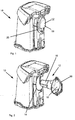
- FIG. 1 and FIG. 2 show a part of a generally known per se vacuum cleaner 10, whose interior - in principle also known per se - acts as a cyclone separator.
- the vacuum cleaner 10 comprises before a suction fan, not shown here, a likewise not shown central filter.
- a filter 12 acting as a prefilter is provided.
- FIG. 1 shows a configuration with filter 12 inserted. When displayed in FIG. 2 the filter 12 is removed from the vacuum cleaner 10. In this case, on the vacuum cleaner 10 for receiving the filter 12 specific filter receptacle 14 can be seen.
- the filter 12 comprises a plastic fabric 16 acting as a filter medium or the like, which projects into the interior of the vacuum cleaner 10 as a dip tube due to its cylindrical or conical shape in the case of a filter 12 inserted in the filter holder 14.
- the filter 12 includes following the dip tube a - bent here - part of an exhaust duct 18 and through the exhaust duct 18 flowing, pre-filtered by the filter medium suction air passes due to the negative pressure generated by the suction fan to the central filter.
- the filter 12 comprises a pivotable about a pivot axis handle 20.
- FIG. 3 shows the filter 12 alone with a top view of acting as a filter medium plastic fabric 16 (dip tube).
- the immersion tube part of the filter 12 opposite handle 20 is only partially visible.
- the handle 20 comprises at least one holding element 22 extending beyond the pivot axis of the handle 20. Shown is an embodiment with two holding elements 22. On this basis, but without waiving any further generality, the further description will be continued.
- the pivot axis of the handle 20 is indicated by the two vertical arrows.
- the two holding elements 22 are integrally formed on the handle 20 or permanently connected in an otherwise suitable manner with the handle 20 and are therefore moved during pivoting of the handle 20.
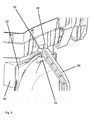
- FIG. 4 is an enlarged section of the illustration in FIG. 1 ,
- the filter 12 is inserted into the filter receptacle 14 and fixed there and the handle 20 is located in a position referred to below as pivoted or folded.
- the filter 12 on its outwardly facing surface on two pivot axis bearing elements 24.
- the two retaining elements 22 are at the in FIG. 4 shown configuration for fixing the filter 12 in the filter holder 14 effectively. Therefore, only one holding element 22 and this only partially visible.
- Each holding element 22 engages for fixing the filter 12 in the filter holder 14 in a holding element holder 26 of the vacuum cleaner 10 at the edge of the filter holder 14 a.
- FIG. 5 shows in a comparison to FIG. 4 enlarged shape a situation when inserting the filter 12 in the filter receptacle 14 or when removing the filter 12 from the filter receptacle 14.
- the position shown and necessary for the handle 20 is hereinafter referred to as swung or unfolded. Visible are the upper holding element 22 located at the end of the handle 20 and the upper holding element receptacle 26.
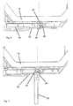
- FIG. 6 shows a situation with fixed filter 12 and corresponding pivoted handle 20.
- FIG. 7 shows a situation as it results either when inserting the filter 12 into the filter holder 14 or when removing the filter 12 from the filter holder 14.
- the handle 20 is swung out for it.
- FIG. 8 is an enlarged section of the illustration in FIG. 6 .
- the holding element 22 is shaped like a hook and comprises a holding element web 28 and a nose 30 at the free end of the holding element web 28.
- the holding element receptacle 26 is also characterized in the embodiment shown by a hook-like shape and comprises a Garelementingfront Skype 32 and a Nose 34 at the free end of Garelementingfront forums 32. These terms will be used in the following, even if their reference numerals in the interest of clarity of the other representations there are not repeated in every case.
- a pivoted-in handle 20 engages the holding member 22 in the holding element holder 26, namely with the holding element web 28 behind the Halteelementinformationfront Huawei 32.
- the handle 20 When inserting the filter 12 in the filter holder 14, the handle 20 is initially in the pivoted position ( FIG. 7 ) and, when the filter 12 is fully positioned in front of the filter receptacle 14, folded in the pivoted position.
- the holding element 22 engages in accordance with the respective pivot position of the Handle 20 gradually into the holding element holder 26 a.
- handle 20 results in the FIG. 6 shown situation.
- the nose 30 at the end of the holding element web 28 comes - different than in FIG.
- FIG. 6 - contacts the inner surface of the retainer receiving front 32 and causes the filter 12 to be pressed into a seal, not shown.
- a depth of the holding element receptacle 26 and a height of the nose 30 are coordinated so that with the pivoting of the handle 20 and thus causing fixation of the filter 12 in the filter receptacle 14, the press-fitting results in the seal.
- the seal can be located either on the filter 12 or in the filter receptacle 14.
- the two lugs 30, 34 cause the retaining element 22 to hook onto the holding element receiving front piece 32 and allow the filter 12 to be drawn into the filter holder 14 and the seal during pivoting of the handle 20, as it were.
- the illustrations in FIG. 6 and FIG. 7 are representations of the circumstances without such a seal, so that the in FIG. 6 apparent distance between the nose 30 and the inner surface of the Garelementabilityfront Griffs 32 results.
- the edge of the front end of the holding element web 28 coming into contact with the holding element receiving inner surface 36 is chamfered or rounded off.
- the aforesaid depth of the holding element receptacle 26 is the distance between the holding element receiving inner surface 36 and the surface of the holding element receiving front piece 32 facing the interior of the holding element receptacle 26.
- FIG. 7 shows the situation with a pivoted handle 20 and a voltage applied to the holding element receiving inner surface 36 front end of the Garelementstegs 28.
- filter 12 can be seen that in the situation in FIG. 7 the filter 12 is already lifted by a small distance from the filter holder 14.
- the handle 20 Upon complete removal of the filter 12 from the filter holder 14 and during further handling of the filter 12, the handle 20 remains in the swung-out position, ie in a direction perpendicular to the front surface of the filter 12 or at least substantially vertical position.
- the device proposed here for fixing the filter 12 in the filter receptacle 14 and for removing the filter 12 from the filter receptacle 14 is designed so that the filter 12 can only be completely inserted into the filter receptacle 14 when the handle 20 is initially in the deployed position when inserting the filter 12. If the handle 20 is folded over too early, ie before the holding element 22 engages in the holding element holder 26, the holding element web 28 abuts the outside of the holding element receiving front piece 32 when trying to insert the filter 12 into the filter holder 14. This introduces another insertion the filter 12 is prevented in the filter holder 14.
- the vacuum cleaner 10 is preferably constructed so that it can not close with a not completely inserted into the filter holder 14 filter 12 and in a particular embodiment of such a vacuum cleaner 10 can not start at a not fully closed vacuum cleaner 10, the suction fan. In this way it is effectively prevented that the vacuum cleaner 10 is taken with a not completely inserted into the filter holder 14 filter 12 in operation.
- the described abutment of the holding element web 28 on the outside of Garelementabilityfront matterss 32 is made possible by the lengths of the two parts of the device for fixing the filter 12 in the filter holder 14 and for removing the filter 12 are selected from the filter holder 14 and suitably matched.
- the length of the Garelementabilityfront matterss 32 and the length of the holding element web 28 are dimensioned so that a 10 removed from the vacuum cleaner filter 12 with a pivoted handle 20 is not completely inserted into the filter holder 14, because then the holding element web 28 abuts the outside of the Garelementabilityfront mixes 32 and prevents further insertion of the filter 12 into the filter receptacle 14.
- the handle 20 comprises locking or locking means 38, which cooperate with at least one corresponding locking or locking means 40 are determined on the pivot axis bearing element 24.
- these locking or locking means 38, 40 for example, in the form of at least one notch 40 on the side of the pivot axis bearing element 24 and a form-fitting cut to a width and a depth of the notch 40 survey 38 on the handle 20 executed.
- FIG. 9 shows an enlarged detail of the illustration in FIG. 4 ,
- the handle 20 is pivoted in and on the pivot axis bearing element 24 is particularly well that notch 40 can be seen, by means of which the handle 20 is releasably fixed in the swung-out state.
- the representation in FIG. 10 shows the contrast, the situation with swung handle 20.
- the survey 38 on the handle is in the previously in the description of FIG. 9 mentioned notch 40 engaged.
- In the circumferential direction of the pivot axis bearing element 24 about 90 ° before this notch 40 is another notch 40, in which the survey 38 at the in FIG. 9 locked situation shown engaged.
- the device for fixing the filter 12 in the filter receptacle 14 and for removing the filter 12 from the filter receptacle 14 is specifically based on the illustrations in FIG FIG. 2 and FIG. 5 the tapered shape of the handle 20 recognizable.
- the beveled shape results from the fact that the handle 20, starting from the pivot axis bearing elements 24 each comprises two diagonal sections, which meet at a straight central portion of the handle 20. If the filter 12 is already inserted into the filter holder 14, without the handle 20 is pivoted, this tapered shape of the handle 20 causes when closing the vacuum cleaner 20, the housing part in question strikes the tapered portion of the handle 20 and this to the Page presses. This Zur-side-pressing causes a pivoting of the handle 20, until finally the in FIG.
- the tapered shape of the handle 20 thus effectively causes an automatic fixation of the filter 12 in the filter holder 14, if the user of the vacuum cleaner 10 has not made this when closing the vacuum cleaner 10 itself.
- the possibility that the relevant housing part of the vacuum cleaner 10 pushes the handle 20 to the side and thus causes the fixation of the filter 12 in the filter holder 14 can be further supported by the fact that in the illustration in FIG. 4 right outer edge of the handle 20 is rounded or chamfered and / or that the relevant housing part of the vacuum cleaner 10 has a guide contour which causes the pivoting of the handle 20.
- the weight of the respective housing part of the vacuum cleaner 10 is usually sufficient to move the elevation 38 out of the detent position in the notch 40 and then to swivel the handle 20 with a sufficient force, so that the holding element 22 engages in the holding element holder 26 and the filter 12 is fixed in the filter holder 14.
- a vacuum cleaner 10 is indicated with a filter 12 which can be removed from the vacuum cleaner 10, wherein the filter 12 for removal from the vacuum cleaner 10 comprises a handle 20 pivotable about a pivot axis, wherein the handle 20 comprises at least one extending beyond the pivot axis and with the handle 20 moved holding member 22 and wherein the vacuum cleaner 10 has a filter receptacle 14 for receiving the filter 12 and the filter receptacle 14 at least one holding element receptacle 26 for receiving the holding member 22, when the filter 12 is inserted into the filter receptacle 14 or is.
- the removal of the filter 12 on the vacuum cleaner 10 and from the filter holder 14 is carried out exclusively by means of the handle 20, so that the removal of the filter 12 for the user of the vacuum cleaner 10 can be accomplished in a very hygienic manner, because the user with neither on Filter 12 attached dust comes into contact, still has to access the filter 12 in a dirt area of the vacuum cleaner 10 must.
- the handle 20 By means of the handle 20, the filter 12 is also fixed after cleaning in a simple and intuitively detectable manner in the filter holder 14 again.
Landscapes
- Engineering & Computer Science (AREA)
- Mechanical Engineering (AREA)
- Filters For Electric Vacuum Cleaners (AREA)
Applications Claiming Priority (1)
| Application Number | Priority Date | Filing Date | Title |
|---|---|---|---|
| DE102014108192.7A DE102014108192A1 (de) | 2014-06-11 | 2014-06-11 | Staubsauger mit einem am Staubsauger entnehmbaren Filter sowie ein in einem solchen Staubsauger verwendbares Filter |
Publications (2)
| Publication Number | Publication Date |
|---|---|
| EP2954815A1 true EP2954815A1 (fr) | 2015-12-16 |
| EP2954815B1 EP2954815B1 (fr) | 2019-10-09 |
Family
ID=53268581
Family Applications (1)
| Application Number | Title | Priority Date | Filing Date |
|---|---|---|---|
| EP15001547.7A Active EP2954815B1 (fr) | 2014-06-11 | 2015-05-20 | Aspirateur doté d'un filtre amovible et filtre pouvant être utilisé dans un tel aspirateur |
Country Status (2)
| Country | Link |
|---|---|
| EP (1) | EP2954815B1 (fr) |
| DE (1) | DE102014108192A1 (fr) |
Families Citing this family (2)
| Publication number | Priority date | Publication date | Assignee | Title |
|---|---|---|---|---|
| DE102018117905A1 (de) * | 2018-07-24 | 2020-01-30 | Alfred Kärcher SE & Co. KG | Reinigungsmaschine mit Walzengehäuse |
| DE102022109923A1 (de) | 2022-04-25 | 2023-10-26 | Alfred Kärcher SE & Co. KG | Bodenreinigungsgerät mit Drucksensoreinrichtung |
Citations (3)
| Publication number | Priority date | Publication date | Assignee | Title |
|---|---|---|---|---|
| EP1417921A2 (fr) * | 2002-11-06 | 2004-05-12 | Conet Industries Inc. | Aspirateur |
| US20040205928A1 (en) * | 2003-04-17 | 2004-10-21 | Alford William G. | Handle and latch for a removable dirt separation system |
| US20090265882A1 (en) * | 2008-03-28 | 2009-10-29 | Emerson Electric Co. | Easy access filter assembly for a wet/dry vacuum appliance |
Family Cites Families (4)
| Publication number | Priority date | Publication date | Assignee | Title |
|---|---|---|---|---|
| CH701533A2 (de) * | 2009-07-31 | 2011-01-31 | Lux Internat Ag | Filterkassette für einen Staubsauger. |
| DE102012100042A1 (de) * | 2012-01-04 | 2013-07-04 | Miele & Cie. Kg | Akkutischsauger mit einem abnehmbaren Staubsammelbehälter |
| DE102012100050A1 (de) * | 2012-01-04 | 2013-07-04 | Miele & Cie. Kg | Staubsammelbehälter für einen Akkutischsauger mit einem solchen Staubsammelbehälter |
| DE102013012215B4 (de) * | 2013-07-23 | 2025-04-24 | Festool Gmbh | Sauggerät mit einem Hauptfilter |
-
2014
- 2014-06-11 DE DE102014108192.7A patent/DE102014108192A1/de not_active Ceased
-
2015
- 2015-05-20 EP EP15001547.7A patent/EP2954815B1/fr active Active
Patent Citations (3)
| Publication number | Priority date | Publication date | Assignee | Title |
|---|---|---|---|---|
| EP1417921A2 (fr) * | 2002-11-06 | 2004-05-12 | Conet Industries Inc. | Aspirateur |
| US20040205928A1 (en) * | 2003-04-17 | 2004-10-21 | Alford William G. | Handle and latch for a removable dirt separation system |
| US20090265882A1 (en) * | 2008-03-28 | 2009-10-29 | Emerson Electric Co. | Easy access filter assembly for a wet/dry vacuum appliance |
Also Published As
| Publication number | Publication date |
|---|---|
| DE102014108192A1 (de) | 2015-12-17 |
| EP2954815B1 (fr) | 2019-10-09 |
Similar Documents
| Publication | Publication Date | Title |
|---|---|---|
| EP2979602B1 (fr) | Filtre a air a retrolavage | |
| EP2866633B1 (fr) | Association d'un aspirateur à main et un manche pour accueillir l'aspirateur à main | |
| EP2866631B1 (fr) | Combinaison d'un mini-aspirateur et d'un boîtier d'aspirateur ainsi que mini-aspirateur et boîtier d'aspirateur | |
| EP1844691B1 (fr) | Dispositif destiné à la fixation amovible d'un sac de filtrage de poussière dans un appareil d'aspiration de poussière | |
| DE102013101809A1 (de) | Staubsauger | |
| DE102015105059A1 (de) | Filteranordnung, Haushaltsgerät mit einer Filteranordnung und Verfahren zum Wechseln eines Filters | |
| DE102016118807A1 (de) | Rückspülbarer Luftfilter und Staubsauger mit einem rückspülbaren Luftfilter | |
| EP0289709A1 (fr) | Aspirateur électrique | |
| DE2755794C3 (de) | Filtersack für einen Stielstaubsauger | |
| DE10021594A1 (de) | Staubbox | |
| DE102012100050A1 (de) | Staubsammelbehälter für einen Akkutischsauger mit einem solchen Staubsammelbehälter | |
| EP2954815B1 (fr) | Aspirateur doté d'un filtre amovible et filtre pouvant être utilisé dans un tel aspirateur | |
| EP2835089A2 (fr) | Procédé de fonctionnement d'un aspirateur pour le nettoyage d'un élément de filtre enfermé dans l'aspirateur | |
| DE102012100042A1 (de) | Akkutischsauger mit einem abnehmbaren Staubsammelbehälter | |
| EP0956806B1 (fr) | Dispositif d'aspiration pour aspirer des saletés ou des matières contenant des saletés | |
| DE102012112532A1 (de) | Upright-Staubsauger | |
| DE102014108089A1 (de) | Filtereinheit für einen Staubsauger und Staubsauger mit einer solchen Filtereinheit | |
| EP2679132B1 (fr) | Aspirateur avec filtre à poussière | |
| DE202008008786U1 (de) | Dichte Verbindung für einen Staubsauger | |
| DE8910579U1 (de) | Filtersack | |
| DE102010043579A1 (de) | Halterung für einen Schlauch sowie Sauggerät mit einer derartigen Halterung | |
| EP4133983B1 (fr) | Sac à poussière | |
| EP3463025B1 (fr) | Aspirateur et methode d'utilisation d'un aspirateur | |
| DE102019128363A1 (de) | Staubsaugervorsatz | |
| DE102023119446A1 (de) | Set, umfassend Staubsauger und Absaugstation |
Legal Events
| Date | Code | Title | Description |
|---|---|---|---|
| PUAI | Public reference made under article 153(3) epc to a published international application that has entered the european phase |
Free format text: ORIGINAL CODE: 0009012 |
|
| AK | Designated contracting states |
Kind code of ref document: A1 Designated state(s): AL AT BE BG CH CY CZ DE DK EE ES FI FR GB GR HR HU IE IS IT LI LT LU LV MC MK MT NL NO PL PT RO RS SE SI SK SM TR |
|
| AX | Request for extension of the european patent |
Extension state: BA ME |
|
| 17P | Request for examination filed |
Effective date: 20160616 |
|
| RBV | Designated contracting states (corrected) |
Designated state(s): AL AT BE BG CH CY CZ DE DK EE ES FI FR GB GR HR HU IE IS IT LI LT LU LV MC MK MT NL NO PL PT RO RS SE SI SK SM TR |
|
| STAA | Information on the status of an ep patent application or granted ep patent |
Free format text: STATUS: EXAMINATION IS IN PROGRESS |
|
| 17Q | First examination report despatched |
Effective date: 20180105 |
|
| GRAJ | Information related to disapproval of communication of intention to grant by the applicant or resumption of examination proceedings by the epo deleted |
Free format text: ORIGINAL CODE: EPIDOSDIGR1 |
|
| GRAP | Despatch of communication of intention to grant a patent |
Free format text: ORIGINAL CODE: EPIDOSNIGR1 |
|
| GRAP | Despatch of communication of intention to grant a patent |
Free format text: ORIGINAL CODE: EPIDOSNIGR1 |
|
| STAA | Information on the status of an ep patent application or granted ep patent |
Free format text: STATUS: GRANT OF PATENT IS INTENDED |
|
| INTG | Intention to grant announced |
Effective date: 20190605 |
|
| GRAS | Grant fee paid |
Free format text: ORIGINAL CODE: EPIDOSNIGR3 |
|
| GRAA | (expected) grant |
Free format text: ORIGINAL CODE: 0009210 |
|
| STAA | Information on the status of an ep patent application or granted ep patent |
Free format text: STATUS: THE PATENT HAS BEEN GRANTED |
|
| REG | Reference to a national code |
Ref country code: DE Ref legal event code: R084 Ref document number: 502015010555 Country of ref document: DE |
|
| AK | Designated contracting states |
Kind code of ref document: B1 Designated state(s): AL AT BE BG CH CY CZ DE DK EE ES FI FR GB GR HR HU IE IS IT LI LT LU LV MC MK MT NL NO PL PT RO RS SE SI SK SM TR |
|
| REG | Reference to a national code |
Ref country code: GB Ref legal event code: FG4D Free format text: NOT ENGLISH |
|
| REG | Reference to a national code |
Ref country code: CH Ref legal event code: EP |
|
| REG | Reference to a national code |
Ref country code: IE Ref legal event code: FG4D Free format text: LANGUAGE OF EP DOCUMENT: GERMAN |
|
| REG | Reference to a national code |
Ref country code: DE Ref legal event code: R096 Ref document number: 502015010555 Country of ref document: DE |
|
| REG | Reference to a national code |
Ref country code: GB Ref legal event code: 746 Effective date: 20191015 |
|
| REG | Reference to a national code |
Ref country code: AT Ref legal event code: REF Ref document number: 1187823 Country of ref document: AT Kind code of ref document: T Effective date: 20191115 |
|
| REG | Reference to a national code |
Ref country code: NL Ref legal event code: MP Effective date: 20191009 |
|
| REG | Reference to a national code |
Ref country code: LT Ref legal event code: MG4D |
|
| PG25 | Lapsed in a contracting state [announced via postgrant information from national office to epo] |
Ref country code: GR Free format text: LAPSE BECAUSE OF FAILURE TO SUBMIT A TRANSLATION OF THE DESCRIPTION OR TO PAY THE FEE WITHIN THE PRESCRIBED TIME-LIMIT Effective date: 20200110 Ref country code: ES Free format text: LAPSE BECAUSE OF FAILURE TO SUBMIT A TRANSLATION OF THE DESCRIPTION OR TO PAY THE FEE WITHIN THE PRESCRIBED TIME-LIMIT Effective date: 20191009 Ref country code: PT Free format text: LAPSE BECAUSE OF FAILURE TO SUBMIT A TRANSLATION OF THE DESCRIPTION OR TO PAY THE FEE WITHIN THE PRESCRIBED TIME-LIMIT Effective date: 20200210 Ref country code: NL Free format text: LAPSE BECAUSE OF FAILURE TO SUBMIT A TRANSLATION OF THE DESCRIPTION OR TO PAY THE FEE WITHIN THE PRESCRIBED TIME-LIMIT Effective date: 20191009 Ref country code: LT Free format text: LAPSE BECAUSE OF FAILURE TO SUBMIT A TRANSLATION OF THE DESCRIPTION OR TO PAY THE FEE WITHIN THE PRESCRIBED TIME-LIMIT Effective date: 20191009 Ref country code: NO Free format text: LAPSE BECAUSE OF FAILURE TO SUBMIT A TRANSLATION OF THE DESCRIPTION OR TO PAY THE FEE WITHIN THE PRESCRIBED TIME-LIMIT Effective date: 20200109 Ref country code: PL Free format text: LAPSE BECAUSE OF FAILURE TO SUBMIT A TRANSLATION OF THE DESCRIPTION OR TO PAY THE FEE WITHIN THE PRESCRIBED TIME-LIMIT Effective date: 20191009 Ref country code: FI Free format text: LAPSE BECAUSE OF FAILURE TO SUBMIT A TRANSLATION OF THE DESCRIPTION OR TO PAY THE FEE WITHIN THE PRESCRIBED TIME-LIMIT Effective date: 20191009 Ref country code: SE Free format text: LAPSE BECAUSE OF FAILURE TO SUBMIT A TRANSLATION OF THE DESCRIPTION OR TO PAY THE FEE WITHIN THE PRESCRIBED TIME-LIMIT Effective date: 20191009 Ref country code: LV Free format text: LAPSE BECAUSE OF FAILURE TO SUBMIT A TRANSLATION OF THE DESCRIPTION OR TO PAY THE FEE WITHIN THE PRESCRIBED TIME-LIMIT Effective date: 20191009 Ref country code: BG Free format text: LAPSE BECAUSE OF FAILURE TO SUBMIT A TRANSLATION OF THE DESCRIPTION OR TO PAY THE FEE WITHIN THE PRESCRIBED TIME-LIMIT Effective date: 20200109 |
|
| PG25 | Lapsed in a contracting state [announced via postgrant information from national office to epo] |
Ref country code: RS Free format text: LAPSE BECAUSE OF FAILURE TO SUBMIT A TRANSLATION OF THE DESCRIPTION OR TO PAY THE FEE WITHIN THE PRESCRIBED TIME-LIMIT Effective date: 20191009 Ref country code: IS Free format text: LAPSE BECAUSE OF FAILURE TO SUBMIT A TRANSLATION OF THE DESCRIPTION OR TO PAY THE FEE WITHIN THE PRESCRIBED TIME-LIMIT Effective date: 20200224 Ref country code: HR Free format text: LAPSE BECAUSE OF FAILURE TO SUBMIT A TRANSLATION OF THE DESCRIPTION OR TO PAY THE FEE WITHIN THE PRESCRIBED TIME-LIMIT Effective date: 20191009 |
|
| PG25 | Lapsed in a contracting state [announced via postgrant information from national office to epo] |
Ref country code: AL Free format text: LAPSE BECAUSE OF FAILURE TO SUBMIT A TRANSLATION OF THE DESCRIPTION OR TO PAY THE FEE WITHIN THE PRESCRIBED TIME-LIMIT Effective date: 20191009 |
|
| REG | Reference to a national code |
Ref country code: DE Ref legal event code: R097 Ref document number: 502015010555 Country of ref document: DE |
|
| PG2D | Information on lapse in contracting state deleted |
Ref country code: IS |
|
| PG25 | Lapsed in a contracting state [announced via postgrant information from national office to epo] |
Ref country code: EE Free format text: LAPSE BECAUSE OF FAILURE TO SUBMIT A TRANSLATION OF THE DESCRIPTION OR TO PAY THE FEE WITHIN THE PRESCRIBED TIME-LIMIT Effective date: 20191009 Ref country code: DK Free format text: LAPSE BECAUSE OF FAILURE TO SUBMIT A TRANSLATION OF THE DESCRIPTION OR TO PAY THE FEE WITHIN THE PRESCRIBED TIME-LIMIT Effective date: 20191009 Ref country code: CZ Free format text: LAPSE BECAUSE OF FAILURE TO SUBMIT A TRANSLATION OF THE DESCRIPTION OR TO PAY THE FEE WITHIN THE PRESCRIBED TIME-LIMIT Effective date: 20191009 Ref country code: RO Free format text: LAPSE BECAUSE OF FAILURE TO SUBMIT A TRANSLATION OF THE DESCRIPTION OR TO PAY THE FEE WITHIN THE PRESCRIBED TIME-LIMIT Effective date: 20191009 Ref country code: IS Free format text: LAPSE BECAUSE OF FAILURE TO SUBMIT A TRANSLATION OF THE DESCRIPTION OR TO PAY THE FEE WITHIN THE PRESCRIBED TIME-LIMIT Effective date: 20200209 |
|
| PLBE | No opposition filed within time limit |
Free format text: ORIGINAL CODE: 0009261 |
|
| STAA | Information on the status of an ep patent application or granted ep patent |
Free format text: STATUS: NO OPPOSITION FILED WITHIN TIME LIMIT |
|
| PG25 | Lapsed in a contracting state [announced via postgrant information from national office to epo] |
Ref country code: SM Free format text: LAPSE BECAUSE OF FAILURE TO SUBMIT A TRANSLATION OF THE DESCRIPTION OR TO PAY THE FEE WITHIN THE PRESCRIBED TIME-LIMIT Effective date: 20191009 Ref country code: SK Free format text: LAPSE BECAUSE OF FAILURE TO SUBMIT A TRANSLATION OF THE DESCRIPTION OR TO PAY THE FEE WITHIN THE PRESCRIBED TIME-LIMIT Effective date: 20191009 Ref country code: IT Free format text: LAPSE BECAUSE OF FAILURE TO SUBMIT A TRANSLATION OF THE DESCRIPTION OR TO PAY THE FEE WITHIN THE PRESCRIBED TIME-LIMIT Effective date: 20191009 |
|
| 26N | No opposition filed |
Effective date: 20200710 |
|
| PG25 | Lapsed in a contracting state [announced via postgrant information from national office to epo] |
Ref country code: SI Free format text: LAPSE BECAUSE OF FAILURE TO SUBMIT A TRANSLATION OF THE DESCRIPTION OR TO PAY THE FEE WITHIN THE PRESCRIBED TIME-LIMIT Effective date: 20191009 |
|
| PG25 | Lapsed in a contracting state [announced via postgrant information from national office to epo] |
Ref country code: LI Free format text: LAPSE BECAUSE OF NON-PAYMENT OF DUE FEES Effective date: 20200531 Ref country code: CH Free format text: LAPSE BECAUSE OF NON-PAYMENT OF DUE FEES Effective date: 20200531 Ref country code: MC Free format text: LAPSE BECAUSE OF FAILURE TO SUBMIT A TRANSLATION OF THE DESCRIPTION OR TO PAY THE FEE WITHIN THE PRESCRIBED TIME-LIMIT Effective date: 20191009 |
|
| REG | Reference to a national code |
Ref country code: BE Ref legal event code: MM Effective date: 20200531 |
|
| PG25 | Lapsed in a contracting state [announced via postgrant information from national office to epo] |
Ref country code: LU Free format text: LAPSE BECAUSE OF NON-PAYMENT OF DUE FEES Effective date: 20200520 |
|
| PG25 | Lapsed in a contracting state [announced via postgrant information from national office to epo] |
Ref country code: IE Free format text: LAPSE BECAUSE OF NON-PAYMENT OF DUE FEES Effective date: 20200520 |
|
| PG25 | Lapsed in a contracting state [announced via postgrant information from national office to epo] |
Ref country code: BE Free format text: LAPSE BECAUSE OF NON-PAYMENT OF DUE FEES Effective date: 20200531 |
|
| REG | Reference to a national code |
Ref country code: AT Ref legal event code: MM01 Ref document number: 1187823 Country of ref document: AT Kind code of ref document: T Effective date: 20200520 |
|
| PG25 | Lapsed in a contracting state [announced via postgrant information from national office to epo] |
Ref country code: AT Free format text: LAPSE BECAUSE OF NON-PAYMENT OF DUE FEES Effective date: 20200520 |
|
| PG25 | Lapsed in a contracting state [announced via postgrant information from national office to epo] |
Ref country code: TR Free format text: LAPSE BECAUSE OF FAILURE TO SUBMIT A TRANSLATION OF THE DESCRIPTION OR TO PAY THE FEE WITHIN THE PRESCRIBED TIME-LIMIT Effective date: 20191009 Ref country code: MT Free format text: LAPSE BECAUSE OF FAILURE TO SUBMIT A TRANSLATION OF THE DESCRIPTION OR TO PAY THE FEE WITHIN THE PRESCRIBED TIME-LIMIT Effective date: 20191009 Ref country code: CY Free format text: LAPSE BECAUSE OF FAILURE TO SUBMIT A TRANSLATION OF THE DESCRIPTION OR TO PAY THE FEE WITHIN THE PRESCRIBED TIME-LIMIT Effective date: 20191009 |
|
| PG25 | Lapsed in a contracting state [announced via postgrant information from national office to epo] |
Ref country code: MK Free format text: LAPSE BECAUSE OF FAILURE TO SUBMIT A TRANSLATION OF THE DESCRIPTION OR TO PAY THE FEE WITHIN THE PRESCRIBED TIME-LIMIT Effective date: 20191009 |
|
| P01 | Opt-out of the competence of the unified patent court (upc) registered |
Effective date: 20230528 |
|
| PGFP | Annual fee paid to national office [announced via postgrant information from national office to epo] |
Ref country code: DE Payment date: 20250531 Year of fee payment: 11 |
|
| PGFP | Annual fee paid to national office [announced via postgrant information from national office to epo] |
Ref country code: FR Payment date: 20250526 Year of fee payment: 11 |
|
| PGFP | Annual fee paid to national office [announced via postgrant information from national office to epo] |
Ref country code: GB Payment date: 20260313 Year of fee payment: 12 |