EP4133983B1 - Sac à poussière - Google Patents
Sac à poussière Download PDFInfo
- Publication number
- EP4133983B1 EP4133983B1 EP22187236.9A EP22187236A EP4133983B1 EP 4133983 B1 EP4133983 B1 EP 4133983B1 EP 22187236 A EP22187236 A EP 22187236A EP 4133983 B1 EP4133983 B1 EP 4133983B1
- Authority
- EP
- European Patent Office
- Prior art keywords
- dust
- inlet opening
- pouch
- vacuum cleaner
- undercut
- Prior art date
- Legal status (The legal status is an assumption and is not a legal conclusion. Google has not performed a legal analysis and makes no representation as to the accuracy of the status listed.)
- Active
Links
Images




Classifications
-
- A—HUMAN NECESSITIES
- A47—FURNITURE; DOMESTIC ARTICLES OR APPLIANCES; COFFEE MILLS; SPICE MILLS; SUCTION CLEANERS IN GENERAL
- A47L—DOMESTIC WASHING OR CLEANING; SUCTION CLEANERS IN GENERAL
- A47L9/00—Details or accessories of suction cleaners, e.g. mechanical means for controlling the suction or for effecting pulsating action; Storing devices specially adapted to suction cleaners or parts thereof; Carrying-vehicles specially adapted for suction cleaners
- A47L9/10—Filters; Dust separators; Dust removal; Automatic exchange of filters
- A47L9/14—Bags or the like; Rigid filtering receptacles; Attachment of, or closures for, bags or receptacles
-
- A—HUMAN NECESSITIES
- A47—FURNITURE; DOMESTIC ARTICLES OR APPLIANCES; COFFEE MILLS; SPICE MILLS; SUCTION CLEANERS IN GENERAL
- A47L—DOMESTIC WASHING OR CLEANING; SUCTION CLEANERS IN GENERAL
- A47L9/00—Details or accessories of suction cleaners, e.g. mechanical means for controlling the suction or for effecting pulsating action; Storing devices specially adapted to suction cleaners or parts thereof; Carrying-vehicles specially adapted for suction cleaners
- A47L9/10—Filters; Dust separators; Dust removal; Automatic exchange of filters
- A47L9/14—Bags or the like; Rigid filtering receptacles; Attachment of, or closures for, bags or receptacles
- A47L9/1427—Means for mounting or attaching bags or filtering receptacles in suction cleaners; Adapters
- A47L9/1436—Connecting plates, e.g. collars, end closures
Definitions
- the invention relates to a dust bag for a vacuum cleaner with a holding device for fastening in a dust chamber of the vacuum cleaner, wherein an inlet opening for receiving a dust-laden air flow of the vacuum cleaner is let into the holding device, wherein a filter bag made of an air-permeable material and open to the inlet opening is arranged on the holding device, wherein the material of the filter bag is designed to filter the dust from the air flow as the air flow passes through.
- the inlet opening is regularly provided with a seal that guides the dust bag towards an inlet nozzle of the vacuum cleaner that is immersed in the inlet opening. vacuum cleaner.
- the holding plate usually offers a handle that the user can use to handle the dust bag when changing the bag.
- the ITVI20120079 A1 discloses a dust bag for a vacuum cleaner with a nozzle-shaped connector, which forms undercuts on the outside of the connector for locking the dust bag to a holding plate.
- the DE 69822894 D1 and EN 69029843 T2 disclose dust bags for vacuum cleaners with a holding plate which is designed to receive an undercut from the suction nozzle of the vacuum cleaner.
- a dust bag with the features of claim 1. Because the holding device is designed as a docking element that surrounds the inlet opening, the docking element forming an undercut for fastening the dust bag in a vacuum cleaner, a particularly simply constructed dust bag can be created that offers a simple and secure fastening option in the dust chamber of a vacuum cleaner.
- the dust bag can be firmly and tightly fastened to an inlet nozzle of the vacuum cleaner that dips into the inlet opening via the surrounding docking element.
- fastening elements of the vacuum cleaner can simply engage in the undercut on the surrounding docking element. This allows the simply constructed docking element, which surrounds the inlet opening of the filter bag, to be positioned securely in the dust chamber.
- the simple structure of the holding device significantly reduces the waste generated by the dust bag when changing the dust bag.
- the docking element preferably completely surrounds the inlet opening of the dust bag. In an alternative embodiment, however, it is also conceivable for the docking element to only partially surround the inlet opening of the dust bag.
- the holding device is preferably simply welded to the material of the filter bag.
- the holding device described makes it possible to manufacture the entire dust bag, including the simple holding device, from a single material.
- a polypropylene-based nonwoven fabric is suitable for
- the filter bag with a simple holding device can also be made of polypropylene. This also makes recycling the dust bag much easier.
- the docking element is designed as a docking ring or as a docking ring segment. In the embodiment as a docking ring, this completely surrounds the inlet opening of the dust bag. In the embodiment as a docking ring segment, the inlet opening of the dust bag can also only be partially surrounded by the docking ring segment.
- An embodiment is particularly preferred which provides that the undercut is formed on a nozzle formed by the docking element on the inlet opening and is accessible from the outside.
- Fastening elements of the vacuum cleaner can very easily engage from the outside into the undercut on the nozzle of the docking element via the undercut which is accessible from the outside and securely position the nozzle with the inlet opening of the filter bag.
- the dust bag is securely fixed in the dust chamber simply by fastening elements of the vacuum cleaner which engage from the outside on the docking element and engage in the undercut.
- the undercut is accessible from the inside in a nozzle formed by the docking element at the inlet opening.
- the undercut which is accessible from the inside, allows fastening elements of the vacuum cleaner to engage from the inside in the undercut on the nozzle of the docking element in a very space-saving manner and Securely position the nozzle with the inlet opening of the filter bag.
- This means that the dust bag is securely fixed in the dust chamber by means of the vacuum cleaner's fastening elements that engage the docking element from the inside and engage in the undercut.
- a particularly advantageous embodiment of the invention therefore provides that the docking element has an anti-twist device.
- the anti-twist device can ensure that the preferably rotationally symmetrical docking element does not twist in the fastening elements of the vacuum cleaner.
- an advantageous embodiment of the invention provides that the anti-twist protection is formed by a semicircular recess.
- the semicircular recess provides particularly simple anti-twist protection for the docking element.
- the fastening elements of the vacuum cleaner advantageously have a projection that engages in the semicircular recess. This means that the docking element can be effectively secured against twisting when it is received in the fastening elements of the vacuum cleaner, so that the dust bag remains optimally positioned in the dust chamber of the vacuum cleaner.
- a particularly advantageous embodiment is one in which the docking ring is composed of two partial rings forming the undercut.
- the two partial rings forming the undercut enable particularly simple production of the undercut, in particular by injection molding, preferably from plastic.
- the two partial rings can be removed particularly easily from a very simply constructed injection mold.
- An advantageous embodiment of the invention provides that the partial rings are connected via a film hinge, whereby the film hinge positions the partial rings appropriately for folding the docking ring.
- the two partial rings of the docking ring can be connected via the film hinge in an injection molding process in an injection molding tool, preferably made of plastic.
- the partial rings then simply have to be folded and pushed together in just one assembly step on the film hinge to form the undercut in the docking ring. Since the partial rings are already positioned appropriately to one another via the film hinge, the assembly step can also be carried out by a simple machine, so that a high degree of automation is achieved in the production of the dust bag.
- the inlet opening is formed by at least one slot-shaped cut in the material of the filter bag.
- the slot-shaped cut in the material of the filter bag replaces the flat punching out of the filter bag material to create the inlet opening.
- a flat inlet opening in filter bags is usually closed by a flap on the holding device surrounding the inlet opening, such a flap can be dispensed with in the dust bag according to the invention.
- the inlet nozzle of the vacuum cleaner which is guided through the docking ring of the holding device, can penetrate into the filter bag via the slot-shaped incision, so that the dust-laden air flow of the vacuum cleaner can be directed into the dust bag.
- the inlet nozzle of the vacuum cleaner is removed from the dust bag.
- a flap then usually closes the flat inlet opening so that no dust can escape when handling the full dust bag.
- This type of complicated hygiene closure can be dispensed with with the slot-shaped incision in the material of the dust bag.
- the material of the filter bag surrounding the slot of the inlet opening slides back when leaving the inlet nozzle and closes the slot of the inlet opening again to such an extent that dust escape can be effectively prevented with these simple means.
- the cut in the material of the filter bag for the inlet opening is U-shaped, cross-shaped, star-shaped, straight or circular.
- the inlet opening should therefore not be punched out completely in a circle, as is usual with today's dust bags, but should preferably be cut as a U-shaped slit in the material of the filter bag.
- other shapes are also possible that can effectively prevent dust from escaping from the inlet opening and still allow the inlet nozzle of the vacuum cleaner to be easily immersed.
- FIG. 1 A dust bag is shown schematically with the reference number 1.
- the illustration according to Figure 1 shows a dust bag 1 according to the invention for a vacuum cleaner with a holding device 2 for fastening in a dust chamber of the vacuum cleaner.
- the holding device 2 surrounds an inlet opening 3 for receiving a dust-laden air flow 4 of the vacuum cleaner. This means that the inlet opening 3 is let into the holding device 2.
- a filter bag 5 open to the inlet opening 3 is connected to the holding device 2.
- This filter bag 5 is made of an air-permeable material.
- the filter bag 5 is preferably welded to the holding device 2 around the inlet opening 3.
- the material of the filter bag 5 is designed to filter the dust from the air flow 4 as the air flow 4 passes through.
- the holding device 2 is designed according to the invention as a docking ring 6 surrounding the inlet opening 3.
- This docking ring 6 forms an undercut 7 which is used to fasten the dust bag 1 in a vacuum cleaner.
- This makes it possible to create a particularly simple dust bag 1 that offers a simple and secure attachment option in the dust compartment of a vacuum cleaner.
- the surrounding docking ring 6 enables the dust bag 1 to be attached firmly and tightly to an inlet nozzle of the vacuum cleaner that extends into the inlet opening 3.
- the inlet opening 3 is also formed by a slot-shaped incision 13 in the material of the filter bag 5. This slot-shaped incision 13 in the material of the filter bag 5 replaces a conventional flat punching out of the filter bag material to produce the inlet opening 3.
- the inlet nozzle of the vacuum cleaner which is guided through the docking ring 6 of the holding device 2, can penetrate into the filter bag 5 through the slot-shaped incision 13, so that the dust-laden air flow 4 of the vacuum cleaner can be guided into the dust bag 1. If the full dust bag 1 is changed, the inlet nozzle of the vacuum cleaner is removed from the dust bag 1, and the material of the filter bag 5 surrounding the slot 13 of the inlet opening 3 slides back when leaving the inlet nozzle and largely closes the slot 13 of the inlet opening 3 again, so that dust can be effectively prevented from escaping with these simple means.
- the incision 13 in the material of the filter bag 5 is straight. In other embodiments, the incision 13 can also be U-shaped, cross-shaped, star-shaped or circular. In all cases, the inlet opening 3 is not flat, but rather cut in the material of the filter bag 5 like a slit.
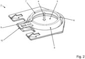
- the Figure 2 shows a detailed view of the holding device according to Figure 1 .
- the undercut 7 is formed in a nozzle 8 formed by the docking ring 6 at the inlet opening 3 and is accessible from the inside.
- the undercut 7, which is accessible from the inside, enables fastening elements of the vacuum cleaner to engage from the inside in the undercut 7 on the nozzle 8 of the docking ring 6 in a very space-saving manner. This connects the nozzle 8 to the inlet opening 3 of the filter bag 5 ( Fig.1 ) safely in the dust compartment of the with the dust bag 1 ( Fig.1 ) equipped vacuum cleaner.
- the dust bag 1 ( Fig.1 ) is securely fixed in the dust chamber simply by fastening elements of the vacuum cleaner that engage the docking ring 6 from the inside and engage in the undercut 7.
- the immersed inlet nozzle of the vacuum cleaner can be provided with a seal that seals against the docking ring 6.
- the anti-twist device 9 on the docking ring 6 can also be seen, which is designed as a semicircular indentation.
- the fastening elements of the vacuum cleaner advantageously have a projection that engages in the semicircular indentation 9. In this way, the docking ring 6 of the holding device 2 can be effectively secured against twisting when it is received in the fastening elements of the vacuum cleaner. In this way, the dust bag 1 ( Fig.1 ) remain optimally positioned in the dust chamber of the vacuum cleaner via the fastening elements of the vacuum cleaner.
- FIG 3 the holding device 2 is in accordance with Figure 2 shown in the unfolded state.
- the two partial rings 10, 11 are connected to each other via a film hinge 12.
- the partial rings 10, 11 are used to fold the docking ring 6 ( Fig.2 ) is positioned appropriately.
- the two partial rings 10, 11 forming the undercut 7 make it particularly easy to manufacture the undercut 7 ( Fig.2 ) is possible.
- the partial rings 10, 11 can be manufactured by injection molding, preferably from plastic.
- the formation of the undercut 7 from the two partial rings 10, 11 enables a particularly simple injection mold, from which the partial rings 10, 11 can be removed particularly easily.
- the two partial rings 10, 11 can then be easily attached to the film hinge 12 in one assembly step to form the undercut 7 ( Fig.2 ) in docking ring 6 ( Fig.2 ) and press them together.
- the connection between the partial rings 10, 11 can be made by gluing, screwing, hot-stitching, riveting, locking or preferably welding, so that a form-fitting holding plate connection is created. Because the partial rings 10, 11 are already positioned to match one another via the film hinge 12, the assembly step can also be carried out automatically by a machine.
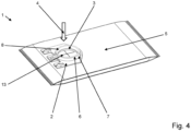
- FIG 4 A further embodiment of a dust bag 1 according to the invention is shown.
- the embodiment according to Figure 4 differs from the execution according to Figure 1 in that the undercut 7 is formed here on the nozzle 8 formed by the docking ring 6 on the inlet opening 3 and is accessible from the outside.
- This dust bag 1 also has a holding device 2 for fastening in a dust chamber of the vacuum cleaner.
- This holding device 2 also surrounds the inlet opening 3 for receiving a dust-laden air flow 4 of the vacuum cleaner. This means that the inlet opening 3 is also let into the holding device 2.
- a filter bag 5 open towards the inlet opening 3 is connected to the holding device 2.
- This filter bag 5 is also made of an air-permeable material.
- the filter bag 5 is welded to the holding device 2, preferably around the inlet opening 3.
- the filter bag 5 is welded together from a material that filters the dust out of the air flow 4 when the air flow 4 passes through.
- the filter bag 5 is also designed as a side-fold bag.
- the holding device 2 is also designed according to the invention as a docking ring 6 that surrounds the inlet opening 3.
- the docking ring 6 forms an undercut 7 that serves to attach the dust bag 1 in a vacuum cleaner.
- This provides a particularly simply constructed dust bag 1 that enables simple and secure attachment in the dust compartment of a vacuum cleaner.
- the dust bag 1 can be very easily and tightly attached to an inlet nozzle of the vacuum cleaner that extends into the inlet opening 3 using the docking ring 6.
- the inlet opening 3 is in Figure 4 also formed by a cross-slot-shaped incision 13 in the material of the filter bag 5.
- This cross-slot-shaped incision 13 in the material of the filter bag 5 replaces the otherwise usual flat punching out of the filter bag material to produce the inlet opening 3.
- the inlet nozzle of the vacuum cleaner which is guided through the docking ring 6 of the holding device 2, can easily penetrate into the filter bag 5 of the dust bag 1 via the cross-slot-shaped incision 13. This allows the dust-laden air flow of the vacuum cleaner to be directed into the dust bag 1.
- the full dust bag 1 can be changed if the inlet nozzle of the vacuum cleaner is removed from the dust bag 1; in this case, the material of the filter bag 5 forming the cross-slot 13 of the inlet opening 3 folds back when leaving the inlet nozzle and largely closes the cross-slot 13 of the inlet opening 3, so that dust can be effectively prevented from escaping using very simple means.
- the Figure 5 shows a detailed view of the holding device 2 according to Figure 4 .
- This view shows the undercut 7 in the docking ring 6 more clearly.
- the holding device 2 can be fixed axially in the flow direction of the air flow 4 through the inlet opening 3 via this undercut 7.
- the undercut 7 is accessible from the outside in the embodiment shown here on a nozzle 8 formed by the docking ring 6 on the inlet opening 3.
- This undercut 7, which is accessible from the outside allows the fastening elements of the vacuum cleaner to easily engage from the outside in the undercut 7 on the nozzle 8 of the docking ring 6.
- the nozzle 8 can be connected to the inlet opening 3 of the filter bag 5 ( Fig.4 ) easily and safely in the dust compartment of the with the dust bag 1 ( Fig.4 ) equipped vacuum cleaner.
- the illustration in Figure 5 shows that the anti-twist device 9 on the docking ring 6, which is designed as a semicircular recess, is also accessible from the outside.
- the fastening elements of the vacuum cleaner can thus engage with a projection from the outside in the semicircular recess 9.
- the docking ring 6 of the holding device 2 can be securely secured against twisting when it is received in the fastening elements of the vacuum cleaner.
- the holding device is in accordance with Figure 5 shown in the unfolded state.
- the docking ring 6 also consists of two undercuts 7 ( Fig.5 ) forming partial rings 10, 11.
- These two partial rings 10, 11 can be folded together via a film hinge 12.
- the film hinge 12 positions the partial rings 10, 11 for folding the docking ring 6 ( Fig.5 ) already fits. This makes it particularly easy to use the partial rings 10, 11 to form the undercut 7 ( Fig.5 ) forming docking ring 6 ( Fig.5 ) together.
- the production of the undercut 7 ( Fig.5 ) is so through the two undercut 7 ( Fig.5 ) forming partial rings 10, 11 is particularly easy.
- These partial rings 10, 11 can be easily manufactured by injection molding, preferably from plastic.
- the two partial rings 10, 11 enable a particularly simple injection mold.
- the partial rings 10, 11 can be removed from this mold particularly easily. Thanks to the film hinge 12, the two partial rings 10, 11 of the docking ring 6 ( Fig.5 ) as a component in an injection molding process in an injection molding tool, preferably made of plastic.
- the two partial rings 10, 11 connected via the film hinge 12 can then be easily assembled in one assembly step to form the undercut 7 ( Fig.5 ) in docking ring 6 ( Fig.5 ) are folded and pressed together at the film hinge 12. Since the partial rings 10, 11 are already positioned to match each other via the film hinge 12, the assembly step can also be carried out automatically by a simple robot.
Landscapes
- Engineering & Computer Science (AREA)
- Mechanical Engineering (AREA)
- Filters For Electric Vacuum Cleaners (AREA)
Claims (10)
- Sac à poussière (1) destiné à un aspirateur, comportant un dispositif de maintien (2) permettant la fixation dans un espace pour poussière de l'aspirateur, dans lequel une ouverture d'admission (3) permettant la réception d'un flux d'air (4) chargé de poussière de l'aspirateur est admise dans le dispositif de maintien (2), dans lequel un sac filtrant (5) ouvert vers l'ouverture d'admission (3) et constitué d'un matériau perméable à l'air est disposé sur le dispositif de maintien (2), dans lequel le matériau du sac filtrant (5) est réalisé pour filtrer la poussière du flux d'air (4) lors du passage du flux d'air (4), dans lequel le dispositif de maintien (2) est réalisé sous forme d'un élément d'amarrage (6) entourant l'ouverture d'admission (3), dans lequel l'élément d'amarrage (6) forme une contre-dépouille (7) permettant la fixation du sac à poussière (1) dans un aspirateur,
caractérisé en ce
que la contre-dépouille (7), accessible de l'intérieur, est formée dans une tubulure (8) formée par l'élément d'amarrage (6) sur l'ouverture d'admission (3). - Sac à poussière (1) selon la revendication 1, caractérisé en ce que l'élément d'amarrage (6) est réalisé sous forme d'anneau d'amarrage (6) ou de segment d'anneau d'amarrage.
- Sac à poussière (1) selon la revendication 1 ou 2, caractérisé en ce que la contre-dépouille (7) permet de fixer le dispositif de maintien (2) de manière axiale dans la direction du flux d'air (4) à travers l'ouverture d'admission (3).
- Sac à poussière (1) selon l'une des revendications 1, 2 ou 3,
caractérisé en ce que la contre-dépouille (7), accessible de l'extérieur, est formée sur une tubulure (8) formée par l'élément d'amarrage (6) sur l'ouverture d'admission (3). - Sac à poussière (1) selon l'une des revendications précédentes 1 à 4, caractérisé en ce que l'élément d'amarrage (6) présente une protection anti-rotation (9).
- Sac à poussière (1) selon la revendication 5, caractérisé en ce que la protection anti-rotation (9) est formée par une encoche semi-circulaire.
- Sac à poussière (1) selon l'une des revendications 1 à 6,
caractérisé en ce que l'anneau d'amarrage (6) est composé de deux anneaux partiels (10, 11) formant la contre-dépouille (7). - Sac à poussière (1) selon l'une des revendications 1 à 7,
caractérisé en ce que les anneaux partiels (10, 11) sont reliés par l'intermédiaire d'une charnière à film (12), dans lequel la charnière à film (12) positionne les anneaux partiels (10, 11) de manière adaptée pour le repliage de l'anneau d'amarrage (6). - Sac à poussière (1) selon l'une des revendications 1 à 8,
caractérisé en ce que l'ouverture d'admission (3) est formée par au moins une incision (13) en forme de fente dans le matériau du sac filtrant (5). - Sac à poussière (1) selon la revendication 9, caractérisé en ce que l'incision (13) dans le matériau du sac filtrant (5) pour l'ouverture d'admission (3) est réalisée en forme de U, de croix, d'étoile, de ligne droite ou de ligne circulaire.
Applications Claiming Priority (1)
| Application Number | Priority Date | Filing Date | Title |
|---|---|---|---|
| DE102021121083.6A DE102021121083A1 (de) | 2021-08-13 | 2021-08-13 | Staubbeutel |
Publications (2)
| Publication Number | Publication Date |
|---|---|
| EP4133983A1 EP4133983A1 (fr) | 2023-02-15 |
| EP4133983B1 true EP4133983B1 (fr) | 2024-06-26 |
Family
ID=82748419
Family Applications (1)
| Application Number | Title | Priority Date | Filing Date |
|---|---|---|---|
| EP22187236.9A Active EP4133983B1 (fr) | 2021-08-13 | 2022-07-27 | Sac à poussière |
Country Status (2)
| Country | Link |
|---|---|
| EP (1) | EP4133983B1 (fr) |
| DE (1) | DE102021121083A1 (fr) |
Citations (10)
| Publication number | Priority date | Publication date | Assignee | Title |
|---|---|---|---|---|
| DE929810C (de) | 1939-12-23 | 1955-07-04 | Hoover Ltd | Staubbeutel fuer Staubsauger |
| US4299605A (en) | 1980-05-19 | 1981-11-10 | Kioritz Corporation | Collecting filter bag |
| DE4221700A1 (de) | 1992-03-04 | 1993-09-16 | Branofilter Gmbh | Anschlussstueck eines filtersacks fuer staubabsaugende geraete |
| EP1932460A1 (fr) | 2006-12-15 | 2008-06-18 | Eurofilters Holding N.V | Dispositif d'adaptateur pour un sac d'aspirateur |
| DE202010015038U1 (de) | 2009-11-27 | 2011-01-27 | Haider, Wolfgang | Staubbehälter für Staubsauger |
| DE202008018054U1 (de) | 2008-08-29 | 2011-04-28 | Vorwerk & Co. Interholding Gmbh | Filterbeutel für einen Staubsauger |
| DE102012010079A1 (de) | 2011-05-25 | 2012-11-29 | Branofilter Gmbh | Kupplungseinrichtung zur Kupplung eines Staubfilterbeutels mit einer Einlaßeinrichtung eines Staubsaugers |
| EP2772172A2 (fr) | 2013-02-28 | 2014-09-03 | Wolf PVG GmbH & Co. KG | Plaque de support et procédé de fabrication d'une plaque de support |
| EP2772173A1 (fr) | 2013-02-28 | 2014-09-03 | Wolf PVG GmbH & Co. KG | Sac filtrant pour un aspirateur et procédé de fabrication d'une plaque de support pour un sac filtrant |
| DE202014100563U1 (de) | 2014-02-10 | 2015-05-15 | Wolf Pvg Gmbh & Co. Kg | Staubsaugerbeutel |
Family Cites Families (3)
| Publication number | Priority date | Publication date | Assignee | Title |
|---|---|---|---|---|
| EP0433439B1 (fr) * | 1989-07-11 | 1997-01-29 | The Scott Fetzer Company | Aspirateur avec systeme de montage particulier pour sacs a poussiere jetables |
| US5792224A (en) * | 1997-01-23 | 1998-08-11 | The Scott Fetzer Company | Connector system |
| ITVI20120079A1 (it) * | 2012-04-04 | 2013-10-05 | Ametera S R L | Sacco permeabile all'aria e piastra di raccordo per detto sacco e gruppo separatore di polvere perfezionato per aspirapolvere utilizzante detto sacco e detta piastra |
-
2021
- 2021-08-13 DE DE102021121083.6A patent/DE102021121083A1/de active Pending
-
2022
- 2022-07-27 EP EP22187236.9A patent/EP4133983B1/fr active Active
Patent Citations (10)
| Publication number | Priority date | Publication date | Assignee | Title |
|---|---|---|---|---|
| DE929810C (de) | 1939-12-23 | 1955-07-04 | Hoover Ltd | Staubbeutel fuer Staubsauger |
| US4299605A (en) | 1980-05-19 | 1981-11-10 | Kioritz Corporation | Collecting filter bag |
| DE4221700A1 (de) | 1992-03-04 | 1993-09-16 | Branofilter Gmbh | Anschlussstueck eines filtersacks fuer staubabsaugende geraete |
| EP1932460A1 (fr) | 2006-12-15 | 2008-06-18 | Eurofilters Holding N.V | Dispositif d'adaptateur pour un sac d'aspirateur |
| DE202008018054U1 (de) | 2008-08-29 | 2011-04-28 | Vorwerk & Co. Interholding Gmbh | Filterbeutel für einen Staubsauger |
| DE202010015038U1 (de) | 2009-11-27 | 2011-01-27 | Haider, Wolfgang | Staubbehälter für Staubsauger |
| DE102012010079A1 (de) | 2011-05-25 | 2012-11-29 | Branofilter Gmbh | Kupplungseinrichtung zur Kupplung eines Staubfilterbeutels mit einer Einlaßeinrichtung eines Staubsaugers |
| EP2772172A2 (fr) | 2013-02-28 | 2014-09-03 | Wolf PVG GmbH & Co. KG | Plaque de support et procédé de fabrication d'une plaque de support |
| EP2772173A1 (fr) | 2013-02-28 | 2014-09-03 | Wolf PVG GmbH & Co. KG | Sac filtrant pour un aspirateur et procédé de fabrication d'une plaque de support pour un sac filtrant |
| DE202014100563U1 (de) | 2014-02-10 | 2015-05-15 | Wolf Pvg Gmbh & Co. Kg | Staubsaugerbeutel |
Also Published As
| Publication number | Publication date |
|---|---|
| DE102021121083A1 (de) | 2023-02-16 |
| EP4133983A1 (fr) | 2023-02-15 |
Similar Documents
| Publication | Publication Date | Title |
|---|---|---|
| DE112012000251B4 (de) | Staubbehälter für Staubsauger | |
| EP2866633B1 (fr) | Association d'un aspirateur à main et un manche pour accueillir l'aspirateur à main | |
| EP2866631B1 (fr) | Combinaison d'un mini-aspirateur et d'un boîtier d'aspirateur ainsi que mini-aspirateur et boîtier d'aspirateur | |
| DE112009002152T5 (de) | Beutelankoppelanordnung für einen Staubsauger | |
| DE102016118807A1 (de) | Rückspülbarer Luftfilter und Staubsauger mit einem rückspülbaren Luftfilter | |
| DE102014119190A1 (de) | Saugdüse für einen elektromotorisch betriebenen Staubsauger | |
| EP2866632B1 (fr) | Combinaison composée d'un mini-aspirateur et d'un bâti d'aspirateur-balai, ainsi que mini-aspirateur et bâti d'aspirateur-balai | |
| DE102012100050A1 (de) | Staubsammelbehälter für einen Akkutischsauger mit einem solchen Staubsammelbehälter | |
| EP4133983B1 (fr) | Sac à poussière | |
| CH615618A5 (en) | Drilling tool having a dust-collecting hood | |
| DE69029843T2 (de) | Staubsauger mit speziellem anschluss fuer wegwerfstaubsack | |
| EP4070709B1 (fr) | Unité de dépoussiérage pour robot aspirateur et aspirateur robot | |
| EP4154782B1 (fr) | Aspirateur et sac à poussière | |
| EP4133984B1 (fr) | Module de retrait du sac à poussière et aspirateur | |
| DE102019102357B4 (de) | Vorrichtung zur Absperrung oder Steuerung des Durchflusses von schmutzbeladener Luft, Reinigungsgerät und Behältnis zum Abtrennen und/oder Sammeln von Schmutz mit einer solchen Vorrichtung | |
| EP2954815A1 (fr) | Aspirateur doté d'un filtre amovible et filtre pouvant être utilisé dans un tel aspirateur | |
| DE102009048852A1 (de) | Saugdüse für ein Saugaggregat oder einstellbares Filtrierungselement | |
| EP3944801B1 (fr) | Appareil autonome de nettoyage du sol | |
| EP4072389B1 (fr) | Dispositif d'aspiration, en particulier aspirateur | |
| EP4467057A1 (fr) | Dispositif destiné à être utilisé comme accessoire d'un appareil de nettoyage de sol | |
| DE102021100072A1 (de) | Staubsauger | |
| DE202005002488U1 (de) | Staubsauger | |
| DE102015100873A1 (de) | Saugdüse | |
| DE102018109170A1 (de) | Staubsauger | |
| EP3622870A1 (fr) | Buse de sol dotée d'un syst?me de roue, aspirateur doté d'une buse de sol et procédé de fabrication d'une buse de sol |
Legal Events
| Date | Code | Title | Description |
|---|---|---|---|
| PUAI | Public reference made under article 153(3) epc to a published international application that has entered the european phase |
Free format text: ORIGINAL CODE: 0009012 |
|
| STAA | Information on the status of an ep patent application or granted ep patent |
Free format text: STATUS: THE APPLICATION HAS BEEN PUBLISHED |
|
| AK | Designated contracting states |
Kind code of ref document: A1 Designated state(s): AL AT BE BG CH CY CZ DE DK EE ES FI FR GB GR HR HU IE IS IT LI LT LU LV MC MK MT NL NO PL PT RO RS SE SI SK SM TR |
|
| STAA | Information on the status of an ep patent application or granted ep patent |
Free format text: STATUS: REQUEST FOR EXAMINATION WAS MADE |
|
| 17P | Request for examination filed |
Effective date: 20230816 |
|
| RBV | Designated contracting states (corrected) |
Designated state(s): AL AT BE BG CH CY CZ DE DK EE ES FI FR GB GR HR HU IE IS IT LI LT LU LV MC MK MT NL NO PL PT RO RS SE SI SK SM TR |
|
| RIC1 | Information provided on ipc code assigned before grant |
Ipc: A47L 9/14 20060101AFI20240126BHEP |
|
| GRAP | Despatch of communication of intention to grant a patent |
Free format text: ORIGINAL CODE: EPIDOSNIGR1 |
|
| STAA | Information on the status of an ep patent application or granted ep patent |
Free format text: STATUS: GRANT OF PATENT IS INTENDED |
|
| INTG | Intention to grant announced |
Effective date: 20240318 |
|
| GRAS | Grant fee paid |
Free format text: ORIGINAL CODE: EPIDOSNIGR3 |
|
| GRAA | (expected) grant |
Free format text: ORIGINAL CODE: 0009210 |
|
| STAA | Information on the status of an ep patent application or granted ep patent |
Free format text: STATUS: THE PATENT HAS BEEN GRANTED |
|
| AK | Designated contracting states |
Kind code of ref document: B1 Designated state(s): AL AT BE BG CH CY CZ DE DK EE ES FI FR GB GR HR HU IE IS IT LI LT LU LV MC MK MT NL NO PL PT RO RS SE SI SK SM TR |
|
| REG | Reference to a national code |
Ref country code: GB Ref legal event code: FG4D Free format text: NOT ENGLISH |
|
| REG | Reference to a national code |
Ref country code: CH Ref legal event code: EP |
|
| REG | Reference to a national code |
Ref country code: DE Ref legal event code: R096 Ref document number: 502022001113 Country of ref document: DE |
|
| PG25 | Lapsed in a contracting state [announced via postgrant information from national office to epo] |
Ref country code: BG Free format text: LAPSE BECAUSE OF FAILURE TO SUBMIT A TRANSLATION OF THE DESCRIPTION OR TO PAY THE FEE WITHIN THE PRESCRIBED TIME-LIMIT Effective date: 20240626 |
|
| PG25 | Lapsed in a contracting state [announced via postgrant information from national office to epo] |
Ref country code: HR Free format text: LAPSE BECAUSE OF FAILURE TO SUBMIT A TRANSLATION OF THE DESCRIPTION OR TO PAY THE FEE WITHIN THE PRESCRIBED TIME-LIMIT Effective date: 20240626 Ref country code: FI Free format text: LAPSE BECAUSE OF FAILURE TO SUBMIT A TRANSLATION OF THE DESCRIPTION OR TO PAY THE FEE WITHIN THE PRESCRIBED TIME-LIMIT Effective date: 20240626 |
|
| REG | Reference to a national code |
Ref country code: LT Ref legal event code: MG9D |
|
| PG25 | Lapsed in a contracting state [announced via postgrant information from national office to epo] |
Ref country code: GR Free format text: LAPSE BECAUSE OF FAILURE TO SUBMIT A TRANSLATION OF THE DESCRIPTION OR TO PAY THE FEE WITHIN THE PRESCRIBED TIME-LIMIT Effective date: 20240927 |
|
| PG25 | Lapsed in a contracting state [announced via postgrant information from national office to epo] |
Ref country code: LV Free format text: LAPSE BECAUSE OF FAILURE TO SUBMIT A TRANSLATION OF THE DESCRIPTION OR TO PAY THE FEE WITHIN THE PRESCRIBED TIME-LIMIT Effective date: 20240626 |
|
| REG | Reference to a national code |
Ref country code: NL Ref legal event code: MP Effective date: 20240626 |
|
| PG25 | Lapsed in a contracting state [announced via postgrant information from national office to epo] |
Ref country code: NO Free format text: LAPSE BECAUSE OF FAILURE TO SUBMIT A TRANSLATION OF THE DESCRIPTION OR TO PAY THE FEE WITHIN THE PRESCRIBED TIME-LIMIT Effective date: 20240926 Ref country code: LV Free format text: LAPSE BECAUSE OF FAILURE TO SUBMIT A TRANSLATION OF THE DESCRIPTION OR TO PAY THE FEE WITHIN THE PRESCRIBED TIME-LIMIT Effective date: 20240626 Ref country code: HR Free format text: LAPSE BECAUSE OF FAILURE TO SUBMIT A TRANSLATION OF THE DESCRIPTION OR TO PAY THE FEE WITHIN THE PRESCRIBED TIME-LIMIT Effective date: 20240626 Ref country code: GR Free format text: LAPSE BECAUSE OF FAILURE TO SUBMIT A TRANSLATION OF THE DESCRIPTION OR TO PAY THE FEE WITHIN THE PRESCRIBED TIME-LIMIT Effective date: 20240927 Ref country code: FI Free format text: LAPSE BECAUSE OF FAILURE TO SUBMIT A TRANSLATION OF THE DESCRIPTION OR TO PAY THE FEE WITHIN THE PRESCRIBED TIME-LIMIT Effective date: 20240626 Ref country code: BG Free format text: LAPSE BECAUSE OF FAILURE TO SUBMIT A TRANSLATION OF THE DESCRIPTION OR TO PAY THE FEE WITHIN THE PRESCRIBED TIME-LIMIT Effective date: 20240626 Ref country code: RS Free format text: LAPSE BECAUSE OF FAILURE TO SUBMIT A TRANSLATION OF THE DESCRIPTION OR TO PAY THE FEE WITHIN THE PRESCRIBED TIME-LIMIT Effective date: 20240926 |
|
| PG25 | Lapsed in a contracting state [announced via postgrant information from national office to epo] |
Ref country code: NL Free format text: LAPSE BECAUSE OF FAILURE TO SUBMIT A TRANSLATION OF THE DESCRIPTION OR TO PAY THE FEE WITHIN THE PRESCRIBED TIME-LIMIT Effective date: 20240626 |
|
| PG25 | Lapsed in a contracting state [announced via postgrant information from national office to epo] |
Ref country code: NL Free format text: LAPSE BECAUSE OF FAILURE TO SUBMIT A TRANSLATION OF THE DESCRIPTION OR TO PAY THE FEE WITHIN THE PRESCRIBED TIME-LIMIT Effective date: 20240626 |
|
| PG25 | Lapsed in a contracting state [announced via postgrant information from national office to epo] |
Ref country code: PT Free format text: LAPSE BECAUSE OF FAILURE TO SUBMIT A TRANSLATION OF THE DESCRIPTION OR TO PAY THE FEE WITHIN THE PRESCRIBED TIME-LIMIT Effective date: 20241028 |
|
| PG25 | Lapsed in a contracting state [announced via postgrant information from national office to epo] |
Ref country code: PT Free format text: LAPSE BECAUSE OF FAILURE TO SUBMIT A TRANSLATION OF THE DESCRIPTION OR TO PAY THE FEE WITHIN THE PRESCRIBED TIME-LIMIT Effective date: 20241028 |
|
| PG25 | Lapsed in a contracting state [announced via postgrant information from national office to epo] |
Ref country code: PL Free format text: LAPSE BECAUSE OF FAILURE TO SUBMIT A TRANSLATION OF THE DESCRIPTION OR TO PAY THE FEE WITHIN THE PRESCRIBED TIME-LIMIT Effective date: 20240626 |
|
| PG25 | Lapsed in a contracting state [announced via postgrant information from national office to epo] |
Ref country code: EE Free format text: LAPSE BECAUSE OF FAILURE TO SUBMIT A TRANSLATION OF THE DESCRIPTION OR TO PAY THE FEE WITHIN THE PRESCRIBED TIME-LIMIT Effective date: 20240626 |
|
| PG25 | Lapsed in a contracting state [announced via postgrant information from national office to epo] |
Ref country code: IS Free format text: LAPSE BECAUSE OF FAILURE TO SUBMIT A TRANSLATION OF THE DESCRIPTION OR TO PAY THE FEE WITHIN THE PRESCRIBED TIME-LIMIT Effective date: 20241026 |
|
| PG25 | Lapsed in a contracting state [announced via postgrant information from national office to epo] |
Ref country code: CZ Free format text: LAPSE BECAUSE OF FAILURE TO SUBMIT A TRANSLATION OF THE DESCRIPTION OR TO PAY THE FEE WITHIN THE PRESCRIBED TIME-LIMIT Effective date: 20240626 |
|
| PG25 | Lapsed in a contracting state [announced via postgrant information from national office to epo] |
Ref country code: RO Free format text: LAPSE BECAUSE OF FAILURE TO SUBMIT A TRANSLATION OF THE DESCRIPTION OR TO PAY THE FEE WITHIN THE PRESCRIBED TIME-LIMIT Effective date: 20240626 Ref country code: SK Free format text: LAPSE BECAUSE OF FAILURE TO SUBMIT A TRANSLATION OF THE DESCRIPTION OR TO PAY THE FEE WITHIN THE PRESCRIBED TIME-LIMIT Effective date: 20240626 |
|
| PG25 | Lapsed in a contracting state [announced via postgrant information from national office to epo] |
Ref country code: SM Free format text: LAPSE BECAUSE OF FAILURE TO SUBMIT A TRANSLATION OF THE DESCRIPTION OR TO PAY THE FEE WITHIN THE PRESCRIBED TIME-LIMIT Effective date: 20240626 Ref country code: ES Free format text: LAPSE BECAUSE OF FAILURE TO SUBMIT A TRANSLATION OF THE DESCRIPTION OR TO PAY THE FEE WITHIN THE PRESCRIBED TIME-LIMIT Effective date: 20240626 |
|
| PG25 | Lapsed in a contracting state [announced via postgrant information from national office to epo] |
Ref country code: SM Free format text: LAPSE BECAUSE OF FAILURE TO SUBMIT A TRANSLATION OF THE DESCRIPTION OR TO PAY THE FEE WITHIN THE PRESCRIBED TIME-LIMIT Effective date: 20240626 Ref country code: SK Free format text: LAPSE BECAUSE OF FAILURE TO SUBMIT A TRANSLATION OF THE DESCRIPTION OR TO PAY THE FEE WITHIN THE PRESCRIBED TIME-LIMIT Effective date: 20240626 Ref country code: RO Free format text: LAPSE BECAUSE OF FAILURE TO SUBMIT A TRANSLATION OF THE DESCRIPTION OR TO PAY THE FEE WITHIN THE PRESCRIBED TIME-LIMIT Effective date: 20240626 Ref country code: PL Free format text: LAPSE BECAUSE OF FAILURE TO SUBMIT A TRANSLATION OF THE DESCRIPTION OR TO PAY THE FEE WITHIN THE PRESCRIBED TIME-LIMIT Effective date: 20240626 Ref country code: IS Free format text: LAPSE BECAUSE OF FAILURE TO SUBMIT A TRANSLATION OF THE DESCRIPTION OR TO PAY THE FEE WITHIN THE PRESCRIBED TIME-LIMIT Effective date: 20241026 Ref country code: ES Free format text: LAPSE BECAUSE OF FAILURE TO SUBMIT A TRANSLATION OF THE DESCRIPTION OR TO PAY THE FEE WITHIN THE PRESCRIBED TIME-LIMIT Effective date: 20240626 Ref country code: EE Free format text: LAPSE BECAUSE OF FAILURE TO SUBMIT A TRANSLATION OF THE DESCRIPTION OR TO PAY THE FEE WITHIN THE PRESCRIBED TIME-LIMIT Effective date: 20240626 Ref country code: CZ Free format text: LAPSE BECAUSE OF FAILURE TO SUBMIT A TRANSLATION OF THE DESCRIPTION OR TO PAY THE FEE WITHIN THE PRESCRIBED TIME-LIMIT Effective date: 20240626 |
|
| PG25 | Lapsed in a contracting state [announced via postgrant information from national office to epo] |
Ref country code: IT Free format text: LAPSE BECAUSE OF FAILURE TO SUBMIT A TRANSLATION OF THE DESCRIPTION OR TO PAY THE FEE WITHIN THE PRESCRIBED TIME-LIMIT Effective date: 20240626 |
|
| PG25 | Lapsed in a contracting state [announced via postgrant information from national office to epo] |
Ref country code: LU Free format text: LAPSE BECAUSE OF NON-PAYMENT OF DUE FEES Effective date: 20240727 |
|
| PG25 | Lapsed in a contracting state [announced via postgrant information from national office to epo] |
Ref country code: MC Free format text: LAPSE BECAUSE OF FAILURE TO SUBMIT A TRANSLATION OF THE DESCRIPTION OR TO PAY THE FEE WITHIN THE PRESCRIBED TIME-LIMIT Effective date: 20240626 |
|
| REG | Reference to a national code |
Ref country code: DE Ref legal event code: R026 Ref document number: 502022001113 Country of ref document: DE |
|
| PLBI | Opposition filed |
Free format text: ORIGINAL CODE: 0009260 |
|
| PG25 | Lapsed in a contracting state [announced via postgrant information from national office to epo] |
Ref country code: MC Free format text: LAPSE BECAUSE OF FAILURE TO SUBMIT A TRANSLATION OF THE DESCRIPTION OR TO PAY THE FEE WITHIN THE PRESCRIBED TIME-LIMIT Effective date: 20240626 Ref country code: LU Free format text: LAPSE BECAUSE OF NON-PAYMENT OF DUE FEES Effective date: 20240727 |
|
| PLAX | Notice of opposition and request to file observation + time limit sent |
Free format text: ORIGINAL CODE: EPIDOSNOBS2 |
|
| PG25 | Lapsed in a contracting state [announced via postgrant information from national office to epo] |
Ref country code: DK Free format text: LAPSE BECAUSE OF FAILURE TO SUBMIT A TRANSLATION OF THE DESCRIPTION OR TO PAY THE FEE WITHIN THE PRESCRIBED TIME-LIMIT Effective date: 20240626 |
|
| PG25 | Lapsed in a contracting state [announced via postgrant information from national office to epo] |
Ref country code: BE Free format text: LAPSE BECAUSE OF NON-PAYMENT OF DUE FEES Effective date: 20240731 |
|
| 26 | Opposition filed |
Opponent name: WOLF PVG GMBH & CO. KG Effective date: 20250324 |
|
| REG | Reference to a national code |
Ref country code: BE Ref legal event code: MM Effective date: 20240731 |
|
| PG25 | Lapsed in a contracting state [announced via postgrant information from national office to epo] |
Ref country code: IE Free format text: LAPSE BECAUSE OF NON-PAYMENT OF DUE FEES Effective date: 20240727 |
|
| PLBB | Reply of patent proprietor to notice(s) of opposition received |
Free format text: ORIGINAL CODE: EPIDOSNOBS3 |
|
| PG25 | Lapsed in a contracting state [announced via postgrant information from national office to epo] |
Ref country code: SE Free format text: LAPSE BECAUSE OF FAILURE TO SUBMIT A TRANSLATION OF THE DESCRIPTION OR TO PAY THE FEE WITHIN THE PRESCRIBED TIME-LIMIT Effective date: 20240626 |
|
| PGFP | Annual fee paid to national office [announced via postgrant information from national office to epo] |
Ref country code: DE Payment date: 20250731 Year of fee payment: 4 |
|
| PGFP | Annual fee paid to national office [announced via postgrant information from national office to epo] |
Ref country code: FR Payment date: 20250725 Year of fee payment: 4 Ref country code: AT Payment date: 20251020 Year of fee payment: 4 |
|
| PG25 | Lapsed in a contracting state [announced via postgrant information from national office to epo] |
Ref country code: CY Free format text: LAPSE BECAUSE OF FAILURE TO SUBMIT A TRANSLATION OF THE DESCRIPTION OR TO PAY THE FEE WITHIN THE PRESCRIBED TIME-LIMIT; INVALID AB INITIO Effective date: 20220727 |
|
| REG | Reference to a national code |
Ref country code: CH Ref legal event code: H13 Free format text: ST27 STATUS EVENT CODE: U-0-0-H10-H13 (AS PROVIDED BY THE NATIONAL OFFICE) Effective date: 20260224 |
|
| PG25 | Lapsed in a contracting state [announced via postgrant information from national office to epo] |
Ref country code: HU Free format text: LAPSE BECAUSE OF FAILURE TO SUBMIT A TRANSLATION OF THE DESCRIPTION OR TO PAY THE FEE WITHIN THE PRESCRIBED TIME-LIMIT; INVALID AB INITIO Effective date: 20220727 |
|
| PG25 | Lapsed in a contracting state [announced via postgrant information from national office to epo] |
Ref country code: CH Free format text: LAPSE BECAUSE OF NON-PAYMENT OF DUE FEES Effective date: 20250731 |