EP2954832A1 - Einsetzvorrichtung - Google Patents
Einsetzvorrichtung Download PDFInfo
- Publication number
- EP2954832A1 EP2954832A1 EP14749477.7A EP14749477A EP2954832A1 EP 2954832 A1 EP2954832 A1 EP 2954832A1 EP 14749477 A EP14749477 A EP 14749477A EP 2954832 A1 EP2954832 A1 EP 2954832A1
- Authority
- EP
- European Patent Office
- Prior art keywords
- section
- bending
- bending operation
- rotating member
- driving force
- Prior art date
- Legal status (The legal status is an assumption and is not a legal conclusion. Google has not performed a legal analysis and makes no representation as to the accuracy of the status listed.)
- Withdrawn
Links
- 238000003780 insertion Methods 0.000 title claims abstract description 21
- 230000037431 insertion Effects 0.000 title claims abstract description 21
- 230000005540 biological transmission Effects 0.000 claims abstract description 20
- 238000005452 bending Methods 0.000 claims description 231
- 230000007257 malfunction Effects 0.000 description 10
- 210000003811 finger Anatomy 0.000 description 5
- 238000003384 imaging method Methods 0.000 description 5
- 238000001514 detection method Methods 0.000 description 3
- 238000012986 modification Methods 0.000 description 3
- 230000004048 modification Effects 0.000 description 3
- 238000010586 diagram Methods 0.000 description 2
- 230000000694 effects Effects 0.000 description 2
- 230000000149 penetrating effect Effects 0.000 description 2
- 230000002093 peripheral effect Effects 0.000 description 2
- 210000003813 thumb Anatomy 0.000 description 2
- UHOVQNZJYSORNB-UHFFFAOYSA-N c1ccccc1 Chemical compound c1ccccc1 UHOVQNZJYSORNB-UHFFFAOYSA-N 0.000 description 1
- 230000008878 coupling Effects 0.000 description 1
- 238000010168 coupling process Methods 0.000 description 1
- 238000005859 coupling reaction Methods 0.000 description 1
- 210000004932 little finger Anatomy 0.000 description 1
Images



Classifications
-
- A—HUMAN NECESSITIES
- A61—MEDICAL OR VETERINARY SCIENCE; HYGIENE
- A61B—DIAGNOSIS; SURGERY; IDENTIFICATION
- A61B1/00—Instruments for performing medical examinations of the interior of cavities or tubes of the body by visual or photographical inspection, e.g. endoscopes; Illuminating arrangements therefor
- A61B1/005—Flexible endoscopes
- A61B1/0051—Flexible endoscopes with controlled bending of insertion part
- A61B1/0052—Constructional details of control elements, e.g. handles
-
- A—HUMAN NECESSITIES
- A61—MEDICAL OR VETERINARY SCIENCE; HYGIENE
- A61B—DIAGNOSIS; SURGERY; IDENTIFICATION
- A61B1/00—Instruments for performing medical examinations of the interior of cavities or tubes of the body by visual or photographical inspection, e.g. endoscopes; Illuminating arrangements therefor
- A61B1/005—Flexible endoscopes
- A61B1/0051—Flexible endoscopes with controlled bending of insertion part
-
- A—HUMAN NECESSITIES
- A61—MEDICAL OR VETERINARY SCIENCE; HYGIENE
- A61B—DIAGNOSIS; SURGERY; IDENTIFICATION
- A61B1/00—Instruments for performing medical examinations of the interior of cavities or tubes of the body by visual or photographical inspection, e.g. endoscopes; Illuminating arrangements therefor
- A61B1/00147—Holding or positioning arrangements
- A61B1/0016—Holding or positioning arrangements using motor drive units
-
- A—HUMAN NECESSITIES
- A61—MEDICAL OR VETERINARY SCIENCE; HYGIENE
- A61B—DIAGNOSIS; SURGERY; IDENTIFICATION
- A61B1/00—Instruments for performing medical examinations of the interior of cavities or tubes of the body by visual or photographical inspection, e.g. endoscopes; Illuminating arrangements therefor
- A61B1/005—Flexible endoscopes
- A61B1/0051—Flexible endoscopes with controlled bending of insertion part
- A61B1/0057—Constructional details of force transmission elements, e.g. control wires
-
- A—HUMAN NECESSITIES
- A61—MEDICAL OR VETERINARY SCIENCE; HYGIENE
- A61B—DIAGNOSIS; SURGERY; IDENTIFICATION
- A61B1/00—Instruments for performing medical examinations of the interior of cavities or tubes of the body by visual or photographical inspection, e.g. endoscopes; Illuminating arrangements therefor
- A61B1/04—Instruments for performing medical examinations of the interior of cavities or tubes of the body by visual or photographical inspection, e.g. endoscopes; Illuminating arrangements therefor combined with photographic or television appliances
- A61B1/05—Instruments for performing medical examinations of the interior of cavities or tubes of the body by visual or photographical inspection, e.g. endoscopes; Illuminating arrangements therefor combined with photographic or television appliances characterised by the image sensor, e.g. camera, being in the distal end portion
-
- A—HUMAN NECESSITIES
- A61—MEDICAL OR VETERINARY SCIENCE; HYGIENE
- A61M—DEVICES FOR INTRODUCING MEDIA INTO, OR ONTO, THE BODY; DEVICES FOR TRANSDUCING BODY MEDIA OR FOR TAKING MEDIA FROM THE BODY; DEVICES FOR PRODUCING OR ENDING SLEEP OR STUPOR
- A61M25/00—Catheters; Hollow probes
- A61M25/01—Introducing, guiding, advancing, emplacing or holding catheters
- A61M25/0105—Steering means as part of the catheter or advancing means; Markers for positioning
- A61M25/0133—Tip steering devices
- A61M25/0136—Handles therefor
-
- A—HUMAN NECESSITIES
- A61—MEDICAL OR VETERINARY SCIENCE; HYGIENE
- A61M—DEVICES FOR INTRODUCING MEDIA INTO, OR ONTO, THE BODY; DEVICES FOR TRANSDUCING BODY MEDIA OR FOR TAKING MEDIA FROM THE BODY; DEVICES FOR PRODUCING OR ENDING SLEEP OR STUPOR
- A61M25/00—Catheters; Hollow probes
- A61M25/01—Introducing, guiding, advancing, emplacing or holding catheters
- A61M25/0105—Steering means as part of the catheter or advancing means; Markers for positioning
- A61M25/0133—Tip steering devices
- A61M25/0147—Tip steering devices with movable mechanical means, e.g. pull wires
-
- F—MECHANICAL ENGINEERING; LIGHTING; HEATING; WEAPONS; BLASTING
- F16—ENGINEERING ELEMENTS AND UNITS; GENERAL MEASURES FOR PRODUCING AND MAINTAINING EFFECTIVE FUNCTIONING OF MACHINES OR INSTALLATIONS; THERMAL INSULATION IN GENERAL
- F16D—COUPLINGS FOR TRANSMITTING ROTATION; CLUTCHES; BRAKES
- F16D11/00—Clutches in which the members have interengaging parts
-
- F—MECHANICAL ENGINEERING; LIGHTING; HEATING; WEAPONS; BLASTING
- F16—ENGINEERING ELEMENTS AND UNITS; GENERAL MEASURES FOR PRODUCING AND MAINTAINING EFFECTIVE FUNCTIONING OF MACHINES OR INSTALLATIONS; THERMAL INSULATION IN GENERAL
- F16D—COUPLINGS FOR TRANSMITTING ROTATION; CLUTCHES; BRAKES
- F16D11/00—Clutches in which the members have interengaging parts
- F16D11/14—Clutches in which the members have interengaging parts with clutching members movable only axially
Definitions
- the present invention relates to an insertion device wherein a bending section is provided in an inserting section, and the bending section is bendable in first bending directions perpendicular to a longitudinal axis and in second bending directions perpendicular to a longitudinal axis and the first bending directions.
- Patent Literature 1 discloses an endoscope which is an insertion device, wherein a bending section is provided to an inserting section, and the bending section is bendable in bending LR directions (first bending directions) perpendicular to a longitudinal axis and in bending UD directions (second bending directions) perpendicular to a longitudinal axis and the first bending directions.
- a bending operation knob which acts as a manual bending operating section is coupled to a held section casing of a held section, the held section being provided to the proximal end side of an inserting section.
- a bending operation dial which acts as an electric bending operating section is coupled to the held section casing.
- a motor which acts as a driving member is driven by inputting an electric bending operation with the bending operation dial.
- an electrical driving force from the motor is transmitted to a first rotating member which is a sprocket, etc. provided inside the held section casing, and the first rotating member rotates.
- first linear portions such as bending wires, etc. which are extended inside the inserting section
- second rotating member such as a sprocket, etc. provided inside the held section casing
- Patent Literature 1 International Publication No. 2012/074013
- the present invention was designed to address the above problem, and the purpose of the present invention is to provide an insertion device that can bend the bending section properly without driving an electric driving member when any malfunction occurs at the driving member.
- an insertion device includes that: an inserting section which is extended along a longitudinal axis, the inserting section including a bending section which is bendable in first bending directions perpendicular to a longitudinal axis and in second bending directions perpendicular to the longitudinal axis and perpendicular to the first bending directions; a held section including a held section casing as an exterior part, the held section being arranged to a proximal direction side of the inserting section; a first linear portion which is extended inside the inserting section along the longitudinal axis, and which is connected to the bending section at a distal end thereof, the first linear portion being configured to bend the bending section toward one of the first bending directions upon being pulled; a second linear portion which is extended inside the inserting section along the longitudinal axis, and which is connected to the bending section at a distal end thereof, the second linear portion being configured to bend the bending section toward one of the second bending directions upon being pulled; a first linear portion which is extended inside the inserting section along the
- an insertion device which can bend the bending section properly without driving an electric driving member when any malfunction occurs at the driving member, can be provided.
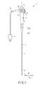
- FIG. 1 shows an endoscope 1 as an insertion device.
- FIG. 2 shows a system in which the endoscope 1 is adopted.
- the endoscope 1 has a longitudinal axis C as shown in FIG. 1 .
- One of directions parallel to the longitudinal axis C is defined as a distal direction (indicated by the arrow C1 in FIG. 1 ), and the other of the directions parallel to the longitudinal axis C is defined as a proximal direction (indicated by the arrow C2 in FIG. 1 ).
- the endoscope 1 includes an elongated inserting section 2 extended along the longitudinal axis C, and a held section 3 provided to the proximal direction side of the inserting section 2.
- the inserting section 2 includes a distal rigid section 5, a bending section 6 provided to the proximal direction side with respect to the distal rigid section 5, and a flexible tube section 7 provided to the proximal direction side of the bending section 6.
- the bending section 6 is bendable in first bending directions (i.e., the directions indicated by the arrows L and R in FIG. 1 ) perpendicular to the longitudinal axis C.
- the bending section 6 is bendable in second bending directions (i.e., the directions indicated by the arrows U and D in FIG. 1 ) perpendicular to the longitudinal axis C and the first bending directions.
- the first bending directions are the bending LR directions
- the second bending directions are the bending UD directions.
- the flexible tube section 7 is elongated and flexible.
- the held section 3 includes a held section casing 8 as an exterior.
- One end of a universal cord 10 is coupled to the held section 3.
- a scope connector 11 is provided to the other end of the universal cord 10.
- the universal cord 10 is coupled to peripheral units, such as an image processing unit 12, a light source unit 13, a controlling unit 15, etc., via the scope connector 11.
- the image processing unit 12 is electrically connected to a display section 17 of a monitor, etc.
- the distal rigid section 5 of the inserting section 2 is provided with an imaging element 19, such as CCD, etc.
- an imaging cable 21 is connected to the imaging element 19.
- the other end of the imaging cable 21 is coupled to the image processing unit 12 via the scope connector 11 and the imaging cable pass through the inside of the held section casing 8 and the inside of the universal cord 10.
- a light guide 23 configured to guide a light to be irradiated on an object is extended along the longitudinal axis C.
- the light guide 23 is connected to one end of a light guide tube 25 via the scope connector 11 and pass through the inside of the held section case 8 and the inside of the universal cord 10.
- the other end of the light guide tube 25 is connected to the light source unit 13.
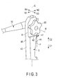
- FIG. 3 shows the exterior of the held section 3
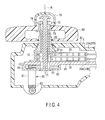
- FIGS. 4 and 5 show the internal configuration of the held section casing 8.
- an LR sprocket (a first rotating member) 31 and a UD sprocket (a second rotating member) 32 are provided (housed).
- the LR sprocket 31 and the UD sprocket 32 are rotatable about a rotational axis R which is perpendicular to the longitudinal axis C, and the LR sprocket 31 and the UD sprocket 32 are coaxial with respect to each other.
- proximal ends of a pair of LR bending wires (first linear portions) 33A and 33B are connected to the LR sprocket 31 via an LR chain 35.
- the proximal ends of a pair of UD bending wires (second linear portions) 37A and 37B are connected to the UD sprocket 32 via a UD chain 39.
- the LR bending wires 33A and 33B are extended along the longitudinal axis C inside of the inserting section 2.
- the distal ends of the LR bending wires 33A and 33B are connected to a distal portion of the bending section 6.
- the LR sprocket (the first rotating member) 31 rotates about the rotational axis R so as to pull one of the LR bending wires 33A and 33B.
- the bending section 6 is bent toward a bending Left direction (the direction indicated by the arrow L in FIG.
- the bending section 6 is bent in a bending Right direction (the direction indicated by the arrow R in FIG. 1 ).
- the bending section 6 is bent toward one of the bending LR directions, i.e., the first bending directions, when one of the LR bending wires (the first linear portions) 33A, 33B is pulled.
- the UD bending wires 37A and 37B are extended along the longitudinal axis C inside of the inserting section 2.
- the distal ends of the UD bending wires 37A and 37B are connected to the distal portion of the bending section 6.
- the UR sprocket (the second rotating member) 32 rotates about the rotational axis R so as to pull one of the UD bending wires 37A or 37B.
- the bending section 6 is bent toward a bending Up direction (the direction indicated by the arrow U in FIG. 1 ), and as the UD bending wire 37B is pulled, the bending section 6 is bent in a bending Down direction (the direction indicated by the arrow D in FIG. 1 ).
- the bending section 6 is bent toward one of the bending UD directions, i.e., the second bending directions, when one of the UD bending wires (the second linear portions) 37A, 37B is pulled.
- one of the directions perpendicular to the longitudinal axis C and the rotational axis R is defined as a first perpendicular direction (indicated by the arrow N1 in FIG. 3 ), and the direction opposite to the first perpendicular direction is defined as a second perpendicular direction (indicated by the arrow N2 in FIG. 3 ).
- a direction rotated 90 degrees from the first perpendicular direction toward a counterclockwise direction around the longitudinal axis C viewed from the proximal direction is defined as a third perpendicular direction (indicated by the arrow N3 in FIG.
- the opposite direction to the third perpendicular direction is defined as a fourth perpendicular direction (indicated by the arrow N4 in FIG. 3 ).
- the third perpendicular direction and the fourth perpendicular direction are parallel to the rotational axis R.
- the first and second perpendicular directions are parallel to the bending UD directions (the second bending directions) of the bending section 6 when the inserting section 2 is in a perfectly straight condition.
- the third and fourth perpendicular directions are parallel to the bending LR directions (the first bending directions) of the bending section 6 when the inserting section 2 is in the perfectly straight condition.
- the held section casing 8 includes a first exterior surface portion 41 facing toward the second perpendicular direction, and a second exterior surface portion 42 facing toward the third perpendicular direction.
- the held section casing 8 includes a third exterior surface portion 43 facing in the first perpendicular direction, and a fourth exterior surface portion 45 facing toward the fourth perpendicular direction.
- One end of the universal cord 10 is connected to the fourth external surface portion 45 and is extended from the fourth exterior surface portion 45 toward the first perpendicular direction.
- a LR bending operation dial (electric bending operation section) 47 is provided to the first exterior surface portion 41.
- the LR bending operation dial 47 is rotatably coupled to the held section casing 8 about the rotational axis P with respect to the held section casing 8.
- the rotational axis P of the LR bending operation dial 47 is approximately parallel to the longitudinal axis C.
- the LR bending operation dial 47 rotates to input a LR electrical bending operation (electrical bending operation) for bending the bending section 6 in the bending LR directions.
- a potentiometer 48 is provided as a detecting section inside of the held section casing 8.
- One end of an electrical signal line 51 is connected to the potentiometer 48.
- the electrical signal line 51 is extended through the inside of the held section casing 8 and the inside of the universal cord 10.
- the control unit 15 is connected to the scope connector 11 via a wiring cable 52.
- the control unit 15 includes a driving control section 53.
- the other end of the electrical signal line 51 is connected to the driving control section 53 and the electrical signal line 51 is extended from the scope connector 11 through the inside of the wiring cable 52.
- the potentiometer 48 detects a rotation of the LR bending operation dial 47 so as to detect an input of the LR electrical bending operation by the LR bending operation dial 47. Then, an electrical signal based on the detection result is sent to the driving control section 53 via the electrical signal line 51.
- An electric motor 55 as a driving member is provided inside the scope connector 11.
- the electric motor 55 is connected to the drive control unit 53 via the electric wiring 57.
- the driving control section 53 supplies an electric power to the electric motor 55 based on the detection result at the potentiometer 48.
- the electric motor 55 is driven, and an electrical driving force is generated.
- An actuating unit 60 is provided inside of the held section casing 8.
- a driving shaft 59 connects the actuating unit 60 to the electric motor 55.
- the driving shaft 59 is extended inside the universal cord 10. Upon driving the electric motor 55, an electrical driving force is transmitted to the actuating unit 60 via the driving shaft 59.
- the actuating unit 60 is actuated upon transmitting the electrical driving force.
- FIG. 6 shows the configuration of the actuating unit 60.
- a plate-shaped member 61 is fixed to the held section casing 8 inside the held section casing 8.
- a frame member 62 is fixed to the plate-like member 61.
- the actuating unit 60 includes a bevel gear 63 to which the driving shaft 59 is connected.
- the universal cord 10, in which the driving shaft 59 is internally extended, extends from the held section 3 toward the first perpendicular direction (upward direction perpendicular to the pages illustrating FIGS. 4 and 5 , i.e., the direction indicated by the arrow N1 in FIG. 6 ).
- the bevel gear 63 receives the electrical driving force from the first perpendicular direction via the driving shaft 59.
- the bevel gear 63 acts as a driving force receiving portion configured to receive the electrical driving force from the first perpendicular direction. Upon receiving the electrical driving force, the bevel gear 63 rotates.
- the actuating unit 60 includes a relay gear 65.
- the relay gear 65 is attached to the plate-shaped member 61 in a manner such that the relay gear 65 is housed inside the frame member 62.
- a pillar-shaped member 67 couples the bevel gear 63 to the relay gear 65.
- the electrical driving force is transmitted to the relay gear 65 via the pillar-like member 67, and the relay gear 65 pivots.
- the actuating unit 60 includes a spur gear 69 that engages the relay gear 65.
- the spur gear 69 is coaxial with the LR sprocket 31 and the UD sprocket 32, and is rotatable about the rotational axis R. Upon the rotation of the relay gear 69, the electrical driving force is transmitted to the spur gear 69, and the spur gear 69 pivots.
- a shaft member 71 is fixed to the frame member 62 inside the held section casing 8. Since the frame member 62 is fixed to the held section casing 8, the shaft member 71 is fixed to the held section casing 8.
- the shaft member 71 is coaxial with the LR sprocket 31 and the UD sprocket 32, and it is extended along the rotational axis R up to an outside of the held section casing 8 with penetrating the spur gear 69, the LR sprocket 31 and the UD sprocket 32. Accordingly, the spur gear 69, the LR sprocket 31, and the UD sprocket 32 are placed so as to cover an outer peripheral portion of the shaft member 71.
- a cylindrical case 72 is fixed to the plate-shaped member 61 inside the held section casing 8. Since the plate-like member 61 is fixed to the held section casing 8, the cylindrical case 72 is fixed to the held section casing 8.
- the cylindrical case 72 is extended along the rotational axis R up to the outside of the held section casing 8.
- the LR sprocket 31 and the UD sprocket 32 are housed inside the cylindrical case 72.
- a LR mantle 73 placed between the shaft member 71 and the cylindrical case 72 is extended along the rotational axis R up to the outside of the held section casing 8.
- the LR mantle 73 is attached to the LR sprocket 31 rotatably about the rotational axis R integrally with the LR sprocket (the first rotating member) 31.
- the LR toe 73 is movable with respect to the shaft member 71 and the LR sprocket 31 along the rotational axis R.
- the LR mantle 73 is a moving portion that is movable along the rotational axis R with respect to the LR sprocket 31.
- a switching pin 75 which acts as a switch operation inputting section is fixed to the LR mantle 73 at the outside of the held section casing 8.
- a groove 78 is formed in the LR toe 73.
- the switching pin 75 is inserted in the groove 78, and the groove 78 and the switching pin 75 are engaged, thereby fixing the switching pin 75 to the LR mantle 73. Since the switching pin 75 is fixed to the LR mantle 73, an input of the switching operation by the switching pin 75 causes an operation force that results from the switching operation to be transmitted from a switching pin 75 to the LR mantle 73, which is a moving portion. As a result, the LR mantle 73 moves along the rotational axis R, and the connection state of the LR mantle 73 to the spur gear 69 of the actuating unit 60 is switched.
- the switching pin 75 and the LR mantle 73 act as a connection switching section configured to switch the connection state of the LR mantle (moving portion) 73 to the actuating unit 60, and also act as a transmission switching section configured to switch the transmission state of the electrical driving force between the actuating unit 60 and the LR sprocket (the first rotating member) 31.
- the transmission state of the electrical driving force is switched to a transmittable state where an electrical driving force can be transmitted from the actuating unit 60 to the LR sprocket 31 (the state illustrated in FIG. 4 ), or to a non-transmittable state where an electrical driving force cannot be transmitted from the actuating unit 60 to the LR sprocket 31 (the state illustrated in FIG. 5 ).
- the LR mantle 73 which acts as the moving portion, moves when switching between the transmittable state and the non-transmittable state.
- the LR mantle 73 is connected to the spur gear 69 of the actuating unit 60. For this reason, the electrical driving force is transmitted to the LR mantle 73 upon the rotation of the spur gear 69, and the LR mantle 73 and the LR sprocket 31 integrally rotate about the rotational axis R.
- the LR mantle 73 in the non-transmittable state, the LR mantle 73 is not connected to the spur gear 69 of the actuating unit 60. For this reason, an electrical driving force is not transmitted to the LR mantle 73 even when the spur gear 69 rotates, and therefore, the LR mantle 73 and the LR sprocket 31 do not rotate.
- the LR sprocket (the first rotational member) 31 does not rotate by the electrical driving force.
- an LR bending operation knob (a first manual bending operation section) 77 is detachably attached to the LR mantle (moving portion) 73 via the switching pin 75.
- the LR bending operation knob 77 is attached to the LR mantle 73 at the outside of the held section casing 8, thereby coupling the LR bending operation knob 77 to the held section casing 8.
- the LR bending operation knob 77 is coaxial with the LR mantle 73 when the LR bending operation knob 77 is attached to the LR mantle 73, and the knob 77 is rotatable about the rotational axis R integral with the LR mantle 73. Furthermore, while being coupled to the LR toe 73, the LR bending operation knob 77 is placed on the second exterior surface portion 42.
- the LR bending operation knob 77 is rotated to input an LR manual bending operation (a first manual bending operation) for bending the bending section 6 in the bending LR directions. Therefore, a first manual driving force is generated, and the first manual driving force is transmitted to the LR sprocket 31 via the switching pin 75 and the LR mantle 73.
- the LR sprocket (first rotating member) 31 rotates integrally with the LR mantle (moving portion) 73.
- a cap 79 instead of the LR bending operation knob 77, is attached to the LR mantle 73.
- the cap 79 is detachably attached to the LR mantle 73 at the outside of the held section casing 8.
- a UD mantle 81 located between the LR mantle 73 and the cylindrical case 72 is extended along the rotational axis R up to the outside of the held section casing 8.
- One end of the UD mantle 81 is coupled to the UP sprocket (second rotating member) 32, and the UD toe 81 is fixed to the UD sprocket 32.
- the UD mantle 81 is rotatable about the rotational axis R integral with the UD sprocket 32.
- a UD bending operation knob (second manual bending operation section) 83 is attached to the other end of the UD mantle 81, and the UD bending operation knob 83 is coupled to the held section casing 8.
- the UD bending operation knob 83 is fixed to the UD toe 81, and is rotatable about the rotational axis R integral with the UD mantle 81 and the UD sprocket 32.
- the UD bending operation knob 83 is placed on the second exterior surface portion 42.
- the shaft member 71 and the LR mantle 73 are extended with penetrating the UD bending operation knob 83.
- a second UD manual bending operation (second manual bending operation) for bending the bending section 6 in the bending UD directions is input.
- a second manual driving force is generated, and the second manual driving force is transmitted to the UD sprocket 32 via the UD mantle 81.
- the UD sprocket (second rotating member) 32 rotates integrally with the UD mantle 81.
- the UD bending operation knob 83 When bending the bending section 6 toward one of the bending UD directions which are second bending directions, the UD bending operation knob 83 is rotated to input a UD manual bending operation (second manual bending operation).
- the second manual driving force is transmitted to the UD sprocket (second rotating member) 32 via the UD mantle 81, and the UD sprocket 32 rotates around the rotational axis R.
- the UD sprocket 32 Upon the rotation of the UD sprocket 32, one of the UD bending wires 37A or 37B is pulled, and the bending 6 is bent toward the bending Up direction or the bending Down direction.
- the endoscope 1 in a normal case where no malfunctions occur at the electric motor 55 which is a driving member, the LR mantle (moving portion) 73 is connected to the spur gear 69 of the actuating unit 60. For this reason, the endoscope 1 is then in the transmittable state where an electrical driving force from the electric motor 55 is transmitted from the actuating unit 60 to the LR sprocket (first rotating member) 31.
- the LR bending operation dial (electric bending operation section) 47 is rotated to input the LR electrical bending operation (electrical bending operation). Then, the driving control section 53 supplies electric power to the electric motor 55 based on the detection result at the potentiometer 48. Upon being supplied with electric power, the electric motor 55 is driven, and an electrical driving force is generated. Then, upon transmitting the electrical driving force to the actuating unit 60, the actuating unit 60 is actuated.
- the electrical driving force can be transmitted from the actuating unit 60 to the LR sprocket 31.
- the LR sprocket 31 rotates about the rotational axis R upon actuating the actuating unit 6.
- the LR sprocket 31 rotates, one of the LR bending wires 33A or 33B is pulled, and the bending 6 is bent toward the bending Right direction or the bending Left direction.
- the LR mantle (moving portion) 73 When any malfunctions occur at the electric motor 55, the LR mantle (moving portion) 73 is moved from the transmittable state along the rotational axis R by the switching operation at the switching pin 75. As a result, the LR mantle 73 is not connected to the spur gear 69 of the actuating unit 60, and is in the non-transmittable state where no electric moving force is transmitted from the actuating unit 60 to the LR sprocket 31. At this time, even when the LR electrical bending operation is input at the LR bending operation dial 47, and the actuating unit 60 is actuated, the LR sprocket 31 does not rotate by the electrical driving force.
- the cap 79 is removed from the LR toe 73, and the LR bending operation knob (first manual bending operation section) 77 is detachably attached to the LR mantle 73.
- the LR manual bending operation (first manual bending operation) is input.
- a manual driving force is transmitted to the LR sprocket (first rotating member) 73 via the LR mantle 73, and the LR sprocket 31 rotates about the rotational axis R.
- the LR sprocket 31 rotates, one of the LR bending wires 33A or 33B is pulled, and the bending 6 is bent toward the bending Right direction or the bending Left direction.
- the endoscope 1 is switched into the non-transmittable state where no electrical driving force is transmitted from the actuating unit 60 to the LR sprocket 31. For this reason, it is possible to eliminate the influence of malfunctions on the bend of the bending section 6.
- an LR bending operation knob 77 is attached to the LR mantle 73.
- a manual driving force is transmitted to the LR sprocket 31, and the LR sprocket 31 rotates about the rotational axis R.
- the bending 6 is bent toward one of the bending LR directions (first bending directions). Accordingly, it is possible to bend the bending section 6 appropriately without driving the electric motor 55, even when any malfunction occurs at the electric motor 55.
- the LR mantle 73 is enabled to move along the rotational axis R with respect to the LR sprocket 31, and the switching pin 75 is provided to the LR mantle 73.
- the switching of the state of transmission of the electrical driving force can be realized without making the configuration of the interior of the held section casing 8 complicated.
- the LR bending operation knob 77 is detachably attached to the movable LR mantle 73, it is possible to input the LR manual bending operation (first manual bending operation) under the non-transmittable state. In other words, it is possible to input the LR manual bending operation under the non-transmittable state without making the configuration of the held section 3 complicated.
- FIG. 7 shows the held section 3 held by an operator with their left hand.
- the palm G is touching the third exterior surface portion 43 facing toward the first perpendicular direction (indicated by the arrow N1 in FIG. 7 ).
- the index finger F2, the middle finger F3, the ring finger F4 and the little finger F5 are extended from the first perpendicular direction toward the second perpendicular direction (indicated by the arrow N2 in FIG. 7 ).
- the operator it becomes easier for the operator to hold the held section 3 by configuring the actuating unit 60 to receive an electrical driving force from the first perpendicular direction. Furthermore, it becomes easier for the operator to input the LR electrical bending operation by the LR bending operation dial 47 with the index finger F2 or the middle finger F3 while holding the held section 3 by arranging the LR bending operation dial 47 on the first exterior surface portion 41 which faces toward the second perpendicular direction. Furthermore, as the LR bending operation knob 77 and the UD bending operation knob 83 are placed on the second exterior surface portion 42 facing toward the third perpendicular direction (indicated by the arrow N3 in FIG. 7 ), it becomes easier for the operator to input the LR manual bending operation by the LR bending operation knob 77 with the thumb F1, and to input the UD manual bending operation by the UD bending operation knob 83 with the thumb, while holding the held section 3.
- connection of the LR mantle 73, which is coaxial with the rotational axis R, to the actuating unit 60 is switched in order to switch between the transmittable state and the non-transmittable state; however, the way of switching between the states is not limited thereto.
- a spur gear (not shown) may be provided to the actuating unit 60 and a gear section (not shown) provided to the LR sprocket 31, so that the engagement of the spur gear of the actuating unit 60 and the gear section of the LR sprocket 31 can be changed.
- the endoscope when the spur gear of the actuating unit 60 and the gear section of the LR sprocket 31 are engaged, the endoscope will be in the transmittable state. When the spur gear is moved from the transmittable state and the spur gear does not engage the gear section of the LR sprocket 31, the endoscope will be in the non-transmittable state.
- an electric bending operation section for inputting the LR electrical bending operation is the LR bending operation dial 47; however, it is not limited thereto.
- the electric bending operation section may be an LR bending operation lever.
- a configuration of switching the state of transmitting an electrical driving force to the LR sprocket 31 when bending the bending section 6 in the bending LR directions is described; however, such a configuration is not limited thereto.
- an electrical driving force can be generated at a driving member (not shown), and the state of transmitting the electrical driving force to the UD sprocket 32 can be switched.
- the electric motor 55 which is a driving member, is provided in the scope connector 11; however, the location to place the driving member is not limited thereto.
- an electric driving member may be detachably attached to the held section 3.
- the endoscope 1 was explained; however, the embodiment can be realized in a different device.
- the aforementioned configuration can be applied to a manipulator having an inserting section in which a bending section is provided, the bending section being bendable in the first bending directions perpendicular to the longitudinal axis and bendable in the second bending directions perpendicular to the first bending direction.
- the previously-mentioned configuration may be applied to an insertion device, such as the endoscope 1, etc.
- the actuating unit 60 which is actuated by an electrical driving force generated by a driving member (55), should be provided inside the held section casing 8. Furthermore, a transmission switching section (75) configured to switch the states of transmission of the electrical driving force from a driving member (55) between the actuating unit 60 and a first rotating member (31) should be provided. The transmission switching section (75) should switch between the non-transmittable state where no electrical driving force is transmitted from the actuating unit 60 to a first rotating member (31) and the transmittable state where the electrical driving force is transmitted from the actuating unit 60 to a first rotating member (31) to rotate the first rotating member (31).
Landscapes
- Health & Medical Sciences (AREA)
- Life Sciences & Earth Sciences (AREA)
- Engineering & Computer Science (AREA)
- Surgery (AREA)
- Heart & Thoracic Surgery (AREA)
- Biophysics (AREA)
- Veterinary Medicine (AREA)
- Public Health (AREA)
- General Health & Medical Sciences (AREA)
- Animal Behavior & Ethology (AREA)
- Biomedical Technology (AREA)
- Medical Informatics (AREA)
- Physics & Mathematics (AREA)
- Molecular Biology (AREA)
- Radiology & Medical Imaging (AREA)
- Pathology (AREA)
- Optics & Photonics (AREA)
- Nuclear Medicine, Radiotherapy & Molecular Imaging (AREA)
- General Engineering & Computer Science (AREA)
- Mechanical Engineering (AREA)
- Anesthesiology (AREA)
- Hematology (AREA)
- Pulmonology (AREA)
- Endoscopes (AREA)
- Instruments For Viewing The Inside Of Hollow Bodies (AREA)
Applications Claiming Priority (2)
| Application Number | Priority Date | Filing Date | Title |
|---|---|---|---|
| JP2013020726 | 2013-02-05 | ||
| PCT/JP2014/052625 WO2014123135A1 (ja) | 2013-02-05 | 2014-02-05 | 挿入装置 |
Publications (2)
| Publication Number | Publication Date |
|---|---|
| EP2954832A1 true EP2954832A1 (de) | 2015-12-16 |
| EP2954832A4 EP2954832A4 (de) | 2016-12-28 |
Family
ID=51299727
Family Applications (1)
| Application Number | Title | Priority Date | Filing Date |
|---|---|---|---|
| EP14749477.7A Withdrawn EP2954832A4 (de) | 2013-02-05 | 2014-02-05 | Einsetzvorrichtung |
Country Status (5)
| Country | Link |
|---|---|
| US (1) | US10194786B2 (de) |
| EP (1) | EP2954832A4 (de) |
| JP (1) | JP5702031B2 (de) |
| CN (1) | CN104736040B (de) |
| WO (1) | WO2014123135A1 (de) |
Families Citing this family (5)
| Publication number | Priority date | Publication date | Assignee | Title |
|---|---|---|---|---|
| EP3219246A4 (de) | 2014-11-12 | 2018-09-05 | Olympus Corporation | Wähleinheit und einführungsvorrichtung |
| US10426616B2 (en) * | 2016-11-17 | 2019-10-01 | Evalve, Inc. | Cardiac implant delivery system |
| KR20220050151A (ko) * | 2019-08-15 | 2022-04-22 | 아우리스 헬스, 인코포레이티드 | 다수의 굽힘 섹션을 갖는 의료 장치 |
| EP3811842B1 (de) * | 2019-10-23 | 2026-01-21 | Medizinische Universität Wien | Endoskop |
| DE102020111885A1 (de) | 2020-04-30 | 2021-11-04 | Ambu A/S | Lenkanordnung für ein Endoskop, insbesondere für ein Einwegendoskop |
Family Cites Families (16)
| Publication number | Priority date | Publication date | Assignee | Title |
|---|---|---|---|---|
| US5007406A (en) * | 1988-11-04 | 1991-04-16 | Asahi Kogaku Kogyo Kabushiki Kaisha | Bending control device of endoscope |
| JP2697880B2 (ja) * | 1988-12-15 | 1998-01-14 | オリンパス光学工業株式会社 | 内視鏡の湾曲装置 |
| JPH02164332A (ja) * | 1988-12-19 | 1990-06-25 | Olympus Optical Co Ltd | 内視鏡 |
| JP2935475B2 (ja) * | 1990-12-07 | 1999-08-16 | オリンパス光学工業株式会社 | 内視鏡装置 |
| JP3093804B2 (ja) * | 1991-02-12 | 2000-10-03 | オリンパス光学工業株式会社 | 内視鏡 |
| JPH1132977A (ja) * | 1997-07-17 | 1999-02-09 | Olympus Optical Co Ltd | 内視鏡装置 |
| JP4311994B2 (ja) * | 2002-09-30 | 2009-08-12 | オリンパス株式会社 | 電動湾曲内視鏡 |
| JP4323209B2 (ja) * | 2003-04-25 | 2009-09-02 | オリンパス株式会社 | 電動湾曲内視鏡 |
| JP4098667B2 (ja) * | 2003-05-14 | 2008-06-11 | オリンパス株式会社 | 電動湾曲内視鏡 |
| WO2006059722A1 (ja) * | 2004-12-03 | 2006-06-08 | Olympus Corporation | 挿入部着脱式湾曲内視鏡、及び挿入部着脱式電動湾曲内視鏡装置 |
| JP5209903B2 (ja) | 2007-06-18 | 2013-06-12 | オリンパスメディカルシステムズ株式会社 | 電動湾曲内視鏡用動力伝達装置 |
| US20090076330A1 (en) * | 2007-09-19 | 2009-03-19 | Fujifilm Corporation | Endoscope |
| US8409079B2 (en) * | 2008-05-14 | 2013-04-02 | Olympus Medical Systems Corp. | Electric bending operation device and medical treatment system including electric bending operation device |
| JPWO2010047223A1 (ja) | 2008-10-22 | 2012-03-22 | オリンパスメディカルシステムズ株式会社 | 手動湾曲内視鏡用駆動ユニット |
| JP2012100926A (ja) * | 2010-11-11 | 2012-05-31 | Olympus Medical Systems Corp | 体腔内挿入器具 |
| CN103179894B (zh) * | 2010-12-01 | 2015-07-29 | 奥林巴斯医疗株式会社 | 内窥镜 |
-
2014
- 2014-02-05 EP EP14749477.7A patent/EP2954832A4/de not_active Withdrawn
- 2014-02-05 WO PCT/JP2014/052625 patent/WO2014123135A1/ja not_active Ceased
- 2014-02-05 JP JP2014541242A patent/JP5702031B2/ja active Active
- 2014-02-05 CN CN201480002680.9A patent/CN104736040B/zh active Active
- 2014-09-08 US US14/479,810 patent/US10194786B2/en active Active
Also Published As
| Publication number | Publication date |
|---|---|
| EP2954832A4 (de) | 2016-12-28 |
| CN104736040A (zh) | 2015-06-24 |
| US10194786B2 (en) | 2019-02-05 |
| CN104736040B (zh) | 2018-05-29 |
| US20150045621A1 (en) | 2015-02-12 |
| WO2014123135A1 (ja) | 2014-08-14 |
| JPWO2014123135A1 (ja) | 2017-02-02 |
| JP5702031B2 (ja) | 2015-04-15 |
Similar Documents
| Publication | Publication Date | Title |
|---|---|---|
| US10149604B2 (en) | Endoscope having a biopsy needle with needle elevation mechanism | |
| CN104955375B (zh) | 操纵器 | |
| EP1913862A1 (de) | Endoskop | |
| CN103517664B (zh) | 内窥镜 | |
| EP2868252A1 (de) | Endoskop | |
| US10194786B2 (en) | Insertion device | |
| US20160353975A1 (en) | Bending operation mechanism for endoscope | |
| US9622648B2 (en) | Insertion device | |
| JP2002078675A (ja) | 電動アングル式電子内視鏡装置 | |
| WO2014203673A1 (ja) | 導入装置 | |
| US9259141B2 (en) | Endoscope | |
| CN100496376C (zh) | 内窥镜 | |
| US20150313447A1 (en) | Insertion instrument and endoscope | |
| CN108135451B (zh) | 插入装置 | |
| EP2862498A1 (de) | Endoskopbetriebseinheitsstruktur | |
| EP2832282A1 (de) | Einsetzvorrichtung, rotierendes rohrförmiges element und antriebseinheit | |
| JP2014223293A (ja) | 導入装置 | |
| EP3656281B1 (de) | Endoskop | |
| US10299659B2 (en) | Insertion instrument and insertion device | |
| CN107072477B (zh) | 插入装置 | |
| CN112074222B (zh) | 内窥镜的驱动力传递机构和内窥镜 | |
| US20230084433A1 (en) | Endoscope | |
| JPH0595896A (ja) | 内視鏡 | |
| US20160174815A1 (en) | Introduction device | |
| JP2008228953A (ja) | 内視鏡 |
Legal Events
| Date | Code | Title | Description |
|---|---|---|---|
| PUAI | Public reference made under article 153(3) epc to a published international application that has entered the european phase |
Free format text: ORIGINAL CODE: 0009012 |
|
| 17P | Request for examination filed |
Effective date: 20150819 |
|
| AK | Designated contracting states |
Kind code of ref document: A1 Designated state(s): AL AT BE BG CH CY CZ DE DK EE ES FI FR GB GR HR HU IE IS IT LI LT LU LV MC MK MT NL NO PL PT RO RS SE SI SK SM TR |
|
| AX | Request for extension of the european patent |
Extension state: BA ME |
|
| DAX | Request for extension of the european patent (deleted) | ||
| RAP1 | Party data changed (applicant data changed or rights of an application transferred) |
Owner name: OLYMPUS CORPORATION |
|
| RAP1 | Party data changed (applicant data changed or rights of an application transferred) |
Owner name: OLYMPUS CORPORATION |
|
| RIN1 | Information on inventor provided before grant (corrected) |
Inventor name: MASAKI, YUTAKA |
|
| A4 | Supplementary search report drawn up and despatched |
Effective date: 20161128 |
|
| RIC1 | Information provided on ipc code assigned before grant |
Ipc: A61B 1/00 20060101AFI20161122BHEP Ipc: A61M 25/01 20060101ALI20161122BHEP Ipc: F16D 11/00 20060101ALI20161122BHEP Ipc: A61B 1/005 20060101ALI20161122BHEP |
|
| STAA | Information on the status of an ep patent application or granted ep patent |
Free format text: STATUS: REQUEST FOR EXAMINATION WAS MADE |
|
| STAA | Information on the status of an ep patent application or granted ep patent |
Free format text: STATUS: THE APPLICATION IS DEEMED TO BE WITHDRAWN |
|
| 18D | Application deemed to be withdrawn |
Effective date: 20180901 |