EP2954844B1 - Joint rotatif sans contact - Google Patents
Joint rotatif sans contact Download PDFInfo
- Publication number
- EP2954844B1 EP2954844B1 EP15169494.0A EP15169494A EP2954844B1 EP 2954844 B1 EP2954844 B1 EP 2954844B1 EP 15169494 A EP15169494 A EP 15169494A EP 2954844 B1 EP2954844 B1 EP 2954844B1
- Authority
- EP
- European Patent Office
- Prior art keywords
- rotary joint
- shield
- contactless
- rotating transformer
- joint body
- Prior art date
- Legal status (The legal status is an assumption and is not a legal conclusion. Google has not performed a legal analysis and makes no representation as to the accuracy of the status listed.)
- Active
Links
Images


Classifications
-
- H—ELECTRICITY
- H02—GENERATION; CONVERSION OR DISTRIBUTION OF ELECTRIC POWER
- H02J—ELECTRIC POWER NETWORKS; CIRCUIT ARRANGEMENTS OR SYSTEMS FOR SUPPLYING OR DISTRIBUTING ELECTRIC POWER; SYSTEMS FOR STORING ELECTRIC ENERGY
- H02J50/00—Circuit arrangements or systems for wireless supply or distribution of electric power
- H02J50/70—Circuit arrangements or systems for wireless supply or distribution of electric power involving the reduction of electric, magnetic or electromagnetic leakage fields
-
- A—HUMAN NECESSITIES
- A61—MEDICAL OR VETERINARY SCIENCE; HYGIENE
- A61B—DIAGNOSIS; SURGERY; IDENTIFICATION
- A61B6/00—Apparatus or devices for radiation diagnosis; Apparatus or devices for radiation diagnosis combined with radiation therapy equipment
- A61B6/44—Constructional features of apparatus for radiation diagnosis
- A61B6/4488—Means for cooling
-
- A—HUMAN NECESSITIES
- A61—MEDICAL OR VETERINARY SCIENCE; HYGIENE
- A61B—DIAGNOSIS; SURGERY; IDENTIFICATION
- A61B6/00—Apparatus or devices for radiation diagnosis; Apparatus or devices for radiation diagnosis combined with radiation therapy equipment
- A61B6/56—Details of data transmission or power supply, e.g. use of slip rings
-
- H—ELECTRICITY
- H01—ELECTRIC ELEMENTS
- H01F—MAGNETS; INDUCTANCES; TRANSFORMERS; SELECTION OF MATERIALS FOR THEIR MAGNETIC PROPERTIES
- H01F38/00—Adaptations of transformers or inductances for specific applications or functions
- H01F38/14—Inductive couplings
-
- H—ELECTRICITY
- H01—ELECTRIC ELEMENTS
- H01F—MAGNETS; INDUCTANCES; TRANSFORMERS; SELECTION OF MATERIALS FOR THEIR MAGNETIC PROPERTIES
- H01F38/00—Adaptations of transformers or inductances for specific applications or functions
- H01F38/18—Rotary transformers
-
- H—ELECTRICITY
- H02—GENERATION; CONVERSION OR DISTRIBUTION OF ELECTRIC POWER
- H02J—ELECTRIC POWER NETWORKS; CIRCUIT ARRANGEMENTS OR SYSTEMS FOR SUPPLYING OR DISTRIBUTING ELECTRIC POWER; SYSTEMS FOR STORING ELECTRIC ENERGY
- H02J50/00—Circuit arrangements or systems for wireless supply or distribution of electric power
- H02J50/10—Circuit arrangements or systems for wireless supply or distribution of electric power using inductive coupling
-
- H—ELECTRICITY
- H04—ELECTRIC COMMUNICATION TECHNIQUE
- H04B—TRANSMISSION
- H04B5/00—Near-field transmission systems, e.g. inductive or capacitive transmission systems
- H04B5/70—Near-field transmission systems, e.g. inductive or capacitive transmission systems specially adapted for specific purposes
- H04B5/79—Near-field transmission systems, e.g. inductive or capacitive transmission systems specially adapted for specific purposes for data transfer in combination with power transfer
-
- H—ELECTRICITY
- H05—ELECTRIC TECHNIQUES NOT OTHERWISE PROVIDED FOR
- H05K—PRINTED CIRCUITS; CASINGS OR CONSTRUCTIONAL DETAILS OF ELECTRIC APPARATUS; MANUFACTURE OF ASSEMBLAGES OF ELECTRICAL COMPONENTS
- H05K9/00—Screening of apparatus or components against electric or magnetic fields
-
- H—ELECTRICITY
- H02—GENERATION; CONVERSION OR DISTRIBUTION OF ELECTRIC POWER
- H02J—ELECTRIC POWER NETWORKS; CIRCUIT ARRANGEMENTS OR SYSTEMS FOR SUPPLYING OR DISTRIBUTING ELECTRIC POWER; SYSTEMS FOR STORING ELECTRIC ENERGY
- H02J2105/00—Networks for supplying or distributing electric power characterised by their spatial reach or by the load
- H02J2105/40—Networks for supplying or distributing electric power characterised by their spatial reach or by the load characterised by the loads connecting to the networks or being supplied by the networks
- H02J2105/46—Medical devices, medical implants or life supporting devices
-
- H—ELECTRICITY
- H04—ELECTRIC COMMUNICATION TECHNIQUE
- H04B—TRANSMISSION
- H04B5/00—Near-field transmission systems, e.g. inductive or capacitive transmission systems
- H04B5/20—Near-field transmission systems, e.g. inductive or capacitive transmission systems characterised by the transmission technique; characterised by the transmission medium
- H04B5/22—Capacitive coupling
-
- H—ELECTRICITY
- H04—ELECTRIC COMMUNICATION TECHNIQUE
- H04B—TRANSMISSION
- H04B5/00—Near-field transmission systems, e.g. inductive or capacitive transmission systems
- H04B5/20—Near-field transmission systems, e.g. inductive or capacitive transmission systems characterised by the transmission technique; characterised by the transmission medium
- H04B5/24—Inductive coupling
- H04B5/26—Inductive coupling using coils
- H04B5/263—Multiple coils at either side
-
- H—ELECTRICITY
- H04—ELECTRIC COMMUNICATION TECHNIQUE
- H04B—TRANSMISSION
- H04B5/00—Near-field transmission systems, e.g. inductive or capacitive transmission systems
- H04B5/20—Near-field transmission systems, e.g. inductive or capacitive transmission systems characterised by the transmission technique; characterised by the transmission medium
- H04B5/24—Inductive coupling
- H04B5/26—Inductive coupling using coils
- H04B5/266—One coil at each side, e.g. with primary and secondary coils
Definitions
- the invention relates to contactless rotary joints.
- Such contactless rotary joints may be used in CT scanners.
- these contactless rotary joints have at least one inductive power coupler for transferring high power levels and a high-speed data link for broadband transmission of data.
- a contactless rotary joint with an inductive power coupler and a bidirectional high-speed data link is disclosed in the US patent US 7,717,619 B2 .
- Such a rotary joint is able to transfer power of more than hundred kilowatts and data in the 10 Gbit/s range.
- Due to the high power level coupled by the inductive power coupler which is based on a rotating transformer there may be interference to the data link.
- Such interference may lead to data loss or even to a complete failure of the data link.
- the magnetic cores of the rotating transformer are E-shaped and have differential windings. With further increasing power requirements and increasing data rates the risk of interference increases.
- US 2008/049904 A1 discloses a gantry for an x-ray device, which has a shield for reduction of electromagnetic interference between a transmitter for a non-contact power and a signal link.
- the problem to be solved by the invention is to improve contactless rotary joints by further minimizing the risk of interference even when the power level in the rotating transformer and the bandwidth of the data link increases.
- a further object of the invention is to reduce coupling between a rotating transformer and a contactless data link.
- Another object of the invention is to provide measures which may be implemented on a non-metal rotary joint body.
- Rotating transformers produce electric and magnetic stray fields.
- One of the objects for designing a rotating transformer is to keep the magnetic field flux within pre-determined areas.
- soft magnetic cores like specific ferrite or iron cores are used.
- a rotating transformer has a gap between the rotating parts thus allowing rotation.
- the gap is comparatively broad as the rotating part of the gantry is comparatively heavy.
- the gantry may even be tilted and therefore requires additional space for mechanical movement between the rotating and stationary part, leading to a gap in the range of about 1 mm. This gap and limited magnetic conductivity of the magnetic cores leads to a magnetic stray field.
- a rotating transformer In addition to the magnetic fields a rotating transformer also generates strong electric fields.
- the windings of the rotating transformer carry significant voltages and currents.
- the voltages may be in an order of magnitude of 500 Volts.
- One means of reducing interference is keeping distance between the interfering parts.
- Basis of the invention is the diversion of electric and magnetic fields and the voltages and currents generated thereby.
- contactless rotary joints have a rotary joint body which carries the components which are necessary for transferring electrical signals or power.
- the rotary joint body may be made of metal which gives a high mechanical stability and provides for some shielding between the individual components.
- the drawback is the close electrical coupling between the components attached thereto which again increases interference.
- metal structures are generally radiating high-frequency signals as they are transmitted by the capacitive data link transmission lines.
- rotary joint systems comprise of the first rotary joint body and second rotary joint body mounted rotatable in close proximity to each other. In general they are very similar and almost symmetrically to each other. In most cases there is a capacitive data link comprising of a transmission line and a transmitter and an inductive transformer comprising of a transformer magnetic core with windings attached to a rotary joint body.
- At least one shielding is provided.
- the shielding preferably reduces interference from the rotating transformer.
- Such a shielding is preferably a conducting backplane mounted to a side of the rotary joint body opposing the rotating transformer magnetic core.
- an inner shield within the rotary joint body located between the rotating transformer magnetic core and the capacitive data link transmission line.
- This shield may be molded into the rotary joint body.
- a further preferred embodiment relates to a core shield which at least partially encloses the rotating transformer magnetic core.
- At least one shield has a higher thermal conductivity than the rotary joint body. Therefore it helps dissipating heat from the rotating transformer.
- Preferably at least one shield is thermally connected to the rotating transformer core.
- at least one fin is provided, which is thermally connected to the shield.
- the backplane comprises of a material with soft magnetic properties for an improved shielding of magnetic fields.
- the transmission line may have multiple segments for transmission of data.
- At least one winding may have multiple segments.
- a shielded temperature sensor may be provided.
- This temperature sensor has a sensor shield which is electrically connected to the shield and preferably to the backplane. Furthermore the sensor is thermally coupled to at least one of magnetic core or winding.
- a metal tape is mounted to the rotary joint body.
- the metal tape has openings, preferably slits or holes. These openings may be optically or magnetically detected for identifying the position of the tape and therefore the position of the rotary joint body.
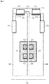
- a basic contactless rotary joint is shown. It comprises of a primary part and a secondary part which are rotatable against each other around the rotation axis 101. Basically the primary part and the secondary part are very similar.
- the primary part has a rotary joint body 100 which carries the other rotary joint components.
- the rotary joint body is a disk shaped. It may also be drum shaped. In most cases there is a free inner bore. This is specifically required in computer tomography (CT) scanners for accommodating the patient.
- CT computer tomography
- One of the components attached to or incorporated into the body is a contactless data link which is shown as a capacitive data link transmission line 110 in this embodiment. It is connected to a data transmitter 111 by connecting line 112.
- Data link transmission line 110 is almost encircling the rotary joint body 100, thus allowing data transmission independent of rotation angle.
- Data link receiver 213 is located at a predetermined position and not encircling the body. It is mounted rotatable in close proximity of the transmission line to pick up signals emitted from of the transmission line. It is attached to the secondary side by means of a second bracket 214. Therefore data link receiver 213 moves against data link transmission line 110 during rotation.
- This contactless data link may communicate data from the primary part to the secondary part.
- a rotating transformer is provided for transmission of power a rotating transformer is provided. It comprises of a magnetic core 120. In this embodiment it is an E-shaped core having a forward winding 121 and a backward winding 122. Preferably the windings are made of litz wire.
- the magnetic core may comprise a plurality of individual core segments.
- a secondary part Opposed to the primary part is a secondary part which has a secondary rotary joint body 200. It further comprises a second capacitive data link with a transmission line 210 fed via second connecting line 212 by second data transmitter 211. The second capacitive data link is able to transfer data from the secondary part to the primary part. It also has a data receiver 113 which is mounted by bracket 114 to rotary joint body 100. In this embodiment a capacitive data link is shown for each direction. It is obvious that there may be only one data link for only one direction. In general in CT scanners at least one data link from rotating to stationary part is required. Furthermore a second rotating transformer is provided having a second rotating transformer magnetic core 220 and a second forward winding 221 as well as a second backward winding 222.
- the rotating transformer cores of the primary side 120 and the secondary side 220 are mounted in close proximity to allow coupling of their magnetic fields. It can be seen that the primary side having rotary joint body 100 and secondary side heading rotary joint body 200 are symmetric and almost identical. Therefore in a further embodiment reference is made only to rotary joint body 100 and the parts attached thereto. It is obvious for someone skilled in the art to make the second part symmetrical to the first one.
- Rotary joint body is preferably made of a plastic material providing isolation to the components mounted thereon or therein.
- This rotary joint body may also be made of metal providing electric shielding and good heat dissipation.
- the main disadvantage of a metal rotary joint body is the comparatively high costs.
- a metal rotary joint body tends to radiate RF signals from the transmission line 110 as it is connected to the ground of this transmission line. Isolation between the transmission line and a metal rotary joint body 110 would be very complex as it requires a comparatively low capacity.
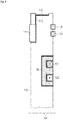
- FIG 2 another embodiment of claim 1, but not of claim 14 is shown.
- an additional first slip ring track 131 and a second slipring track 132 are provided for transferring auxiliary signals or standby power. They may further be used for grounding.
- the slipring tracks may be connected to at least one of the metal planes, structures or shield shown herein.
- the corresponding secondary side rotary joint body would not have further slipring tracks but slipring brushes to interface with these tracks.
- slipring tracks on the secondary side and corresponding brushes on the primary side may be slipring tracks on the secondary side and corresponding brushes on the primary side.
- a further embodiment having a conducting backplane 140 is shown which is preferably a metal plate or foil but may be any other electrically conducting material, acting as a shield.
- the metal structure acts as a reference plane for the field of the windings contained within magnetic core 120. It acts as a shield for the electric stray fields and parts of the magnetic stray fields of the magnetic core.
- the conducting backplane 140 is electrically connected to a magnetic core 120 there is a current between them.
- the conducting backplane may also improve heat dissipation of the rotating transformer. For this purpose it has higher heat conductivity than the rotary joint body. It may further comprise at least one fin 151 to improve heat transfer and heat dissipation to the environment. It is also preferred, if the backplane has at least one heat conductor 152 to the rotating transformer for improving heat transfer. There may also be a heat conducting material between the inductive transformer and the backplane. Furthermore it is preferred if this heat conducting material is an isolator. It is further preferred, if the distance between the rotating transformer magnetic core 120 and the backplane 140 is minimized, preferably below 5 mm to improve heat transfer. Furthermore there may be guiding structures within the rotary joint body or the backplane to generate an additional airflow to the rotating transformer magnetic core 120.
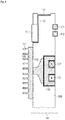
- an embodiment having an inner shield 141 is shown.
- This inner shield 141 prevents interfering of fields generated from the rotating transformer with the capacitive data link.
- the inner shield 141 has a closed ring shaped structure. It furthermore is connected to the system ground. It preferably comprises of a soft magnetic material to improve shielding. It may comprise a metal sheet, a mesh or a foil. It may preferably be casted or molded into the rotary joint body 100.
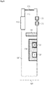
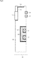
- Figure 6 shows an embodiment with the magnetic core shield 142.
- the core shield preferably surrounds magnetic core 120. It completely encloses the free sides of the magnetic core it offers the best possible shielding.
- FIG 7 an electric shield connection is shown.
- the wire of a winding 123 which may be any one of forward winding 121 or backward winding 122 is within rotating transformer magnetic core 120. It is connected to a shielded cable 150 by cable connection 145.
- the shield of shielded cable 150 is connected to shield 143 which may be any of the shields disclosed herein by a low impedance and/or low resistance connection 144.
- the connections may be crimping, soldering or welding connections.
Landscapes
- Engineering & Computer Science (AREA)
- Life Sciences & Earth Sciences (AREA)
- Health & Medical Sciences (AREA)
- Power Engineering (AREA)
- Medical Informatics (AREA)
- Computer Networks & Wireless Communication (AREA)
- Physics & Mathematics (AREA)
- Surgery (AREA)
- Public Health (AREA)
- Optics & Photonics (AREA)
- Pathology (AREA)
- Radiology & Medical Imaging (AREA)
- Biomedical Technology (AREA)
- Heart & Thoracic Surgery (AREA)
- Molecular Biology (AREA)
- Biophysics (AREA)
- Animal Behavior & Ethology (AREA)
- General Health & Medical Sciences (AREA)
- Nuclear Medicine, Radiotherapy & Molecular Imaging (AREA)
- Veterinary Medicine (AREA)
- High Energy & Nuclear Physics (AREA)
- Electromagnetism (AREA)
- Signal Processing (AREA)
- Microelectronics & Electronic Packaging (AREA)
- Shielding Devices Or Components To Electric Or Magnetic Fields (AREA)
- Measurement Of Length, Angles, Or The Like Using Electric Or Magnetic Means (AREA)
- Apparatus For Radiation Diagnosis (AREA)
- Near-Field Transmission Systems (AREA)
Claims (14)
- Articulation tournante possédant une partie fixe et une partie rotative, au moins l'une des parties comprenant un corps d'articulation tournante (100) fait d'une matière plastique, ayant au moins une gorge de bague collectrice (131, 132),
le corps d'articulation tournante tenant une liaison de données capacitive, la liaison de données capacitive possédant une ligne de transmission de données (110) pour la transmission de données sans contact, et
le corps d'articulation tournante tenant un noyau magnétique de transformateur rotatif (120) pour la transmission sans contact de puissance électrique,
ledit noyau magnétique de transformateur rotatif (120) possédant au moins un enroulement (121, 122),
caractérisée en ce que
ladite au moins une partie possède un blindage (141) prévu pour blinder des champs électriques et/ou magnétiques produits par le transformateur rotatif, afin de réduire les interférences avec la liaison de données capacitive, et
en ce que ladite au moins une partie possède au moins une gorge de bague collectrice (131, 132) utilisée pour une mise à la terre en étant connectée au blindage. - Articulation tournante sans contact selon la revendication 1,
caractérisée en ce que
le corps d'articulation tournante (100) est en forme de disque et le noyau magnétique de transformateur rotatif (120) est tenu d'un côté du disque, tandis qu'un fond de panier conducteur est monté sur le côté opposé du disque. - Articulation tournante sans contact selon l'une quelconque des revendications précédentes,
caractérisée en ce que
un blindage interne (143) est moulé dans le corps d'articulation tournante (100). - Articulation tournante sans contact selon l'une quelconque des revendications précédentes,
caractérisée en ce que
un blindage de noyau (142) renferme au moins partiellement le noyau magnétique de transformateur rotatif (120) . - Articulation tournante sans contact selon l'une quelconque des revendications précédentes,
caractérisée en ce que
au moins un blindage (140, 141, 142, 143) possède une plus grande conductivité thermique que le corps d'articulation tournante (100). - Articulation tournante sans contact selon la revendication 5,
caractérisée en ce que
au moins un blindage (140, 141, 142, 143) est raccordé thermiquement avec le noyau de transformateur rotatif (120) . - Articulation tournante sans contact selon la revendication 5,
caractérisée en ce que
au moins un blindage (140, 141, 142, 143) possède au moins une ailette (151) pour augmenter la dissipation de chaleur vers l'environnement. - Articulation tournante sans contact selon l'une quelconque des revendications précédentes,
caractérisée en ce que
le transformateur rotatif a au moins un enroulement (123) qui est connecté à un onduleur par un câble blindé (150), le blindage du câble étant connecté à l'au moins un blindage (140, 141, 142, 143) et le conducteur interne étant connecté à l'au moins un enroulement. - Articulation tournante sans contact selon l'une quelconque des revendications 1 à 8,
caractérisée en ce que
le fond de panier comprend un matériau ayant des propriétés d'aimantation temporaire. - Articulation tournante sans contact selon l'une quelconque des revendications précédentes,
caractérisée en ce que
la ligne de transmission (110) possède plusieurs segments pour la transmission de données. - Articulation tournante sans contact selon l'une quelconque des revendications précédentes,
caractérisée en ce que
au moins un enroulement (121, 122) possède plusieurs segments. - Articulation tournante sans contact selon l'une quelconque des revendications précédentes,
caractérisée en ce que
un capteur de température blindé possédant un blindage connecté électriquement au fond de panier et le capteur est couplé thermiquement avec au moins soit le noyau magnétique (120), soit l'enroulement (121, 122). - Articulation tournante sans contact selon l'une quelconque des revendications précédentes,
caractérisée en ce que
un ruban métallique est monté sur le corps d'articulation tournante et possède des ouvertures pour la lecture optique ou magnétique de la position du ruban et ainsi de la position du corps d'articulation tournante. - Articulation tournante sans contact pour un tomodensitomètre possédant une partie fixe et une partie rotative, la partie rotative, au minimum, comprenant : un corps d'articulation tournante (200) fait d'une matière plastique, lequel corps possède un alésage interne libre de préférence pour accueillir un patient, contenant une liaison de données capacitive avec une ligne de transmission de données (110), pour la transmission sans contact de données, et contenant un transformateur rotatif qui possède un noyau magnétique de transformateur rotatif (220), pour la transmission sans contact de puissance électrique, qui possède au moins un enroulement (221, 222) ;
l'articulation tournante étant caractérisée en ce qu'au moins un blindage (141, 142) est prévu pour blinder des champs électriques et/ou magnétiques produits par le transformateur rotatif, afin de réduire les interférences avec la liaison de données capacitive, et en ce qu'au moins un blindage a une plus grande conductivité thermique que le corps d'articulation tournante (200) et est adapté pour aider à dissiper la chaleur du transformateur rotatif, ledit blindage étant raccordé thermiquement avec le noyau de transformateur rotatif.
Applications Claiming Priority (3)
| Application Number | Priority Date | Filing Date | Title |
|---|---|---|---|
| DE102010041573 | 2010-09-28 | ||
| PCT/EP2011/062529 WO2012041554A1 (fr) | 2010-09-28 | 2011-07-21 | Articulation rotoïde sans contact |
| EP11749363.5A EP2621341B1 (fr) | 2010-09-28 | 2011-07-21 | Joint rotatif sans contact |
Related Parent Applications (2)
| Application Number | Title | Priority Date | Filing Date |
|---|---|---|---|
| EP11749363.5A Division-Into EP2621341B1 (fr) | 2010-09-28 | 2011-07-21 | Joint rotatif sans contact |
| EP11749363.5A Division EP2621341B1 (fr) | 2010-09-28 | 2011-07-21 | Joint rotatif sans contact |
Publications (2)
| Publication Number | Publication Date |
|---|---|
| EP2954844A1 EP2954844A1 (fr) | 2015-12-16 |
| EP2954844B1 true EP2954844B1 (fr) | 2020-08-26 |
Family
ID=44532799
Family Applications (2)
| Application Number | Title | Priority Date | Filing Date |
|---|---|---|---|
| EP11749363.5A Revoked EP2621341B1 (fr) | 2010-09-28 | 2011-07-21 | Joint rotatif sans contact |
| EP15169494.0A Active EP2954844B1 (fr) | 2010-09-28 | 2011-07-21 | Joint rotatif sans contact |
Family Applications Before (1)
| Application Number | Title | Priority Date | Filing Date |
|---|---|---|---|
| EP11749363.5A Revoked EP2621341B1 (fr) | 2010-09-28 | 2011-07-21 | Joint rotatif sans contact |
Country Status (4)
| Country | Link |
|---|---|
| US (2) | US9362047B2 (fr) |
| EP (2) | EP2621341B1 (fr) |
| CN (1) | CN103260517B (fr) |
| WO (1) | WO2012041554A1 (fr) |
Families Citing this family (27)
| Publication number | Priority date | Publication date | Assignee | Title |
|---|---|---|---|---|
| JP5913947B2 (ja) * | 2011-12-09 | 2016-05-11 | 株式会社日立メディコ | X線ct装置 |
| DE102013206826C5 (de) | 2013-04-16 | 2018-03-29 | Siemens Healthcare Gmbh | Vorrichtung zur kontaktlosen Daten- und Leistungsübertragung bei einer Computertomographieanlage |
| JP6430704B2 (ja) * | 2014-02-13 | 2018-11-28 | 株式会社ExH | 電力供給システム |
| US9413049B2 (en) | 2014-03-24 | 2016-08-09 | Raytheon Company | Rotary joint including first and second annular parts defining annular waveguides configured to rotate about an axis of rotation |
| EP3035483B1 (fr) * | 2014-12-18 | 2018-04-25 | Schleifring GmbH | Joint rotatif inductif avec des noyaux de ferrite en forme de U |
| EP3034001B1 (fr) * | 2014-12-18 | 2017-10-18 | Schleifring und Apparatebau GmbH | Joint rotatif inductif avec circuit de sécurité secondaire |
| EP3035350B1 (fr) * | 2014-12-18 | 2017-03-22 | Schleifring und Apparatebau GmbH | Joint rotatif inductif |
| DE102015100233B9 (de) | 2015-01-09 | 2016-03-24 | Carl Mahr Holding Gmbh | Induktiver Drehübertrager |
| EP3046267A1 (fr) | 2015-01-15 | 2016-07-20 | Schleifring und Apparatebau GmbH | Coupleur de réception pour liaisons de données sans contact |
| DE102015121432A1 (de) * | 2015-12-09 | 2017-06-14 | Sick Ag | Vorrichtung zur kontaktlosen Übertragung von Daten und zur Ermittlung einer Winkeländerung zwischen zwei sich relativ zueinander bewegenden Gegenständen |
| US9912113B2 (en) | 2016-02-17 | 2018-03-06 | Morpho Detection, Llc | Systems and methods for implementing an electrical rotary joint in a large-diameter system using small-diameter capsule slip rings |
| CN105679522B (zh) * | 2016-03-03 | 2017-07-18 | 南京航空航天大学 | 机械和非接触复合式滑环及工作方式 |
| EP3544034B1 (fr) * | 2016-11-15 | 2023-09-27 | FUJI Corporation | Unité de connexion d'alimentation électrique sans contact, dispositif d'alimentation électrique sans contact et machine d'exploitation |
| JP6597576B2 (ja) * | 2016-12-08 | 2019-10-30 | 株式会社村田製作所 | インダクタ、および、dc−dcコンバータ |
| AU2018240288B2 (en) | 2017-03-24 | 2023-12-07 | Smiths Detection Germany Gmbh | Contactless data communication in CT systems |
| DE102017109499A1 (de) * | 2017-05-03 | 2018-11-08 | Valeo Siemens Eautomotive Germany Gmbh | Inverter |
| US10433808B2 (en) * | 2017-05-22 | 2019-10-08 | Schleifring Gmbh | Rotary joint having a capacitive data link with modular support |
| EP3449833B1 (fr) | 2017-08-29 | 2019-09-25 | Schleifring GmbH | Module de joint rotatif séparable ayant une liaison de données sans contact |
| US10636612B2 (en) * | 2018-09-28 | 2020-04-28 | Varex Imaging Corporation | Magnetic assist assembly having heat dissipation |
| CN114128036B (zh) * | 2019-05-28 | 2023-06-09 | 莫戈公司 | 分级频率响应非接触式滑环探针 |
| WO2021094576A1 (fr) | 2019-11-14 | 2021-05-20 | Schleifring Gmbh | Joint rotatif intégré compact doté d'un blindage résonant |
| RU2725156C1 (ru) * | 2019-11-26 | 2020-06-30 | Самсунг Электроникс Ко., Лтд. | Вращающееся сочленение с бесконтактной передачей данных |
| WO2021107602A1 (fr) | 2019-11-26 | 2021-06-03 | 삼성전자 주식회사 | Élément de transmission de données de type rotatif et dispositif électronique comprenant celui-ci |
| US11689344B2 (en) | 2020-05-11 | 2023-06-27 | Analog Devices International Unlimited Company | Full-duplex wireless data transfer for rotary joints |
| DE102020215568B3 (de) * | 2020-12-09 | 2022-05-12 | Siemens Healthcare Gmbh | EMV-Abschirmung für kontaktlose Datenübertragung |
| US12548920B2 (en) | 2022-05-04 | 2026-02-10 | Analog Devices International Unlimited Company | Semi-closed wireless data transfer for rotary joints |
| CN115084961B (zh) * | 2022-08-19 | 2023-03-31 | 深圳皓影医疗科技有限公司 | 一种多通道信号和能量的传输装置 |
Citations (9)
| Publication number | Priority date | Publication date | Assignee | Title |
|---|---|---|---|---|
| DE8429531U1 (de) | 1984-10-08 | 1986-04-10 | Siemens AG, 1000 Berlin und 8000 München | Computertomograph |
| US4916718A (en) | 1988-11-23 | 1990-04-10 | Picker International, Inc. | Precision scan position resolver for CT scanners |
| US5530423A (en) | 1994-09-16 | 1996-06-25 | General Electric Company | Transmission line with a grounding brush for high data rate communication in a computerized tomography system |
| DE102004035603A1 (de) | 2004-07-22 | 2006-03-16 | Siemens Ag | Gantry für eine Röntgeneinrichtung |
| US20070035883A1 (en) | 2005-08-15 | 2007-02-15 | General Electric Company | Methods and apparatus for communicating signals between portions of an apparatus in relative movement to one another |
| WO2009033573A1 (fr) | 2007-09-10 | 2009-03-19 | Sew-Eurodrive Gmbh & Co. Kg | Dispositif de couplage |
| DE102009003346A1 (de) | 2008-01-18 | 2009-07-23 | General Electric Co. | Kontaktloses Strom- und Datenübertragungsgerät |
| US20100148505A1 (en) | 2008-12-16 | 2010-06-17 | Dunlap Gregory M | Contact-less power and signal transmission device for a high power level transformer |
| DE102004051170B4 (de) | 2004-10-20 | 2015-03-05 | Siemens Aktiengesellschaft | Computertomographiegerät mit gleichzeitiger kontaktloser elektrischer Übertragung von Versorgungsspannung und Mess- und Steuerdaten |
Family Cites Families (8)
| Publication number | Priority date | Publication date | Assignee | Title |
|---|---|---|---|---|
| US5814900A (en) | 1991-07-30 | 1998-09-29 | Ulrich Schwan | Device for combined transmission of energy and electric signals |
| US5577026A (en) * | 1993-12-28 | 1996-11-19 | Analogic Corporation | Apparatus for transferring data to and from a moving device |
| US6327327B1 (en) * | 1999-09-27 | 2001-12-04 | Picker International, Inc. | Multi-channel segmented slip ring |
| DE10023592A1 (de) | 2000-05-13 | 2001-11-29 | Bosch Gmbh Robert | Induktiver Übertrager bestehend aus zwei Spulen mit je einem Kern |
| US6472791B1 (en) * | 2000-06-30 | 2002-10-29 | General Electric Copmay | Envelope for slip-ring contacting members in high-power rotary current collector system |
| US8350655B2 (en) * | 2003-02-26 | 2013-01-08 | Analogic Corporation | Shielded power coupling device |
| US7079619B2 (en) * | 2003-12-17 | 2006-07-18 | Ge Medical Systems Global Technology Company, Llc. | System and method for data slipring connection |
| US7254034B2 (en) | 2004-12-15 | 2007-08-07 | Lucent Technologies Inc. | Thermal management for shielded circuit packs |
-
2011
- 2011-07-21 EP EP11749363.5A patent/EP2621341B1/fr not_active Revoked
- 2011-07-21 CN CN201180047173.3A patent/CN103260517B/zh active Active
- 2011-07-21 EP EP15169494.0A patent/EP2954844B1/fr active Active
- 2011-07-21 WO PCT/EP2011/062529 patent/WO2012041554A1/fr not_active Ceased
-
2013
- 2013-03-27 US US13/851,306 patent/US9362047B2/en active Active
-
2016
- 2016-03-15 US US15/070,520 patent/US9748802B2/en active Active
Patent Citations (10)
| Publication number | Priority date | Publication date | Assignee | Title |
|---|---|---|---|---|
| DE8429531U1 (de) | 1984-10-08 | 1986-04-10 | Siemens AG, 1000 Berlin und 8000 München | Computertomograph |
| US4916718A (en) | 1988-11-23 | 1990-04-10 | Picker International, Inc. | Precision scan position resolver for CT scanners |
| US5530423A (en) | 1994-09-16 | 1996-06-25 | General Electric Company | Transmission line with a grounding brush for high data rate communication in a computerized tomography system |
| DE102004035603A1 (de) | 2004-07-22 | 2006-03-16 | Siemens Ag | Gantry für eine Röntgeneinrichtung |
| US20080049904A1 (en) * | 2004-07-22 | 2008-02-28 | Walter Beyerlein | Gantry for an X-Ray Device |
| DE102004051170B4 (de) | 2004-10-20 | 2015-03-05 | Siemens Aktiengesellschaft | Computertomographiegerät mit gleichzeitiger kontaktloser elektrischer Übertragung von Versorgungsspannung und Mess- und Steuerdaten |
| US20070035883A1 (en) | 2005-08-15 | 2007-02-15 | General Electric Company | Methods and apparatus for communicating signals between portions of an apparatus in relative movement to one another |
| WO2009033573A1 (fr) | 2007-09-10 | 2009-03-19 | Sew-Eurodrive Gmbh & Co. Kg | Dispositif de couplage |
| DE102009003346A1 (de) | 2008-01-18 | 2009-07-23 | General Electric Co. | Kontaktloses Strom- und Datenübertragungsgerät |
| US20100148505A1 (en) | 2008-12-16 | 2010-06-17 | Dunlap Gregory M | Contact-less power and signal transmission device for a high power level transformer |
Non-Patent Citations (3)
| Title |
|---|
| MATERIAL THERMAL PROPERTIES DATABASE, Retrieved from the Internet <URL:https://ncfs.ucf.edu/burn_db/Thermal_Properties/material_thermal.html> [retrieved on 20210311] |
| MAXIMILIAN F. REISER ET AL.: "Multislice CT", 2009, ISBN: 978-3-540-33125-4, article "Kapitel 1.2.2 X-Ray Tube and Generator", pages: 6, XP055456974 |
| WILLI A. KALENDER: "COMPUTERTOMOGRAPHIE", 2000, ISBN: 3-89578- 082-0, article "Kapitel 2.2.1 Konstruktiver Aufbau", XP055456945 |
Also Published As
| Publication number | Publication date |
|---|---|
| WO2012041554A1 (fr) | 2012-04-05 |
| CN103260517A (zh) | 2013-08-21 |
| US20130214614A1 (en) | 2013-08-22 |
| US9362047B2 (en) | 2016-06-07 |
| EP2621341A1 (fr) | 2013-08-07 |
| EP2621341B1 (fr) | 2017-04-26 |
| EP2954844A1 (fr) | 2015-12-16 |
| US20160211701A1 (en) | 2016-07-21 |
| US9748802B2 (en) | 2017-08-29 |
| CN103260517B (zh) | 2016-04-20 |
Similar Documents
| Publication | Publication Date | Title |
|---|---|---|
| EP2954844B1 (fr) | Joint rotatif sans contact | |
| US11159047B2 (en) | Thermally optimized RX wireless charger for small RX devices | |
| CN105719821B (zh) | 具有u形铁氧体芯的感应旋转接头 | |
| US11689056B2 (en) | Transmitting assembly for a universal wireless charging device and a method thereof | |
| JP5732307B2 (ja) | 共鳴式非接触給電システム | |
| US11398753B2 (en) | Method and apparatus for wireless power transfer utilizing a magnetic shield | |
| JPS63170811A (ja) | ケ−ブル | |
| US11605866B2 (en) | Compact integrated rotary joint | |
| WO2013114511A1 (fr) | Appareil de transfert d'énergie électrique et procédé de transfert d'énergie électrique | |
| JP7592875B2 (ja) | 非接触給電モジュール及び非接触給電システム | |
| WO2012102008A1 (fr) | Unité bobine utilisée dans un système d'alimentation en courant électrique sans contact | |
| CN106783064B (zh) | 一种非接触式电滑环 | |
| JP7564148B2 (ja) | 非接触給電モジュール及び非接触給電システム | |
| CN217468172U (zh) | 变压器、电源转换电路及适配器 | |
| CN120581893A (zh) | 一种能量与数据一体化传输的高功率航空连接器 | |
| BR112021002615B1 (pt) | Dispositivo para transferência de energia sem fio de um transmissor de energia para um receptor de energia com o uso de um sinal eletromagnético de transferência de energia, sistema de transferência de energia sem fio, e método de operação para o dispositivo de transferência de energia sem fio | |
| CN115528481A (zh) | 应变消除装置、连接装置和医学装置 |
Legal Events
| Date | Code | Title | Description |
|---|---|---|---|
| PUAI | Public reference made under article 153(3) epc to a published international application that has entered the european phase |
Free format text: ORIGINAL CODE: 0009012 |
|
| AC | Divisional application: reference to earlier application |
Ref document number: 2621341 Country of ref document: EP Kind code of ref document: P |
|
| AK | Designated contracting states |
Kind code of ref document: A1 Designated state(s): AL AT BE BG CH CY CZ DE DK EE ES FI FR GB GR HR HU IE IS IT LI LT LU LV MC MK MT NL NO PL PT RO RS SE SI SK SM TR |
|
| 17P | Request for examination filed |
Effective date: 20160616 |
|
| RBV | Designated contracting states (corrected) |
Designated state(s): AL AT BE BG CH CY CZ DE DK EE ES FI FR GB GR HR HU IE IS IT LI LT LU LV MC MK MT NL NO PL PT RO RS SE SI SK SM TR |
|
| STAA | Information on the status of an ep patent application or granted ep patent |
Free format text: STATUS: EXAMINATION IS IN PROGRESS |
|
| 17Q | First examination report despatched |
Effective date: 20170526 |
|
| RAP1 | Party data changed (applicant data changed or rights of an application transferred) |
Owner name: SCHLEIFRING GMBH |
|
| RIC1 | Information provided on ipc code assigned before grant |
Ipc: H04B 5/00 20060101ALN20191108BHEP Ipc: H01F 38/18 20060101ALI20191108BHEP Ipc: A61B 6/00 20060101AFI20191108BHEP |
|
| GRAP | Despatch of communication of intention to grant a patent |
Free format text: ORIGINAL CODE: EPIDOSNIGR1 |
|
| STAA | Information on the status of an ep patent application or granted ep patent |
Free format text: STATUS: GRANT OF PATENT IS INTENDED |
|
| RIC1 | Information provided on ipc code assigned before grant |
Ipc: H02J 5/00 20160101ALI20200205BHEP Ipc: A61B 6/00 20060101AFI20200205BHEP Ipc: H04B 5/00 20060101ALN20200205BHEP Ipc: H02J 50/10 20160101ALI20200205BHEP Ipc: H01F 38/18 20060101ALI20200205BHEP |
|
| RIC1 | Information provided on ipc code assigned before grant |
Ipc: H01F 38/18 20060101ALI20200218BHEP Ipc: A61B 6/00 20060101AFI20200218BHEP Ipc: H02J 50/10 20160101ALI20200218BHEP Ipc: H02J 5/00 20160101ALI20200218BHEP Ipc: H04B 5/00 20060101ALN20200218BHEP |
|
| INTG | Intention to grant announced |
Effective date: 20200302 |
|
| GRAS | Grant fee paid |
Free format text: ORIGINAL CODE: EPIDOSNIGR3 |
|
| GRAA | (expected) grant |
Free format text: ORIGINAL CODE: 0009210 |
|
| STAA | Information on the status of an ep patent application or granted ep patent |
Free format text: STATUS: THE PATENT HAS BEEN GRANTED |
|
| AC | Divisional application: reference to earlier application |
Ref document number: 2621341 Country of ref document: EP Kind code of ref document: P |
|
| AK | Designated contracting states |
Kind code of ref document: B1 Designated state(s): AL AT BE BG CH CY CZ DE DK EE ES FI FR GB GR HR HU IE IS IT LI LT LU LV MC MK MT NL NO PL PT RO RS SE SI SK SM TR |
|
| REG | Reference to a national code |
Ref country code: GB Ref legal event code: FG4D |
|
| REG | Reference to a national code |
Ref country code: CH Ref legal event code: EP |
|
| REG | Reference to a national code |
Ref country code: DE Ref legal event code: R096 Ref document number: 602011068401 Country of ref document: DE |
|
| REG | Reference to a national code |
Ref country code: AT Ref legal event code: REF Ref document number: 1305584 Country of ref document: AT Kind code of ref document: T Effective date: 20200915 |
|
| REG | Reference to a national code |
Ref country code: IE Ref legal event code: FG4D |
|
| REG | Reference to a national code |
Ref country code: LT Ref legal event code: MG4D |
|
| PG25 | Lapsed in a contracting state [announced via postgrant information from national office to epo] |
Ref country code: LT Free format text: LAPSE BECAUSE OF FAILURE TO SUBMIT A TRANSLATION OF THE DESCRIPTION OR TO PAY THE FEE WITHIN THE PRESCRIBED TIME-LIMIT Effective date: 20200826 Ref country code: NO Free format text: LAPSE BECAUSE OF FAILURE TO SUBMIT A TRANSLATION OF THE DESCRIPTION OR TO PAY THE FEE WITHIN THE PRESCRIBED TIME-LIMIT Effective date: 20201126 Ref country code: HR Free format text: LAPSE BECAUSE OF FAILURE TO SUBMIT A TRANSLATION OF THE DESCRIPTION OR TO PAY THE FEE WITHIN THE PRESCRIBED TIME-LIMIT Effective date: 20200826 Ref country code: BG Free format text: LAPSE BECAUSE OF FAILURE TO SUBMIT A TRANSLATION OF THE DESCRIPTION OR TO PAY THE FEE WITHIN THE PRESCRIBED TIME-LIMIT Effective date: 20201126 Ref country code: PT Free format text: LAPSE BECAUSE OF FAILURE TO SUBMIT A TRANSLATION OF THE DESCRIPTION OR TO PAY THE FEE WITHIN THE PRESCRIBED TIME-LIMIT Effective date: 20201228 Ref country code: FI Free format text: LAPSE BECAUSE OF FAILURE TO SUBMIT A TRANSLATION OF THE DESCRIPTION OR TO PAY THE FEE WITHIN THE PRESCRIBED TIME-LIMIT Effective date: 20200826 Ref country code: GR Free format text: LAPSE BECAUSE OF FAILURE TO SUBMIT A TRANSLATION OF THE DESCRIPTION OR TO PAY THE FEE WITHIN THE PRESCRIBED TIME-LIMIT Effective date: 20201127 Ref country code: SE Free format text: LAPSE BECAUSE OF FAILURE TO SUBMIT A TRANSLATION OF THE DESCRIPTION OR TO PAY THE FEE WITHIN THE PRESCRIBED TIME-LIMIT Effective date: 20200826 |
|
| REG | Reference to a national code |
Ref country code: NL Ref legal event code: MP Effective date: 20200826 |
|
| REG | Reference to a national code |
Ref country code: AT Ref legal event code: MK05 Ref document number: 1305584 Country of ref document: AT Kind code of ref document: T Effective date: 20200826 |
|
| PG25 | Lapsed in a contracting state [announced via postgrant information from national office to epo] |
Ref country code: LV Free format text: LAPSE BECAUSE OF FAILURE TO SUBMIT A TRANSLATION OF THE DESCRIPTION OR TO PAY THE FEE WITHIN THE PRESCRIBED TIME-LIMIT Effective date: 20200826 Ref country code: NL Free format text: LAPSE BECAUSE OF FAILURE TO SUBMIT A TRANSLATION OF THE DESCRIPTION OR TO PAY THE FEE WITHIN THE PRESCRIBED TIME-LIMIT Effective date: 20200826 Ref country code: RS Free format text: LAPSE BECAUSE OF FAILURE TO SUBMIT A TRANSLATION OF THE DESCRIPTION OR TO PAY THE FEE WITHIN THE PRESCRIBED TIME-LIMIT Effective date: 20200826 Ref country code: PL Free format text: LAPSE BECAUSE OF FAILURE TO SUBMIT A TRANSLATION OF THE DESCRIPTION OR TO PAY THE FEE WITHIN THE PRESCRIBED TIME-LIMIT Effective date: 20200826 Ref country code: IS Free format text: LAPSE BECAUSE OF FAILURE TO SUBMIT A TRANSLATION OF THE DESCRIPTION OR TO PAY THE FEE WITHIN THE PRESCRIBED TIME-LIMIT Effective date: 20201226 |
|
| PG25 | Lapsed in a contracting state [announced via postgrant information from national office to epo] |
Ref country code: RO Free format text: LAPSE BECAUSE OF FAILURE TO SUBMIT A TRANSLATION OF THE DESCRIPTION OR TO PAY THE FEE WITHIN THE PRESCRIBED TIME-LIMIT Effective date: 20200826 Ref country code: SM Free format text: LAPSE BECAUSE OF FAILURE TO SUBMIT A TRANSLATION OF THE DESCRIPTION OR TO PAY THE FEE WITHIN THE PRESCRIBED TIME-LIMIT Effective date: 20200826 Ref country code: EE Free format text: LAPSE BECAUSE OF FAILURE TO SUBMIT A TRANSLATION OF THE DESCRIPTION OR TO PAY THE FEE WITHIN THE PRESCRIBED TIME-LIMIT Effective date: 20200826 Ref country code: CZ Free format text: LAPSE BECAUSE OF FAILURE TO SUBMIT A TRANSLATION OF THE DESCRIPTION OR TO PAY THE FEE WITHIN THE PRESCRIBED TIME-LIMIT Effective date: 20200826 Ref country code: DK Free format text: LAPSE BECAUSE OF FAILURE TO SUBMIT A TRANSLATION OF THE DESCRIPTION OR TO PAY THE FEE WITHIN THE PRESCRIBED TIME-LIMIT Effective date: 20200826 |
|
| REG | Reference to a national code |
Ref country code: DE Ref legal event code: R026 Ref document number: 602011068401 Country of ref document: DE |
|
| PLBI | Opposition filed |
Free format text: ORIGINAL CODE: 0009260 |
|
| PG25 | Lapsed in a contracting state [announced via postgrant information from national office to epo] |
Ref country code: ES Free format text: LAPSE BECAUSE OF FAILURE TO SUBMIT A TRANSLATION OF THE DESCRIPTION OR TO PAY THE FEE WITHIN THE PRESCRIBED TIME-LIMIT Effective date: 20200826 Ref country code: AT Free format text: LAPSE BECAUSE OF FAILURE TO SUBMIT A TRANSLATION OF THE DESCRIPTION OR TO PAY THE FEE WITHIN THE PRESCRIBED TIME-LIMIT Effective date: 20200826 Ref country code: AL Free format text: LAPSE BECAUSE OF FAILURE TO SUBMIT A TRANSLATION OF THE DESCRIPTION OR TO PAY THE FEE WITHIN THE PRESCRIBED TIME-LIMIT Effective date: 20200826 |
|
| PLAX | Notice of opposition and request to file observation + time limit sent |
Free format text: ORIGINAL CODE: EPIDOSNOBS2 |
|
| 26 | Opposition filed |
Opponent name: SIEMENS HEALTHCARE GMBH Effective date: 20210512 |
|
| PG25 | Lapsed in a contracting state [announced via postgrant information from national office to epo] |
Ref country code: SK Free format text: LAPSE BECAUSE OF FAILURE TO SUBMIT A TRANSLATION OF THE DESCRIPTION OR TO PAY THE FEE WITHIN THE PRESCRIBED TIME-LIMIT Effective date: 20200826 |
|
| PG25 | Lapsed in a contracting state [announced via postgrant information from national office to epo] |
Ref country code: IT Free format text: LAPSE BECAUSE OF FAILURE TO SUBMIT A TRANSLATION OF THE DESCRIPTION OR TO PAY THE FEE WITHIN THE PRESCRIBED TIME-LIMIT Effective date: 20200826 |
|
| PG25 | Lapsed in a contracting state [announced via postgrant information from national office to epo] |
Ref country code: SI Free format text: LAPSE BECAUSE OF FAILURE TO SUBMIT A TRANSLATION OF THE DESCRIPTION OR TO PAY THE FEE WITHIN THE PRESCRIBED TIME-LIMIT Effective date: 20200826 |
|
| PLBB | Reply of patent proprietor to notice(s) of opposition received |
Free format text: ORIGINAL CODE: EPIDOSNOBS3 |
|
| REG | Reference to a national code |
Ref country code: CH Ref legal event code: PL |
|
| GBPC | Gb: european patent ceased through non-payment of renewal fee |
Effective date: 20210721 |
|
| PG25 | Lapsed in a contracting state [announced via postgrant information from national office to epo] |
Ref country code: MC Free format text: LAPSE BECAUSE OF FAILURE TO SUBMIT A TRANSLATION OF THE DESCRIPTION OR TO PAY THE FEE WITHIN THE PRESCRIBED TIME-LIMIT Effective date: 20200826 |
|
| REG | Reference to a national code |
Ref country code: BE Ref legal event code: MM Effective date: 20210731 |
|
| PG25 | Lapsed in a contracting state [announced via postgrant information from national office to epo] |
Ref country code: LI Free format text: LAPSE BECAUSE OF NON-PAYMENT OF DUE FEES Effective date: 20210731 Ref country code: GB Free format text: LAPSE BECAUSE OF NON-PAYMENT OF DUE FEES Effective date: 20210721 Ref country code: CH Free format text: LAPSE BECAUSE OF NON-PAYMENT OF DUE FEES Effective date: 20210731 |
|
| PG25 | Lapsed in a contracting state [announced via postgrant information from national office to epo] |
Ref country code: LU Free format text: LAPSE BECAUSE OF NON-PAYMENT OF DUE FEES Effective date: 20210721 Ref country code: FR Free format text: LAPSE BECAUSE OF NON-PAYMENT OF DUE FEES Effective date: 20210731 |
|
| PG25 | Lapsed in a contracting state [announced via postgrant information from national office to epo] |
Ref country code: IE Free format text: LAPSE BECAUSE OF NON-PAYMENT OF DUE FEES Effective date: 20210721 Ref country code: BE Free format text: LAPSE BECAUSE OF NON-PAYMENT OF DUE FEES Effective date: 20210731 |
|
| REG | Reference to a national code |
Ref country code: CH Ref legal event code: PK Free format text: BERICHTIGUNGEN |
|
| RIC2 | Information provided on ipc code assigned after grant |
Ipc: A61N 2/00 20060101AFI20221222BHEP |
|
| APAH | Appeal reference modified |
Free format text: ORIGINAL CODE: EPIDOSCREFNO |
|
| APAW | Appeal reference deleted |
Free format text: ORIGINAL CODE: EPIDOSDREFNO |
|
| APBM | Appeal reference recorded |
Free format text: ORIGINAL CODE: EPIDOSNREFNO |
|
| APBP | Date of receipt of notice of appeal recorded |
Free format text: ORIGINAL CODE: EPIDOSNNOA2O |
|
| PG25 | Lapsed in a contracting state [announced via postgrant information from national office to epo] |
Ref country code: HU Free format text: LAPSE BECAUSE OF FAILURE TO SUBMIT A TRANSLATION OF THE DESCRIPTION OR TO PAY THE FEE WITHIN THE PRESCRIBED TIME-LIMIT; INVALID AB INITIO Effective date: 20110721 Ref country code: CY Free format text: LAPSE BECAUSE OF FAILURE TO SUBMIT A TRANSLATION OF THE DESCRIPTION OR TO PAY THE FEE WITHIN THE PRESCRIBED TIME-LIMIT Effective date: 20200826 |
|
| APBQ | Date of receipt of statement of grounds of appeal recorded |
Free format text: ORIGINAL CODE: EPIDOSNNOA3O |
|
| PG25 | Lapsed in a contracting state [announced via postgrant information from national office to epo] |
Ref country code: MK Free format text: LAPSE BECAUSE OF FAILURE TO SUBMIT A TRANSLATION OF THE DESCRIPTION OR TO PAY THE FEE WITHIN THE PRESCRIBED TIME-LIMIT Effective date: 20200826 |
|
| PG25 | Lapsed in a contracting state [announced via postgrant information from national office to epo] |
Ref country code: TR Free format text: LAPSE BECAUSE OF FAILURE TO SUBMIT A TRANSLATION OF THE DESCRIPTION OR TO PAY THE FEE WITHIN THE PRESCRIBED TIME-LIMIT Effective date: 20200826 |
|
| RAP4 | Party data changed (patent owner data changed or rights of a patent transferred) |
Owner name: SCHLEIFRING GMBH |
|
| PG25 | Lapsed in a contracting state [announced via postgrant information from national office to epo] |
Ref country code: MT Free format text: LAPSE BECAUSE OF FAILURE TO SUBMIT A TRANSLATION OF THE DESCRIPTION OR TO PAY THE FEE WITHIN THE PRESCRIBED TIME-LIMIT Effective date: 20200826 |
|
| PGFP | Annual fee paid to national office [announced via postgrant information from national office to epo] |
Ref country code: DE Payment date: 20250722 Year of fee payment: 15 |
|
| APBU | Appeal procedure closed |
Free format text: ORIGINAL CODE: EPIDOSNNOA9O |