WO2012102008A1 - Unité bobine utilisée dans un système d'alimentation en courant électrique sans contact - Google Patents
Unité bobine utilisée dans un système d'alimentation en courant électrique sans contact Download PDFInfo
- Publication number
- WO2012102008A1 WO2012102008A1 PCT/JP2012/000389 JP2012000389W WO2012102008A1 WO 2012102008 A1 WO2012102008 A1 WO 2012102008A1 JP 2012000389 W JP2012000389 W JP 2012000389W WO 2012102008 A1 WO2012102008 A1 WO 2012102008A1
- Authority
- WO
- WIPO (PCT)
- Prior art keywords
- power
- electromagnetic field
- primary coil
- coil
- magnetic
- Prior art date
- Legal status (The legal status is an assumption and is not a legal conclusion. Google has not performed a legal analysis and makes no representation as to the accuracy of the status listed.)
- Ceased
Links
Images


Classifications
-
- H—ELECTRICITY
- H01—ELECTRIC ELEMENTS
- H01F—MAGNETS; INDUCTANCES; TRANSFORMERS; SELECTION OF MATERIALS FOR THEIR MAGNETIC PROPERTIES
- H01F38/00—Adaptations of transformers or inductances for specific applications or functions
- H01F38/14—Inductive couplings
-
- B—PERFORMING OPERATIONS; TRANSPORTING
- B60—VEHICLES IN GENERAL
- B60L—PROPULSION OF ELECTRICALLY-PROPELLED VEHICLES; SUPPLYING ELECTRIC POWER FOR AUXILIARY EQUIPMENT OF ELECTRICALLY-PROPELLED VEHICLES; ELECTRODYNAMIC BRAKE SYSTEMS FOR VEHICLES IN GENERAL; MAGNETIC SUSPENSION OR LEVITATION FOR VEHICLES; MONITORING OPERATING VARIABLES OF ELECTRICALLY-PROPELLED VEHICLES; ELECTRIC SAFETY DEVICES FOR ELECTRICALLY-PROPELLED VEHICLES
- B60L53/00—Methods of charging batteries, specially adapted for electric vehicles; Charging stations or on-board charging equipment therefor; Exchange of energy storage elements in electric vehicles
- B60L53/10—Methods of charging batteries, specially adapted for electric vehicles; Charging stations or on-board charging equipment therefor; Exchange of energy storage elements in electric vehicles characterised by the energy transfer between the charging station and the vehicle
- B60L53/12—Inductive energy transfer
- B60L53/126—Methods for pairing a vehicle and a charging station, e.g. establishing a one-to-one relation between a wireless power transmitter and a wireless power receiver
-
- B—PERFORMING OPERATIONS; TRANSPORTING
- B60—VEHICLES IN GENERAL
- B60L—PROPULSION OF ELECTRICALLY-PROPELLED VEHICLES; SUPPLYING ELECTRIC POWER FOR AUXILIARY EQUIPMENT OF ELECTRICALLY-PROPELLED VEHICLES; ELECTRODYNAMIC BRAKE SYSTEMS FOR VEHICLES IN GENERAL; MAGNETIC SUSPENSION OR LEVITATION FOR VEHICLES; MONITORING OPERATING VARIABLES OF ELECTRICALLY-PROPELLED VEHICLES; ELECTRIC SAFETY DEVICES FOR ELECTRICALLY-PROPELLED VEHICLES
- B60L53/00—Methods of charging batteries, specially adapted for electric vehicles; Charging stations or on-board charging equipment therefor; Exchange of energy storage elements in electric vehicles
- B60L53/30—Constructional details of charging stations
- B60L53/35—Means for automatic or assisted adjustment of the relative position of charging devices and vehicles
- B60L53/36—Means for automatic or assisted adjustment of the relative position of charging devices and vehicles by positioning the vehicle
-
- B—PERFORMING OPERATIONS; TRANSPORTING
- B60—VEHICLES IN GENERAL
- B60L—PROPULSION OF ELECTRICALLY-PROPELLED VEHICLES; SUPPLYING ELECTRIC POWER FOR AUXILIARY EQUIPMENT OF ELECTRICALLY-PROPELLED VEHICLES; ELECTRODYNAMIC BRAKE SYSTEMS FOR VEHICLES IN GENERAL; MAGNETIC SUSPENSION OR LEVITATION FOR VEHICLES; MONITORING OPERATING VARIABLES OF ELECTRICALLY-PROPELLED VEHICLES; ELECTRIC SAFETY DEVICES FOR ELECTRICALLY-PROPELLED VEHICLES
- B60L53/00—Methods of charging batteries, specially adapted for electric vehicles; Charging stations or on-board charging equipment therefor; Exchange of energy storage elements in electric vehicles
- B60L53/30—Constructional details of charging stations
- B60L53/35—Means for automatic or assisted adjustment of the relative position of charging devices and vehicles
- B60L53/38—Means for automatic or assisted adjustment of the relative position of charging devices and vehicles specially adapted for charging by inductive energy transfer
- B60L53/39—Means for automatic or assisted adjustment of the relative position of charging devices and vehicles specially adapted for charging by inductive energy transfer with position-responsive activation of primary coils
-
- H—ELECTRICITY
- H02—GENERATION; CONVERSION OR DISTRIBUTION OF ELECTRIC POWER
- H02J—ELECTRIC POWER NETWORKS; CIRCUIT ARRANGEMENTS OR SYSTEMS FOR SUPPLYING OR DISTRIBUTING ELECTRIC POWER; SYSTEMS FOR STORING ELECTRIC ENERGY
- H02J50/00—Circuit arrangements or systems for wireless supply or distribution of electric power
- H02J50/10—Circuit arrangements or systems for wireless supply or distribution of electric power using inductive coupling
-
- H—ELECTRICITY
- H02—GENERATION; CONVERSION OR DISTRIBUTION OF ELECTRIC POWER
- H02J—ELECTRIC POWER NETWORKS; CIRCUIT ARRANGEMENTS OR SYSTEMS FOR SUPPLYING OR DISTRIBUTING ELECTRIC POWER; SYSTEMS FOR STORING ELECTRIC ENERGY
- H02J50/00—Circuit arrangements or systems for wireless supply or distribution of electric power
- H02J50/70—Circuit arrangements or systems for wireless supply or distribution of electric power involving the reduction of electric, magnetic or electromagnetic leakage fields
-
- Y—GENERAL TAGGING OF NEW TECHNOLOGICAL DEVELOPMENTS; GENERAL TAGGING OF CROSS-SECTIONAL TECHNOLOGIES SPANNING OVER SEVERAL SECTIONS OF THE IPC; TECHNICAL SUBJECTS COVERED BY FORMER USPC CROSS-REFERENCE ART COLLECTIONS [XRACs] AND DIGESTS
- Y02—TECHNOLOGIES OR APPLICATIONS FOR MITIGATION OR ADAPTATION AGAINST CLIMATE CHANGE
- Y02T—CLIMATE CHANGE MITIGATION TECHNOLOGIES RELATED TO TRANSPORTATION
- Y02T10/00—Road transport of goods or passengers
- Y02T10/60—Other road transportation technologies with climate change mitigation effect
- Y02T10/70—Energy storage systems for electromobility, e.g. batteries
-
- Y—GENERAL TAGGING OF NEW TECHNOLOGICAL DEVELOPMENTS; GENERAL TAGGING OF CROSS-SECTIONAL TECHNOLOGIES SPANNING OVER SEVERAL SECTIONS OF THE IPC; TECHNICAL SUBJECTS COVERED BY FORMER USPC CROSS-REFERENCE ART COLLECTIONS [XRACs] AND DIGESTS
- Y02—TECHNOLOGIES OR APPLICATIONS FOR MITIGATION OR ADAPTATION AGAINST CLIMATE CHANGE
- Y02T—CLIMATE CHANGE MITIGATION TECHNOLOGIES RELATED TO TRANSPORTATION
- Y02T10/00—Road transport of goods or passengers
- Y02T10/60—Other road transportation technologies with climate change mitigation effect
- Y02T10/7072—Electromobility specific charging systems or methods for batteries, ultracapacitors, supercapacitors or double-layer capacitors
-
- Y—GENERAL TAGGING OF NEW TECHNOLOGICAL DEVELOPMENTS; GENERAL TAGGING OF CROSS-SECTIONAL TECHNOLOGIES SPANNING OVER SEVERAL SECTIONS OF THE IPC; TECHNICAL SUBJECTS COVERED BY FORMER USPC CROSS-REFERENCE ART COLLECTIONS [XRACs] AND DIGESTS
- Y02—TECHNOLOGIES OR APPLICATIONS FOR MITIGATION OR ADAPTATION AGAINST CLIMATE CHANGE
- Y02T—CLIMATE CHANGE MITIGATION TECHNOLOGIES RELATED TO TRANSPORTATION
- Y02T90/00—Enabling technologies or technologies with a potential or indirect contribution to GHG emissions mitigation
- Y02T90/10—Technologies relating to charging of electric vehicles
- Y02T90/12—Electric charging stations
-
- Y—GENERAL TAGGING OF NEW TECHNOLOGICAL DEVELOPMENTS; GENERAL TAGGING OF CROSS-SECTIONAL TECHNOLOGIES SPANNING OVER SEVERAL SECTIONS OF THE IPC; TECHNICAL SUBJECTS COVERED BY FORMER USPC CROSS-REFERENCE ART COLLECTIONS [XRACs] AND DIGESTS
- Y02—TECHNOLOGIES OR APPLICATIONS FOR MITIGATION OR ADAPTATION AGAINST CLIMATE CHANGE
- Y02T—CLIMATE CHANGE MITIGATION TECHNOLOGIES RELATED TO TRANSPORTATION
- Y02T90/00—Enabling technologies or technologies with a potential or indirect contribution to GHG emissions mitigation
- Y02T90/10—Technologies relating to charging of electric vehicles
- Y02T90/14—Plug-in electric vehicles
Definitions
- the present invention relates to a coil unit used in a non-contact power feeding system that supplies power from a primary coil to a secondary coil mounted on an electric propulsion vehicle such as an electric vehicle or a hybrid vehicle in a non-contact manner.
- Such a power supply device has an insulating portion provided on each of the opposed surfaces of the primary coil and the secondary coil, and covers each of the primary coil and the secondary coil except for the opposed surface. With an envelope made of low material.
- the envelope exists in both the primary coil and the secondary coil, the magnetic flux loss due to the eddy current flowing through the envelope is large. Therefore, the power supplied from the primary coil to the secondary coil is lost.
- the magnetic flux generated by the primary coil is transferred to the secondary coil by the envelope on the secondary coil side. It cannot be reached and the power transfer efficiency is reduced.
- An object of the present invention has been made in view of such problems of the prior art, and is a non-contact power supply capable of minimizing power loss caused by magnetic flux loss and maximizing power transmission efficiency. It is providing the coil unit used for a system.
- the present invention is configured as follows.
- a coil unit used in a non-contact power feeding system that supplies power from a power feeding device to a power receiving device in a non-contact manner, the primary coil generating an electromagnetic field for the power feeding device, and the primary A magnetic shielding plate formed of a material having a high magnetic permeability or a low electrical resistance, which is installed on a surface substantially perpendicular to the magnetic flux generated at the winding center of the coil, and is disposed outside the outer periphery of the primary coil.
- An electromagnetic field regulating unit that is electrically connected to a plate, is formed of a material having high permeability or low electrical resistance, and limits a distribution region of an electromagnetic field generated by the primary coil, and for the power receiving device,
- a coil unit is provided that includes a secondary coil that generates electric power upon application of an electromagnetic field generated by a primary coil.
- the electromagnetic field distribution part is limited by the electromagnetic field restriction unit of the power feeding device, it is possible to suppress the spread of magnetic flux that does not contribute to the power transmission to the power receiving device, and the power transmission efficiency of the non-contact power feeding system Can be improved.
- the electromagnetic field regulation unit is disposed only in the power feeding device. Therefore, there is no magnetic flux loss caused by the eddy current flowing through the electromagnetic field regulating unit of the power receiving device. As a result, the magnetic flux loss of the entire non-contact power feeding system can be suppressed.
- the power receiving device can receive a large amount of power from the power feeding device. Since magnetic fluxes in various directions can pass through the secondary coil of the power receiving device, the power transmission efficiency can be maintained even when the power feeding device or the power receiving device deviates from the facing position where the coils face each other.
- FIG. 2 Schematic of the non-contact power feeding system according to Embodiment 1 of the present invention
- FIG. 2 is a longitudinal sectional view of the power feeding device. Partial sectional view of a power feeding device for explaining the effect of the first embodiment
- the perspective view which shows the internal structure of the electric power feeder of Embodiment 2.
- the perspective view which shows the internal structure of the electric power feeder of Embodiment 3.
- the present invention is a coil unit used in a non-contact power feeding system including a power feeding device that generates a high-frequency electromagnetic field and a power receiving device that extracts power from the electromagnetic field.
- FIG. 1A and 1B are schematic diagrams of a non-contact power feeding system according to Embodiment 1 of the present invention.
- FIG. 1A shows a state viewed from the rear of the vehicle
- FIG. 1B shows a state viewed from the side of the vehicle. ing.
- the non-contact power feeding system includes, for example, a power feeding device 2 installed in a parking space, and a power receiving device 3 mounted on the bottom of an electric propulsion vehicle (hereinafter abbreviated as “vehicle”) 1, for example. Consists of When power is supplied from the power supply device 2 to the power reception device 3, the power supply device 2 and the power reception device 3 are arranged to face each other by appropriately moving the vehicle 1. A high-frequency electromagnetic field region 4 is formed between the power feeding device 2 and the power receiving device 3 that are arranged to face each other. The power receiving device 3 mounted on the vehicle extracts power from the high-frequency electromagnetic field region 4 and charges a rechargeable battery (not shown) with the extracted power.
- a rechargeable battery not shown
- the electromagnetic field region 4 there is a particularly strong electromagnetic field due to the power supply transmission from the power feeding device 2 to the power receiving device 3.
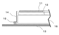
- FIG. 2 shows the internal structure of the power feeding device 2 shown in FIG. 1, and is a perspective view in particular with a cover (not shown) removed.
- FIG. 3 is a longitudinal sectional view of the power feeding device 2 of FIG.
- the power feeding device 2 is sequentially arranged on a magnetic shield plate 13 formed of a material having high magnetic permeability (low magnetic resistance) or low electric resistance (for example, metal).
- Base member 16 magnetic core portion 12, and primary coil 11 (power transmission coil).
- the magnetic shield 13 is installed on a surface (for example, the ground) substantially perpendicular to the magnetic flux generated at the winding center of the primary coil 11.
- an electromagnetic field restricting portion 14 that surrounds the base member 16, the magnetic core portion 12, and the primary coil 11 is fixed to the magnetic shielding plate 13 via the electrical connection portion 15.
- the base member 16 is made of a material other than a conductive material such as metal, for example, a resin containing a ceramic or a filler that improves thermal conductivity.
- a magnetic core 12 made of a high magnetic permeability material typified by ferrite and for concentrating the magnetic flux is disposed on the base member 16.
- the primary coil 11 is configured, for example, by winding a copper wire so as to have an annular shape. Note that the primary coil 11 in FIG. 2 is drawn in a disk shape.
- a substantially cylindrical electromagnetic field restricting part 14 made of a material having high magnetic permeability or low electric resistance (for example, metal) is disposed.
- the electromagnetic field regulating unit 14 is electrically connected to the magnetic shield plate 13 using, for example, screws or the like via electrical connection units 15 provided at a plurality of locations.
- the electromagnetic field restriction unit 14 surrounds the outer periphery of the power transmission coil 11 except for the upper side of the primary coil 11 in order to limit the region of the high frequency electromagnetic field generated by the primary coil 11.
- the power supply device 2 having the above-described configuration may be shallowly embedded in a parking space.
- the power feeding device 2 itself may be configured to be movable. Note that the power feeding device 2 is installed so that the magnetic shield 13 is located on the bottom side of the power feeding device 2 regardless of whether the power feeding device 2 is buried or movable.
- the power receiving device 3 similarly to the power feeding device 2, the power receiving device 3 also includes a magnetic shielding plate, a base member, a magnetic core portion, and a coil (secondary coil).
- a magnetic shield plate of the power receiving device 3 is attached to the vehicle 1.
- the secondary coil of the power receiving device 3 receives electric field generated by the primary coil 11 of the power feeding device 2 and generates electric power.
- the power receiving device 3 does not include an electromagnetic field restriction unit. Specifically, a member for regulating an electromagnetic field, which is formed of a material having high magnetic permeability or low electrical resistance, is not provided outside the outer periphery of the secondary coil of the power receiving device 3. Therefore, the radial direction of the secondary coil of the power receiving device 3 is magnetically opened. As a result, magnetic fluxes in various directions including the radial direction of the secondary coil can pass through the secondary coil of the power receiving device.
- the vehicle 1 is stopped so that the power receiving device 3 (see FIG. 1) and the power feeding device 2 face each other through the air gap. In this way, power is transmitted from the power supply device 2 to the power reception device 3 in a contactless manner with the power reception device 3 and the power supply device 2 positioned so as to face each other.
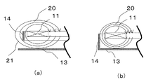
- FIG. 4 is a schematic partial cross-sectional view for explaining the relationship among the primary coil 11, the electromagnetic field restricting portion 14, and the magnetic shielding plate 13, and shows the same position as FIG. FIG. 4A shows a case (comparative example) where the electromagnetic field restricting portion 14 and the magnetic shield 13 are not electrically connected.
- FIG. 4B is a diagram suitable for explaining the technical effect of the first embodiment, and shows a case where the electromagnetic field restricting portion 14 and the magnetic shielding plate 13 are electrically connected.
- the magnetic flux 20 generated by the primary coil 11 is confined inside the electromagnetic field restriction unit 14.
- the electromagnetic field restriction unit 14 passes between the electromagnetic field restriction unit 14 and the magnetic shielding plate 13.
- the magnetic flux 21 which spreads outside and spreads greatly is generated. Further, since the magnetic flux 21 forms a magnetic path that circulates around the electromagnetic field restriction unit 14, the primary coil 11 and the electromagnetic field restriction unit 14 function like a transformer, and a current flows through the electromagnetic field restriction unit 14. As a result, the magnetic flux is lost, and the power supplied from the power feeding device 2 to the power receiving device 2 is lost.
- the magnetic flux 20 is in a direction other than the opening side direction of the electromagnetic field restriction unit 14 (primary coil). 11 (in the radial direction) is suppressed.
- the spread of the magnetic flux 20 in the direction between the radial direction of the primary coil 11 and the opening side direction of the electromagnetic field restriction unit 14 mainly varies depending on the positional relationship between the primary coil 11 and the electromagnetic field restriction unit 14.
- an eddy current is generated by the magnetic flux 20 in the electromagnetic field regulating unit 14 and the magnetic shield 13, and thus an eddy current loss (magnetic flux loss) is generated.
- the electromagnetic field restriction unit 14 and the magnetic shielding plate 13 are made of a low electrical resistance material such as aluminum, and / or a high permeability material such as ferrite is disposed in the vicinity of the primary coil 11, The magnetic flux 20 in the vicinity of the magnetic shield 13 is reduced. Thereby, magnetic flux loss can be reduced.
- the electromagnetic field restricting portion 14 arranged outside the outer periphery of the primary coil 11 is electrically connected to the magnetic shield plate 13, thereby expanding the radial direction of the primary coil 11 of the magnetic flux 20 generated by the primary coil 11.
- the electromagnetic field region 4 can be limited.
- the power can be transmitted efficiently even when the power feeding device 2 or the power receiving device 3 deviates from the facing position where the coils face each other.
- FIG. 5 is a perspective view of the internal structure of the power feeding apparatus according to the second embodiment, in which the height of the electromagnetic field restriction unit 14 is partially different.
- a power receiving device 3 (see FIG. 1) is mounted at a rear position at the bottom of the vehicle 1, a power feeding device 2 is installed at a position opposite to the power receiving device 3, and a structure that causes magnetic flux loss at the rear of the vehicle 1
- FIG. 5 shows a power supply device that addresses the case where it is installed.
- the portion of the electromagnetic field restriction portion 14 on the rear side of the power feeding device 2 that is, the side corresponding to the rear of the vehicle 1 is made higher than the other portions (on the side of the precaution plate 13). The distance from one end to the other is increased). Thereby, spreading of the magnetic flux 20 to the rear of the vehicle 1 can be suppressed, and loss of power supplied from the power feeding device 2 to the power receiving device 2 can be minimized.
- FIG. 6 is a perspective view of the internal structure of the power feeding apparatus according to the third embodiment in which the height of the electromagnetic field restriction unit 14 is partially zero.
- the magnetic flux 20 spreads in a specific direction by setting the arrangement position of the electromagnetic field restriction unit 14 with respect to the primary coil 11 based on the installation state of the power receiving device 3 (see FIG. 1) and the power feeding device 2. Can be suppressed. As a result, the loss of power supplied from the power feeding device 2 to the power receiving device 2 can be minimized.
- by partially setting the height of the electromagnetic field regulating unit 14 to zero it is possible to further suppress the magnetic flux loss caused by the generation of eddy current in the electromagnetic field regulating unit 14.
- the portion on the rear side of the electromagnetic field regulating portion 14 corresponding to the rear of the electric propulsion vehicle 1 is made higher than the other portions.
- portion of the electromagnetic field restricting portion 14 corresponding to the direction in which the magnetic flux loss is small may be made lower than the other portions so that the magnetic flux 20 spreads in the direction in which the magnetic flux loss is small. Thereby, supply electric power can be maximized.
- the non-contact power feeding system according to the present invention minimizes the loss of power supplied from the power feeding device to the power receiving device, and can maximize the power transmission efficiency even with respect to the positional deviation between the coil unit of the power feeding device and the power receiving device. It is useful for power feeding to the power receiving device of the electric propulsion vehicle 1.
Landscapes
- Engineering & Computer Science (AREA)
- Power Engineering (AREA)
- Computer Networks & Wireless Communication (AREA)
- Transportation (AREA)
- Mechanical Engineering (AREA)
- Physics & Mathematics (AREA)
- Electromagnetism (AREA)
- Electric Propulsion And Braking For Vehicles (AREA)
- Current-Collector Devices For Electrically Propelled Vehicles (AREA)
Abstract
La présente invention concerne une unité bobine d'un système d'alimentation en courant électrique sans contact destiné à amener un courant électrique d'un dispositif d'alimentation en courant électrique (2) à un dispositif de réception de courant électrique (3). Un limiteur de champ électromagnétique (14) connecté électriquement à une plaque de blindage magnétique (13) et formé au moyen d'un matériau présentant une perméabilité magnétique élevée ou une faible résistance électrique est disposé sur l'extérieur d'une périphérie extérieure d'une bobine primaire (11) du dispositif d'alimentation en courant électrique (2) et une zone dans laquelle un champ électromagnétique produit par la bobine primaire (11) est distribué étant limitée.
Applications Claiming Priority (2)
| Application Number | Priority Date | Filing Date | Title |
|---|---|---|---|
| JP2011011664A JP2014063768A (ja) | 2011-01-24 | 2011-01-24 | 非接触給電システムに用いられるコイルユニット |
| JP2011-011664 | 2011-01-24 |
Publications (1)
| Publication Number | Publication Date |
|---|---|
| WO2012102008A1 true WO2012102008A1 (fr) | 2012-08-02 |
Family
ID=46580584
Family Applications (1)
| Application Number | Title | Priority Date | Filing Date |
|---|---|---|---|
| PCT/JP2012/000389 Ceased WO2012102008A1 (fr) | 2011-01-24 | 2012-01-23 | Unité bobine utilisée dans un système d'alimentation en courant électrique sans contact |
Country Status (2)
| Country | Link |
|---|---|
| JP (1) | JP2014063768A (fr) |
| WO (1) | WO2012102008A1 (fr) |
Cited By (3)
| Publication number | Priority date | Publication date | Assignee | Title |
|---|---|---|---|---|
| WO2014122121A1 (fr) * | 2013-02-05 | 2014-08-14 | Conductix-Wampfler Gmbh | Unité bobine et dispositif de transfert inductif d'energie electrique |
| WO2016040338A1 (fr) * | 2014-09-09 | 2016-03-17 | Qualcomm Incorporated | Système et procédé pour réduire un flux de fuite dans des systèmes de charge de véhicule électrique sans fil |
| US9923406B2 (en) | 2015-09-04 | 2018-03-20 | Qualcomm Incorporated | System and method for reducing leakage flux in wireless charging systems |
Families Citing this family (1)
| Publication number | Priority date | Publication date | Assignee | Title |
|---|---|---|---|---|
| DE102018103854A1 (de) | 2018-02-21 | 2019-08-22 | Dr. Ing. H.C. F. Porsche Aktiengesellschaft | Ladeeinrichtung |
Citations (5)
| Publication number | Priority date | Publication date | Assignee | Title |
|---|---|---|---|---|
| JP2009060067A (ja) * | 2007-08-31 | 2009-03-19 | Laird Technologies Inc | 電磁干渉シールド及びその製造方法 |
| WO2010041321A1 (fr) * | 2008-10-09 | 2010-04-15 | トヨタ自動車株式会社 | Dispositif de transmission d’énergie sans contact et véhicule équipé de celui-ci |
| WO2010103639A1 (fr) * | 2009-03-12 | 2010-09-16 | トヨタ自動車株式会社 | Véhicule électrique |
| WO2010106648A1 (fr) * | 2009-03-18 | 2010-09-23 | トヨタ自動車株式会社 | Dispositif de réception d'énergie sans contact, dispositif d'émission d'énergie sans contact, système d'alimentation électrique sans contact et véhicule |
| JP2012016250A (ja) * | 2010-07-05 | 2012-01-19 | Panasonic Electric Works Co Ltd | 非接触給電機能付き什器 |
-
2011
- 2011-01-24 JP JP2011011664A patent/JP2014063768A/ja active Pending
-
2012
- 2012-01-23 WO PCT/JP2012/000389 patent/WO2012102008A1/fr not_active Ceased
Patent Citations (5)
| Publication number | Priority date | Publication date | Assignee | Title |
|---|---|---|---|---|
| JP2009060067A (ja) * | 2007-08-31 | 2009-03-19 | Laird Technologies Inc | 電磁干渉シールド及びその製造方法 |
| WO2010041321A1 (fr) * | 2008-10-09 | 2010-04-15 | トヨタ自動車株式会社 | Dispositif de transmission d’énergie sans contact et véhicule équipé de celui-ci |
| WO2010103639A1 (fr) * | 2009-03-12 | 2010-09-16 | トヨタ自動車株式会社 | Véhicule électrique |
| WO2010106648A1 (fr) * | 2009-03-18 | 2010-09-23 | トヨタ自動車株式会社 | Dispositif de réception d'énergie sans contact, dispositif d'émission d'énergie sans contact, système d'alimentation électrique sans contact et véhicule |
| JP2012016250A (ja) * | 2010-07-05 | 2012-01-19 | Panasonic Electric Works Co Ltd | 非接触給電機能付き什器 |
Cited By (5)
| Publication number | Priority date | Publication date | Assignee | Title |
|---|---|---|---|---|
| WO2014122121A1 (fr) * | 2013-02-05 | 2014-08-14 | Conductix-Wampfler Gmbh | Unité bobine et dispositif de transfert inductif d'energie electrique |
| CN104969315A (zh) * | 2013-02-05 | 2015-10-07 | 康达提斯-瓦普弗勒有限公司 | 用于感应式传输电能的线圈单元和装置 |
| WO2016040338A1 (fr) * | 2014-09-09 | 2016-03-17 | Qualcomm Incorporated | Système et procédé pour réduire un flux de fuite dans des systèmes de charge de véhicule électrique sans fil |
| US9889754B2 (en) | 2014-09-09 | 2018-02-13 | Qualcomm Incorporated | System and method for reducing leakage flux in wireless electric vehicle charging systems |
| US9923406B2 (en) | 2015-09-04 | 2018-03-20 | Qualcomm Incorporated | System and method for reducing leakage flux in wireless charging systems |
Also Published As
| Publication number | Publication date |
|---|---|
| JP2014063768A (ja) | 2014-04-10 |
Similar Documents
| Publication | Publication Date | Title |
|---|---|---|
| US11264834B2 (en) | Coil apparatus | |
| JP5921839B2 (ja) | 非接触給電トランス | |
| JP6475684B2 (ja) | コイルユニット | |
| US11328852B2 (en) | Coil device | |
| JP6179375B2 (ja) | コイルユニット | |
| US10270290B2 (en) | Power supply device | |
| JP6370558B2 (ja) | コイルユニット及びそれを有する給電システム | |
| JP6665454B2 (ja) | コイル装置及びコイルシステム | |
| JP5717090B2 (ja) | 受電ユニット、該受電ユニットを備えた充電システム及び電気機器 | |
| JPWO2012039077A1 (ja) | 非接触給電装置 | |
| US20160233723A1 (en) | Enclosures for high power wireless power transfer systems | |
| JP2012228150A (ja) | 共鳴式非接触給電システム、共鳴式非接触給電システムの送電側装置及び車載充電装置 | |
| WO2012090342A1 (fr) | Bobine utilisée dans un système d'alimentation électrique sans contact | |
| JP2015008547A (ja) | 非接触充電装置 | |
| JP2014053366A (ja) | コイル装置 | |
| WO2012102008A1 (fr) | Unité bobine utilisée dans un système d'alimentation en courant électrique sans contact | |
| JP6111645B2 (ja) | コイル装置及びそれを用いたワイヤレス電力伝送システム | |
| US9647535B2 (en) | Compact structure of power-supply apparatus capable of minimizing electromagnetic noise | |
| EP2953148B1 (fr) | Bobine pour dispositif de transmission électrique sans contact ainsi que dispositif de transmission électrique sans contact | |
| WO2014156014A1 (fr) | Dispositif de charge sans contact | |
| JP2015090912A (ja) | リアクトル | |
| JP6454941B2 (ja) | 非接触給電装置および非接触給電システム | |
| US20140085040A1 (en) | Power supply apparatus with fringing flux shielding element | |
| CN106463252B (zh) | 线圈装置 | |
| JP6301675B2 (ja) | コイルユニット及びそれを有する給電システム |
Legal Events
| Date | Code | Title | Description |
|---|---|---|---|
| 121 | Ep: the epo has been informed by wipo that ep was designated in this application |
Ref document number: 12739987 Country of ref document: EP Kind code of ref document: A1 |
|
| NENP | Non-entry into the national phase |
Ref country code: DE |
|
| 122 | Ep: pct application non-entry in european phase |
Ref document number: 12739987 Country of ref document: EP Kind code of ref document: A1 |
|
| NENP | Non-entry into the national phase |
Ref country code: JP |