EP2954863A1 - Verfahren zum Fertigen eines patientenspezifischen Augenhöhlenabdeckgitters und patientenspezifisches Augenhöhlenabdeckgitter - Google Patents
Verfahren zum Fertigen eines patientenspezifischen Augenhöhlenabdeckgitters und patientenspezifisches Augenhöhlenabdeckgitter Download PDFInfo
- Publication number
- EP2954863A1 EP2954863A1 EP14172026.8A EP14172026A EP2954863A1 EP 2954863 A1 EP2954863 A1 EP 2954863A1 EP 14172026 A EP14172026 A EP 14172026A EP 2954863 A1 EP2954863 A1 EP 2954863A1
- Authority
- EP
- European Patent Office
- Prior art keywords
- model
- main body
- orbital
- patient
- channel
- Prior art date
- Legal status (The legal status is an assumption and is not a legal conclusion. Google has not performed a legal analysis and makes no representation as to the accuracy of the status listed.)
- Granted
Links
Images
Classifications
-
- A—HUMAN NECESSITIES
- A61—MEDICAL OR VETERINARY SCIENCE; HYGIENE
- A61B—DIAGNOSIS; SURGERY; IDENTIFICATION
- A61B17/00—Surgical instruments, devices or methods
- A61B17/56—Surgical instruments or methods for treatment of bones or joints; Devices specially adapted therefor
- A61B17/58—Surgical instruments or methods for treatment of bones or joints; Devices specially adapted therefor for osteosynthesis, e.g. bone plates, screws or setting implements
- A61B17/68—Internal fixation devices, including fasteners and spinal fixators, even if a part thereof projects from the skin
- A61B17/80—Cortical plates, i.e. bone plates; Instruments for holding or positioning cortical plates, or for compressing bones attached to cortical plates
- A61B17/8052—Cortical plates, i.e. bone plates; Instruments for holding or positioning cortical plates, or for compressing bones attached to cortical plates immobilised relative to screws by interlocking form of the heads and plate holes, e.g. conical or threaded
- A61B17/8057—Cortical plates, i.e. bone plates; Instruments for holding or positioning cortical plates, or for compressing bones attached to cortical plates immobilised relative to screws by interlocking form of the heads and plate holes, e.g. conical or threaded the interlocking form comprising a thread
-
- A—HUMAN NECESSITIES
- A61—MEDICAL OR VETERINARY SCIENCE; HYGIENE
- A61B—DIAGNOSIS; SURGERY; IDENTIFICATION
- A61B17/00—Surgical instruments, devices or methods
- A61B17/56—Surgical instruments or methods for treatment of bones or joints; Devices specially adapted therefor
- A61B17/58—Surgical instruments or methods for treatment of bones or joints; Devices specially adapted therefor for osteosynthesis, e.g. bone plates, screws or setting implements
- A61B17/68—Internal fixation devices, including fasteners and spinal fixators, even if a part thereof projects from the skin
- A61B17/80—Cortical plates, i.e. bone plates; Instruments for holding or positioning cortical plates, or for compressing bones attached to cortical plates
- A61B17/8061—Cortical plates, i.e. bone plates; Instruments for holding or positioning cortical plates, or for compressing bones attached to cortical plates specially adapted for particular bones
-
- A—HUMAN NECESSITIES
- A61—MEDICAL OR VETERINARY SCIENCE; HYGIENE
- A61B—DIAGNOSIS; SURGERY; IDENTIFICATION
- A61B17/00—Surgical instruments, devices or methods
- A61B17/56—Surgical instruments or methods for treatment of bones or joints; Devices specially adapted therefor
- A61B17/58—Surgical instruments or methods for treatment of bones or joints; Devices specially adapted therefor for osteosynthesis, e.g. bone plates, screws or setting implements
- A61B17/68—Internal fixation devices, including fasteners and spinal fixators, even if a part thereof projects from the skin
- A61B17/80—Cortical plates, i.e. bone plates; Instruments for holding or positioning cortical plates, or for compressing bones attached to cortical plates
- A61B17/8085—Cortical plates, i.e. bone plates; Instruments for holding or positioning cortical plates, or for compressing bones attached to cortical plates with pliable or malleable elements or having a mesh-like structure, e.g. small strips
-
- A—HUMAN NECESSITIES
- A61—MEDICAL OR VETERINARY SCIENCE; HYGIENE
- A61F—FILTERS IMPLANTABLE INTO BLOOD VESSELS; PROSTHESES; DEVICES PROVIDING PATENCY TO, OR PREVENTING COLLAPSING OF, TUBULAR STRUCTURES OF THE BODY, e.g. STENTS; ORTHOPAEDIC, NURSING OR CONTRACEPTIVE DEVICES; FOMENTATION; TREATMENT OR PROTECTION OF EYES OR EARS; BANDAGES, DRESSINGS OR ABSORBENT PADS; FIRST-AID KITS
- A61F2/00—Filters implantable into blood vessels; Prostheses, i.e. artificial substitutes or replacements for parts of the body; Appliances for connecting them with the body; Devices providing patency to, or preventing collapsing of, tubular structures of the body, e.g. stents
- A61F2/02—Prostheses implantable into the body
- A61F2/28—Bones
- A61F2/2875—Skull or cranium
-
- A—HUMAN NECESSITIES
- A61—MEDICAL OR VETERINARY SCIENCE; HYGIENE
- A61F—FILTERS IMPLANTABLE INTO BLOOD VESSELS; PROSTHESES; DEVICES PROVIDING PATENCY TO, OR PREVENTING COLLAPSING OF, TUBULAR STRUCTURES OF THE BODY, e.g. STENTS; ORTHOPAEDIC, NURSING OR CONTRACEPTIVE DEVICES; FOMENTATION; TREATMENT OR PROTECTION OF EYES OR EARS; BANDAGES, DRESSINGS OR ABSORBENT PADS; FIRST-AID KITS
- A61F2/00—Filters implantable into blood vessels; Prostheses, i.e. artificial substitutes or replacements for parts of the body; Appliances for connecting them with the body; Devices providing patency to, or preventing collapsing of, tubular structures of the body, e.g. stents
- A61F2/02—Prostheses implantable into the body
- A61F2/30—Joints
- A61F2/3094—Designing or manufacturing processes
-
- A—HUMAN NECESSITIES
- A61—MEDICAL OR VETERINARY SCIENCE; HYGIENE
- A61B—DIAGNOSIS; SURGERY; IDENTIFICATION
- A61B17/00—Surgical instruments, devices or methods
- A61B2017/00526—Methods of manufacturing
-
- A—HUMAN NECESSITIES
- A61—MEDICAL OR VETERINARY SCIENCE; HYGIENE
- A61B—DIAGNOSIS; SURGERY; IDENTIFICATION
- A61B17/00—Surgical instruments, devices or methods
- A61B17/56—Surgical instruments or methods for treatment of bones or joints; Devices specially adapted therefor
- A61B2017/568—Surgical instruments or methods for treatment of bones or joints; Devices specially adapted therefor produced with shape and dimensions specific for an individual patient
-
- A—HUMAN NECESSITIES
- A61—MEDICAL OR VETERINARY SCIENCE; HYGIENE
- A61B—DIAGNOSIS; SURGERY; IDENTIFICATION
- A61B90/00—Instruments, implements or accessories specially adapted for surgery or diagnosis and not covered by any of the groups A61B1/00 - A61B50/00, e.g. for luxation treatment or for protecting wound edges
- A61B90/08—Accessories or related features not otherwise provided for
- A61B2090/0807—Indication means
-
- A—HUMAN NECESSITIES
- A61—MEDICAL OR VETERINARY SCIENCE; HYGIENE
- A61F—FILTERS IMPLANTABLE INTO BLOOD VESSELS; PROSTHESES; DEVICES PROVIDING PATENCY TO, OR PREVENTING COLLAPSING OF, TUBULAR STRUCTURES OF THE BODY, e.g. STENTS; ORTHOPAEDIC, NURSING OR CONTRACEPTIVE DEVICES; FOMENTATION; TREATMENT OR PROTECTION OF EYES OR EARS; BANDAGES, DRESSINGS OR ABSORBENT PADS; FIRST-AID KITS
- A61F2/00—Filters implantable into blood vessels; Prostheses, i.e. artificial substitutes or replacements for parts of the body; Appliances for connecting them with the body; Devices providing patency to, or preventing collapsing of, tubular structures of the body, e.g. stents
- A61F2/02—Prostheses implantable into the body
- A61F2/30—Joints
- A61F2/3094—Designing or manufacturing processes
- A61F2/30942—Designing or manufacturing processes for designing or making customized prostheses, e.g. using templates, CT or NMR scans, finite-element analysis or CAD-CAM techniques
-
- A—HUMAN NECESSITIES
- A61—MEDICAL OR VETERINARY SCIENCE; HYGIENE
- A61F—FILTERS IMPLANTABLE INTO BLOOD VESSELS; PROSTHESES; DEVICES PROVIDING PATENCY TO, OR PREVENTING COLLAPSING OF, TUBULAR STRUCTURES OF THE BODY, e.g. STENTS; ORTHOPAEDIC, NURSING OR CONTRACEPTIVE DEVICES; FOMENTATION; TREATMENT OR PROTECTION OF EYES OR EARS; BANDAGES, DRESSINGS OR ABSORBENT PADS; FIRST-AID KITS
- A61F2/00—Filters implantable into blood vessels; Prostheses, i.e. artificial substitutes or replacements for parts of the body; Appliances for connecting them with the body; Devices providing patency to, or preventing collapsing of, tubular structures of the body, e.g. stents
- A61F2/02—Prostheses implantable into the body
- A61F2/28—Bones
- A61F2/2875—Skull or cranium
- A61F2002/2878—Skull or cranium for orbital repair
-
- A—HUMAN NECESSITIES
- A61—MEDICAL OR VETERINARY SCIENCE; HYGIENE
- A61F—FILTERS IMPLANTABLE INTO BLOOD VESSELS; PROSTHESES; DEVICES PROVIDING PATENCY TO, OR PREVENTING COLLAPSING OF, TUBULAR STRUCTURES OF THE BODY, e.g. STENTS; ORTHOPAEDIC, NURSING OR CONTRACEPTIVE DEVICES; FOMENTATION; TREATMENT OR PROTECTION OF EYES OR EARS; BANDAGES, DRESSINGS OR ABSORBENT PADS; FIRST-AID KITS
- A61F2/00—Filters implantable into blood vessels; Prostheses, i.e. artificial substitutes or replacements for parts of the body; Appliances for connecting them with the body; Devices providing patency to, or preventing collapsing of, tubular structures of the body, e.g. stents
- A61F2/02—Prostheses implantable into the body
- A61F2/30—Joints
- A61F2002/30001—Additional features of subject-matter classified in A61F2/28, A61F2/30 and subgroups thereof
- A61F2002/30108—Shapes
- A61F2002/3011—Cross-sections or two-dimensional shapes
- A61F2002/30112—Rounded shapes, e.g. with rounded corners
-
- A—HUMAN NECESSITIES
- A61—MEDICAL OR VETERINARY SCIENCE; HYGIENE
- A61F—FILTERS IMPLANTABLE INTO BLOOD VESSELS; PROSTHESES; DEVICES PROVIDING PATENCY TO, OR PREVENTING COLLAPSING OF, TUBULAR STRUCTURES OF THE BODY, e.g. STENTS; ORTHOPAEDIC, NURSING OR CONTRACEPTIVE DEVICES; FOMENTATION; TREATMENT OR PROTECTION OF EYES OR EARS; BANDAGES, DRESSINGS OR ABSORBENT PADS; FIRST-AID KITS
- A61F2/00—Filters implantable into blood vessels; Prostheses, i.e. artificial substitutes or replacements for parts of the body; Appliances for connecting them with the body; Devices providing patency to, or preventing collapsing of, tubular structures of the body, e.g. stents
- A61F2/02—Prostheses implantable into the body
- A61F2/30—Joints
- A61F2002/30001—Additional features of subject-matter classified in A61F2/28, A61F2/30 and subgroups thereof
- A61F2002/30316—The prosthesis having different structural features at different locations within the same prosthesis; Connections between prosthetic parts; Special structural features of bone or joint prostheses not otherwise provided for
- A61F2002/30535—Special structural features of bone or joint prostheses not otherwise provided for
- A61F2002/30617—Visible markings for adjusting, locating or measuring
Definitions
- the invention relates to a patient-specific Brightonenabdeckgitter to all four orbital walls, in particular in the manner of a "three-dimensional orbita mesh", with a curved / S-shaped bent / multi-curved main body having an outer, normally circumferentially closed end edge / skirt, wherein the main body a Underside, which faces in the implanted state or the eye cavity forming bone and the main body has an upper side facing away from the underside.
- the invention also relates to a method for producing a patient-specific adapted Fernhöhlenabdeckgitters for all four orbital walls. A coupling ability to any defects in the midface is given.
- an array of elongated parts is subsumed at regular or irregular intervals. It can have a netlike surface structure.
- an implant for use as a replacement for an orbit and optionally also a medial and lateral orbital wall in the form of an integrally preformed plate comprising a first portion, a second portion and a third portion
- the first portion according to an orbital base, and the second portion are shaped according to a medial side wall, and the first portion and the second portion abut against a first predetermined line, the third portion being at Attachment of the implant is located on the anterior orbital rim, wherein it is particularly found that the first predetermined line is defined in said document as a break line along which a doctor can easily remove a segment.
- Grid-like plates are also known in a similar form for use on other parts of the body.
- the DE 197 46 396 A1 a grid for the fixation of bone parts or for the bridging of bone defects. Such a grid can also be used on the skull.
- a grille is proposed for use in the skull and jaw area, consisting of biocompatible materials with a net-like structure and with recesses for receiving bone screws, with which the grid can be attached to the bone.
- the webs form meandering, continuous, periodic web rows along the main axis of the grid.
- the orbital masking grid ie the device intended to be in contact with the orbital floor, should not interfere with eyeball picking when mounted on the bone.
- this eyeball image is not spherical, but extends oblong, in particular S-shaped.
- the orbital cover can be easily and precisely spent on or in the patient.
- the patient may be a mammal, especially a human or (mammal) animal.
- the Augenhöhlenabdeckgitter is to spend between a soft tissue filling the eye socket and the bone structure forming the actual eye socket.
- the Augenhöhlenabdeckgitter is then an implant that rests on the bone structure, at least with as three points in contact there is located and is covered by soft tissue after implantation. Of course it is also possible to use less than three points of support.
- the insertion can be made more precisely, atraumatically and without injury / injury-free;
- objectivability exists for positional control in X-ray-based imaging methods.
- the compatibility of the orbital masking grid in the patient is significantly improved.
- the wearing comfort is increased.
- the channel connects two points linearly, that is, at least partially linearly configured, or better formed linearly in whole.
- the main body is designed as a web-forming, perforated component.
- the adaptability to the example. Human body is thereby improved.
- the danger of training a completed Reduced space, ie in the case of, for example, bleeding, the lattice openings allow the flow of blood in adjacent paranasal sinuses.
- the slots are aligned (almost) orthogonally to the terminal edge / border and / or are distributed equidistant to each other.
- the insertion process is thus easier to control.
- Other advantages, such as obtaining a particularly rigid implant, can also be achieved.
- the channel has two raised from the top lifting and equally spaced extending channel walls, so a control instrument can be easily placed on the channel and act as a control when inserting. By the sublime designed channel walls leaving the control instrument to the outside of the channel is effectively prevented.
- a structure weakening is avoided if the channel between the channel walls has a channel bottom, which is formed by the top of the main body or extends at least in the surface formed by the surface. Also, the production can then be carried out inexpensively.
- the channel which is preferably interrupted / continuous or sectionally interrupted, runs from a front edge, which is nearest to a surgeon, to a tip region which, in the implanted state, is nearest or close to an optic nerve / visual canal. Placing the tip area on the bone is simplified while avoiding irritation or damage to the optic nerve / visual canal. Also, it will be easier to contact the tip area with a deep inside of soft tissue To bring bone section. It is advantageous if the implant in the tip area is also over-arched to obtain a greater distance to the optic nerve.
- the insertion process becomes even more precise feasible if a second channel for representing a further insertion vector is present.
- the second channel may then be similar or identical to the first channel and indicates the transition between the orbital floor and the lateral wall.
- the first channel may be aligned transversely to the second channel, in particular at an angle ⁇ , which is in the range of 20 ° to 40 °, in particular 22.5 °, be angularly offset.
- channel edges form a guide for an inserted and pushed along them control instrument, slippage of the control instrument is efficiently avoided.
- a navigation stop preferably haptically or tactilely detectable by the control instrument, in the form of an elevation or recess is present / formed, and preferably a plurality of navigation stops per channel are formed, wherein in the channels equal to many or different numbers of navigation stops per channel are present, about in the second channel a navigation stop less than in the first channel.
- Navigation stops can be placed on the entire body of the implant, but preferably on the canal. The navigation stops are defined as landmarks to be controlled intraoperatively.
- a Trajoktorien declaration can be realized, which receives the inserted insertion vectors and can be administered.
- first channel is aligned parallel to a sagittal plane of the patient to be treated and / or the second or first channel is aligned parallel to an oblique-sagittal plane of the patient to be treated.
- the tip region has a different curvature than the majority of the main body, in particular as the directly adjacent / adjacent region of the main body, is preferably convex, ie.
- the direction of the bone is increasingly curved / running, so injury-free handling of the eye socket lattice when implanting in the example. Human body is facilitated.
- first channel and the second channel meet in the tip region or nearly hit.
- the point of intersection of the two channels is outside the implant, for example, by about 1 mm to about 4 mm, in particular about 1.3 mm outside the terminal edge of the eyelet lattice is present.
- An advantageous exemplary embodiment is also characterized in that a length scale representative of the dimensions present on the main body is applied.
- a further development is characterized in that the characters relevant for the length scale, such as numerals, are introduced / applied next to one of the channels, for example to the left or right next to the first or second channel, preferably in the manner of a (calibrated ) Rulers.
- the distance from the tip area can thereby be marked.
- the distances of approx. 15 mm, approx. 25 mm and approx. 35 mm as well as intermediate values such as approx. 10 mm, approx. 20 mm and / or approx. 30 mm can then be simply marked.
- the markings can be set at 5 mm intervals.
- the front edge has a convex curvature on the upper side and / or a concave curvature on the underside. Also, it can then facilitate the gripping for a surgeon. In particular, the manual holding the eyelet lattice at the front edge with the fingers of the surgeon is facilitated.
- the attachment of the orbital grid to the bone becomes more precise if there is at least one through hole for receiving a screw securing the eyelet to the bone, preferably a plurality of through holes for a plurality of screws and / or the through hole across the top and / or bottom of the main body (in the area of the through hole) is aligned to follow a Bohrvektor. Also slipping of the orbital grid relative to the bone is thereby effectively prevented. It has proven useful to calculate a bolt vector in the through hole in order to know beforehand where most of the bone supply is available and to use it meaningfully.
- the main body is designed as a plate, mesh and / or multi-layer component.
- passageways or perforations are designed as a closure system, the compatibility of the orbit of the patient's orbit is improved, in particular in order to provide an outlet for possible rebleeding.
- An advantageous embodiment is also characterized in that the end edge of thicker material than the (vast) rest of the main body is shaped in the manner of an atraumatic acting cord.
- a particularly resilient / rigid implant can be created.
- a medial wall is only as high as patient-specific necessary, but designed as high as possible, if there is a need for it. Patient compatibility is improved when the tip region is inverted to form a snow pusher-like curve to maintain a curvature away from the optic nerve.
- the invention also relates to a method for producing a patient-specific adapted Fernhöhlenabdeckgitters.
- an inventive Fernhöhlenabdeckgitter can be created.
- individual steps are run through, which preferably take place consecutively in time.
- a (3D) primary model of the bone structure to be covered or replaced is created in the region of an eye socket of a patient (human or animal) to be treated.
- a further step concerns the definition of a border region representative of the maximum spatial extent of the planned orbital masking grid, at least in terms of its areal extent.
- a further step concerns the transfer of a (2D) secondary model to the (3D) primary model, for example within a predefined / arbitrary boundary region, such that the geometric structure of the primary model is transferred to the original form of the original secondary model and converted to a (3D -) Tertiary model leads.
- the production of the orbital masking grid is carried out on the basis of the data after a separating step from the original (3D) primary model, ie on the basis of the (3D) tertiary model.
- a 2D template is virtually projected onto a pad, wherein the pad may have patient-specific imitated sublimities or the patient-specific features is modeled.
- the primary model is a 3D model and / or the secondary model is a 2D model and / or the tertiary model is a 3D model.
- the orbital grid consists only of one or more metal material (s) or only of plastic or a mixture of metal and plastic.
- ceramic components may be added.
- the orbital grid can also be made entirely of ceramic. Zirconium oxide or hydroxyapatite is suitable for this purpose.
- the secondary model is constructed / assembled from several layers.
- An advantageous embodiment is also characterized in that when transferring or planning / laying out the primary or secondary model, a desired deviation from the 3D patient data is accepted / used to make the edge of the orbital grid optimized for the operator and / or optimized for the implantation process.
- the tip portion of the eyelid lattice While preparing the tip portion of the eyelid lattice to contact the bone, it becomes curved, e.g., more curved than dictated by the 3D patient data, and / or the anterior edge of the eyelid lattice is prepared as the handle area for (manual) operator access, such as is curved, for example, more curved than specified by the 3D patient data, so a particularly safe manageable eyelet grid can be created.
- perforations or passageways are deliberately orthogonal to a patient-specific vector, such as insertion vector, relevant to the deployment / implantation procedure.
- a particularly good matching can be achieved if a cord present at the terminal edge has a thickness of approximately 0.3 to approximately 0.7 mm, for example approximately 0.5 mm, and the area of the main body present therebetween has a thickness of about 0.1 mm to about 0.5 mm, about 0.3 mm.
- the values are zigzags and may be subject to a deviation of 10% or 20%.
- an internal matrix is selected selectively / freely with regard to one or more factors of structure, geometry, pore size and biomechanical properties, for example in adaptation / imitation / improvement of the material to be replaced / supplemented by the respective anatomical region of the patient.
- a patient-specific identification such as in the manner of a barcode and / or a string of letters and / or numbers, is applied to the orbital grid, for example during the manufacturing step of that material which forms the eyelet grid, preferably in one (Laser) sintering process as sublimity, in particular for reproducing the patient name and / or the implantation position / position.
- the individual combined and at least partially covering Fernhöhlenabdeckgitter can also have different shapes per se. For example, a cylindrical or triangular shape may be favored.
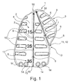
- FIG. 1 a first embodiment of a Fernhöhlenabdeckgitters 1 according to the invention is shown.
- the orbital cover grid is designed as an "orbita mesh". It has a multiply curved / curved / curved main body 2.
- the main body 2 has on its outside a substantially circumferential / closed outer end edge / skirting 3.
- An underside of the orbital cover grid 1, in particular of the main body 2 and the end edge / skirt 3, is designed to be patient-specific.
- the internal and external structure is patient-specific.
- the internal matrix of the main body and the material used, for example a titanium alloy, is adapted to the adjoining patient-specific anatomical region in terms of bending stiffness and / or modulus of elasticity, preferably as closely as possible copied.
- the orbital masking grid 1 can be adapted specifically to the bone or sockets forming the eye socket.
- the top of the implant / orbital cover grille 1 is provided with the reference numeral 4.
- a first channel 5 and a second channel 6 are formed on this upper side 4. Both channels 5 and 6 are linear and are visually and tactilely recognizable.
- Each channel 5 or 6 defines an insertion vector.
- Each channel 5 and 6 each have two channel walls 7, which protrude orthogonally from the top 4, wherein between the two channel walls 7 of a channel 5 and 6, a channel bottom 8 is defined.
- a navigation stop 9 is present in / on / on the channel bottom 8 .
- two navigation stops 9 are provided, whereas in the second channel 6 only a single navigation stop 9 is provided.
- perforations or slots / passage slots 10 are kept in the manner of through holes. They have an elongated form. They each run orthogonally to the end edge / border 3, which by a cord 11 is formed, which has a nearly circular, elliptical or rounded cross-section. The cord therefore acts atraumatic.
- An exact tear path region 13 is also physically designed and predefined.
- the through holes 14 There are four through holes 14 held in a front edge 15 of the orbital cover grid 1.
- the through holes 14 define a drilling vector, or follow a predetermined Bohrvektor.
- the drilling vector is operator specific.
- the drill vector is obliquely on the top 4 and / or bottom of the main body 2 of the orbital masking grid 1.
- screws can be introduced, which can be anchored in the bone.
- a tip portion 16 is present at the opposite end of the main body 2. There, inside or outside the material forming the main body 2, the insertion vectors meet.
- a length scale 17 formed by numbers such as the numbers 15, 25, and 35 is formed on the left side of the first channel 5 beginning / following from the tip portion 16.
- the length scale 17 is designed in the manner of a (calibrated) ruler.
- the slots / passageways 10 form a drainage system.
- a critical area is predefined in terms of the visual canal / optic nerve.
- the insertion vector on which the channels 5 and 6 are based is provided with the reference numeral 18.
- the channels 5 and 6 are not only advantageous in implanting, so inserting the Augenhöhlenabdeckgitters 1, but also in the subsequent control of the implanting process. This enables a quality assurance procedure without injuring the patient.
- An adjustment of the real position of the eye socket cover grid 1 in the patient with a desired position on the computer is always easy to carry out. Postoperative control of the situation is facilitated. Matching with the 3D dataset as planned was enabled. This can The patient will be provided with a reference point and read into the calculator. In particular, there are three reference points.
- the channels 5 and 6 then act as a guide with intermediate points / depressions. The guide path is thus the first channel 5 or the second channel 6 and the intermediate points / depressions are then the navigation stops 9.
- the channels 5 and 6 thus form a physical double contour / line for improved guidance of a control instrument.
- the tip region 16 may be formed in the manner of an inverted snow pusher-like tip, i. form a curvature protruding from the optic nerve, so that an impingement of the eye muscle or a mechanical irritation / perforation of the optic nerve is excluded / avoided. Perforations, such as the slots / passageways 10 are also deliberately oriented orthogonal to a patient-specific vector, in particular to the insertion vector 18.
- the tip portion 16 is prepared for abutment with the bone.
- the edge in particular formed by the end edge / skirt 3, can be planned so that the implant forms a supernatant, which can be brought into contact with the bone and / or provides a handle for the surgeon.
- a secondary model can be applied to a primary model.
- the secondary model can be a conglomerate of different layers and shapes. Separating the implant from the 3D model is desirable.
- the implant can then be a model, for example in the form of a standardized 3D dataset form, for example in the form of an STL dataset.
- the secondary model can be a "BMP template", whereby JPEG, TIFF and similar formats are also possible.
- the material of the orbital masking grid 1 also absorbable material can be used.
Landscapes
- Health & Medical Sciences (AREA)
- Orthopedic Medicine & Surgery (AREA)
- Life Sciences & Earth Sciences (AREA)
- Surgery (AREA)
- Engineering & Computer Science (AREA)
- Animal Behavior & Ethology (AREA)
- Veterinary Medicine (AREA)
- Public Health (AREA)
- Biomedical Technology (AREA)
- Heart & Thoracic Surgery (AREA)
- General Health & Medical Sciences (AREA)
- Medical Informatics (AREA)
- Nuclear Medicine, Radiotherapy & Molecular Imaging (AREA)
- Neurology (AREA)
- Molecular Biology (AREA)
- Transplantation (AREA)
- Vascular Medicine (AREA)
- Oral & Maxillofacial Surgery (AREA)
- Cardiology (AREA)
- Neurosurgery (AREA)
- Manufacturing & Machinery (AREA)
- Prostheses (AREA)
- Orthopedics, Nursing, And Contraception (AREA)
Abstract
Description
- Die Erfindung betrifft ein patientenspezifisches Augenhöhlenabdeckgitter zu allen vier Augenhöhlenwänden, insbesondere nach Art eines "dreidimensionalen Orbita Meshes", mit einem geschwungenen / S-förmig gebogenen / mehrfach gekrümmten Hauptkörper, der eine äußere, normalerweise umlaufend geschlossene Abschlusskante / Einfassung aufweist, wobei der Hauptkörper eine Unterseite aufweist, die im implantierten Zustand dem oder den die Augenhöhle ausformenden Knochen zugewandt ist und der Hauptkörper eine der Unterseite abgewandte Oberseite aufweist.
- Die Erfindung betrifft auch ein Verfahren zum Herstellen eines patientenspezifisch angepassten Augenhöhlenabdeckgitters für alle vier Augenhöhlenwände. Eine Ankoppelungsfähigkeit an beliebige Defekte im Mittelgesicht ist gegeben.
- Unter einem Gitter wird eine Anordnung aus länglichen Teilen in regelmäßigen oder unregelmäßigen Abständen subsumiert. Es kann eine netzartig ausgestaltete Flächenstruktur haben.
- Aus dem Stand der Technik sind bereits Augenhöhlenabdeckgitter bekannt, wie beispielsweise aus der
EP 1 965 735 B1 . Dort wird ein Implantat zur Verwendung als Ersatz eines Orbitabodens eingesetzt. Das Implantat ist als Augenhöhlenabdeckgitter ausgestaltet, liegt also am Orbitaboden auf. So ein Implantat, wie ein "Mesh" bzw. Gitter kann auch zur seitlichen Orbitawandrekonstruktion verwendet werden. Es kann auch freitragend eingesetzt werden und muss nicht unbedingt am Boden aufliegen. In der besagten Druckschrift wird ein Implantat für die Verwendung als Ersatz eines Augenhöhlengrunds und optional auch einer medialen und lateralen Augenhöhlenwandung in der Form einer einstückig vorgeformten Platte, die einen ersten Abschnitt, einen zweiten Abschnitt und einen dritten Abschnitt umfasst, vorgestellt, wobei der erste Abschnitt gemäß einem Augenhöhlengrund und der zweite Abschnitt gemäß einer medialen Seitenwandung geformt sind und der erste Abschnitt und der zweite Abschnitt an einer ersten vorbestimmten Linie anliegen, wobei der dritte Abschnitt zur Befestigung des Implantats am vorderen Augenhöhlenrand angeordnet ist, wobei als besonders herausgestellt ist, dass die erste vorbestimmte Linie eine in der besagten Druckschrift als Bruchlinie definiert ist, entlang welcher ein Arzt ein Segment leicht entfernen kann. - Gitterartig ausgebildete Platten sind auch in ähnlicher Form zum Einsatz an anderen Teilen des Körpers bekannt.
- So offenbart beispielsweise die
DE 197 46 396 A1 ein Gitter für die Fixierung von Knochenteilen oder für die Überbrückung von Knochenfehlstellen. Ein solches Gitter kann auch am Schädel eingesetzt werden. Letztlich wird in dieser deutschen Druckschrift ein Gitter zur Anwendung im Schädel- und Kieferbereich vorgeschlagen, bestehend aus biokompatiblen Materialien mit einer netzartigen Struktur und mit Ausnehmungen zur Aufnahme von Knochenschrauben, mit denen das Gitter am Knochen befestigbar ist. Die Stege bilden mäanderförmige, durchgehende, periodische Stegreihen entlang der Hauptachse des Gitters. - Das Augenhöhlenabdeckgitter, also jene Vorrichtung, die zum In-Kontakt-Gelangen mit dem Orbitaboden vorgesehen ist, darf bei Anbringung am Knochen die Augapfelaufnahme nicht behindern. Jene Augapfelaufnahme ist jedoch nicht sphärisch, sondern erstreckt sich länglich, insbesondere S-förmig.
- Die aus dem Stand der Technik bekannten Augenhöhlenabdeckgitter sind leider häufig zu groß, nicht angepasst an den jeweils zu behandelnden individuellen Schädelknochen und/oder Defekt und auch häufig schwierig anzupassen.
- Es ist die Aufgabe der Erfindung, hier Abhilfe zu bieten und eine möglichst optimale und patientenspezifische Ausgangsstruktur eines Augenhöhlenabdeckgitters dem Operateur zur Verfügung zu stellen, insbesondere ein solches Augenhöhlenabdeckgitter, was nicht zu groß ist, bereits vorangepasst an den jeweiligen zu behandelnden Defekt ist und einfach feinanpassbar ist. Ferner soll ein Verfahren vorgestellt werden, das ein einfaches Herstellen eines solchen Augenhöhlenabdeckgitters ermöglicht. Letztlich soll auch ein Verfahren vorgestellt werden, um schnell und präzise Verletzungen des Orbitabodens und der seitlichen Orbitawände dauerhaft zu behandeln, mit der Option der Ankopplung an z.B. ebenfalls zu ersetzende Mittelgesichtsstrukturen - wie z.B. im Falle ausgedehnter tumorbedingter Resektionsdefekte.
- Diese Aufgabe wird erfindungsgemäß dadurch bei einem gattungsgemäßen Augenhöhlenabdeckgitter gelöst, dass auf der Oberseite wenigstens ein optisch erkennbarer, Kanal zum Darstellen wenigstens eines Insertionsvektors ausgeprägt ist.
- Auf diese Weise kann das Augenhöhlenabdeckgitter einfacher und präziser an bzw. in den Patienten verbracht werden. Der Patient kann ein Säugetier sein, insbesondere ein Mensch oder ein (Säuge-)Tier. Dabei ist das Augenhöhlenabdeckgitter zwischen einem die Augenhöhle ausfüllenden Weichgewebe und die die eigentliche Augenhöhle bildende Knochenstruktur zu verbringen. Das Augenhöhlenabdeckgitter, ist dann ein Implantat, das auf der Knochenstruktur aufliegt, zumindest mit möglichst drei Punkten in Kontakt dort befindlich ist und von Weichgewebe nach der Implantierung bedeckt ist. Natürlich ist es möglich auch weniger als drei Auflagepunkte zu nutzen. Ist das Augenhöhlenabdeckgitter erfindungsgemäß ausgestaltet, kann das Einsetzen präziser, atraumatisch und verletzungsfrei / verletzungsfreier erfolgen; insbesondere besteht Objektivierbarkeit für die Lagekontrolle in röntgenbasierten Bildgebungsverfahren. Die Verträglichkeit des Augenhöhlenabdeckgitters beim Patienten wird wesentlich verbessert. Der Tragekomfort wird erhöht.
- Vorteilhafte Ausführungsformen sind in den Unteransprüchen beansprucht und werden nachfolgend näher erläutert.
- So ist es von besonderem Vorteil, wenn der Kanal zwei Punkte linear verbindet, also wenigstens abschnittsweise linear ausgestaltet ist, oder besser in Gänze linear ausgeformt ist.
- So ist es von Vorteil, wenn der Hauptkörper als ein stegausbildendes, perforiertes Bauteil ausgebildet ist. Die Adaptierbarkeit an den bspw. menschlichen Körper wird dadurch verbessert. Außerdem ist die Gefahr der Ausbildung eines abgeschlossenen Raumes reduziert, d.h. im Falle von z.B. Nachblutungen erlauben die Gitteröffnungen das Ablaufen von Blut in benachbarten Nasennebenhöhlen.
- Wenn im Hauptkörper Stege so angeordnet sind, dass sich durch den Hauptkörper längliche, sich in der durch den Hauptkörper aufgespannten Fläche verlaufende Durchgangsschlitze ziehen, insbesondere solche, die sich von der Unterseite zur O-berseite des Hauptkörpers erstrecken, so wird die Verträglichkeit des Augenhöhlenabdeckgitters beim Patienten verbessert, Gewicht verringert, Material eingespart, Kosten reduziert und die Ausbildung eines Abflusssystems kreierbar.
- Es ist auch zweckmäßig, wenn die Schlitze (nahezu) orthogonal zur Abschlusskante / Einfassung ausgerichtet sind und / oder zueinander äquidistant verteilt sind. Der Einsetzvorgang wird dadurch besser kontrollierbar. Auch andere Vorteile, wie das Erhalten eines besonders rigiden Implantats, können sich einstellen.
- Wenn der Kanal zwei sich von der Oberseite erhaben abhebende und zueinander gleich beabstandet verlaufende Kanalwände besitzt, so kann ein Kontrollinstrument einfach auf den Kanal aufgesetzt werden und beim Einsetzen kontrollierend fungieren. Durch die erhaben ausgestalteten Kanalwände wird ein Verlassen des Kontrollinstrumentes nach außerhalb des Kanals wirkungsvoll verhindert.
- Eine Strukturschwächung wird vermieden, wenn der Kanal zwischen den Kanalwänden einen Kanalgrund aufweist, der durch die Oberseite des Hauptkörpers gebildet ist oder wenigstens in der durch die Oberfläche gebildeten Fläche verläuft. Auch kann die Fertigung dann kostengünstig durchgeführt werden.
- Es ist auch von Vorteil, wenn der vorzugsweise unterbrochen / durchgehend oder abschnittsweise unterbrochen ausgestaltete Kanal von einem vorderen Rand, der einem Operateur nächstgelegen ist, bis zu einem Spitzenbereich verläuft, der im implantierten Zustand einem Sehnerv / Sehkanal nächstgelegen oder nahegelegen ist. Das Aufsetzen des Spitzenbereichs am Knochen wird unter Vermeidung einer Irritation oder Beschädigung des Sehnervs / des Sehkanals vereinfacht. Auch wird es einfacher, den Spitzenbereich in Kontakt mit einem tief im Inneren von Weichgewebe vorhandenem Knochenabschnitt zu bringen. Dabei ist es von Vorteil, wenn das Implantat im Spitzenbereich zusätzlich noch überbogen wird, um einen größeren Abstand zum Sehnerv zu erhalten.
- Der Einsetzvorgang wird noch präziser durchführbar, wenn ein zweiter Kanal zum Darstellen eines weiteren Insertionsvektors vorhanden ist. Der zweite Kanal kann dann ähnlich oder identisch zum ersten Kanal ausgebildet sein und gibt den Übergang zwischen dem Orbitaboden und der seitlichen Wand an.
- Insbesondere kann der erste Kanal zum zweiten Kanal quer verlaufend ausgerichtet sein, insbesondere um einen Winkel α, der im Bereich von 20° bis 40°, insbesondere 22,5°, liegt, winkelig versetzt sein.
- Wenn die Kanalränder eine Führung für ein zwischen ihnen eingesetztes und entlang geschobenes Kontrollinstrument bilden, wird ein Verrutschen des Kontrollinstrumentes effizient vermieden.
- Damit das Einsetzen des Augenhöhlenabdeckgitters / des Implantats abschnittsweise unterbrochen und / oder kontrolliert werden kann, ist es von Vorteil, wenn zwischen den Kanalwänden und / oder auf / in dem Kanalgrund ein von dem Kontrollinstrument vorzugsweise haptisch oder taktil erfassbarer Navigations-Stopp in Form einer Erhebung oder Vertiefung vorhanden / ausgebildet ist, und vorzugsweise mehrere Navigations-Stopps pro Kanal ausgebildet sind, wobei in den Kanälen gleich viele oder unterschiedlich viele Navigations-Stopps pro Kanal vorhanden sind, etwa im zweiten Kanal ein Navigations-Stopp weniger als im ersten Kanal. Navigations-Stopps können auf dem kompletten Körper des Implantats gesetzt werden, vorzugsweise jedoch auf dem Kanal. Die Navigations-Stops sind dabei als intraoperativ anzusteuernde Landmarken definiert. Ferner ist eine Trajoktorienplanung realisierbar, die die eingelassenen Insertionsvektoren aufnimmt und verabfolgen lässt.
- Es ist auch von Vorteil, wenn der erste Kanal parallel zu einer Sagittalebene des zu behandelnden Patienten ausgerichtet ist und / oder der zweite oder erste Kanal parallel zu einer Schrägsagittalebene des zu behandelnden Patienten ausgerichtet ist. Eine im dreidimensionalen Raum geschwungene Einsetzbewegung lässt sich dann einfacher vom Operateur auf ihre Präzision kontrollieren.
- Wenn der Spitzenbereich eine andere Krümmung als der überwiegende Teil des Hauptkörpers, insbesondere als der direkt anschließende / benachbarte Bereich des Hauptkörpers, aufweist, vorzugsweise konvex gewölbt ist, d.h. beispielsweise in Richtung des Knochens zunehmend gekrümmt / verlaufend ist, so wird eine verletzungsfreie Handhabung des Augenhöhlengitters beim Implantieren in den bspw. menschlichen Körper erleichtert.
- Es ist zweckmäßig, wenn sich der erste Kanal und der zweite Kanal im Spitzenbereich treffen oder nahezu treffen. Natürlich ist es möglich, dass der Schnittpunkt der beiden Kanäle außerhalb des Implantats liegt, bspw. um ca. 1 mm bis ca. 4 mm, insbesondere ca. 1,3 mm außerhalb der Abschlusskante des Augenhöhlengitters vorhanden ist.
- Ein vorteilhaftes Ausführungsbeispiel ist auch dadurch gekennzeichnet, dass eine für die auf dem Hauptkörper vorhandenen Abmessungen repräsentative Längenskala aufgebracht ist.
- Dabei ist eine Weiterbildung dadurch gekennzeichnet, dass die für die Längenskala relevanten Zeichen, wie Ziffern, neben einem der Kanäle, etwa links oder rechts neben dem ersten oder zweiten Kanal, auf / in der Oberseite eingebracht / aufgebracht sind, vorzugsweise nach Art eines (kalibrierten) Lineals. Insbesondere lässt sich die Distanz vom Spitzenbereich dadurch markieren. Die Abstände von ca. 15 mm, ca. 25 mm und ca. 35 mm sowie Zwischenwerte wie ca. 10 mm, ca. 20 mm und / oder ca. 30 mm lassen sich dann einfach kennzeichnen. Die Markierungen können in 5 mm Abständen gesetzt werden. Damit die Anpassung an den Patienten verbessert wird, ist es von Vorteil, wenn der vordere Rand auf der Oberseite eine konvexe Wölbung und / oder auf der Unterseite eine konkave Wölbung aufweist. Auch lässt sich dann das Greifen für einen Operateur erleichtern. Insbesondere das manuelle Halten des Augenhöhlengitters am vorderen Rand mit den Fingern des Operateurs wird erleichtert.
- Die Befestigung des Augenhöhlengitters am Knochen wird präziser, wenn im vorderen Rand wenigstens ein Durchgangsloch zum Aufnehmen von einer das Augenhöhlengitter am Knochen befestigenden Schraube vorhanden ist, vorzugsweise mehrere Durchgangslöcher für mehrere Schrauben und / oder das Durchgangsloch quer zur Ober- und / oder Unterseite des Hauptkörpers (im Bereich des Durchgangsloches) ausgerichtet ist, um einem Bohrvektor zu folgen. Auch wird ein Verrutschen des Augenhöhlengitters relativ zum Knochen dadurch wirkungsvoll verhindert. Dabei hat es sich bewährt, im Durchgangsloch einen Schraubenvektor zu berechnen, um vorher zu wissen, wo das meiste Knochenangebot vorhanden ist und dieses sinnvoll zu nutzen.
- Es ist von Vorteil, wenn ein Tränenwegsbereich physisch vordefiniert / ausgebildet ist.
- Auch ist es vorteilhaft, wenn der Hauptkörper als Platte, Netz und / oder Mehrschichtbauteil ausgebildet ist.
- Wenn die Durchgangsschlitze oder Perforationen als Abschlusssystem ausgelegt sind, wird die Verträglichkeit des Augenhöhlengitters beim Patienten verbessert, insbesondere, um eine Abflussmöglichkeit bei eine möglichen Nachblutung zu schaffen.
- Ein vorteilhaftes Ausführungsbeispiel ist auch dadurch gekennzeichnet, dass die Abschlusskante aus dickerem Material als der (überwiegende) Rest des Hauptkörpers nach Art einer atraumatisch wirkenden Kordel ausgeformt ist.
- Als vorteilhaft für die Verträglichkeit hat es sich auch herausgestellt, wenn das Augenhöhlengitter auf einen spezifischen Patienten vorbereitet und / oder angepasst ist.
- Wenn die Durchgangsschlitze so angeordnet sind, dass ein unbeabsichtigtes Umklappen von Teilbereichen des Hauptkörpers erschwert oder ausgeschlossen ist, wird ein besonders belastbares / rigides Implantat schaffbar / geschaffen. Insbesondere ist es von Vorteil, wenn eine mediale Wand nur so hoch ist, wie patientenspezifisch notwendig, aber möglichst hoch ausgestaltet ist, wenn die Notwendigkeit dafür besteht. Die Patientenverträglichkeit wird verbessert, wenn der Spitzenbereich umgedreht schneeschieberartig ausgebildet ist, um eine vom Sehnerv wegragende Krümmung zu erhalten.
- Die Erfindung betrifft auch ein Verfahren zum Herstellen eines patientenspezifisch angepassten Augenhöhlenabdeckgitters. Dabei kann ein erfindungsgemäßes Augenhöhlenabdeckgitter geschaffen werden. Erfindungsgemäß werden dabei einzelne Schritte durchlaufen, die vorzugsweise zeitlich nacheinander ablaufen. So wird in einem Schritt ein (3D-)Primärmodell der abzudeckenden oder ersetzenden Knochenstruktur im Bereich einer Augenhöhle eines zu behandelnden (menschlichen oder tierischen) Patienten geschaffen. Ein weiterer Schritt betrifft das Festlegen einer für die maximale räumliche Ausdehnung des geplanten Augenhöhlenabdeckgitters repräsentativen Grenzbereichs, zumindest in puncto seiner flächigen Ausdehnung. Ein weiterer Schritt betrifft das Überführen eines (2D-)Sekundärmodells so auf das (3D-)Primärmodell, etwa innerhalb eines vordefinierten / beliebigen Grenzbereichs, derart, dass die geometrische Beschaffenheit des Primärmodells auf die Ausgangsform des ursprünglichen Sekundärmodells übertragen wird und zu einem (3D-)Tertiärmodell führt. Nach diesen Schritten wird auf Basis der Daten nach einem Separierschritt vom ursprünglichen (3D-)Primärmodell, also auf Basis des (3D-)Tertiärmodells, die Fertigung des Augenhöhlenabdeckgitters durchgeführt. Im Kern steht also, dass ein 2D-Template virtuell auf eine Unterlage projiziert wird, wobei die Unterlage patientenspezifisch nachgebildete Erhabenheiten aufweisen kann bzw. den patientenspezifischen Besonderheiten nachgebildet ist.
- Auch bzgl. des Verfahrens sind vorteilhafte Ausführungsformen in den Unteransprüchen beansprucht und werden nachfolgend näher erläutert.
- So ist es von Vorteil, wenn das Primärmodell ein 3D-Modell ist und / oder das Sekundärmodell ein 2D-Modell ist und / oder das Tertiärmodell ein 3D-Modell ist.
- Zweckmäßig ist es, wenn bei der Fertigung generative Verfahren, wie Sinterverfahren, und/oder CNC -, Fräs- und / oder Spritzgussverfahren angewandt werden. Besonders bewährt haben sich Laser-Sinterverfahren, wie SLM-Verfahren, also Selective Laser Melting-Verfahren. Dabei ist es von Vorteil, wenn das Augenhöhlengitter nur aus einem oder mehreren Metallwerkstoff(en) oder nur aus Kunststoff oder einem Gemisch aus Metall und Kunststoff besteht. Es können zusätzlich Keramikbestandteile hinzugefügt sein. Auch kann das Augenhöhlengitter auch komplett aus Keramik hergestellt sein. Dabei bietet sich Zirkoniumoxid oder Hydroxylapatit.
- Es ist auch zweckmäßig, wenn das Sekundärmodell aus mehreren Schichten aufgebaut / zusammengesetzt wird / ist.
- Ein vorteilhaftes Ausführungsbeispiel ist auch dadurch gekennzeichnet, dass beim Überführen oder Planen / Auslegen des Primär- oder Sekundärmodells eine gewollte Abweichung von den 3D-Patientendaten akzeptiert wird / eingesetzt ist, um den Rand des Augenhöhlengitters operateurspezifisch und / oder für den Implantiervorgang optimiert zu gestalten.
- Während der Spitzenbereich des Augenhöhlengitters zum Kontaktieren des Knochens vorbereitet wird, etwa gekrümmt wird, bspw. stärker gekrümmt wird als durch die 3D-Patientendaten vorgegeben, und / oder der vordere Rand des Augenhöhlengitters als Griffbereich für den (manuellen) Operateurzugriff vorbereitet wird, etwa so gekrümmt wird, bspw. stärker gekrümmt als durch die 3D-Patientendaten vorgegeben, so kann ein besonders sicher handhabbares Augenhöhlengitter geschaffen werden.
- Es ist von Vorteil, wenn die Perforationen oder Durchgangsschlitze bewusst orthogonal zu einem für den Einsatz / Implantiervorgang einschlägigen / anzuwendenden patientenspezifischen Vektor, etwa Insertionsvektor, geplant / ausgearbeitet werden / sind.
- Eine besonders gute Abstimmung lässt sich erreichen, wenn eine an der Abschlusskante vorhandene Kordel eine Dicke von ca. 0,3 bis ca. 0,7 mm, z.B. ca. 0,5 mm aufweist und die innerhalb davon vorhandene Fläche des Hauptkörpers eine Dicke von ca. 0,1 mm bis ca. 0,5 mm, etwa 0,3 mm aufweist. Die Werte sind Zirkawerte und können mit einer Abweichung von 10 % oder 20 % behaftet sein.
- Dies gilt auch für eine Kordel, die zwischen ca. 0,1 bis ca. 0,3 mm, etwa 0,2 mm dicker als die dazu belastete Fläche des Hauptkörpers ausgebildet ist.
- Es ist von Vorteil, wenn eine Binnenmatrix, bzgl. einer oder mehrerer Faktoren aus Struktur, Geometrie, Porengröße und biomechanischen Eigenschaften gezielt / frei gewählt ist, etwa in Anpassung / Nachahmung / Verbesserung des zu ersetzenden / ergänzenden Materials der jeweiligen anatomischen Region des Patienten.
- Auch ist es von Vorteil, wenn eine patientenspezifische Identifizierung, etwa nach Art eines Barcodes und / oder einer Zeichenfolge aus Buchstaben und / oder Ziffern, auf das Augenhöhlengitter aufgebracht wird, etwa während des Fertigungsschritts aus jenem Material, das das Augenhöhlengitter bildet, vorzugsweise in einem (Laser-) Sinterverfahren als Erhabenheit, insbesondere zur Wiedergabe des Patientennamens und / oder der Implantierungsposition /-lage.
- Die Erfindung wird nachfolgend auch mit einer Zeichnung näher erläutert, in der in der einzigen Figur, nämlich der
Fig. 1 , eine Draufsicht auf ein erfindungsgemäßes Augenhöhlenabdeckgitter wiedergegeben ist. Die Zeichnung ist lediglich schematischer Natur und dient nur dem Verständnis der Erfindung. - Es sei darauf hingewiesen, dass die einzelnen Merkmale der Unteransprüche der Vorrichtung mit den gattungsgemäßen Merkmalen ohne das Merkmal, das auf der Oberseite wenigstens ein optisch erkennbarer linearer Kanal zum Darstellen wenigstens eines Insertionsvektors ausgeprägt ist, kombiniert werden können. Das erfindungsgemäße Verfahren betrifft auch die Fertigung eines solchen Augenhöhlenabdeckgitters.
- Es ist auch möglich mehrere Augenhöhlenabdeckgitter übereinander zu verbauen / implantieren. Die einzelnen kombinierten und sich wenigstens teilweise überdeckenden Augenhöhlenabdeckgitter können für sich genommen auch unterschiedliche Formen aufweisen. Beispielsweise kann eine zylinder- oder dreiecksförmige Form favorisiert sein.
- In
Fig. 1 ist eine erste Ausführungsform eines erfindungsgemäßen Augenhöhlenabdeckgitters 1 dargestellt. Das Augenhöhlenabdeckgitter ist als "Orbita Mesh" ausgebildet. Es weist einen mehrfach geschwungenen / gebogenen / gekrümmten Hauptkörper 2 auf. - Der Hauptkörper 2 weist auf seiner Außenseite eine im Wesentlichen umlaufende / geschlossene äußere Abschlusskante / Einfassung 3 auf. Eine Unterseite des Augenhöhlenabdeckgitters 1, insbesondere des Hauptkörpers 2 und der Abschlusskante / Einfassung 3 ist patientenspezifisch gestaltet. Somit ist die Innen- und Außenstruktur patientenspezifisch. Die Binnenmatrix des Hauptkörpers und das verwendete Material, bspw. einer Titanlegierung, ist in puncto Biegesteifigkeit und / oder Elastizitätsmodul an die angrenzende patientenspezifische anatomische Region angepasst, möglichst gleichnachbildend ausgesucht.
- Auf diese Weise kann das Augenhöhlenabdeckgitter 1 spezifisch auf den oder die die Augenhöhle ausformenden Knochen angepasst werden.
- Die Oberseite des Implantats / Augenhöhlenabdeckgitters 1 ist mit dem Referenzzeichen 4 versehen. Auf dieser Oberseite 4 sind ein erster Kanal 5 sowie ein zweiter Kanal 6 ausgebildet. Beide Kanäle 5 und 6 verlaufen linear und sind optisch und taktil erkennbar. Jeder Kanal 5 bzw. 6 definiert einen Insertionsvektor. Jeder Kanal 5 bzw. 6 weist je zwei Kanalwände 7 auf, die orthogonal von der Oberseite 4 abstehen, wobei zwischen den beiden Kanalwänden 7 eines Kanals 5 bzw. 6 ein Kanalgrund 8 definiert ist.
- In / an / auf dem Kanalgrund 8 ist ein Navigations-Stopp 9 vorhanden. Im ersten Kanal 5 sind zwei Navigations-Stopps 9 vorgesehen, wohingegen im zweiten Kanal 6 nur ein einziger Navigations-Stopp 9 vorgesehen ist.
- Im Hauptkörper 2 sind Perforationen oder Schlitze / Durchgangsschlitze 10 nach Art von Durchgangsöffnungen vorgehalten. Sie haben eine längliche Ausprägung. Sie verlaufen jeweils orthogonal zur Abschlusskante / Einfassung 3, die durch eine Kordel 11 gebildet wird, welche einen nahezu kreisförmigen, elliptischen oder gerundeten Querschnitt aufweist. Die Kordel wirkt daher atraumatisch.
- Es ist auch eine anatomische Begrenzung 12 vorhanden. Ein exakter Tränenwegsbereich 13 ist ebenfalls physisch ausgebildet und vordefiniert.
- Es sind vier Durchgangslöcher 14 in einem vorderen Rand 15 des Augenhöhlenabdeckgitters 1 vorgehalten. Die Durchgangslöcher 14 definieren einen Bohrvektor, bzw. folgen einem vorbestimmten Bohrvektor. Der Bohrvektor ist operateurspezifisch. Der Bohrvektor steht schräg auf der Oberseite 4 und / oder Unterseite des Hauptkörpers 2 des Augenhöhlenabdeckgitters 1. In die Durchgangslöcher 14 sind Schrauben einbringbar, die im Knochen verankert werden können.
- Am gegenüberliegenden Ende des Hauptkörpers 2 ist ein Spitzenbereich 16 vorhanden. Dort treffen sich innerhalb oder außerhalb des den Hauptkörper 2 bildenden Materials die Insertionsvektoren.
- Eine durch Ziffern, wie die Zahl 15, 25 und 35 gebildete Längenskala 17 ist auf der linken Seite des ersten Kanals 5, diesem vom Spitzenbereich 16 beginnend / folgend ausgebildet. Die Längenskala 17 ist nach Art eines (kalibrierten) Lineals ausgestaltet.
- Die Schlitze / Durchgangsschlitze 10 bilden ein Abflusssystem aus. Im Spitzenbereich 16 ist ein kritischer Bereich / eine critical area in puncto des Sehkanals / Sehnervs vordefiniert. Der den Kanälen 5 und 6 zugrunde liegende Insertionsvektor ist mit dem Bezugszeichen 18 versehen.
- Die Kanäle 5 und 6 sind nicht nur von Vorteil beim Implantieren, also Einsetzen des Augenhöhlenabdeckgitters 1, sondern auch bei der nachfolgenden Kontrolle des Implantiervorganges. So kann ein qualitätssicherndes Vorgehen ermöglicht werden, ohne dass der Patient verletzt wird. Ein Abgleich der realen Lage des Augenhöhlenabdeckgitters 1 im Patienten mit einer gewünschten Lage am Rechner wird jederzeit einfach durchführbar. Ein postoperatives Kontrollieren der Lage wird erleichtert. Ein Übereinstimmen mit dem 3D-Datensatz, wie er geplant war, wird ermöglicht. Dazu kann der Patient mit einem Referenzpunkt versehen werden und in den Rechner eingelesen werden. Insbesondere bieten sich drei Referenzpunkte an. Die Kanäle 5 und 6 a-gieren dann als Führungsstraße mit Zwischenpunkten / Vertiefungen. Die Führungsstraße ist also der erste Kanal 5 bzw. der zweite Kanal 6 und die Zwischenpunkte / Vertiefungen sind dann die Navigations-Stopps 9. Die Kanäle 5 und 6 bilden also eine physikalische Doppelkontur /-linie zum verbesserten Führen eines Kontrollinstrumentes aus.
- Der Spitzenbereich 16 kann nach Art einer umgedreht schneeschieberartigen Spitze ausgebildet sein, d.h. eine vom Sehnerv wegragende Krümmung ausbilden, so dass ein Aufspießen des Augenmuskels oder eine mechanische Irritation / Perforation des Sehnervs ausgeschlossen / vermieden wird. Perforationen, wie die Schlitze / Durchgangsschlitze 10 sind auch bewusst orthogonal zu einem patientenspezifischen Vektor, insbesondere zum Insertionsvektor 18 ausgerichtet. Der Spitzenbereich 16 ist zur Anlage mit dem Knochen vorbereitet. Der Rand, insbesondere gebildet durch die Abschlusskante / Einfassung 3 kann so geplant werden, dass das Implantat einen Überstand bildet, der mit dem Knochen in Anlage bringbar ist und / oder einen Griff für den Operateur stellt.
- Es sei darauf hingewiesen, dass nach dem Fertigen des Augenhöhlenabdeckgitters 1, ein Sterilisationsschritt erfolgen kann und soll.
- Während bisher sog. "Mittelwert-Implantate" geschaffen werden, also nicht patientenspezifisch ausgebildet sind, wird nun eine patientenspezifische Ausbildung möglich. Dazu kann ähnlich wie beim Aufbringen eines Leinentuchs auf einen Rechen, ein Sekundärmodell auf ein Primärmodell aufgebracht werden. Das Sekundärmodell kann ein Konglomerat aus unterschiedlichen Schichten und Formen sein. Das Separieren des Implantats vom 3D-Modell ist wünschenswert. Das Implantat kann dann ein Modell sein, etwa in Form eines standardisierten 3D-Datensatzes Form, etwa in Form eines STL-Datensatzes. Das Sekundärmodell kann ein "BMP-Template" sein, wobei auch JPEG-, TIFF- und ähnliche Formate möglich sind. Natürlich kann als Material des Augenhöhlenabdeckgitters 1 auch resorbierbares Material eingesetzt werden.
-
- 1
- Augenhöhlenabdeckgitter
- 2
- Hauptkörper
- 3
- Abschlusskante / Einfassung
- 4
- Oberseite
- 5
- erster Kanal
- 6
- zweiter Kanal
- 7
- Kanalwand
- 8
- Kanalgrund
- 9
- Navigations-Stopp
- 10
- Schlitz / Durchgangsschlitz
- 11
- Kordel/ glatte Umrandung
- 12
- anatomische Begrenzung
- 13
- Tränenwegsbereich
- 14
- Durchgangsloch
- 15
- vorderer Rand
- 16
- Spitzenbereich
- 17
- Längenskala
- 18
- Insertionsvektor
Claims (10)
- Augenhöhlenabdeckgitter (1) mit einem geschwungenen Hauptkörper (2), der eine äußere Abschlusskante (3) aufweist, und der Hauptkörper (2) eine Unterseite aufweist, die im implantierten Zustand dem oder den die Augenhöhle ausformenden Knochen zugewandt ist und der Hauptkörper (2) eine der Unterseite abgewandte Oberseite (4) aufweist, dadurch gekennzeichnet, dass auf der Oberseite (4) wenigstens ein optisch erkennbarer Kanal (5, 6) zum Darstellen wenigstens eines Insertionsvektors (18) ausgeprägt ist.
- Augenhöhlenabdeckgitter (1) nach Anspruch 1, dadurch gekennzeichnet, dass der Hauptkörper (2) als ein Steg ausbildendes, perforiertes Bauteil ausgebildet ist.
- Augenhöhlenabdeckgitter (1) nach Anspruch 2, dadurch gekennzeichnet, dass im Hauptkörper (2) Stege so angeordnet sind, dass sich durch den Hauptkörper (2) längliche, sich in der durch den Hauptkörper (2) aufgespannten Fläche verlaufende Durchgangsschlitze (10) ziehen.
- Augenhöhlenabdeckgitter (1) nach Anspruch 3, dadurch gekennzeichnet, dass die Schlitze / Durchgangsschlitze (10) nahezu orthogonal oder orthogonal zur Abschlusskante / Einfassung (3) ausgerichtet sind und / oder zueinander äquidistant verteilt sind.
- Augenhöhlenabdeckgitter (1) nach einem der Ansprüche 1 bis 4, dadurch gekennzeichnet, dass der Kanal (5, 6) zwei sich von der Oberseite (4) erhaben abhebende und zueinander gleich beabstandet verlaufende Kanalwände (7) besitzt.
- Verfahren zum Herstellen eines patientenspezifisch angepassten Augenhöhlenabdeckgitters (1), etwa nach einem der vorhergehenden Ansprüche, wobei ein Primärmodell der abzudeckenden oder ersetzenden Knochenstruktur im Bereich einer Augenhöhle eines zu behandelnden Patienten geschaffen wird, danach ein für die maximale räumliche Ausdehnung des geplanten Augenhöhlenabdeckgitters (1) repräsentativer Grenzbereich festgelegt wird, danach ein Sekundärmodell so auf das Primärmodell überführt wird, dass die geometrische Beschaffenheit des Primärmodells auf die Ausgangsform des ursprünglichen Sekundärmodells übertragen zu einem Tertiärmodell führt, entsprechend derer Daten nach einem Separierschritt vom ursprünglichen Primärmodell die Fertigung des Augenhöhlenabdeckgitters basiert.
- Verfahren nach Anspruch 6, dadurch gekennzeichnet, dass das Primärmodell ein 3D-Modell ist und / oder das Sekundärmodell ein 2D-Modell ist und / oder das Tertiärmodell ein 3D-Modell ist.
- Verfahren nach Anspruch 6 oder 7, dadurch gekennzeichnet, dass bei der Fertigung generative Verfahren, wie Sinterverfahren, und/oder CNC-, Fräs- oder Spitzgussverfahren angewandt werden.
- Verfahren nach einem der Ansprüche 6 bis 8, dadurch gekennzeichnet, dass das Augenhöhlengitter (1) nur aus einem oder mehreren Metallwerkstoff(en) oder nur aus Kunststoff oder einem Gemisch aus Metall und Kunststoff besteht.
- Verfahren nach einem der Ansprüche 6 bis 9, dadurch gekennzeichnet, dass das Sekundärmodell aus mehreren Schichten aufgebaut / zusammengesetzt wird / ist.
Priority Applications (8)
| Application Number | Priority Date | Filing Date | Title |
|---|---|---|---|
| ES15163021T ES2561678T3 (es) | 2014-06-11 | 2014-06-11 | Procedimiento para la fabricación de una rejilla de protección de órbita ocular específica para el paciente |
| EP14172026.8A EP2954863B1 (de) | 2014-06-11 | 2014-06-11 | Verfahren zum Fertigen eines patientenspezifischen Augenhöhlenabdeckgitters und patientenspezifisches Augenhöhlenabdeckgitter |
| EP15163021.7A EP2954864B1 (de) | 2014-06-11 | 2014-06-11 | Verfahren zum fertigen eines patientenspezifischen augenhöhlenabdeckgitters |
| ES14172026.8T ES2634868T3 (es) | 2014-06-11 | 2014-06-11 | Procedimiento para la fabricación de una rejilla de protección de órbita ocular específica para el paciente y rejilla de protección de órbita ocular específica para el paciente |
| US15/316,728 US10561452B2 (en) | 2014-06-11 | 2015-04-09 | Method for manufacturing a patient-specific eye socket covering grid and patient-specific eye socket covering grid |
| PCT/EP2015/057745 WO2015188962A1 (de) | 2014-06-11 | 2015-04-09 | Verfahren zum fertigen eines patientenspezifischen augenhoehlenabdeckgitters und patientenspezifisches augenhoehlenabdeckgitter |
| CN201580030922.XA CN106456220B (zh) | 2014-06-11 | 2015-04-09 | 用于制造为患者定制的眼眶覆盖格栅的方法和为患者定制的眼眶覆盖格栅 |
| BR112016028627-8A BR112016028627B1 (pt) | 2014-06-11 | 2015-04-09 | Tela de cobertura de cavidade orbital e método de fabricação de tela de cobertura de cavidade orbital |
Applications Claiming Priority (1)
| Application Number | Priority Date | Filing Date | Title |
|---|---|---|---|
| EP14172026.8A EP2954863B1 (de) | 2014-06-11 | 2014-06-11 | Verfahren zum Fertigen eines patientenspezifischen Augenhöhlenabdeckgitters und patientenspezifisches Augenhöhlenabdeckgitter |
Related Child Applications (2)
| Application Number | Title | Priority Date | Filing Date |
|---|---|---|---|
| EP15163021.7A Division EP2954864B1 (de) | 2014-06-11 | 2014-06-11 | Verfahren zum fertigen eines patientenspezifischen augenhöhlenabdeckgitters |
| EP15163021.7A Division-Into EP2954864B1 (de) | 2014-06-11 | 2014-06-11 | Verfahren zum fertigen eines patientenspezifischen augenhöhlenabdeckgitters |
Publications (2)
| Publication Number | Publication Date |
|---|---|
| EP2954863A1 true EP2954863A1 (de) | 2015-12-16 |
| EP2954863B1 EP2954863B1 (de) | 2017-05-17 |
Family
ID=50943125
Family Applications (2)
| Application Number | Title | Priority Date | Filing Date |
|---|---|---|---|
| EP15163021.7A Active EP2954864B1 (de) | 2014-06-11 | 2014-06-11 | Verfahren zum fertigen eines patientenspezifischen augenhöhlenabdeckgitters |
| EP14172026.8A Active EP2954863B1 (de) | 2014-06-11 | 2014-06-11 | Verfahren zum Fertigen eines patientenspezifischen Augenhöhlenabdeckgitters und patientenspezifisches Augenhöhlenabdeckgitter |
Family Applications Before (1)
| Application Number | Title | Priority Date | Filing Date |
|---|---|---|---|
| EP15163021.7A Active EP2954864B1 (de) | 2014-06-11 | 2014-06-11 | Verfahren zum fertigen eines patientenspezifischen augenhöhlenabdeckgitters |
Country Status (6)
| Country | Link |
|---|---|
| US (1) | US10561452B2 (de) |
| EP (2) | EP2954864B1 (de) |
| CN (1) | CN106456220B (de) |
| BR (1) | BR112016028627B1 (de) |
| ES (2) | ES2561678T3 (de) |
| WO (1) | WO2015188962A1 (de) |
Families Citing this family (1)
| Publication number | Priority date | Publication date | Assignee | Title |
|---|---|---|---|---|
| EP4729300A2 (de) * | 2020-05-29 | 2026-04-22 | Materialise NV | Implantate mit navigationsbezugspunkten |
Citations (9)
| Publication number | Priority date | Publication date | Assignee | Title |
|---|---|---|---|---|
| US5139497A (en) * | 1991-11-25 | 1992-08-18 | Timesh, Inc. | Orbital repair implant |
| US5383931A (en) * | 1992-01-03 | 1995-01-24 | Synthes (U.S.A.) | Resorbable implantable device for the reconstruction of the orbit of the human skull |
| US5743913A (en) * | 1997-04-02 | 1998-04-28 | Wellisz; Tadeusz Z. | Readily expansible bone fixation plate |
| DE19746396A1 (de) | 1997-10-21 | 1999-05-06 | Howmedica Leibinger Gmbh & Co | Gitter für die Fixierung von Knochenteilen oder für die Überbrückung von Knochenfehlstellen |
| US20030109784A1 (en) * | 2000-05-10 | 2003-06-12 | Loh Kwok Weng Leonard | Method of producing profiled sheets as prosthesis |
| EP2030596A1 (de) * | 2007-08-27 | 2009-03-04 | Medartis AG | Implantat zur Behandlung von Knochen, Verfahren zum Konstruieren der Form eines Implantats und Stützstruktur für ein Implantat |
| EP1965735B1 (de) | 2005-12-29 | 2009-09-02 | Synthes GmbH | Implantat zur verwendung als ersatz eines orbitabodens |
| US20110319745A1 (en) * | 2010-06-29 | 2011-12-29 | Frey George A | Patient Matching Surgical Guide and Method for Using the Same |
| US20120010711A1 (en) * | 2010-06-11 | 2012-01-12 | Antonyshyn Oleh | Method of forming patient-specific implant |
Family Cites Families (9)
| Publication number | Priority date | Publication date | Assignee | Title |
|---|---|---|---|---|
| EP2081494B1 (de) | 2006-11-16 | 2018-07-11 | Vanderbilt University | System und verfahren zur kompensation von organverformungen |
| AU2009319753B2 (en) * | 2008-11-26 | 2013-11-14 | Anew Iol Technologies, Inc. | Haptic devices for intraocular lens |
| CN101637414B (zh) * | 2009-08-27 | 2011-04-27 | 北京吉马飞科技发展有限公司 | 眼眶、颧骨及上颌骨的整体修复支架及制造方法 |
| US8740984B2 (en) | 2009-10-06 | 2014-06-03 | Microport Orthopedics Holdings Inc. | Tibial implant base |
| TWM417131U (en) | 2010-12-24 | 2011-12-01 | Univ Nat Taiwan Science Tech | Improving bony plate structure |
| US8933935B2 (en) * | 2011-11-10 | 2015-01-13 | 7D Surgical Inc. | Method of rendering and manipulating anatomical images on mobile computing device |
| CN203619658U (zh) * | 2013-09-18 | 2014-06-04 | 天津康立尔生物科技有限公司 | 一种眼眶眶底板 |
| CN203619652U (zh) * | 2013-09-18 | 2014-06-04 | 天津康立尔生物科技有限公司 | 一种可弯曲侧眼眶接骨板 |
| EP2923676A1 (de) * | 2014-03-25 | 2015-09-30 | Karl Leibinger Medizintechnik Gmbh & Co. Kg | Augenhöhlenabdeckgitter mit außerkonturfolgenden länglichen Ausnehmungen |
-
2014
- 2014-06-11 EP EP15163021.7A patent/EP2954864B1/de active Active
- 2014-06-11 EP EP14172026.8A patent/EP2954863B1/de active Active
- 2014-06-11 ES ES15163021T patent/ES2561678T3/es active Active
- 2014-06-11 ES ES14172026.8T patent/ES2634868T3/es active Active
-
2015
- 2015-04-09 US US15/316,728 patent/US10561452B2/en active Active
- 2015-04-09 WO PCT/EP2015/057745 patent/WO2015188962A1/de not_active Ceased
- 2015-04-09 CN CN201580030922.XA patent/CN106456220B/zh active Active
- 2015-04-09 BR BR112016028627-8A patent/BR112016028627B1/pt active IP Right Grant
Patent Citations (9)
| Publication number | Priority date | Publication date | Assignee | Title |
|---|---|---|---|---|
| US5139497A (en) * | 1991-11-25 | 1992-08-18 | Timesh, Inc. | Orbital repair implant |
| US5383931A (en) * | 1992-01-03 | 1995-01-24 | Synthes (U.S.A.) | Resorbable implantable device for the reconstruction of the orbit of the human skull |
| US5743913A (en) * | 1997-04-02 | 1998-04-28 | Wellisz; Tadeusz Z. | Readily expansible bone fixation plate |
| DE19746396A1 (de) | 1997-10-21 | 1999-05-06 | Howmedica Leibinger Gmbh & Co | Gitter für die Fixierung von Knochenteilen oder für die Überbrückung von Knochenfehlstellen |
| US20030109784A1 (en) * | 2000-05-10 | 2003-06-12 | Loh Kwok Weng Leonard | Method of producing profiled sheets as prosthesis |
| EP1965735B1 (de) | 2005-12-29 | 2009-09-02 | Synthes GmbH | Implantat zur verwendung als ersatz eines orbitabodens |
| EP2030596A1 (de) * | 2007-08-27 | 2009-03-04 | Medartis AG | Implantat zur Behandlung von Knochen, Verfahren zum Konstruieren der Form eines Implantats und Stützstruktur für ein Implantat |
| US20120010711A1 (en) * | 2010-06-11 | 2012-01-12 | Antonyshyn Oleh | Method of forming patient-specific implant |
| US20110319745A1 (en) * | 2010-06-29 | 2011-12-29 | Frey George A | Patient Matching Surgical Guide and Method for Using the Same |
Also Published As
| Publication number | Publication date |
|---|---|
| CN106456220A (zh) | 2017-02-22 |
| ES2634868T3 (es) | 2017-09-29 |
| ES2561678T3 (es) | 2020-03-24 |
| EP2954864B1 (de) | 2019-08-21 |
| US20180185074A1 (en) | 2018-07-05 |
| CN106456220B (zh) | 2019-12-13 |
| BR112016028627A2 (pt) | 2017-08-22 |
| WO2015188962A1 (de) | 2015-12-17 |
| BR112016028627A8 (pt) | 2021-05-11 |
| EP2954863B1 (de) | 2017-05-17 |
| EP2954864A1 (de) | 2015-12-16 |
| US10561452B2 (en) | 2020-02-18 |
| BR112016028627B1 (pt) | 2022-06-21 |
| ES2561678T1 (es) | 2016-02-29 |
Similar Documents
| Publication | Publication Date | Title |
|---|---|---|
| DE202014011170U1 (de) | Augenhöhlenabdeckgitter mit geschwungenem Hauptkörper | |
| EP2030596B1 (de) | Implantat zur Behandlung von Knochen. | |
| DE69225431T2 (de) | Prosthetisches Implantat | |
| DE69416588T2 (de) | Intervertebrale scheibenprothese | |
| DE102009028503B4 (de) | Resektionsschablone zur Resektion von Knochen, Verfahren zur Herstellung einer solchen Resektionsschablone und Operationsset zur Durchführung von Kniegelenk-Operationen | |
| EP2001381B1 (de) | Verfahren und vorrichtung zur herstellung eines entsprechend einer anatomischen sollform vorgeformten flächigen implantats für einen menschlichen oder tierischen körper | |
| EP3122290B1 (de) | Augenhöhlenabdeckgitter mit aussenkonturfolgenden länglichen ausnehmungen | |
| EP3393376B1 (de) | Implantat zur knochenverstärkung mit bohrvektorvorgabeloch und umgriffsplatte für kieferersatz sowie implantatherstellverfahren | |
| DE102014208283A1 (de) | Vorrichtung zum Anbringen eines Positionierungsmittels an einem Knochen eines Patienten, Vorrichtung zum Bearbeiten eines Knochens eines Patienten und Hüftimplantatsystem | |
| DE102019118134B4 (de) | Verfahren zur Herstellung einer Abdeckvorrichtung für eine Knochendefektstelle; Abdeckvorrichtung für eine Knochendefektstelle; | |
| EP3258889B1 (de) | Orthese und verfahren zur herstellung einer orthese | |
| EP2954864B1 (de) | Verfahren zum fertigen eines patientenspezifischen augenhöhlenabdeckgitters | |
| DE102008051532A1 (de) | Verfahren zur präoperativen Anpassung eines zur Fixierung der Bruchfragmente eines Knochens dienenden Implantats an die Außenkontur des Knochens | |
| DE102021201278B4 (de) | Verfahren zum Entwerfen einer Kiefergelenksprothese und entsprechendes Herstellungsverfahren | |
| DE102004020020B4 (de) | Dreidimensionales Modell eines menschlichen Kinderschädels in Lebensgröße | |
| DE102015006154B4 (de) | Vorrichtung zur Abdeckung und/oder Rekonstruktion einer Knochendefektstelle; Verfahren zur Herstellung eines Aufsatzes einer Abdeckvorrichtung für eine Knochendefektstelle | |
| WO2011092161A1 (de) | Nasenwandimplantat und operationsset zur korrektur einer knorpelschwäche der menschlichen nase | |
| DE102017222363B3 (de) | Verfahren zur Erstellung eines Modells für einen Gliedmaßenstumpf zur Herstellung eines Prothesenschafts | |
| DE102004032675B4 (de) | Prüfhilfe zur Überprüfung des Formenschlusses zwischen der Außenkontur eines präparierten Restgelenkkopfes und der Innenoberfläche der Prüfhilfe selbst | |
| DE102019114314A1 (de) | Handgelenksendoprothese | |
| DE202005021705U1 (de) | Vorrichtung zum Herstellen von Wirbelsäulen-Implantaten | |
| DE202023104371U1 (de) | Einteilige Endoprothese im Schwellkörperbereich mit intraoperativem Längenverstellsystem und Tragekomfortsystem |
Legal Events
| Date | Code | Title | Description |
|---|---|---|---|
| PUAI | Public reference made under article 153(3) epc to a published international application that has entered the european phase |
Free format text: ORIGINAL CODE: 0009012 |
|
| 17P | Request for examination filed |
Effective date: 20150819 |
|
| AK | Designated contracting states |
Kind code of ref document: A1 Designated state(s): AL AT BE BG CH CY CZ DE DK EE ES FI FR GB GR HR HU IE IS IT LI LT LU LV MC MK MT NL NO PL PT RO RS SE SI SK SM TR |
|
| AX | Request for extension of the european patent |
Extension state: BA ME |
|
| RBV | Designated contracting states (corrected) |
Designated state(s): AL AT BE BG CH CY CZ DE DK EE ES FI FR GB GR HR HU IE IS IT LI LT LU LV MC MK MT NL NO PL PT RO RS SE SI SK SM TR |
|
| GRAP | Despatch of communication of intention to grant a patent |
Free format text: ORIGINAL CODE: EPIDOSNIGR1 |
|
| RIC1 | Information provided on ipc code assigned before grant |
Ipc: A61F 2/30 20060101ALI20161118BHEP Ipc: A61B 17/56 20060101ALI20161118BHEP Ipc: A61F 2/28 20060101ALI20161118BHEP Ipc: A61B 17/80 20060101AFI20161118BHEP Ipc: A61B 90/00 20160101ALI20161118BHEP |
|
| INTG | Intention to grant announced |
Effective date: 20161206 |
|
| GRAS | Grant fee paid |
Free format text: ORIGINAL CODE: EPIDOSNIGR3 |
|
| GRAA | (expected) grant |
Free format text: ORIGINAL CODE: 0009210 |
|
| AK | Designated contracting states |
Kind code of ref document: B1 Designated state(s): AL AT BE BG CH CY CZ DE DK EE ES FI FR GB GR HR HU IE IS IT LI LT LU LV MC MK MT NL NO PL PT RO RS SE SI SK SM TR |
|
| REG | Reference to a national code |
Ref country code: GB Ref legal event code: FG4D Free format text: NOT ENGLISH |
|
| REG | Reference to a national code |
Ref country code: CH Ref legal event code: EP |
|
| REG | Reference to a national code |
Ref country code: IE Ref legal event code: FG4D Free format text: LANGUAGE OF EP DOCUMENT: GERMAN |
|
| REG | Reference to a national code |
Ref country code: AT Ref legal event code: REF Ref document number: 893729 Country of ref document: AT Kind code of ref document: T Effective date: 20170615 |
|
| REG | Reference to a national code |
Ref country code: DE Ref legal event code: R096 Ref document number: 502014003843 Country of ref document: DE Ref country code: FR Ref legal event code: PLFP Year of fee payment: 4 |
|
| REG | Reference to a national code |
Ref country code: NL Ref legal event code: MP Effective date: 20170517 |
|
| REG | Reference to a national code |
Ref country code: ES Ref legal event code: FG2A Ref document number: 2634868 Country of ref document: ES Kind code of ref document: T3 Effective date: 20170929 |
|
| REG | Reference to a national code |
Ref country code: LT Ref legal event code: MG4D |
|
| PG25 | Lapsed in a contracting state [announced via postgrant information from national office to epo] |
Ref country code: NO Free format text: LAPSE BECAUSE OF FAILURE TO SUBMIT A TRANSLATION OF THE DESCRIPTION OR TO PAY THE FEE WITHIN THE PRESCRIBED TIME-LIMIT Effective date: 20170817 Ref country code: FI Free format text: LAPSE BECAUSE OF FAILURE TO SUBMIT A TRANSLATION OF THE DESCRIPTION OR TO PAY THE FEE WITHIN THE PRESCRIBED TIME-LIMIT Effective date: 20170517 Ref country code: GR Free format text: LAPSE BECAUSE OF FAILURE TO SUBMIT A TRANSLATION OF THE DESCRIPTION OR TO PAY THE FEE WITHIN THE PRESCRIBED TIME-LIMIT Effective date: 20170818 Ref country code: HR Free format text: LAPSE BECAUSE OF FAILURE TO SUBMIT A TRANSLATION OF THE DESCRIPTION OR TO PAY THE FEE WITHIN THE PRESCRIBED TIME-LIMIT Effective date: 20170517 Ref country code: LT Free format text: LAPSE BECAUSE OF FAILURE TO SUBMIT A TRANSLATION OF THE DESCRIPTION OR TO PAY THE FEE WITHIN THE PRESCRIBED TIME-LIMIT Effective date: 20170517 |
|
| PG25 | Lapsed in a contracting state [announced via postgrant information from national office to epo] |
Ref country code: PL Free format text: LAPSE BECAUSE OF FAILURE TO SUBMIT A TRANSLATION OF THE DESCRIPTION OR TO PAY THE FEE WITHIN THE PRESCRIBED TIME-LIMIT Effective date: 20170517 Ref country code: IS Free format text: LAPSE BECAUSE OF FAILURE TO SUBMIT A TRANSLATION OF THE DESCRIPTION OR TO PAY THE FEE WITHIN THE PRESCRIBED TIME-LIMIT Effective date: 20170917 Ref country code: SE Free format text: LAPSE BECAUSE OF FAILURE TO SUBMIT A TRANSLATION OF THE DESCRIPTION OR TO PAY THE FEE WITHIN THE PRESCRIBED TIME-LIMIT Effective date: 20170517 Ref country code: BG Free format text: LAPSE BECAUSE OF FAILURE TO SUBMIT A TRANSLATION OF THE DESCRIPTION OR TO PAY THE FEE WITHIN THE PRESCRIBED TIME-LIMIT Effective date: 20170817 Ref country code: LV Free format text: LAPSE BECAUSE OF FAILURE TO SUBMIT A TRANSLATION OF THE DESCRIPTION OR TO PAY THE FEE WITHIN THE PRESCRIBED TIME-LIMIT Effective date: 20170517 Ref country code: NL Free format text: LAPSE BECAUSE OF FAILURE TO SUBMIT A TRANSLATION OF THE DESCRIPTION OR TO PAY THE FEE WITHIN THE PRESCRIBED TIME-LIMIT Effective date: 20170517 Ref country code: RS Free format text: LAPSE BECAUSE OF FAILURE TO SUBMIT A TRANSLATION OF THE DESCRIPTION OR TO PAY THE FEE WITHIN THE PRESCRIBED TIME-LIMIT Effective date: 20170517 |
|
| REG | Reference to a national code |
Ref country code: DE Ref legal event code: R119 Ref document number: 502014003843 Country of ref document: DE |
|
| PG25 | Lapsed in a contracting state [announced via postgrant information from national office to epo] |
Ref country code: DK Free format text: LAPSE BECAUSE OF FAILURE TO SUBMIT A TRANSLATION OF THE DESCRIPTION OR TO PAY THE FEE WITHIN THE PRESCRIBED TIME-LIMIT Effective date: 20170517 Ref country code: SK Free format text: LAPSE BECAUSE OF FAILURE TO SUBMIT A TRANSLATION OF THE DESCRIPTION OR TO PAY THE FEE WITHIN THE PRESCRIBED TIME-LIMIT Effective date: 20170517 Ref country code: RO Free format text: LAPSE BECAUSE OF FAILURE TO SUBMIT A TRANSLATION OF THE DESCRIPTION OR TO PAY THE FEE WITHIN THE PRESCRIBED TIME-LIMIT Effective date: 20170517 Ref country code: EE Free format text: LAPSE BECAUSE OF FAILURE TO SUBMIT A TRANSLATION OF THE DESCRIPTION OR TO PAY THE FEE WITHIN THE PRESCRIBED TIME-LIMIT Effective date: 20170517 Ref country code: CZ Free format text: LAPSE BECAUSE OF FAILURE TO SUBMIT A TRANSLATION OF THE DESCRIPTION OR TO PAY THE FEE WITHIN THE PRESCRIBED TIME-LIMIT Effective date: 20170517 |
|
| REG | Reference to a national code |
Ref country code: CH Ref legal event code: PL |
|
| PG25 | Lapsed in a contracting state [announced via postgrant information from national office to epo] |
Ref country code: SM Free format text: LAPSE BECAUSE OF FAILURE TO SUBMIT A TRANSLATION OF THE DESCRIPTION OR TO PAY THE FEE WITHIN THE PRESCRIBED TIME-LIMIT Effective date: 20170517 |
|
| REG | Reference to a national code |
Ref country code: IE Ref legal event code: MM4A |
|
| PLBE | No opposition filed within time limit |
Free format text: ORIGINAL CODE: 0009261 |
|
| STAA | Information on the status of an ep patent application or granted ep patent |
Free format text: STATUS: NO OPPOSITION FILED WITHIN TIME LIMIT |
|
| 26N | No opposition filed |
Effective date: 20180220 |
|
| PG25 | Lapsed in a contracting state [announced via postgrant information from national office to epo] |
Ref country code: LU Free format text: LAPSE BECAUSE OF NON-PAYMENT OF DUE FEES Effective date: 20170611 Ref country code: CH Free format text: LAPSE BECAUSE OF NON-PAYMENT OF DUE FEES Effective date: 20170630 Ref country code: LI Free format text: LAPSE BECAUSE OF NON-PAYMENT OF DUE FEES Effective date: 20170630 Ref country code: DE Free format text: LAPSE BECAUSE OF NON-PAYMENT OF DUE FEES Effective date: 20180103 Ref country code: IE Free format text: LAPSE BECAUSE OF NON-PAYMENT OF DUE FEES Effective date: 20170611 |
|
| REG | Reference to a national code |
Ref country code: BE Ref legal event code: MM Effective date: 20170630 |
|
| PG25 | Lapsed in a contracting state [announced via postgrant information from national office to epo] |
Ref country code: SI Free format text: LAPSE BECAUSE OF FAILURE TO SUBMIT A TRANSLATION OF THE DESCRIPTION OR TO PAY THE FEE WITHIN THE PRESCRIBED TIME-LIMIT Effective date: 20170517 |
|
| REG | Reference to a national code |
Ref country code: FR Ref legal event code: PLFP Year of fee payment: 5 |
|
| PG25 | Lapsed in a contracting state [announced via postgrant information from national office to epo] |
Ref country code: BE Free format text: LAPSE BECAUSE OF NON-PAYMENT OF DUE FEES Effective date: 20170630 |
|
| PG25 | Lapsed in a contracting state [announced via postgrant information from national office to epo] |
Ref country code: MT Free format text: LAPSE BECAUSE OF FAILURE TO SUBMIT A TRANSLATION OF THE DESCRIPTION OR TO PAY THE FEE WITHIN THE PRESCRIBED TIME-LIMIT Effective date: 20170517 |
|
| PG25 | Lapsed in a contracting state [announced via postgrant information from national office to epo] |
Ref country code: MC Free format text: LAPSE BECAUSE OF FAILURE TO SUBMIT A TRANSLATION OF THE DESCRIPTION OR TO PAY THE FEE WITHIN THE PRESCRIBED TIME-LIMIT Effective date: 20170517 Ref country code: HU Free format text: LAPSE BECAUSE OF FAILURE TO SUBMIT A TRANSLATION OF THE DESCRIPTION OR TO PAY THE FEE WITHIN THE PRESCRIBED TIME-LIMIT; INVALID AB INITIO Effective date: 20140611 |
|
| PG25 | Lapsed in a contracting state [announced via postgrant information from national office to epo] |
Ref country code: CY Free format text: LAPSE BECAUSE OF FAILURE TO SUBMIT A TRANSLATION OF THE DESCRIPTION OR TO PAY THE FEE WITHIN THE PRESCRIBED TIME-LIMIT Effective date: 20170517 |
|
| PG25 | Lapsed in a contracting state [announced via postgrant information from national office to epo] |
Ref country code: MK Free format text: LAPSE BECAUSE OF FAILURE TO SUBMIT A TRANSLATION OF THE DESCRIPTION OR TO PAY THE FEE WITHIN THE PRESCRIBED TIME-LIMIT Effective date: 20170517 |
|
| PG25 | Lapsed in a contracting state [announced via postgrant information from national office to epo] |
Ref country code: TR Free format text: LAPSE BECAUSE OF FAILURE TO SUBMIT A TRANSLATION OF THE DESCRIPTION OR TO PAY THE FEE WITHIN THE PRESCRIBED TIME-LIMIT Effective date: 20170517 |
|
| PG25 | Lapsed in a contracting state [announced via postgrant information from national office to epo] |
Ref country code: PT Free format text: LAPSE BECAUSE OF FAILURE TO SUBMIT A TRANSLATION OF THE DESCRIPTION OR TO PAY THE FEE WITHIN THE PRESCRIBED TIME-LIMIT Effective date: 20170517 |
|
| PG25 | Lapsed in a contracting state [announced via postgrant information from national office to epo] |
Ref country code: AL Free format text: LAPSE BECAUSE OF FAILURE TO SUBMIT A TRANSLATION OF THE DESCRIPTION OR TO PAY THE FEE WITHIN THE PRESCRIBED TIME-LIMIT Effective date: 20170517 |
|
| REG | Reference to a national code |
Ref country code: AT Ref legal event code: MM01 Ref document number: 893729 Country of ref document: AT Kind code of ref document: T Effective date: 20190611 |
|
| PG25 | Lapsed in a contracting state [announced via postgrant information from national office to epo] |
Ref country code: AT Free format text: LAPSE BECAUSE OF NON-PAYMENT OF DUE FEES Effective date: 20190611 |
|
| REG | Reference to a national code |
Ref country code: GB Ref legal event code: 732E Free format text: REGISTERED BETWEEN 20241031 AND 20241106 |
|
| REG | Reference to a national code |
Ref country code: ES Ref legal event code: PC2A Owner name: KARL LEIBINGER ASSET MANAGEMENT GMBH & CO. KG Effective date: 20241125 |
|
| PGFP | Annual fee paid to national office [announced via postgrant information from national office to epo] |
Ref country code: GB Payment date: 20250620 Year of fee payment: 12 |
|
| PGFP | Annual fee paid to national office [announced via postgrant information from national office to epo] |
Ref country code: FR Payment date: 20250618 Year of fee payment: 12 |
|
| PGFP | Annual fee paid to national office [announced via postgrant information from national office to epo] |
Ref country code: ES Payment date: 20250718 Year of fee payment: 12 |
|
| PGFP | Annual fee paid to national office [announced via postgrant information from national office to epo] |
Ref country code: IT Payment date: 20250630 Year of fee payment: 12 |