EP2954864A1 - Procédé de fabrication d'une grille de recouvrement des orbites spécifique au patient - Google Patents
Procédé de fabrication d'une grille de recouvrement des orbites spécifique au patient Download PDFInfo
- Publication number
- EP2954864A1 EP2954864A1 EP15163021.7A EP15163021A EP2954864A1 EP 2954864 A1 EP2954864 A1 EP 2954864A1 EP 15163021 A EP15163021 A EP 15163021A EP 2954864 A1 EP2954864 A1 EP 2954864A1
- Authority
- EP
- European Patent Office
- Prior art keywords
- model
- patient
- orbital
- grid
- channel
- Prior art date
- Legal status (The legal status is an assumption and is not a legal conclusion. Google has not performed a legal analysis and makes no representation as to the accuracy of the status listed.)
- Granted
Links
Images
Classifications
-
- A—HUMAN NECESSITIES
- A61—MEDICAL OR VETERINARY SCIENCE; HYGIENE
- A61B—DIAGNOSIS; SURGERY; IDENTIFICATION
- A61B17/00—Surgical instruments, devices or methods
- A61B17/56—Surgical instruments or methods for treatment of bones or joints; Devices specially adapted therefor
- A61B17/58—Surgical instruments or methods for treatment of bones or joints; Devices specially adapted therefor for osteosynthesis, e.g. bone plates, screws or setting implements
- A61B17/68—Internal fixation devices, including fasteners and spinal fixators, even if a part thereof projects from the skin
- A61B17/80—Cortical plates, i.e. bone plates; Instruments for holding or positioning cortical plates, or for compressing bones attached to cortical plates
- A61B17/8061—Cortical plates, i.e. bone plates; Instruments for holding or positioning cortical plates, or for compressing bones attached to cortical plates specially adapted for particular bones
-
- A—HUMAN NECESSITIES
- A61—MEDICAL OR VETERINARY SCIENCE; HYGIENE
- A61B—DIAGNOSIS; SURGERY; IDENTIFICATION
- A61B17/00—Surgical instruments, devices or methods
- A61B17/56—Surgical instruments or methods for treatment of bones or joints; Devices specially adapted therefor
- A61B17/58—Surgical instruments or methods for treatment of bones or joints; Devices specially adapted therefor for osteosynthesis, e.g. bone plates, screws or setting implements
- A61B17/68—Internal fixation devices, including fasteners and spinal fixators, even if a part thereof projects from the skin
- A61B17/80—Cortical plates, i.e. bone plates; Instruments for holding or positioning cortical plates, or for compressing bones attached to cortical plates
- A61B17/8052—Cortical plates, i.e. bone plates; Instruments for holding or positioning cortical plates, or for compressing bones attached to cortical plates immobilised relative to screws by interlocking form of the heads and plate holes, e.g. conical or threaded
- A61B17/8057—Cortical plates, i.e. bone plates; Instruments for holding or positioning cortical plates, or for compressing bones attached to cortical plates immobilised relative to screws by interlocking form of the heads and plate holes, e.g. conical or threaded the interlocking form comprising a thread
-
- A—HUMAN NECESSITIES
- A61—MEDICAL OR VETERINARY SCIENCE; HYGIENE
- A61B—DIAGNOSIS; SURGERY; IDENTIFICATION
- A61B17/00—Surgical instruments, devices or methods
- A61B17/56—Surgical instruments or methods for treatment of bones or joints; Devices specially adapted therefor
- A61B17/58—Surgical instruments or methods for treatment of bones or joints; Devices specially adapted therefor for osteosynthesis, e.g. bone plates, screws or setting implements
- A61B17/68—Internal fixation devices, including fasteners and spinal fixators, even if a part thereof projects from the skin
- A61B17/80—Cortical plates, i.e. bone plates; Instruments for holding or positioning cortical plates, or for compressing bones attached to cortical plates
- A61B17/8085—Cortical plates, i.e. bone plates; Instruments for holding or positioning cortical plates, or for compressing bones attached to cortical plates with pliable or malleable elements or having a mesh-like structure, e.g. small strips
-
- A—HUMAN NECESSITIES
- A61—MEDICAL OR VETERINARY SCIENCE; HYGIENE
- A61F—FILTERS IMPLANTABLE INTO BLOOD VESSELS; PROSTHESES; DEVICES PROVIDING PATENCY TO, OR PREVENTING COLLAPSING OF, TUBULAR STRUCTURES OF THE BODY, e.g. STENTS; ORTHOPAEDIC, NURSING OR CONTRACEPTIVE DEVICES; FOMENTATION; TREATMENT OR PROTECTION OF EYES OR EARS; BANDAGES, DRESSINGS OR ABSORBENT PADS; FIRST-AID KITS
- A61F2/00—Filters implantable into blood vessels; Prostheses, i.e. artificial substitutes or replacements for parts of the body; Appliances for connecting them with the body; Devices providing patency to, or preventing collapsing of, tubular structures of the body, e.g. stents
- A61F2/02—Prostheses implantable into the body
- A61F2/28—Bones
- A61F2/2875—Skull or cranium
-
- A—HUMAN NECESSITIES
- A61—MEDICAL OR VETERINARY SCIENCE; HYGIENE
- A61F—FILTERS IMPLANTABLE INTO BLOOD VESSELS; PROSTHESES; DEVICES PROVIDING PATENCY TO, OR PREVENTING COLLAPSING OF, TUBULAR STRUCTURES OF THE BODY, e.g. STENTS; ORTHOPAEDIC, NURSING OR CONTRACEPTIVE DEVICES; FOMENTATION; TREATMENT OR PROTECTION OF EYES OR EARS; BANDAGES, DRESSINGS OR ABSORBENT PADS; FIRST-AID KITS
- A61F2/00—Filters implantable into blood vessels; Prostheses, i.e. artificial substitutes or replacements for parts of the body; Appliances for connecting them with the body; Devices providing patency to, or preventing collapsing of, tubular structures of the body, e.g. stents
- A61F2/02—Prostheses implantable into the body
- A61F2/30—Joints
- A61F2/3094—Designing or manufacturing processes
-
- A—HUMAN NECESSITIES
- A61—MEDICAL OR VETERINARY SCIENCE; HYGIENE
- A61B—DIAGNOSIS; SURGERY; IDENTIFICATION
- A61B17/00—Surgical instruments, devices or methods
- A61B2017/00526—Methods of manufacturing
-
- A—HUMAN NECESSITIES
- A61—MEDICAL OR VETERINARY SCIENCE; HYGIENE
- A61B—DIAGNOSIS; SURGERY; IDENTIFICATION
- A61B17/00—Surgical instruments, devices or methods
- A61B17/56—Surgical instruments or methods for treatment of bones or joints; Devices specially adapted therefor
- A61B2017/568—Surgical instruments or methods for treatment of bones or joints; Devices specially adapted therefor produced with shape and dimensions specific for an individual patient
-
- A—HUMAN NECESSITIES
- A61—MEDICAL OR VETERINARY SCIENCE; HYGIENE
- A61B—DIAGNOSIS; SURGERY; IDENTIFICATION
- A61B90/00—Instruments, implements or accessories specially adapted for surgery or diagnosis and not covered by any of the groups A61B1/00 - A61B50/00, e.g. for luxation treatment or for protecting wound edges
- A61B90/08—Accessories or related features not otherwise provided for
- A61B2090/0807—Indication means
-
- A—HUMAN NECESSITIES
- A61—MEDICAL OR VETERINARY SCIENCE; HYGIENE
- A61F—FILTERS IMPLANTABLE INTO BLOOD VESSELS; PROSTHESES; DEVICES PROVIDING PATENCY TO, OR PREVENTING COLLAPSING OF, TUBULAR STRUCTURES OF THE BODY, e.g. STENTS; ORTHOPAEDIC, NURSING OR CONTRACEPTIVE DEVICES; FOMENTATION; TREATMENT OR PROTECTION OF EYES OR EARS; BANDAGES, DRESSINGS OR ABSORBENT PADS; FIRST-AID KITS
- A61F2/00—Filters implantable into blood vessels; Prostheses, i.e. artificial substitutes or replacements for parts of the body; Appliances for connecting them with the body; Devices providing patency to, or preventing collapsing of, tubular structures of the body, e.g. stents
- A61F2/02—Prostheses implantable into the body
- A61F2/30—Joints
- A61F2/3094—Designing or manufacturing processes
- A61F2/30942—Designing or manufacturing processes for designing or making customized prostheses, e.g. using templates, CT or NMR scans, finite-element analysis or CAD-CAM techniques
-
- A—HUMAN NECESSITIES
- A61—MEDICAL OR VETERINARY SCIENCE; HYGIENE
- A61F—FILTERS IMPLANTABLE INTO BLOOD VESSELS; PROSTHESES; DEVICES PROVIDING PATENCY TO, OR PREVENTING COLLAPSING OF, TUBULAR STRUCTURES OF THE BODY, e.g. STENTS; ORTHOPAEDIC, NURSING OR CONTRACEPTIVE DEVICES; FOMENTATION; TREATMENT OR PROTECTION OF EYES OR EARS; BANDAGES, DRESSINGS OR ABSORBENT PADS; FIRST-AID KITS
- A61F2/00—Filters implantable into blood vessels; Prostheses, i.e. artificial substitutes or replacements for parts of the body; Appliances for connecting them with the body; Devices providing patency to, or preventing collapsing of, tubular structures of the body, e.g. stents
- A61F2/02—Prostheses implantable into the body
- A61F2/28—Bones
- A61F2/2875—Skull or cranium
- A61F2002/2878—Skull or cranium for orbital repair
-
- A—HUMAN NECESSITIES
- A61—MEDICAL OR VETERINARY SCIENCE; HYGIENE
- A61F—FILTERS IMPLANTABLE INTO BLOOD VESSELS; PROSTHESES; DEVICES PROVIDING PATENCY TO, OR PREVENTING COLLAPSING OF, TUBULAR STRUCTURES OF THE BODY, e.g. STENTS; ORTHOPAEDIC, NURSING OR CONTRACEPTIVE DEVICES; FOMENTATION; TREATMENT OR PROTECTION OF EYES OR EARS; BANDAGES, DRESSINGS OR ABSORBENT PADS; FIRST-AID KITS
- A61F2/00—Filters implantable into blood vessels; Prostheses, i.e. artificial substitutes or replacements for parts of the body; Appliances for connecting them with the body; Devices providing patency to, or preventing collapsing of, tubular structures of the body, e.g. stents
- A61F2/02—Prostheses implantable into the body
- A61F2/30—Joints
- A61F2002/30001—Additional features of subject-matter classified in A61F2/28, A61F2/30 and subgroups thereof
- A61F2002/30108—Shapes
- A61F2002/3011—Cross-sections or two-dimensional shapes
- A61F2002/30112—Rounded shapes, e.g. with rounded corners
-
- A—HUMAN NECESSITIES
- A61—MEDICAL OR VETERINARY SCIENCE; HYGIENE
- A61F—FILTERS IMPLANTABLE INTO BLOOD VESSELS; PROSTHESES; DEVICES PROVIDING PATENCY TO, OR PREVENTING COLLAPSING OF, TUBULAR STRUCTURES OF THE BODY, e.g. STENTS; ORTHOPAEDIC, NURSING OR CONTRACEPTIVE DEVICES; FOMENTATION; TREATMENT OR PROTECTION OF EYES OR EARS; BANDAGES, DRESSINGS OR ABSORBENT PADS; FIRST-AID KITS
- A61F2/00—Filters implantable into blood vessels; Prostheses, i.e. artificial substitutes or replacements for parts of the body; Appliances for connecting them with the body; Devices providing patency to, or preventing collapsing of, tubular structures of the body, e.g. stents
- A61F2/02—Prostheses implantable into the body
- A61F2/30—Joints
- A61F2002/30001—Additional features of subject-matter classified in A61F2/28, A61F2/30 and subgroups thereof
- A61F2002/30316—The prosthesis having different structural features at different locations within the same prosthesis; Connections between prosthetic parts; Special structural features of bone or joint prostheses not otherwise provided for
- A61F2002/30535—Special structural features of bone or joint prostheses not otherwise provided for
- A61F2002/30617—Visible markings for adjusting, locating or measuring
Definitions
- the invention relates to a method for producing a patient-specific adapted Fernhöhlenabdeckgitters.
- individual steps are run through, which preferably take place consecutively in time.
- a (3D) primary model of the bone structure to be covered or replaced is created in the region of an eye socket of a patient (human or animal) to be treated.
- a further step concerns the definition of a border region representative of the maximum spatial extent of the planned orbital masking grid, at least in terms of its areal extent.
- a further step concerns the transfer of a (2D) secondary model to the (3D) primary model, for example within a predefined / arbitrary boundary region, such that the geometric structure of the primary model is transferred to the original form of the original secondary model and converted to a (3D -) Tertiary model leads.
- the production of the orbital masking grid is carried out on the basis of the data after a separating step from the original (3D) primary model, ie on the basis of the (3D) tertiary model.
- a 2D template is virtually projected onto a pad, wherein the pad may have patient-specific imitated sublimities or the patient-specific features is modeled.
- the invention thus also relates to a method for producing a patient-specific adapted Fernhöhlenabdeckgitters for all four orbital walls. A coupling ability to any defects in the midface is given.
- the invention also relates to a patient-specific orbital screening grid for all four orbital walls, in particular in the form of a "three-dimensional orbita mesh", with a curved / S-shaped / multiply curved main body having an outer, normally circumferentially closed end edge / skirt, the main body has a bottom, which faces in the implanted state or the eye cavity forming bone and the main body has an upper side facing away from the underside.
- a grid an array of elongated parts is subsumed at regular or irregular intervals. It can have a netlike surface structure.
- an implant for use as a replacement for an orbit and optionally also a medial and lateral orbital wall in the form of an integrally preformed plate comprising a first portion, a second portion and a third portion
- the first portion according to an orbital base and the second portion are shaped according to a medial side wall and the first portion and the second portion abut a first predetermined line
- the third portion for securing the implant being disposed at the anterior eye socket edge
- the first predetermined line in said document is defined as a break line along which a physician can easily remove a segment.
- Grid-like plates are also known in a similar form for use on other parts of the body.
- the DE 197 46 396 A1 a grid for the fixation of bone parts or for the bridging of bone defects. Such a grid can also be used on the skull.
- a grid is proposed for use in cranial and jaw area, consisting of biocompatible materials with a net-like structure and with recesses for receiving bone screws, with which the grid fastened to the bone is.
- the webs form meandering, continuous, periodic web rows along the main axis of the grid.
- the orbital masking grid ie the device intended to be in contact with the orbital floor, must not interfere with eyeball picking when mounted on the bone.
- this eyeball image is not spherical, but extends oblong, in particular S-shaped.
- the US 2003/109784 A1 discloses a method of making shaped sheets as a prosthesis.
- the method known from the prior art is based on a plurality of method steps.
- post-processing of the implant is often necessary.
- this object is achieved by a method which is suitable for producing a patient-specific adapted orbital masking grid, wherein a primary model of the bone structure to be covered or replaced is created in the region of an eye socket of a patient to be treated, then a border region representative of the maximum spatial extent of the planned orbital masking grid after which a secondary model is transferred to the primary model such that the geometrical nature of the primary model is translated to the initial form of the original secondary model results in a tertiary model based on the fabrication of the orbital masking grid.
- At least one optically detectable channel for representing at least one insertion vector can be formed on the upper side.
- the orbital cover can be easily and precisely spent on or in the patient.
- the patient may be a mammal, especially a human or (mammal) animal.
- the Augenhöhlenabdeckgitter is to spend between a soft tissue filling the eye socket and the bone structure forming the actual eye socket.
- the Augenhöhlenabdeckgitter is then an implant that rests on the bone structure, at least with as three points in contact there is located and is covered by soft tissue after implantation. Of course it is also possible to use less than three points of support.
- the insertion can be made more precisely, atraumatically and without injury / injury-free;
- objectivability exists for positional control in X-ray-based imaging methods.
- the compatibility of the orbital masking grid in the patient is significantly improved.
- the wearing comfort is increased.
- the primary model is a 3D model and / or the secondary model is a 2D model and / or the tertiary model is a 3D model.
- the orbital grid consists only of one or more metal material (s) or only of plastic or a mixture of metal and plastic.
- ceramic components may be added.
- the orbital grid can be made entirely of ceramic. Zirconium oxide or hydroxyapatite is suitable for this purpose.
- the secondary model is constructed / assembled from several layers.
- An advantageous embodiment is also characterized in that when transferring or planning / laying out the primary or secondary model, a desired deviation from the 3D patient data is accepted / used to make the edge of the orbital grid optimized for the operator and / or optimized for the implantation process.
- perforations or passageways are deliberately orthogonal to a patient-specific vector, such as insertion vector, relevant to the deployment / implantation procedure.
- a cord present at the terminal edge has a thickness of about 0.3 to about 0.7 mm, e.g. about 0.5 mm, and the surface of the main body inside thereof has a thickness of about 0.1 mm to about 0.5 mm, about 0.3 mm.
- the values are zigzags and may be subject to a deviation of 10% or 20%.
- an internal matrix is selectively / freely selected with regard to one or more factors of structure, geometry, pore size and biomechanical properties, for example in adaptation / imitation / improvement of the material to be replaced / supplemented of the respective anatomical region of the patient.
- a patient-specific identification such as in the manner of a barcode and / or a string of letters and / or numbers, is applied to the orbital grid, for example during the manufacturing step of that material which forms the eyelet grid, preferably in one (Laser) sintering process as sublimity, in particular for reproducing the patient name and / or the implantation position / position.
- an inventive Fernhöhlenabdeckgitter can be created.
- the channel connects two points linearly, that is, at least partially linearly configured, or better formed linearly in whole.
- the main body is designed as a web-forming, perforated component.
- the adaptability to the example. Human body is thereby improved.
- the risk of the formation of a closed space is reduced, ie in the case of, for example, rebleeding, the lattice openings allow the drainage of blood in adjacent paranasal sinuses.
- the slots are aligned (almost) orthogonally to the terminal edge / border and / or are distributed equidistant to each other.
- the insertion process is thus easier to control.
- Other advantages, such as obtaining a particularly rigid implant, can also be achieved.
- the channel has two raised from the top lifting and equally spaced extending channel walls, so a control instrument can be easily placed on the channel and act as a control when inserting. By the sublime designed channel walls leaving the control instrument to the outside of the channel is effectively prevented.
- a structure weakening is avoided if the channel between the channel walls has a channel bottom, which is formed by the top of the main body or extends at least in the surface formed by the surface. Also, the production can then be carried out inexpensively.
- the channel which is preferably interrupted / continuous or sectionally interrupted, runs from a front edge, which is nearest to a surgeon, to a tip region which, in the implanted state, is nearest or close to an optic nerve / visual canal. Placing the tip area on the bone is simplified while avoiding irritation or damage to the optic nerve / visual canal. Also, it becomes easier to bring the tip area into contact with a bone portion deep inside soft tissue. It is advantageous if the implant in the tip area is also over-arched to obtain a greater distance to the optic nerve.
- the insertion process becomes even more precise feasible if a second channel for representing a further insertion vector is present.
- the second channel may then be similar or identical to the first channel and indicates the transition between the orbital floor and the lateral wall.
- the first channel may be aligned transversely to the second channel, in particular at an angle ⁇ , which is in the range of 20 ° to 40 °, in particular 22.5 °, be angularly offset.
- channel edges form a guide for an inserted and pushed along them control instrument, slippage of the control instrument is efficiently avoided.
- a navigation stop preferably haptically or tactilely detectable by the control instrument, in the form of an elevation or recess is present / formed, and preferably a plurality of navigation stops per channel are formed, wherein in the channels equal to many or different numbers of navigation stops per channel are present, about in the second channel a navigation stop less than in the first channel.
- Navigation stops can be placed on the entire body of the implant, but preferably on the canal. The navigation stops are defined as landmarks to be controlled intraoperatively.
- a Trajoktorien declaration can be realized, which receives the inserted insertion vectors and can be administered.
- first channel is aligned parallel to a sagittal plane of the patient to be treated and / or the second or first channel is aligned parallel to an oblique-sagittal plane of the patient to be treated.
- An insertion movement that is curved in three-dimensional space can then be more easily controlled by the surgeon for precision.
- the tip region has a different curvature than the majority of the main body, in particular as the directly adjacent / adjacent region of the main body, is preferably convex, ie.
- the direction of the bone is increasingly curved / running, so injury-free handling of the eye socket lattice when implanting in the example. Human body is facilitated.
- first channel and the second channel meet in the tip region or nearly hit.
- the point of intersection of the two channels is outside the implant, for example, by about 1 mm to about 4 mm, in particular about 1.3 mm outside the terminal edge of the eyelet lattice is present.
- An advantageous exemplary embodiment is also characterized in that a length scale representative of the dimensions present on the main body is applied.
- a further development is characterized in that the characters relevant for the length scale, such as numerals, are introduced / applied next to one of the channels, for example to the left or right next to the first or second channel, preferably in the manner of a (calibrated ) Rulers.
- the distance from the tip area can thereby be marked.
- the distances of approx. 15 mm, approx. 25 mm and approx. 35 mm as well as intermediate values such as approx. 10 mm, approx. 20 mm and / or approx. 30 mm can then be simply marked.
- the markings can be set at 5 mm intervals.
- the front edge has a convex curvature on the upper side and / or a concave curvature on the underside. Also, it can then facilitate the gripping for a surgeon. In particular, the manual holding the eyelet lattice at the front edge with the fingers of the surgeon is facilitated.
- the attachment of the orbital grid to the bone becomes more precise if there is at least one through hole for receiving a screw securing the orbital grid to the bone, preferably a plurality of through holes for a plurality of screws and / or the through hole across the bone Top and / or bottom of the main body (in the region of the through hole) is aligned to follow a Bohrvektor. Also slipping of the orbital grid relative to the bone is thereby effectively prevented. It has proven useful to calculate a bolt vector in the through hole in order to know beforehand where most of the bone supply is available and to use it meaningfully.
- the main body is designed as a plate, mesh and / or multi-layer component.
- passageways or perforations are designed as a closure system, the compatibility of the orbit of the patient's orbit is improved, in particular in order to provide an outlet for possible rebleeding.
- An advantageous embodiment is also characterized in that the end edge of thicker material than the (vast) rest of the main body is shaped in the manner of an atraumatic acting cord.
- a particularly resilient / rigid implant can be created.
- a medial wall is only as high as patient-specific necessary, but designed as high as possible, if there is a need for it.
- Patient compatibility is improved when the tip region is inverted to form a snow pusher-like curve to maintain a curvature away from the optic nerve.
- the inventive method also relates to the production of such Augenhöhlenabdeckgitters.
- the individual combined and at least partially covering Fernhöhlenabdeckgitter can also have different shapes per se. For example, a cylindrical or triangular shape may be favored.
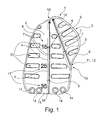
- FIG. 1 a first embodiment of a Fernhöhlenabdeckgitters 1 according to the invention is shown.
- the orbital cover grid is designed as an "orbita mesh". It has a multiply curved / curved / curved main body 2.
- the main body 2 has on its outside a substantially circumferential / closed outer end edge / skirting 3.
- An underside of the orbital cover grid 1, in particular of the main body 2 and the end edge / skirt 3, is designed to be patient-specific.
- the internal and external structure is patient-specific.
- the internal matrix of the main body and the material used, for example a titanium alloy, is adapted to the adjoining patient-specific anatomical region in terms of bending stiffness and / or modulus of elasticity, preferably as closely as possible copied.
- the orbital masking grid 1 can be adapted specifically to the bone or sockets forming the eye socket.
- the top of the implant / orbital cover grille 1 is provided with the reference numeral 4. On this top 4, a first channel 5 and a second channel 6 trained. Both channels 5 and 6 are linear and are visually and tactilely recognizable. Each channel 5 or 6 defines an insertion vector. Each channel 5 and 6 each have two channel walls 7, which protrude orthogonally from the top 4, wherein between the two channel walls 7 of a channel 5 and 6, a channel bottom 8 is defined.
- a navigation stop 9 is present in / on / on the channel bottom 8 .
- two navigation stops 9 are provided, whereas in the second channel 6 only a single navigation stop 9 is provided.
- perforations or slots / passage slots 10 are kept in the manner of through holes. They have an elongated form. They each extend orthogonally to the terminal edge / skirt 3, which is formed by a cord 11, which has a nearly circular, elliptical or rounded cross-section. The cord therefore acts atraumatic.
- An exact tear path region 13 is also physically designed and predefined.
- the through holes 14 There are four through holes 14 held in a front edge 15 of the orbital cover grid 1.
- the through holes 14 define a drilling vector, or follow a predetermined Bohrvektor.
- the drilling vector is operator specific.
- the drill vector is obliquely on the top 4 and / or bottom of the main body 2 of the orbital masking grid 1.
- screws can be introduced, which can be anchored in the bone.
- a tip portion 16 is present at the opposite end of the main body 2. There, inside or outside the material forming the main body 2, the insertion vectors meet.
- a length scale 17 formed by numbers such as the numbers 15, 25, and 35 is formed on the left side of the first channel 5 beginning / following from the tip portion 16.
- the length scale 17 is designed in the manner of a (calibrated) ruler.
- the slots / passageways 10 form a drainage system.
- a critical area is predefined in terms of the visual canal / optic nerve.
- the insertion vector on which the channels 5 and 6 are based is provided with the reference numeral 18.
- the channels 5 and 6 are not only advantageous in implanting, so inserting the Augenhöhlenabdeckgitters 1, but also in the subsequent control of the implanting process. This enables a quality assurance procedure without injuring the patient.
- An adjustment of the real position of the eye socket cover grid 1 in the patient with a desired position on the computer is always easy to carry out. Postoperative control of the situation is facilitated. Matching with the 3D dataset as planned was enabled.
- the patient can be provided with a reference point and read into the computer. In particular, there are three reference points.
- the channels 5 and 6 then act as a guide with intermediate points / depressions. The guide path is thus the first channel 5 or the second channel 6 and the intermediate points / depressions are then the navigation stops 9.
- the channels 5 and 6 thus form a physical double contour / line for improved guidance of a control instrument.
- the tip region 16 may be designed in the manner of an inverted snow pusher-like tip, ie form a curvature protruding from the optic nerve, so that sprouting of the eye muscle or mechanical irritation / perforation of the optic nerve is excluded / avoided. Perforations, such as the slots / passageways 10 are also deliberately oriented orthogonal to a patient-specific vector, in particular to the insertion vector 18.
- the tip portion 16 is prepared for abutment with the bone.
- the edge, in particular formed by the end edge / skirt 3, can be planned so that the implant forms a supernatant, which can be brought into contact with the bone and / or provides a handle for the surgeon.
- a secondary model can be applied to a primary model.
- the secondary model can be a conglomerate of different layers and shapes. Separating the implant from the 3D model is desirable.
- the implant can then be a model, for example in the form of a standardized 3D dataset form, for example in the form of an STL dataset.
- the secondary model can be a "BMP template", whereby JPEG, TIFF and similar formats are also possible.
- the material of the orbital masking grid 1 also absorbable material can be used.
Landscapes
- Health & Medical Sciences (AREA)
- Orthopedic Medicine & Surgery (AREA)
- Life Sciences & Earth Sciences (AREA)
- Surgery (AREA)
- Engineering & Computer Science (AREA)
- Animal Behavior & Ethology (AREA)
- Veterinary Medicine (AREA)
- Public Health (AREA)
- Biomedical Technology (AREA)
- Heart & Thoracic Surgery (AREA)
- General Health & Medical Sciences (AREA)
- Medical Informatics (AREA)
- Nuclear Medicine, Radiotherapy & Molecular Imaging (AREA)
- Neurology (AREA)
- Molecular Biology (AREA)
- Transplantation (AREA)
- Vascular Medicine (AREA)
- Oral & Maxillofacial Surgery (AREA)
- Cardiology (AREA)
- Neurosurgery (AREA)
- Manufacturing & Machinery (AREA)
- Prostheses (AREA)
- Orthopedics, Nursing, And Contraception (AREA)
Priority Applications (2)
| Application Number | Priority Date | Filing Date | Title |
|---|---|---|---|
| ES15163021T ES2561678T3 (es) | 2014-06-11 | 2014-06-11 | Procedimiento para la fabricación de una rejilla de protección de órbita ocular específica para el paciente |
| EP15163021.7A EP2954864B1 (fr) | 2014-06-11 | 2014-06-11 | Procédé de fabrication d'une grille de recouvrement des orbites spécifique au patient |
Applications Claiming Priority (2)
| Application Number | Priority Date | Filing Date | Title |
|---|---|---|---|
| EP14172026.8A EP2954863B1 (fr) | 2014-06-11 | 2014-06-11 | Procédé de fabrication d'une grille de recouvrement des orbites spécifique au patient et grille de recouvrement des orbites spécifique au patient |
| EP15163021.7A EP2954864B1 (fr) | 2014-06-11 | 2014-06-11 | Procédé de fabrication d'une grille de recouvrement des orbites spécifique au patient |
Related Parent Applications (2)
| Application Number | Title | Priority Date | Filing Date |
|---|---|---|---|
| EP14172026.8A Division EP2954863B1 (fr) | 2014-06-11 | 2014-06-11 | Procédé de fabrication d'une grille de recouvrement des orbites spécifique au patient et grille de recouvrement des orbites spécifique au patient |
| EP14172026.8A Division-Into EP2954863B1 (fr) | 2014-06-11 | 2014-06-11 | Procédé de fabrication d'une grille de recouvrement des orbites spécifique au patient et grille de recouvrement des orbites spécifique au patient |
Publications (2)
| Publication Number | Publication Date |
|---|---|
| EP2954864A1 true EP2954864A1 (fr) | 2015-12-16 |
| EP2954864B1 EP2954864B1 (fr) | 2019-08-21 |
Family
ID=50943125
Family Applications (2)
| Application Number | Title | Priority Date | Filing Date |
|---|---|---|---|
| EP15163021.7A Active EP2954864B1 (fr) | 2014-06-11 | 2014-06-11 | Procédé de fabrication d'une grille de recouvrement des orbites spécifique au patient |
| EP14172026.8A Active EP2954863B1 (fr) | 2014-06-11 | 2014-06-11 | Procédé de fabrication d'une grille de recouvrement des orbites spécifique au patient et grille de recouvrement des orbites spécifique au patient |
Family Applications After (1)
| Application Number | Title | Priority Date | Filing Date |
|---|---|---|---|
| EP14172026.8A Active EP2954863B1 (fr) | 2014-06-11 | 2014-06-11 | Procédé de fabrication d'une grille de recouvrement des orbites spécifique au patient et grille de recouvrement des orbites spécifique au patient |
Country Status (6)
| Country | Link |
|---|---|
| US (1) | US10561452B2 (fr) |
| EP (2) | EP2954864B1 (fr) |
| CN (1) | CN106456220B (fr) |
| BR (1) | BR112016028627B1 (fr) |
| ES (2) | ES2561678T3 (fr) |
| WO (1) | WO2015188962A1 (fr) |
Families Citing this family (1)
| Publication number | Priority date | Publication date | Assignee | Title |
|---|---|---|---|---|
| EP4729300A2 (fr) * | 2020-05-29 | 2026-04-22 | Materialise NV | Implants avec repères de navigation |
Citations (5)
| Publication number | Priority date | Publication date | Assignee | Title |
|---|---|---|---|---|
| DE19746396A1 (de) | 1997-10-21 | 1999-05-06 | Howmedica Leibinger Gmbh & Co | Gitter für die Fixierung von Knochenteilen oder für die Überbrückung von Knochenfehlstellen |
| US20030109784A1 (en) | 2000-05-10 | 2003-06-12 | Loh Kwok Weng Leonard | Method of producing profiled sheets as prosthesis |
| EP1965735B1 (fr) | 2005-12-29 | 2009-09-02 | Synthes GmbH | Implant à utiliser comme remplacement de fond d'orbite |
| US20110319745A1 (en) | 2010-06-29 | 2011-12-29 | Frey George A | Patient Matching Surgical Guide and Method for Using the Same |
| US20120010711A1 (en) | 2010-06-11 | 2012-01-12 | Antonyshyn Oleh | Method of forming patient-specific implant |
Family Cites Families (13)
| Publication number | Priority date | Publication date | Assignee | Title |
|---|---|---|---|---|
| US5139497A (en) * | 1991-11-25 | 1992-08-18 | Timesh, Inc. | Orbital repair implant |
| US5383931A (en) * | 1992-01-03 | 1995-01-24 | Synthes (U.S.A.) | Resorbable implantable device for the reconstruction of the orbit of the human skull |
| US5743913A (en) * | 1997-04-02 | 1998-04-28 | Wellisz; Tadeusz Z. | Readily expansible bone fixation plate |
| EP2081494B1 (fr) | 2006-11-16 | 2018-07-11 | Vanderbilt University | Système et procédé de compensation de déformation d'organe |
| EP2030596B1 (fr) * | 2007-08-27 | 2019-11-27 | Medartis Holding AG | Implant destiné au traitement d'os. |
| AU2009319753B2 (en) * | 2008-11-26 | 2013-11-14 | Anew Iol Technologies, Inc. | Haptic devices for intraocular lens |
| CN101637414B (zh) * | 2009-08-27 | 2011-04-27 | 北京吉马飞科技发展有限公司 | 眼眶、颧骨及上颌骨的整体修复支架及制造方法 |
| US8740984B2 (en) | 2009-10-06 | 2014-06-03 | Microport Orthopedics Holdings Inc. | Tibial implant base |
| TWM417131U (en) | 2010-12-24 | 2011-12-01 | Univ Nat Taiwan Science Tech | Improving bony plate structure |
| US8933935B2 (en) * | 2011-11-10 | 2015-01-13 | 7D Surgical Inc. | Method of rendering and manipulating anatomical images on mobile computing device |
| CN203619658U (zh) * | 2013-09-18 | 2014-06-04 | 天津康立尔生物科技有限公司 | 一种眼眶眶底板 |
| CN203619652U (zh) * | 2013-09-18 | 2014-06-04 | 天津康立尔生物科技有限公司 | 一种可弯曲侧眼眶接骨板 |
| EP2923676A1 (fr) * | 2014-03-25 | 2015-09-30 | Karl Leibinger Medizintechnik Gmbh & Co. Kg | Grille de recouvrement des orbites comprenant des évidements longitudinaux suivant les contours extérieurs |
-
2014
- 2014-06-11 EP EP15163021.7A patent/EP2954864B1/fr active Active
- 2014-06-11 EP EP14172026.8A patent/EP2954863B1/fr active Active
- 2014-06-11 ES ES15163021T patent/ES2561678T3/es active Active
- 2014-06-11 ES ES14172026.8T patent/ES2634868T3/es active Active
-
2015
- 2015-04-09 US US15/316,728 patent/US10561452B2/en active Active
- 2015-04-09 WO PCT/EP2015/057745 patent/WO2015188962A1/fr not_active Ceased
- 2015-04-09 CN CN201580030922.XA patent/CN106456220B/zh active Active
- 2015-04-09 BR BR112016028627-8A patent/BR112016028627B1/pt active IP Right Grant
Patent Citations (5)
| Publication number | Priority date | Publication date | Assignee | Title |
|---|---|---|---|---|
| DE19746396A1 (de) | 1997-10-21 | 1999-05-06 | Howmedica Leibinger Gmbh & Co | Gitter für die Fixierung von Knochenteilen oder für die Überbrückung von Knochenfehlstellen |
| US20030109784A1 (en) | 2000-05-10 | 2003-06-12 | Loh Kwok Weng Leonard | Method of producing profiled sheets as prosthesis |
| EP1965735B1 (fr) | 2005-12-29 | 2009-09-02 | Synthes GmbH | Implant à utiliser comme remplacement de fond d'orbite |
| US20120010711A1 (en) | 2010-06-11 | 2012-01-12 | Antonyshyn Oleh | Method of forming patient-specific implant |
| US20110319745A1 (en) | 2010-06-29 | 2011-12-29 | Frey George A | Patient Matching Surgical Guide and Method for Using the Same |
Also Published As
| Publication number | Publication date |
|---|---|
| CN106456220A (zh) | 2017-02-22 |
| ES2634868T3 (es) | 2017-09-29 |
| ES2561678T3 (es) | 2020-03-24 |
| EP2954864B1 (fr) | 2019-08-21 |
| US20180185074A1 (en) | 2018-07-05 |
| CN106456220B (zh) | 2019-12-13 |
| BR112016028627A2 (pt) | 2017-08-22 |
| WO2015188962A1 (fr) | 2015-12-17 |
| BR112016028627A8 (pt) | 2021-05-11 |
| EP2954863B1 (fr) | 2017-05-17 |
| US10561452B2 (en) | 2020-02-18 |
| EP2954863A1 (fr) | 2015-12-16 |
| BR112016028627B1 (pt) | 2022-06-21 |
| ES2561678T1 (es) | 2016-02-29 |
Similar Documents
| Publication | Publication Date | Title |
|---|---|---|
| DE202014011170U1 (de) | Augenhöhlenabdeckgitter mit geschwungenem Hauptkörper | |
| DE69416588T2 (de) | Intervertebrale scheibenprothese | |
| EP2030596B1 (fr) | Implant destiné au traitement d'os. | |
| DE102009028503B4 (de) | Resektionsschablone zur Resektion von Knochen, Verfahren zur Herstellung einer solchen Resektionsschablone und Operationsset zur Durchführung von Kniegelenk-Operationen | |
| DE69225431T2 (de) | Prosthetisches Implantat | |
| DE60301901T2 (de) | Apparat zur Fusion benachbarter Knochenstrukturen | |
| EP2001381B1 (fr) | Procede et dispositif de fabrication d'un implant plat preforme en correspondance a une forme anatomique de consigne pour le corps humain ou le corps d'un animal | |
| EP3122290B1 (fr) | Grille de recouvrement des orbites comprenant des évidements longitudinaux suivant les contours extérieurs | |
| EP3393376B1 (fr) | Implant pour une consolidation osseuse avec trou prédéfini de vecteur de perçage et plaque d'adhésion pour remplacement maxillaire ainsi que procédé de fabrication d'un implant | |
| DE102014008476A1 (de) | Herstellung einer Komponente zur Züchtung eines Gelenkflächenimplantats, Züchtung und Implantation eines Gelenkflächenimplantats | |
| DE69634255T2 (de) | Elemente für gelenkprothese und verfahren zu deren herstellung | |
| DE102014208283A1 (de) | Vorrichtung zum Anbringen eines Positionierungsmittels an einem Knochen eines Patienten, Vorrichtung zum Bearbeiten eines Knochens eines Patienten und Hüftimplantatsystem | |
| DE102019118134B4 (de) | Verfahren zur Herstellung einer Abdeckvorrichtung für eine Knochendefektstelle; Abdeckvorrichtung für eine Knochendefektstelle; | |
| EP2954864B1 (fr) | Procédé de fabrication d'une grille de recouvrement des orbites spécifique au patient | |
| EP3258889B1 (fr) | Orthèse et procédé de production d'une orthèse | |
| EP1744693B1 (fr) | Modele en trois dimensions d'un crane d'enfant humain grandeur nature | |
| DE102015006154B4 (de) | Vorrichtung zur Abdeckung und/oder Rekonstruktion einer Knochendefektstelle; Verfahren zur Herstellung eines Aufsatzes einer Abdeckvorrichtung für eine Knochendefektstelle | |
| DE202011109986U1 (de) | Nasenwandimplantat und Operationsset zur Korrektur einer Knorpelschwäche der menschlichen Nase | |
| DE102004032675B4 (de) | Prüfhilfe zur Überprüfung des Formenschlusses zwischen der Außenkontur eines präparierten Restgelenkkopfes und der Innenoberfläche der Prüfhilfe selbst | |
| DE102019114314A1 (de) | Handgelenksendoprothese | |
| EP2818137B1 (fr) | Prothèse d'osselet avec marqueur CT ou MRT | |
| DE202005021705U1 (de) | Vorrichtung zum Herstellen von Wirbelsäulen-Implantaten | |
| DE202023104371U1 (de) | Einteilige Endoprothese im Schwellkörperbereich mit intraoperativem Längenverstellsystem und Tragekomfortsystem | |
| DE19933382A1 (de) | Füllimplantat für Knorpel- und Knochendefekte in einem Gelenk | |
| DE1960087A1 (de) | Kuenstliches Gelenk fuer human- und tiermedizinische Verwendung |
Legal Events
| Date | Code | Title | Description |
|---|---|---|---|
| PUAI | Public reference made under article 153(3) epc to a published international application that has entered the european phase |
Free format text: ORIGINAL CODE: 0009012 |
|
| 17P | Request for examination filed |
Effective date: 20150819 |
|
| AC | Divisional application: reference to earlier application |
Ref document number: 2954863 Country of ref document: EP Kind code of ref document: P |
|
| AK | Designated contracting states |
Kind code of ref document: A1 Designated state(s): AL AT BE BG CH CY CZ DE DK EE ES FI FR GB GR HR HU IE IS IT LI LT LU LV MC MK MT NL NO PL PT RO RS SE SI SK SM TR |
|
| AX | Request for extension of the european patent |
Extension state: BA ME |
|
| REG | Reference to a national code |
Ref country code: FR Ref legal event code: EL |
|
| RBV | Designated contracting states (corrected) |
Designated state(s): AL AT BE BG CH CY CZ DE DK EE ES FI FR GB GR HR HU IE IS IT LI LT LU LV MC MK MT NL NO PL PT RO RS SE SI SK SM TR |
|
| STAA | Information on the status of an ep patent application or granted ep patent |
Free format text: STATUS: EXAMINATION IS IN PROGRESS |
|
| 17Q | First examination report despatched |
Effective date: 20171124 |
|
| RIC1 | Information provided on ipc code assigned before grant |
Ipc: A61B 17/56 20060101ALI20190124BHEP Ipc: A61F 2/30 20060101ALI20190124BHEP Ipc: A61B 17/80 20060101AFI20190124BHEP Ipc: A61B 90/00 20160101ALI20190124BHEP Ipc: A61F 2/28 20060101ALI20190124BHEP |
|
| GRAP | Despatch of communication of intention to grant a patent |
Free format text: ORIGINAL CODE: EPIDOSNIGR1 |
|
| STAA | Information on the status of an ep patent application or granted ep patent |
Free format text: STATUS: GRANT OF PATENT IS INTENDED |
|
| INTG | Intention to grant announced |
Effective date: 20190304 |
|
| GRAS | Grant fee paid |
Free format text: ORIGINAL CODE: EPIDOSNIGR3 |
|
| GRAA | (expected) grant |
Free format text: ORIGINAL CODE: 0009210 |
|
| STAA | Information on the status of an ep patent application or granted ep patent |
Free format text: STATUS: THE PATENT HAS BEEN GRANTED |
|
| AC | Divisional application: reference to earlier application |
Ref document number: 2954863 Country of ref document: EP Kind code of ref document: P |
|
| AK | Designated contracting states |
Kind code of ref document: B1 Designated state(s): AL AT BE BG CH CY CZ DE DK EE ES FI FR GB GR HR HU IE IS IT LI LT LU LV MC MK MT NL NO PL PT RO RS SE SI SK SM TR |
|
| REG | Reference to a national code |
Ref country code: GB Ref legal event code: FG4D Free format text: NOT ENGLISH |
|
| REG | Reference to a national code |
Ref country code: CH Ref legal event code: EP |
|
| REG | Reference to a national code |
Ref country code: DE Ref legal event code: R096 Ref document number: 502014012481 Country of ref document: DE |
|
| REG | Reference to a national code |
Ref country code: AT Ref legal event code: REF Ref document number: 1168798 Country of ref document: AT Kind code of ref document: T Effective date: 20190915 |
|
| REG | Reference to a national code |
Ref country code: IE Ref legal event code: FG4D Free format text: LANGUAGE OF EP DOCUMENT: GERMAN |
|
| REG | Reference to a national code |
Ref country code: LT Ref legal event code: MG4D |
|
| REG | Reference to a national code |
Ref country code: NL Ref legal event code: MP Effective date: 20190821 |
|
| PG25 | Lapsed in a contracting state [announced via postgrant information from national office to epo] |
Ref country code: NO Free format text: LAPSE BECAUSE OF FAILURE TO SUBMIT A TRANSLATION OF THE DESCRIPTION OR TO PAY THE FEE WITHIN THE PRESCRIBED TIME-LIMIT Effective date: 20191121 Ref country code: BG Free format text: LAPSE BECAUSE OF FAILURE TO SUBMIT A TRANSLATION OF THE DESCRIPTION OR TO PAY THE FEE WITHIN THE PRESCRIBED TIME-LIMIT Effective date: 20191121 Ref country code: SE Free format text: LAPSE BECAUSE OF FAILURE TO SUBMIT A TRANSLATION OF THE DESCRIPTION OR TO PAY THE FEE WITHIN THE PRESCRIBED TIME-LIMIT Effective date: 20190821 Ref country code: NL Free format text: LAPSE BECAUSE OF FAILURE TO SUBMIT A TRANSLATION OF THE DESCRIPTION OR TO PAY THE FEE WITHIN THE PRESCRIBED TIME-LIMIT Effective date: 20190821 Ref country code: LT Free format text: LAPSE BECAUSE OF FAILURE TO SUBMIT A TRANSLATION OF THE DESCRIPTION OR TO PAY THE FEE WITHIN THE PRESCRIBED TIME-LIMIT Effective date: 20190821 Ref country code: PT Free format text: LAPSE BECAUSE OF FAILURE TO SUBMIT A TRANSLATION OF THE DESCRIPTION OR TO PAY THE FEE WITHIN THE PRESCRIBED TIME-LIMIT Effective date: 20191223 Ref country code: HR Free format text: LAPSE BECAUSE OF FAILURE TO SUBMIT A TRANSLATION OF THE DESCRIPTION OR TO PAY THE FEE WITHIN THE PRESCRIBED TIME-LIMIT Effective date: 20190821 Ref country code: FI Free format text: LAPSE BECAUSE OF FAILURE TO SUBMIT A TRANSLATION OF THE DESCRIPTION OR TO PAY THE FEE WITHIN THE PRESCRIBED TIME-LIMIT Effective date: 20190821 |
|
| PG25 | Lapsed in a contracting state [announced via postgrant information from national office to epo] |
Ref country code: AL Free format text: LAPSE BECAUSE OF FAILURE TO SUBMIT A TRANSLATION OF THE DESCRIPTION OR TO PAY THE FEE WITHIN THE PRESCRIBED TIME-LIMIT Effective date: 20190821 Ref country code: LV Free format text: LAPSE BECAUSE OF FAILURE TO SUBMIT A TRANSLATION OF THE DESCRIPTION OR TO PAY THE FEE WITHIN THE PRESCRIBED TIME-LIMIT Effective date: 20190821 Ref country code: IS Free format text: LAPSE BECAUSE OF FAILURE TO SUBMIT A TRANSLATION OF THE DESCRIPTION OR TO PAY THE FEE WITHIN THE PRESCRIBED TIME-LIMIT Effective date: 20191221 Ref country code: GR Free format text: LAPSE BECAUSE OF FAILURE TO SUBMIT A TRANSLATION OF THE DESCRIPTION OR TO PAY THE FEE WITHIN THE PRESCRIBED TIME-LIMIT Effective date: 20191122 Ref country code: RS Free format text: LAPSE BECAUSE OF FAILURE TO SUBMIT A TRANSLATION OF THE DESCRIPTION OR TO PAY THE FEE WITHIN THE PRESCRIBED TIME-LIMIT Effective date: 20190821 |
|
| REG | Reference to a national code |
Ref country code: ES Ref legal event code: FG2A Ref document number: 2561678 Country of ref document: ES Kind code of ref document: T3 Effective date: 20200324 |
|
| PG25 | Lapsed in a contracting state [announced via postgrant information from national office to epo] |
Ref country code: TR Free format text: LAPSE BECAUSE OF FAILURE TO SUBMIT A TRANSLATION OF THE DESCRIPTION OR TO PAY THE FEE WITHIN THE PRESCRIBED TIME-LIMIT Effective date: 20190821 |
|
| PG25 | Lapsed in a contracting state [announced via postgrant information from national office to epo] |
Ref country code: RO Free format text: LAPSE BECAUSE OF FAILURE TO SUBMIT A TRANSLATION OF THE DESCRIPTION OR TO PAY THE FEE WITHIN THE PRESCRIBED TIME-LIMIT Effective date: 20190821 Ref country code: EE Free format text: LAPSE BECAUSE OF FAILURE TO SUBMIT A TRANSLATION OF THE DESCRIPTION OR TO PAY THE FEE WITHIN THE PRESCRIBED TIME-LIMIT Effective date: 20190821 Ref country code: PL Free format text: LAPSE BECAUSE OF FAILURE TO SUBMIT A TRANSLATION OF THE DESCRIPTION OR TO PAY THE FEE WITHIN THE PRESCRIBED TIME-LIMIT Effective date: 20190821 Ref country code: DK Free format text: LAPSE BECAUSE OF FAILURE TO SUBMIT A TRANSLATION OF THE DESCRIPTION OR TO PAY THE FEE WITHIN THE PRESCRIBED TIME-LIMIT Effective date: 20190821 |
|
| PG25 | Lapsed in a contracting state [announced via postgrant information from national office to epo] |
Ref country code: IS Free format text: LAPSE BECAUSE OF FAILURE TO SUBMIT A TRANSLATION OF THE DESCRIPTION OR TO PAY THE FEE WITHIN THE PRESCRIBED TIME-LIMIT Effective date: 20200224 Ref country code: SM Free format text: LAPSE BECAUSE OF FAILURE TO SUBMIT A TRANSLATION OF THE DESCRIPTION OR TO PAY THE FEE WITHIN THE PRESCRIBED TIME-LIMIT Effective date: 20190821 Ref country code: SK Free format text: LAPSE BECAUSE OF FAILURE TO SUBMIT A TRANSLATION OF THE DESCRIPTION OR TO PAY THE FEE WITHIN THE PRESCRIBED TIME-LIMIT Effective date: 20190821 Ref country code: CZ Free format text: LAPSE BECAUSE OF FAILURE TO SUBMIT A TRANSLATION OF THE DESCRIPTION OR TO PAY THE FEE WITHIN THE PRESCRIBED TIME-LIMIT Effective date: 20190821 |
|
| REG | Reference to a national code |
Ref country code: DE Ref legal event code: R097 Ref document number: 502014012481 Country of ref document: DE |
|
| PLBE | No opposition filed within time limit |
Free format text: ORIGINAL CODE: 0009261 |
|
| STAA | Information on the status of an ep patent application or granted ep patent |
Free format text: STATUS: NO OPPOSITION FILED WITHIN TIME LIMIT |
|
| PG2D | Information on lapse in contracting state deleted |
Ref country code: IS |
|
| 26N | No opposition filed |
Effective date: 20200603 |
|
| PG25 | Lapsed in a contracting state [announced via postgrant information from national office to epo] |
Ref country code: SI Free format text: LAPSE BECAUSE OF FAILURE TO SUBMIT A TRANSLATION OF THE DESCRIPTION OR TO PAY THE FEE WITHIN THE PRESCRIBED TIME-LIMIT Effective date: 20190821 |
|
| PG25 | Lapsed in a contracting state [announced via postgrant information from national office to epo] |
Ref country code: MC Free format text: LAPSE BECAUSE OF FAILURE TO SUBMIT A TRANSLATION OF THE DESCRIPTION OR TO PAY THE FEE WITHIN THE PRESCRIBED TIME-LIMIT Effective date: 20190821 |
|
| REG | Reference to a national code |
Ref country code: CH Ref legal event code: PL |
|
| PG25 | Lapsed in a contracting state [announced via postgrant information from national office to epo] |
Ref country code: LU Free format text: LAPSE BECAUSE OF NON-PAYMENT OF DUE FEES Effective date: 20200611 |
|
| REG | Reference to a national code |
Ref country code: BE Ref legal event code: MM Effective date: 20200630 |
|
| PG25 | Lapsed in a contracting state [announced via postgrant information from national office to epo] |
Ref country code: IE Free format text: LAPSE BECAUSE OF NON-PAYMENT OF DUE FEES Effective date: 20200611 Ref country code: CH Free format text: LAPSE BECAUSE OF NON-PAYMENT OF DUE FEES Effective date: 20200630 Ref country code: LI Free format text: LAPSE BECAUSE OF NON-PAYMENT OF DUE FEES Effective date: 20200630 |
|
| PG25 | Lapsed in a contracting state [announced via postgrant information from national office to epo] |
Ref country code: BE Free format text: LAPSE BECAUSE OF NON-PAYMENT OF DUE FEES Effective date: 20200630 |
|
| REG | Reference to a national code |
Ref country code: AT Ref legal event code: MM01 Ref document number: 1168798 Country of ref document: AT Kind code of ref document: T Effective date: 20200611 |
|
| PG25 | Lapsed in a contracting state [announced via postgrant information from national office to epo] |
Ref country code: AT Free format text: LAPSE BECAUSE OF NON-PAYMENT OF DUE FEES Effective date: 20200611 |
|
| PG25 | Lapsed in a contracting state [announced via postgrant information from national office to epo] |
Ref country code: MT Free format text: LAPSE BECAUSE OF FAILURE TO SUBMIT A TRANSLATION OF THE DESCRIPTION OR TO PAY THE FEE WITHIN THE PRESCRIBED TIME-LIMIT Effective date: 20190821 Ref country code: CY Free format text: LAPSE BECAUSE OF FAILURE TO SUBMIT A TRANSLATION OF THE DESCRIPTION OR TO PAY THE FEE WITHIN THE PRESCRIBED TIME-LIMIT Effective date: 20190821 |
|
| PG25 | Lapsed in a contracting state [announced via postgrant information from national office to epo] |
Ref country code: MK Free format text: LAPSE BECAUSE OF FAILURE TO SUBMIT A TRANSLATION OF THE DESCRIPTION OR TO PAY THE FEE WITHIN THE PRESCRIBED TIME-LIMIT Effective date: 20190821 |
|
| REG | Reference to a national code |
Ref country code: DE Ref legal event code: R082 Ref document number: 502014012481 Country of ref document: DE Ref country code: DE Ref legal event code: R081 Ref document number: 502014012481 Country of ref document: DE Owner name: KARL LEIBINGER ASSET MANAGEMENT GMBH & CO. KG, DE Free format text: FORMER OWNER: KARL LEIBINGER MEDIZINTECHNIK GMBH & CO. KG, 78570 MUEHLHEIM, DE |
|
| REG | Reference to a national code |
Ref country code: GB Ref legal event code: 732E Free format text: REGISTERED BETWEEN 20241031 AND 20241106 |
|
| REG | Reference to a national code |
Ref country code: ES Ref legal event code: PC2A Owner name: KARL LEIBINGER ASSET MANAGEMENT GMBH & CO. KG Effective date: 20241125 |
|
| PGFP | Annual fee paid to national office [announced via postgrant information from national office to epo] |
Ref country code: DE Payment date: 20250618 Year of fee payment: 12 |
|
| PGFP | Annual fee paid to national office [announced via postgrant information from national office to epo] |
Ref country code: GB Payment date: 20250620 Year of fee payment: 12 |
|
| PGFP | Annual fee paid to national office [announced via postgrant information from national office to epo] |
Ref country code: FR Payment date: 20250618 Year of fee payment: 12 |
|
| PGFP | Annual fee paid to national office [announced via postgrant information from national office to epo] |
Ref country code: ES Payment date: 20250718 Year of fee payment: 12 |
|
| PGFP | Annual fee paid to national office [announced via postgrant information from national office to epo] |
Ref country code: IT Payment date: 20250630 Year of fee payment: 12 |