EP2954960A2 - Einheit zur desinfektion und/oder reinigung von leitungen, insbesondere von trinkwasserleitungen, sowie verfahren zur desinfektion und/oder reinigung solcher leitungen - Google Patents
Einheit zur desinfektion und/oder reinigung von leitungen, insbesondere von trinkwasserleitungen, sowie verfahren zur desinfektion und/oder reinigung solcher leitungen Download PDFInfo
- Publication number
- EP2954960A2 EP2954960A2 EP15001686.3A EP15001686A EP2954960A2 EP 2954960 A2 EP2954960 A2 EP 2954960A2 EP 15001686 A EP15001686 A EP 15001686A EP 2954960 A2 EP2954960 A2 EP 2954960A2
- Authority
- EP
- European Patent Office
- Prior art keywords
- container
- unit according
- connecting piece
- chemical
- cleaning
- Prior art date
- Legal status (The legal status is an assumption and is not a legal conclusion. Google has not performed a legal analysis and makes no representation as to the accuracy of the status listed.)
- Granted
Links
Images
Classifications
-
- B—PERFORMING OPERATIONS; TRANSPORTING
- B08—CLEANING
- B08B—CLEANING IN GENERAL; PREVENTION OF FOULING IN GENERAL
- B08B9/00—Cleaning hollow articles by methods or apparatus specially adapted thereto
- B08B9/02—Cleaning pipes or tubes or systems of pipes or tubes
- B08B9/027—Cleaning the internal surfaces; Removal of blockages
- B08B9/032—Cleaning the internal surfaces; Removal of blockages by the mechanical action of a moving fluid, e.g. by flushing
- B08B9/0321—Cleaning the internal surfaces; Removal of blockages by the mechanical action of a moving fluid, e.g. by flushing using pressurised, pulsating or purging fluid
- B08B9/0328—Cleaning the internal surfaces; Removal of blockages by the mechanical action of a moving fluid, e.g. by flushing using pressurised, pulsating or purging fluid by purging the pipe with a gas or a mixture of gas and liquid
-
- B—PERFORMING OPERATIONS; TRANSPORTING
- B01—PHYSICAL OR CHEMICAL PROCESSES OR APPARATUS IN GENERAL
- B01F—MIXING, e.g. DISSOLVING, EMULSIFYING OR DISPERSING
- B01F23/00—Mixing according to the phases to be mixed, e.g. dispersing or emulsifying
- B01F23/40—Mixing liquids with liquids; Emulsifying
- B01F23/45—Mixing liquids with liquids; Emulsifying using flow mixing
- B01F23/451—Mixing liquids with liquids; Emulsifying using flow mixing by injecting one liquid into another
-
- B—PERFORMING OPERATIONS; TRANSPORTING
- B01—PHYSICAL OR CHEMICAL PROCESSES OR APPARATUS IN GENERAL
- B01F—MIXING, e.g. DISSOLVING, EMULSIFYING OR DISPERSING
- B01F25/00—Flow mixers; Mixers for falling materials, e.g. solid particles
- B01F25/30—Injector mixers
- B01F25/31—Injector mixers in conduits or tubes through which the main component flows
- B01F25/313—Injector mixers in conduits or tubes through which the main component flows wherein additional components are introduced in the centre of the conduit
-
- B—PERFORMING OPERATIONS; TRANSPORTING
- B01—PHYSICAL OR CHEMICAL PROCESSES OR APPARATUS IN GENERAL
- B01F—MIXING, e.g. DISSOLVING, EMULSIFYING OR DISPERSING
- B01F25/00—Flow mixers; Mixers for falling materials, e.g. solid particles
- B01F25/30—Injector mixers
- B01F25/31—Injector mixers in conduits or tubes through which the main component flows
- B01F25/316—Injector mixers in conduits or tubes through which the main component flows with containers for additional components fixed to the conduit
-
- B—PERFORMING OPERATIONS; TRANSPORTING
- B08—CLEANING
- B08B—CLEANING IN GENERAL; PREVENTION OF FOULING IN GENERAL
- B08B9/00—Cleaning hollow articles by methods or apparatus specially adapted thereto
- B08B9/02—Cleaning pipes or tubes or systems of pipes or tubes
- B08B9/027—Cleaning the internal surfaces; Removal of blockages
-
- C—CHEMISTRY; METALLURGY
- C11—ANIMAL OR VEGETABLE OILS, FATS, FATTY SUBSTANCES OR WAXES; FATTY ACIDS THEREFROM; DETERGENTS; CANDLES
- C11D—DETERGENT COMPOSITIONS; USE OF SINGLE SUBSTANCES AS DETERGENTS; SOAP OR SOAP-MAKING; RESIN SOAPS; RECOVERY OF GLYCEROL
- C11D3/00—Other compounding ingredients of detergent compositions covered in group C11D1/00
- C11D3/48—Medical, disinfecting agents, disinfecting, antibacterial, germicidal or antimicrobial compositions
-
- F—MECHANICAL ENGINEERING; LIGHTING; HEATING; WEAPONS; BLASTING
- F04—POSITIVE - DISPLACEMENT MACHINES FOR LIQUIDS; PUMPS FOR LIQUIDS OR ELASTIC FLUIDS
- F04F—PUMPING OF FLUID BY DIRECT CONTACT OF ANOTHER FLUID OR BY USING INERTIA OF FLUID TO BE PUMPED; SIPHONS
- F04F5/00—Jet pumps, i.e. devices in which flow is induced by pressure drop caused by velocity of another fluid flow
- F04F5/02—Jet pumps, i.e. devices in which flow is induced by pressure drop caused by velocity of another fluid flow the inducing fluid being liquid
- F04F5/10—Jet pumps, i.e. devices in which flow is induced by pressure drop caused by velocity of another fluid flow the inducing fluid being liquid displacing liquids, e.g. containing solids, or liquids and elastic fluids
-
- C—CHEMISTRY; METALLURGY
- C02—TREATMENT OF WATER, WASTE WATER, SEWAGE, OR SLUDGE
- C02F—TREATMENT OF WATER, WASTE WATER, SEWAGE, OR SLUDGE
- C02F1/00—Treatment of water, waste water, or sewage
- C02F1/68—Treatment of water, waste water, or sewage by addition of specified substances, e.g. trace elements, for ameliorating potable water
- C02F1/685—Devices for dosing the additives
- C02F1/686—Devices for dosing liquid additives
-
- C—CHEMISTRY; METALLURGY
- C02—TREATMENT OF WATER, WASTE WATER, SEWAGE, OR SLUDGE
- C02F—TREATMENT OF WATER, WASTE WATER, SEWAGE, OR SLUDGE
- C02F1/00—Treatment of water, waste water, or sewage
- C02F1/68—Treatment of water, waste water, or sewage by addition of specified substances, e.g. trace elements, for ameliorating potable water
- C02F1/685—Devices for dosing the additives
- C02F1/687—Devices for dosing solid compounds
-
- C—CHEMISTRY; METALLURGY
- C02—TREATMENT OF WATER, WASTE WATER, SEWAGE, OR SLUDGE
- C02F—TREATMENT OF WATER, WASTE WATER, SEWAGE, OR SLUDGE
- C02F1/00—Treatment of water, waste water, or sewage
- C02F1/72—Treatment of water, waste water, or sewage by oxidation
- C02F1/722—Oxidation by peroxides
-
- C—CHEMISTRY; METALLURGY
- C02—TREATMENT OF WATER, WASTE WATER, SEWAGE, OR SLUDGE
- C02F—TREATMENT OF WATER, WASTE WATER, SEWAGE, OR SLUDGE
- C02F2303/00—Specific treatment goals
- C02F2303/04—Disinfection
-
- C—CHEMISTRY; METALLURGY
- C02—TREATMENT OF WATER, WASTE WATER, SEWAGE, OR SLUDGE
- C02F—TREATMENT OF WATER, WASTE WATER, SEWAGE, OR SLUDGE
- C02F2307/00—Location of water treatment or water treatment device
- C02F2307/14—Treatment of water in water supply networks, e.g. to prevent bacterial growth
Definitions
- the invention relates to a unit for disinfecting and / or cleaning of lines, in particular drinking water lines, according to the preamble of claim 1 and a method for disinfecting and / or cleaning of lines, especially drinking water lines, according to the preamble of claim 14.
- the drinking water pipes are cleaned with water, if necessary with the addition of intermittent compressed air (compressed air surges).
- a treatment of drinking water pipes with a disinfectant may be required.
- any contamination of the drinking water installation that has occurred during installation or operation over the years is removed with pressure washers.
- water is flushed under pressure through the drinking water pipes.
- a corresponding chemical is added to the rinse water, which is mixed in a certain concentration of the drinking water.
- the drinking water is rinsed out again with the added chemical.
- all extraction points at the drinking water installation are opened one after the other until the disinfection chemical exits at the respective extraction point.
- the respective tapping points are closed, so that the chemical contained in the drinking water act on the drinking water pipes can.
- Typical exposure times are in the range up to 24 hours. After the exposure time, the sampling points are opened one after the other until no disinfection chemical can be detected on the expiring drinking water.
- the chemical is contained in a container which is connected to a compressed air tank of the compressed air sprayer. To discharge the chemical, the compressed air is introduced into the container, whereby the chemical is forced out of the container via a line. The addition of the chemical thus requires a compressed air source.
- the invention is based on the object, the generic unit and the generic method in such a way that a trouble-free, yet reliable disinfection and / or cleaning of the lines is guaranteed.
- the unit of the invention does not require compressed air to discharge the chemical contained in the container, but instead uses the water already used for the cleaning of the lines.
- the container has the connecting piece, which projects into the flow cross section of the pipe coupling through which water flows. This forms in the flow direction in front of the fitting in the pipe coupling a dynamic pressure. It causes a portion of the water to be forced into the container via the first line of the connection piece.
- On the chemical in the container thus acts a pressure through which it is pressed into the second line of the connector.
- the chemical exits downstream from the second line connector and is added to the water flowing through the pipe coupling.
- the unit thus does not require the discharge of the chemical in the container, no additional pressure source, so that easy handling during disinfection and / or cleaning process is achieved.
- the connector protrudes advantageous with an end part in the pipe coupling. Its cross section is larger than the cross section of the end part. This allows the water to flow past the end part through the pipe coupling. The end part of the connection piece generates the back pressure.
- the connector is provided with a support member which is placed on a neck of the container. This allows the container, when it is empty, simply take off and replace it with a new container.
- the support member is releasably connected to the neck of the container, so that a simple exchange is ensured.
- the handling is particularly facilitated by the fact that the support member of the connector is screwed onto the neck of the container.
- connection piece is provided with a diffuser part which has a smaller cross-section than the container in the region of the diffuser part.
- the pressurized water emerging from the first conduit initially strikes the diffuser part, through which it is then passed into the container interior.
- the water only hits the chemical in a targeted manner, ensuring undisturbed discharge of the chemical.
- the water flows between the diffuser part and the container wall down into the container interior.
- a uniform distribution of the water emerging from the first conduit is achieved in an advantageous manner when the diffuser part has a circular outline.
- the first conduit opens at a distance in front of the diffuser part in the peripheral surface of the neck.
- the diffuser part ensures that the water gets distributed evenly around the circumference down into the chemical.
- the second line opens into the end face of the approach, which projects into the interior of the container.
- a suction hose is connected, which extends to the bottom of the container and over which the chemical is pushed out by the pressurized water.
- the unit is advantageously provided with a pressure relief valve which can be connected to the pipe coupling. If the pressure in the system exceeds the permissible maximum value, the pressure limiting valve ensures that the water pressure does not rise above the specified value.
- the unit is advantageously provided with a non-return valve which is located in the flow direction behind the entry of the chemical into the water flowing through the pipe coupling.
- the cross section of the second pipe by at least one metering element.
- a metering screw with which the flow area of the second conduit can be adjusted infinitely sensitive.
- At least one detection indicator for the chemicals is added immediately before the beginning of the disinfection and / or cleaning of the disinfecting and / or cleaning chemical. It makes it easier for the installer to determine when the discharge of the water with the chemical occurs when the sampling point is open. Through the detection indicator, the installer receives a clear indication of when this is the case and he can close the sampling point.
- the detection indicator is added only immediately before the start of disinfection and / or cleaning, it is advantageously ensured that the detection indicator is not destroyed prematurely.
- H2O2 is used for disinfection or cleaning, which reacts very aggressively and would destroy added other chemicals over time.
- the detection indicator is added just before the disinfection / cleaning process, it is ensured that the detection indicator is not decomposed by aggressive chemicals during the disinfection / cleaning process.
- the detection indicator can be added in liquid form, but also in solid form be, for example in the form of granules, powders, tablets and the like.
- the unit is used for the disinfection of drinking water installations. Bacterial (microbial) contamination (contaminations) and deposits in drinking water installations endanger the quality of the drinking water.
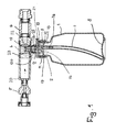
- a pressure relief valve 5 At the in Fig. 1 left end of the T-piece 4 is a pressure relief valve 5 and connected to the right end of a check valve 6.
- the pressure relief valve 5 is connected to a Connected to water pipe, through which water is supplied for cleaning the drinking water installation.
- the water flows through the pressure relief valve 5 and the check valve 6.
- a suction hose 7 through which the chemical is supplied to the flow head 3.
- the bottom 8 of the container 1 is formed curved inwards.
- the suction hose 7, which is flexible, is so long that it extends into the area next to the curved bottom 8 of the container 1.
- the flow head 3 has a support member 9 with which it sits on the neck 2 of the container 1.
- the support member 9 is cylindrical and provided with an internal thread 10, with which the support member 9 is screwed onto the provided with an external thread 11 neck 2 of the container.
- the support member 9 is sufficiently dimensionally stable, so that the flow head 3 can be securely screwed onto the neck 2.
- the support member 9 may be exemplified with a snap-on profile, with which it can be snapped onto a corresponding counter-profile on the neck 2.
- the connecting portion between the support member 9 and the neck 2 is formed dense, so that no chemical from the container 1 can inadvertently escape to the outside.
- To the support member includes a bottom 12, which is disc-shaped and protrudes from the center of a head piece 13 on which the T-piece 4 sits.
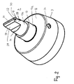
- the head piece 13 has, as is apparent Fig. 2 results in a subsequent to the bottom 12 threaded lower portion 13a, which merges via a paragraph in a smaller diameter upper part 13b.
- the lower part 13a has greater wall thickness than the upper part 13b. Both parts 13a, 13b are cylindrical and each have a smaller diameter than the bottom 12th
- the T-piece 4 is screwed onto the lower, thicker in the wall thickness portion 13a threaded, whereby a secure attachment of the container 1 on the tee 4 is ensured.
- end face 14 of the upper part 13b projects from an end portion 15 which extends diametrically with respect to the upper part 13b of the head piece 13 and the front side is closed.
- a lug 16 From the underside of the bottom 12 of the flow head 3 is centrally from a lug 16 from which is provided at the free end with a diffuser disk 17. It is designed as over the circumference of the neck 16 circumferential flange.
- the approach has 16 circular cross-section.
- the diffuser disk 17 is a radial flange with a circular outline. The diameter of the diffuser disk 17 is smaller than the inner diameter of the neck 2 of the container 1.
- the bore 19 opens against the inflow direction 20 of the water in the lateral surface 18 of the projection 16 opens with axial distance to the diffuser disc 17 in the side wall of the end portion 15th
- a bore 24 which receives a metering element 25.
- the bore 24 extends into the bore 21 (FIG. Fig. 1 ).
- the metering element 25 is so long that it extends into the bore 21st can reach. With the metering element 25, the flow cross-section for the disinfectant through the bore 21 can be adjusted sensitively.
- FIG. 1 The lower end of the bore 21 is widened in diameter and receives a holding element 26, which is formed as a continuous sleeve and is held firmly in the extension 16 with its enlarged head. On the holding element 26 of the flexible suction hose 7 is pushed.
- the flow head 3 is advantageously made in one piece from plastic. With the support member 9, the flow head 3 can be easily mounted on the container 1 or easily remove it. In the installed position, the end portion 15 of the flow head 13 extends up to advantageously in the middle of the flow cross-section of the tee 4. Here, the end portion 15 is aligned so that it extends in the direction of flow 20 of the water. It can thereby flow past the end part 15 laterally. Since the end part 15 protrudes into the flow cross section for the water, a back pressure is generated in the region of this end part. It causes a portion of the water flows under pressure through the inlet opening 23 and the bore 19 into the container 1 and inside the container 1, an overpressure is generated.
- the two transverse to the flow direction 20 extending end faces of the end portion 15 are flat. They extend perpendicular to the direction of flow and thus offer a high resistance to the incoming water.
- the perpendicular to the end faces 27, 28 adjoining side surfaces 29, 30 which extend in the flow direction 20 are also flat.
- the head portion 31 of the end portion 15 tapers toward the free end of the end portion 15.
- the diffuser disk 17 extends over the circumference of the projection 16, the water is evenly distributed over the circumference and directed into the container interior.
- the diffuser disk 17 has a diameter such that only a narrow annular gap 32 remains between its edge and the inner wall of the neck 2 of the container 1, which contributes to the uniform and steady supply of the pressurized water.
- the pressure relief valve 5 is provided. It ensures that the water pressure does not rise above a predetermined value, thereby impairing the disinfection or cleaning of the drinking water installation.
- the non-return valve 6 located in the flow direction behind the end portion 15 of the flow head 3 ensures that no drinking water from the drinking water installation is pushed back into the water supply.
- the chemical in container 1 is advantageously hydrogen peroxide H202. It ensures a reliable disinfection of the drinking water installation. It is prescribed that the chemicals are added to the drinking water in a certain concentration and must be rinsed out of the drinking water pipes after a certain exposure time. During the filling process, all sampling points one after the other at the drinking water installation until the disinfectant escapes at the respective extraction point. Then the sampling points are closed again, so that the disinfectant in the drinking water pipe can be effective. For example, the sampling points are closed for 24 hours before being opened again. Then all sampling points must be opened one after another until the disinfectant is no longer detectable.
- a dye is advantageously added to it when the disinfection process is started. Since hydrogen peroxide H2O2 is usually used as the disinfectant, that it is aggressive towards other components and destroys them during prolonged contact, the addition of the dye ensures only shortly before the disinfection process that the dye is not destroyed by the hydrogen peroxide H2O2.
- the installer can now easily determine at the respective sampling points, whether the disinfectant has been passed through the respective drinking water pipe. As soon as the colored liquid emerges from the sampling point, the installer is certain that the drinking water pipes located in front of the sampling point have come into contact with the disinfectant.
- the container 1 can be easily removed from the T-piece 4, the dye can be easily filled before the disinfection process in the container 1. Subsequently, the container is set again and the disinfection process started.
- the dye may be liquid, but also in solid form, for example in the form of tablets, powders, granules and the like.
- Suitable dyestuffs are dyestuffs which withstand the decomposition by hydrogen peroxide H202 as long as possible and color the mixture of water and chemical.
- any other suitable indicator can be used, for example an odorant or an indicator that can be easily detected by means of test strips or a measuring instrument at the sampling point. It is only important that the installer can safely determine at the sampling point that the disinfectant solution emerges from the respectively opened sampling point. Then it is ensured that the leading to the sampling point lines have come into contact with the disinfectant.
- the container 1 If the container 1 is emptied, it can be easily replaced with a full container 1. It is also possible to fill the container 1 again with the appropriate chemical.
- Suitable disinfectants besides hydrogen peroxide H202 are other known chemicals, such as, for example, sodium hypochlorite and chlorine dioxide. These include substances with a Chemical Abstracts Service (CAS) or European Inventory of Existing Commercial Chemical Substances (EINECS) number, which is specified in product standards and used for disinfection.
- CAS Chemical Abstracts Service
- EINECS European Inventory of Existing Commercial Chemical Substances
- the disinfectants may contain other substances in the case of manufacturer-specific preparations or formulations. The proportion of disinfectant depends on the application and the applicable regulations.
Landscapes
- Engineering & Computer Science (AREA)
- Chemical & Material Sciences (AREA)
- Chemical Kinetics & Catalysis (AREA)
- Mechanical Engineering (AREA)
- Physics & Mathematics (AREA)
- Fluid Mechanics (AREA)
- General Engineering & Computer Science (AREA)
- Life Sciences & Earth Sciences (AREA)
- Oil, Petroleum & Natural Gas (AREA)
- Wood Science & Technology (AREA)
- Organic Chemistry (AREA)
- Apparatus For Disinfection Or Sterilisation (AREA)
Description
- Die Erfindung betrifft eine Einheit zur Desinfektion und/oder Reinigung von Leitungen, insbesondere von Trinkwasserleitungen, nach dem Oberbegriff des Anspruches 1 sowie ein Verfahren zur Desinfektion und/oder Reinigung von Leitungen, insbesondere Trinkwasserleitungen, nach dem Oberbegriff des Anspruches 14.
- In Trinkwasserinstallationen gefährden bakterielle (mikrobielle) Verunreinigungen (Kontaminationen) und Ablagerungen die Qualität des Trinkwassers. Als erster Schritt zur Beseitigung der Verunreinigungen werden die Trinkwasserleitungen mit Wasser, gegebenenfalls unter Zugabe intermittierender Druckluft (Druckluftstöße), gereinigt. Zusätzlich kann eine Behandlung der Trinkwasserleitungen mit einem Desinfektionsmittel erforderlich sein.
- Bei der Installation bzw. beim Betrieb im Laufe der Jahre aufgetretene Kontaminationen der Trinkwasserinstallation werden mit Druckspülgeräten entfernt. Hierbei wird Wasser unter Druck durch die Trinkwasserleitungen gespült. Für eine zusätzliche Desinfektion und/oder Reinigung wird dem Spülwasser eine entsprechende Chemikalie zugegeben, die in bestimmter Konzentration dem Trinkwasser zugemischt wird. Nach einer gewissen Einwirkungszeit der Chemikalie wird das Trinkwasser mit der zugesetzten Chemikalie wieder ausgespült. Dabei werden während des Füllvorganges alle Entnahmestellen an der Trinkwasserinstallation nacheinander so lange geöffnet, bis die Desinfektionschemikalie an der jeweiligen Entnahmestelle austritt. Dann werden die jeweiligen Entnahmestellen geschlossen, so dass die im Trinkwasser enthaltene Chemikalie auf die Trinkwasserleitungen einwirken kann. Übliche Einwirkungszeiten liegen im Bereich bis zu 24 Stunden. Nach der Einwirkungszeit werden die Entnahmestellen nacheinander so lange geöffnet, bis am auslaufenden Trinkwasser keine Desinfektionschemikalie mehr feststellbar ist.
- Die Chemikalie befindet sich in einem Behältnis, das an einen Druckluftbehälter des Druckluftsprühgerätes angeschlossen ist. Zum Austrag der Chemikalie wird die Druckluft in das Behältnis eingeführt, wodurch die Chemikalie aus dem Behältnis über eine Leitung herausgedrückt wird. Die Zumischung der Chemikalie erfordert somit eine Druckluftquelle.
- Weiter ist es für den Installateur schwierig festzustellen, wann an der geöffneten Entnahmestelle das Wasser mit der Chemikalie austritt, weil die üblicherweise eingesetzte Chemikalie farblos ist. Es kommt darum vor, dass der Installateur beim Desinfektions- oder Reinigungsvorgang die Entnahmestelle zu früh schließt, was eine ungenügende Desinfektion und Reinigung der Trinkwasserleitung zur Folge hat.
- Der Erfindung liegt die Aufgabe zugrunde, die gattungsgemäße Einheit und das gattungsgemäße Verfahren so auszubilden, dass eine problemlose und dennoch zuverlässige Desinfektion und/oder Reinigung der Leitungen gewährleistet ist.
- Diese Aufgabe wird bei der gattungsgemäßen Einheit erfindungsgemäß mit den kennzeichnenden Merkmalen des Anspruches 1 und beim gattungsgemäßen Verfahren erfindungsgemäß mit den kennzeichnenden Merkmalen des Anspruches 14 gelöst.
- Die erfindungsgemäße Einheit benötigt zum Austrag der im Behältnis befindlichen Chemikalie keine Druckluft, sondern verwendet hierfür das für die Reinigung der Leitungen ohnehin eingesetzte Wasser. Das Behältnis hat das Anschlussstück, das in den Strömungsquerschnitt der vom Wasser durchströmten Rohrkupplung ragt. Dadurch bildet sich in Strömungsrichtung vor dem Anschlussstück in der Rohrkupplung ein Staudruck. Er führt dazu, dass über die erste Leitung des Anschlussstückes ein Teil des Wassers in das Behältnis gedrückt wird. Auf die im Behältnis befindliche Chemikalie wirkt somit ein Druck, durch den sie in die zweite Leitung des Anschlussstückes gedrückt wird. Die Chemikalie tritt in Strömungsrichtung hinter dem Anschlussstück aus der zweiten Leitung aus und wird dem durch die Rohrkupplung strömenden Wasser zugegeben. Die Einheit benötigt somit zum Austrag der Chemikalie im Behältnis keine zusätzliche Druckquelle, so dass eine einfache Handhabung beim Desinfektions- und/oder Reinigungsvorgang erreicht wird.
- Das Anschlussstück ragt vorteilhaft mit einem Endteil in die Rohrkupplung. Ihr Querschnitt ist größer als der Querschnitt des Endteiles. Dadurch kann das Wasser am Endteil vorbei durch die Rohrkupplung strömen. Der Endteil des Anschlussstückes erzeugt den Staudruck.
- Die einfache Handhabung wird dadurch erleichtert, dass das Anschlussstück mit einem Halterungsteil versehen ist, der auf einen Hals des Behältnisses aufsetzbar ist. Dadurch lässt sich das Behältnis, wenn es leer ist, einfach abnehmen und durch ein neues Behältnis ersetzen.
- Bevorzugt ist der Halterungsteil lösbar mit dem Hals des Behältnisses verbunden, so dass ein einfacher Austausch gewährleistet ist.
- Die Handhabung wird insbesondere dadurch erleichtert, dass der Halterungsteil des Anschlussstückes auf den Hals des Behältnisses aufschraubbar ist.
- Damit das über die erste Leitung unter dem Saugdruck in das Behältnis strömende Wasser die Chemikalie nicht in ungebührendem Maße aufwirbelt, ist das Anschlussstück mit einem Diffusorteil versehen, der kleineren Querschnitt hat als das Behältnis im Bereich des Diffusorteils. Das aus der ersten Leitung austretende, unter Druck stehende Wasser trifft zunächst auf den Diffusorteil, über den es dann in das Behältnisinnere geleitet wird. Dies hat zur Folge, dass das Wasser nur gezielt auf die Chemikalie auftrifft, wodurch ein ungestörter Austrag der Chemikalie sichergestellt ist. Das Wasser strömt zwischen dem Diffusorteil und der Behältniswand nach unten in das Behältnisinnere.
- Eine gleichmäßige Verteilung des aus der ersten Leitung austretenden Wassers wird in vorteilhafterweise erreicht, wenn der Diffusorteil kreisförmigen Umriss hat.
- Die erste Leitung mündet mit Abstand vor dem Diffusorteil in die Umfangsfläche des Ansatzes. Der Diffusorteil stellt sicher, dass das Wasser gleichmäßig über den Umfang verteilt nach unten in die Chemikalie gelangt.
- Damit die Chemikalie einwandfrei aus dem Behältnis ausgetragen werden kann, mündet die zweite Leitung in die Stirnseite des Ansatzes, der in das Innere des Behältnisses ragt.
- An die zweite Leitung ist ein Saugschlauch angeschlossen, der bis zum Boden des Behältnisses reicht und über den die Chemikalie durch das unter Druck stehende Wasser herausgedrückt wird.
- Damit ein maximal zulässiger Hydraulikdruck nicht überschritten wird, ist die Einheit vorteilhaft mit einem Druckbegrenzungsventil versehen, das an die Rohrkupplung anschließbar ist. Sollte der Druck im System den zulässigen Maximalwert überschreiten, stellt das Druckbegrenzungsventil sicher, dass der Wasserdruck nicht über den vorgegebenen Wert ansteigt.
- Damit das Wasser mit der zugemischten Chemikalie nicht zurückgedrückt werden kann, ist die Einheit vorteilhaft mit einem Rückschlagventil versehen, das sich in Strömungsrichtung hinter dem Eintrag der Chemikalie in das die Rohrkupplung durchströmende Wasser befindet.
- Damit die Chemikalie in der erforderlichen Menge zuverlässig dem die Rohrkupplung durchströmenden Wasser zugemischt werden kann, ist es vorteilhaft, den Querschnitt der zweiten Leitung durch wenigstens ein Dosierelement einzustellen. Hierfür eignet sich bevorzugt eine Dosierschraube, mit der der Durchströmquerschnitt der zweiten Leitung stufenlos feinfühlig eingestellt werden kann.
- Beim erfindungsgemäßen Verfahren wird unmittelbar vor Beginn der Desinfektion und/oder Reinigung der Desinfektions- und/oder Reinigungschemikalie wenigstens ein Nachweisindikator für die Chemkalie zugegeben. Mit ihr wird es dem Installateur erleichtert festzustellen, wann bei geöffneter Entnahmestelle das Wasser mit der Chemikalie austritt. Durch den Nachweisindikator erhält der Installateur eine eindeutige Anzeige, wann dies der Fall ist und er die Entnahmestelle schließen kann.
- Da der Nachweisindikator erst unmittelbar vor Beginn der Desinfektion und/oder Reinigung zugegeben wird, ist vorteilhaft sichergestellt, dass der Nachweisindikator nicht frühzeitig zerstört wird. Üblicherweise wird für die Desinfektion bzw. Reinigung H2O2 eingesetzt, das sehr aggressiv reagiert und beigegebene andere Chemikalien mit der Zeit zerstören würde. Da der Nachweisindikator jedoch erst kurz vor dem Desinfektions-/Reinigungsvorgang zugegeben wird, ist gewährleistet, dass der Nachweisindikator während des Desinfektions-/Reinigungsprozesses nicht durch aggressive Chemikalien zersetzt wird.
- Besonders vorteilhaft ist es für den Installateur, wenn als Nachweisindikator ein Farbstoff verwendet wird. Durch ihn wird das mit der Chemikalie versetzte Wasser eingefärbt, so dass der Installateur zuverlässig feststellen kann, wenn die Chemikalie beim Desinfektions-/Reinigungsprozess aus der geöffneten Entnahmestelle der Trinkwasserinstallation austritt und die Entnahmestelle dann geschlossen werden kann.
- Der Nachweisindikator kann in flüssiger Form, aber auch in fester Form zugegeben werden, beispielsweise in Form von Granulat, Pulver, Tabletten und dergleichen.
- Der Anmeldungsgegenstand ergibt sich nicht nur aus dem Gegenstand der einzelnen Patentansprüche, sondern auch durch alle in den Zeichnungen und der Beschreibung offenbarten Angaben und Merkmale. Sie werden, auch wenn sie nicht Gegenstand der Ansprüche sind, als erfindungswesentlich beansprucht, soweit sie einzeln oder in Kombination gegenüber dem Stand der Technik neu sind.
- Weitere Merkmale der Erfindung ergeben sich aus den weiteren Ansprüchen, der Beschreibung und den Zeichnungen.
- Die Erfindung wird anhand eines in den Zeichnungen dargestellten Ausführungsbeispieles näher erläutert. Es zeigen
- Fig. 1
- im Schnitt eine erfindungsgemäße Einheit zum Desinfizieren und/oder Reinigen,
- Fig. 2
- in vergrößerter und perspektivischer Darstellung einen Durchflusskopf der erfindungsgemäßen Einheit.
- Die Einheit wird bei der Desinfektion von Trinkwasserinstallationen eingesetzt. Bakterielle (mikrobielle) Verunreinigungen (Kontaminationen) und Ablagerungen in Trinkwasserinstallationen gefährden die Qualität des Trinkwassers. Mit Hilfe von Spülgeräten werden die Trinkwasserleitungen zur Desinfektion und Reinigung mit einer Flüssigkeit, in der Regel Wasser, durchspült, der eine Chemikalie zum Desinfizieren bzw. Reinigen zugesetzt ist. Sie befindet sich in einem Behältnis 1, auf dessen im Durchmesser verjüngten Hals 2 ein Durchflusskopf 3 aufgesetzt ist. Er ragt in ein T-Stück 4, an dem der Durchflusskopf 3 befestigt wird. An das in
Fig. 1 linke Ende des T-Stückes 4 ist ein Druckbegrenzungsventil 5 und an das rechte Ende ein Rückschlagventil 6 angeschlossen. Das Druckbegrenzungsventil 5 ist an eine Wasserleitung angeschlossen, über die Wasser zur Reinigung der Trinkwasserinstallation zugeführt wird. Das Wasser durchströmt das Druckbegrenzungsventil 5 und das Rückschlagventil 6. Das Wasser drückt unter Ausnutzung des Venturieffektes die Chemikalie aus dem Behältnis 1. Im Behältnis 1 befindet sich ein Saugschlauch 7, über den die Chemikalie dem Durchflusskopf 3 zugeführt wird. - Damit im Behältnis 1 nur eine sehr geringe Restmenge an Chemikalie verbleibt, ist der Boden 8 des Behältnisses 1 nach innen gewölbt ausgebildet. Der Saugschlauch 7, der flexibel ausgebildet ist, ist so lang, dass er bis in den Bereich neben dem gewölbten Boden 8 des Behältnisses 1 reicht.
- Der Durchflusskopf 3 hat einen Halterungsteil 9, mit dem er auf dem Hals 2 des Behältnisses 1 sitzt. Vorteilhaft ist der Halterungsteil 9 zylindrisch ausgebildet und mit einem Innengewinde 10 versehen, mit dem der Halterungsteil 9 auf den mit einem Außengewinde 11 versehenden Hals 2 des Behältnisses geschraubt wird. Der Halterungsteil 9 ist ausreichend formsteif, so dass der Durchflusskopf 3 sicher auf den Hals 2 geschraubt werden kann. Abweichend vom dargestellten Ausführungsbeispiel kann der Halterungsteil 9 beispielhaft mit einem Schnappprofil versehen sein, mit dem er auf ein entsprechendes Gegenprofil am Hals 2 aufgeschnappt werden kann. Auch in diesem Falle ist der Verbindungsbereich zwischen dem Halterungsteil 9 und dem Hals 2 dicht ausgebildet, so dass keine Chemikalie aus dem Behältnis 1 unbeabsichtigt nach außen gelangen kann.
- An den Halterungsteil schließt ein Boden 12 an, der scheibenförmig ausgebildet ist und von dem mittig ein Kopfstück 13 absteht, auf dem das T-Stück 4 sitzt. Das Kopfstück 13 hat, wie sich aus
Fig. 2 ergibt, einen an den Boden 12 anschließenden mit einem Gewinde versehenen unteren Teil 13a, der über einen Absatz in einen im Durchmesser kleineren oberen Teil 13b übergeht. Der untere Teil 13a hat größere Wandstärke als der obere Teil 13b. Beide Teile 13a, 13b sind zylindrisch ausgebildet und haben jeweils kleineren Durchmesser als der Boden 12. - Das T-Stück 4 wird auf den unteren, in der Wandstärke dickeren Teil 13a mit Gewinde aufgeschraubt, wodurch eine sichere Befestigung des Behältnisses 1 am T-Stück 4 gewährleistet ist.
- Von der vorteilhaft ebenen Stirnseite 14 des oberen Teils 13b steht ein Endteil 15 ab, der sich diametral bezüglich des oberen Teils 13b des Kopfstückes 13 erstreckt und stirnseitig geschlossen ist.
- Von der Unterseite des Bodens 12 des Durchflusskopfes 3 steht mittig ein Ansatz 16 ab, der am freien Ende mit einer Diffusorscheibe 17 versehen ist. Sie ist als über den Umfang des Ansatzes 16 umlaufender Flansch ausgebildet. Vorteilhaft hat der Ansatz 16 kreisförmigen Querschnitt. In diesem Fall ist die Diffusorscheibe 17 ein Radialflansch mit kreisförmigem Umriss. Der Durchmesser der Diffusorscheibe 17 ist kleiner als der Innendurchmesser des Halses 2 des Behältnisses 1.
- In die Mantelfläche 18 des Ansatzes 16 mündet mit axialem Abstand zur Diffusorscheibe 17 eine Bohrung 19. Sie erstreckt sich axial durch den Boden 12 und das Kopfstück 13 bis nahe an die Stirnseite des Endteils 15. Hier mündet die Bohrung 19 entgegen der Zuflussrichtung 20 des Wassers in die Seitenwand des Endteils 15.
- In die Stirnseite des Ansatzes 16 mündet eine weitere Bohrung 21, die sich axial durch das Kopfstück 13 bis in den Endteil 15 erstreckt und dort in die Seitenwand des Endteiles 15 mündet. Die Austrittsöffnung 22 der Bohrung 21 liegt in Strömungsrichtung 20 vorhafterweise mittig zum Durchflussquerschnitt und vorteilhaft auf gleicher Höhe wie die Eintrittsöffnung 23 der Bohrung 19.
- Durch den Boden 12 verläuft radial eine Bohrung 24, die ein Dosierelement 25 aufnimmt. Die Bohrung 24 erstreckt sich bis in die Bohrung 21 (
Fig. 1 ). Vorteilhaft ist das Dosierelement 25 so lang, dass es bis in die Bohrung 21 reichen kann. Mit dem Dosierelement 25 kann der Durchflussquerschnitt für das Desinfektionsmittel durch die Bohrung 21 feinfühlig eingestellt werden. - Das in
Fig. 1 untere Ende der Bohrung 21 ist im Durchmesser erweitert und nimmt ein Halteelement 26 auf, das als Durchlaufhülse ausgebildet und mit seinem erweiterten Kopf fest im Ansatz 16 gehalten ist. Auf das Halteelement 26 ist der flexible Saugschlauch 7 aufgeschoben. - Der Durchflusskopf 3 ist vorteilhaft einstückig aus Kunststoff hergestellt. Mit dem Halterungsteil 9 lässt sich der Durchflusskopf 3 einfach auf dem Behältnis 1 befestigen bzw. leicht von ihm abnehmen. In der Einbaulage ragt der Endteil 15 des Durchflusskopfes 13 bis vorteilhafterweise in die Mitte des Durchflussquerschnittes des T-Stückes 4. Dabei ist der Endteil 15 so ausgerichtet, dass er sich in Strömungsrichtung 20 des Wassers erstreckt. Es kann dadurch seitlich am Endteil 15 vorbeiströmen. Da der Endteil 15 in den Durchflussquerschnitt für das Wasser ragt, wird im Bereich dieses Endteiles ein Staudruck erzeugt. Er führt dazu, dass ein Teil des Wassers unter Druck über die Eintrittsöffnung 23 und die Bohrung 19 in das Behältnis 1 strömt und im Inneren des Behältnisses 1 ein Überdruck erzeugt wird. Dies hat zur Folge, dass die im Behältnis 1 befindliche Chemikalie in den Saugschlauch 7 gedrückt wird. Die Chemikalie gelangt dann über die Bohrung 21 und die Austrittsöffnung 22 in das durchströmende Wasser. Die Menge der zugeführten Chemikalie lässt sich mit dem Dosierelement 25 feinfühlig und genau einstellen, indem der Durchflussquerschnitt der Bohrung 21 entsprechend eingestellt wird.
- Damit der Staudruck zuverlässig erzeugt wird, sind die beiden quer zur Strömungsrichtung 20 sich erstreckenden Stirnflächen des Endteiles 15 eben ausgebildet. Sie erstrecken sich senkrecht zur Durchflussrichtung und bieten damit dem zuströmenden Wasser einen hohen Widerstand. Die senkrecht an die Stirnflächen 27, 28 anschließenden Seitenflächen 29, 30, die sich in Strömungsrichtung 20 erstrecken, sind ebenfalls eben. Der Kopfbereich 31 des Endteiles 15 verjüngt sich in Richtung auf das freie Ende des Endteils 15.
- Wenn das Wasser über die Bohrung 19 in das Behältnis 1 gedrückt wird, trifft es nach dem Austritt aus dem Ansatz 16 auf die Diffusorscheibe 17. Dadurch wird verhindert, dass das unter Druck stehende Wasser unkontrolliert in die Behältnischemikalie gelangt, wodurch der Austrag der Chemikalie über den Saugschlauch 7 beeinträchtigt werden könnte. Da sich die Diffusorscheibe 17 über den Umfang des Ansatzes 16 erstreckt, wird das Wasser über den Umfang gleichmäßig verteilt und in das Behälterinnere geleitet. Die Diffusorscheibe 17 hat einen solchen Durchmesser, dass zwischen ihrem Rand und der Innenwand des Halses 2 des Behältnisses 1 nur ein schmaler Ringspalt 32 verbleibt, was zur gleichmäßigen und beruhigten Zuführung des unter Druck stehenden Wassers beiträgt.
- Damit unterschiedliche Vordrücke des Wasserzuflusses den Durchfluss am Durchflusskopf 3 vorbei nicht nachteilig beeinflussen, ist das Druckbegrenzungsventil 5 vorgesehen. Es stellt sicher, dass der Wasserdruck nicht über einen vorgegebenen Wert ansteigt und dadurch die Desinfektion bzw. Reinigung der Trinkwasserinstallation beeinträchtigt.
- Das in Strömungsrichtung hinter dem Endteil 15 des Durchflusskopfes 3 liegende Rückschlagventil 6 stellt sicher, dass kein Trinkwasser aus der Trinkwasserinstallation zurück in die Wasserversorgung gedrückt wird.
- Wie aus
Fig. 1 hervorgeht, liegt der Endteil 15 des Durchflusskopfes 3 zwischen den beiden Ventilen 5, 6. - Die im Behältnis 1 befindliche Chemikalie ist vorteilhaft Wasserstoffperoxid H202. Mit ihr wird eine zuverlässige Desinfektion der Trinkwasserinstallation gewährleistet. Es ist vorgeschrieben, dass die Chemikalien in einer bestimmten Konzentration dem Trinkwasser zugemischt werden und nach einer bestimmten Einwirkungszeit aus den Trinkwasserleitungen wieder ausgespült werden müssen. Während des Füllvorganges werden alle Entnahmestellen an der Trinkwasserinstallation nacheinander so lange geöffnet, bis das Desinfektionsmittel an der jeweiligen Entnahmestelle austritt. Dann werden die Entnahmestellen wieder geschlossen, so dass das Desinfektionsmittel in der Trinkwasserleitung wirksam werden kann. Beispielsweise werden die Entnahmestellen 24 Stunden geschlossen, bevor sie wieder geöffnet werden. Dann müssen alle Entnahmestellen nacheinander so lange geöffnet werden, bis das Desinfektionsmittel nicht mehr feststellbar ist.
- Damit zuverlässig und dennoch einfach festgestellt werden kann, ob das Desinfektionsmittel sich in allen Trinkwasserleitungen befindet, wird ihm vorteilhaft ein Farbstoff zugegeben, wenn der Desinfektionsvorgang gestartet wird. Da als Desinfektionsmittel in der Regel Wasserstoffperoxid H2O2 verwendet wird, dass gegenüber anderen Bestandteilen aggressiv ist und diese bei längerer Kontaktierung zerstört, wird durch die Zugabe des Farbstoffes erst kurz vor dem Desinfektionsvorgang sichergestellt, dass der Farbstoff durch das Wasserstoffperoxid H2O2 nicht zerstört wird. Der Installateur kann nunmehr an den jeweiligen Entnahmestellen sehr einfach feststellen, ob das Desinfektionsmittel durch die jeweilige Trinkwasserleitung geleitet worden ist. Sobald aus der Entnahmestelle die farbige Flüssigkeit austritt, hat der Installateur Gewissheit, dass die vor der Entnahmestelle befindlichen Trinkwasserleitungen mit dem Desinfektionsmittel in Berührung gekommen sind.
- Da das Behältnis 1 einfach vom T-Stück 4 abgenommen werden kann, kann der Farbstoff problemlos vor dem Desinfektionsvorgang in das Behältnis 1 eingefüllt werden. Anschließend wird das Behältnis wieder angesetzt und der Desinfektionsvorgang gestartet.
- Der Farbstoff kann flüssig sein, aber auch in fester Form, beispielsweise in Form von Tabletten, Pulver, Granulat und dergleichen vorliegen. Als Farbstoff kommen Farbstoffe in Betracht, die der Zersetzung durch Wasserstoffperoxid H202 möglichst lange Stand halten und das Gemisch aus Wasser und Chemikalie einfärben.
- Anstelle eines Farbstoffes kann auch jeder andere geeignete Indikator eingesetzt werden, beispielsweise ein Geruchsstoff oder ein Indikator, der mittels Teststreifen oder eines Messinstrumentes an der Entnahmestelle einfach nachgewiesen werden kann. Wesentlich ist nur, dass der Installateur an der Entnahmestelle sicher feststellen kann, dass die Desinfektionslösung aus der jeweils geöffneten Entnahmestelle austritt. Dann ist sichergestellt, dass die zur Entnahmestelle führenden Leitungen mit dem Desinfektionsmittel in Kontakt gekommen sind.
- Wenn das Behältnis 1 entleert ist, kann es gegen ein volles Behältnis 1 problemlos ausgetauscht werden. Auch ist es möglich, das Behältnis 1 erneut mit der entsprechenden Chemikalie zu befüllen.
- Als Desinfektionsmittel kommen außer Wasserstoffperoxid H202 auch andere bekannte Chemikalien in Betracht, wie beispielsweise Natriumhypochlorit und Chlordioxid. Hierzu zählen Stoffe mit einer Chemical-Abstracts Service (CAS)- oder European Inventory of Existing Commercial Chemical Substances (EINECS) Nummer, der in Produktnormen spezifiziert ist und für Desinfektion eingesetzt wird. Die Desinfektionsmittel können bei herstellerspezifischen Zubereitungen oder Formulierungen weitere Stoffe enthalten. Der Anteil des Desinfektionsmittels hängt vom Einsatzfall und den jeweils anzuwendenden Vorschriften ab.
Claims (15)
- Einheit zur Desinfektion und/oder Reinigung von Leitungen, insbesondere von Trinkwasserleitungen, mit wenigstens einer Chemikalie, die in wenigstens einem Behältnis untergebracht ist,
dadurch gekennzeichnet, dass das Behältnis (1) mit wenigstens einem Anschlussstück (3) derart in den Strömungsquerschnitt einer Rohrkupplung (4) ragt, dass sich in Strömungsrichtung (20) vor dem Anschlussstück (3) ein Staudruck bildet, der über wenigstens eine erste Leitung (19) des Anschlussstückes (3) auf die Chemikalie im Behältnis (1) einen Druck ausübt, durch den die Chemikalie in wenigstens eine zweite Leitung (21) des Anschlussstückes (3) gedrückt wird und in Strömungsrichtung (20) hinter dem Anschlussstück (3) in die Rohrkupplung (4) austritt. - Einheit nach Anspruch 1,
dadurch gekennzeichnet, dass das Anschlussstück (3) mit einem Endteil (15) in die Rohrkupplung (4) ragt, dessen Querschnitt kleiner als der Strömungsquerschnitt der Rohrkupplung (4) ist. - Einheit nach Anspruch 1 oder 2,
dadurch gekennzeichnet, dass das Anschlussstück (3) einen Halterungsteil (9) aufweist, der auf einen Hals (2) des Behältnisses (1) aufsetzbar ist und vorteilhaft lösbar mit dem Hals (2) verbunden ist. - Einheit nach Anspruch 3,
dadurch gekennzeichnet, dass der Halterungsteil (9) auf den Hals (2) des Behältnisses (1) aufschraubbar ist. - Einheit nach einem der Ansprüche 1 bis 4,
dadurch gekennzeichnet, dass das Anschlussstück (3) einen in das Behältnis (1) ragenden Diffusorteil (17) aufweist, der kleineren Querschnitt hat als das Behältnis (1) im Bereich des Diffusorteiles (17). - Einheit nach Anspruch 5,
dadurch gekennzeichnet, dass der Diffusorteil (17) an einem in das Behältnis (1) ragenden Ansatz (16) des Anschlussstückes (3) vorgesehen ist. - Einheit nach Anspruch 5 oder 6,
dadurch gekennzeichnet, dass der Diffusorteil (17) kreisförmigen Umriss hat. - Einheit nach Anspruch 6 oder 7,
dadurch gekennzeichnet, dass die erste Leitung (19) mit Abstand vor dem Diffusorteil (17) in die Umfangsfläche des Ansatzes (16) mündet. - Einheit nach einem der Ansprüche 6 bis 8,
dadurch gekennzeichnet, dass die zweite Leitung (21) in die Stirnseite des Ansatzes (16) mündet. - Einheit nach einem der Ansprüche 1 bis 9,
dadurch gekennzeichnet, dass an die zweite Leitung (21) ein Saugschlauch (7) angeschlossen ist. - Einheit nach einem der Ansprüche 1 bis 10,
dadurch gekennzeichnet, dass in Strömungsrichtung (20) vor dem Endteil (15) des Anschlussstückes (3) an die Rohrkupplung (4) ein Druckbegrenzungsventil (5) anschließbar ist. - Einheit nach einem der Ansprüche 1 bis 11,
dadurch gekennzeichnet, dass in Strömungsrichtung (20) hinter dem Endteil (15) des Anschlussstückes (3) an die Rohrkupplung (4) ein Rückschlagventil (6) anschließbar ist. - Einheit nach einem der Ansprüche 1 bis 12,
dadurch gekennzeichnet, dass der Querschnitt der zweiten Leitung (21) durch wenigstens ein Dosierelement (25), vorzugsweise eine Dosierschraube, einstellbar ist. - Verfahren zur Desinfektion und/oder Reinigung von Leitungen, insbesondere Trinkwasserleitungen, insbesondere unter Verwendung der Einheit nach einem der Ansprüche 1 bis 13,
dadurch gekennzeichnet, dass unmittelbar vor Beginn der Desinfektion und/oder Reinigung der Desinfektion- und/oder Reinigungschemikalie wenigstens ein Nachweisindikator für die Chemikalie beigegeben wird. - Verfahren nach Anspruch 14,
dadurch gekennzeichnet, dass der Nachweisindikator ein Farbstoff ist, der vorteilhaft in flüssiger oder fester Form zugegeben wird
Applications Claiming Priority (1)
| Application Number | Priority Date | Filing Date | Title |
|---|---|---|---|
| DE102014008181.8A DE102014008181A1 (de) | 2014-06-10 | 2014-06-10 | Einheit zur Desinfektion und /oder Reinigung von Leitungen, insbesondere von Trinkwasserleitungen, sowie Verfahren zur Desinfektion und /oder Reinigung solcher Leitungen |
Publications (3)
| Publication Number | Publication Date |
|---|---|
| EP2954960A2 true EP2954960A2 (de) | 2015-12-16 |
| EP2954960A3 EP2954960A3 (de) | 2016-04-06 |
| EP2954960B1 EP2954960B1 (de) | 2019-08-07 |
Family
ID=53397757
Family Applications (1)
| Application Number | Title | Priority Date | Filing Date |
|---|---|---|---|
| EP15001686.3A Active EP2954960B1 (de) | 2014-06-10 | 2015-06-08 | Vorrichtung zur desinfektion und reinigung von leitungen, insbesondere von trinkwasserleitungen, sowie verfahren zur desinfektion und reinigung solcher leitungen |
Country Status (3)
| Country | Link |
|---|---|
| EP (1) | EP2954960B1 (de) |
| DE (1) | DE102014008181A1 (de) |
| ES (1) | ES2751482T3 (de) |
Cited By (1)
| Publication number | Priority date | Publication date | Assignee | Title |
|---|---|---|---|---|
| EP4600223A1 (de) * | 2024-02-12 | 2025-08-13 | Aspire Technology Group Ltd | Verfahren zur desinfektion eines fluidsystems |
Family Cites Families (10)
| Publication number | Priority date | Publication date | Assignee | Title |
|---|---|---|---|---|
| US3726304A (en) * | 1971-11-08 | 1973-04-10 | C Cook | Fertilizer dispenser |
| JPS62250190A (ja) * | 1986-04-21 | 1987-10-31 | Taisho Kogyo Kk | 帯状走行体の洗滌装置 |
| US4691732A (en) * | 1986-08-01 | 1987-09-08 | Jandy Industries, Inc. | Pool chlorinator |
| FR2732333A1 (fr) * | 1995-04-03 | 1996-10-04 | Canevet Paul | Dispositif permettant de reutiliser des eaux usees issues du lavage des equipements de traite |
| US5730178A (en) * | 1996-07-05 | 1998-03-24 | Zhadanov; Eli | Device for introducing substances into water |
| JPH10151382A (ja) * | 1996-09-27 | 1998-06-09 | Aiwa Co Ltd | 水等の液体噴霧装置 |
| US5827434A (en) * | 1997-03-19 | 1998-10-27 | Yando; Daniel | Apparatus and methods for reducing and deterring biological contamination |
| US6609733B2 (en) * | 2001-01-29 | 2003-08-26 | E-Z Flo Injection Systems, Inc. | Differential pressure fitting |
| AT413032B (de) * | 2003-11-11 | 2005-10-15 | Thonhauser Gmbh Dipl Ing | Reinigungs-, desinfektions- und indikatormittel |
| DE102006060204A1 (de) * | 2006-12-18 | 2008-06-19 | Krones Ag | Verfahren zur Reinigung einer Anlage |
-
2014
- 2014-06-10 DE DE102014008181.8A patent/DE102014008181A1/de not_active Withdrawn
-
2015
- 2015-06-08 ES ES15001686T patent/ES2751482T3/es active Active
- 2015-06-08 EP EP15001686.3A patent/EP2954960B1/de active Active
Non-Patent Citations (1)
| Title |
|---|
| None |
Cited By (2)
| Publication number | Priority date | Publication date | Assignee | Title |
|---|---|---|---|---|
| EP4600223A1 (de) * | 2024-02-12 | 2025-08-13 | Aspire Technology Group Ltd | Verfahren zur desinfektion eines fluidsystems |
| WO2025171933A1 (en) | 2024-02-12 | 2025-08-21 | Aspire Technology Group Ltd | A method for disinfecting a fluid system |
Also Published As
| Publication number | Publication date |
|---|---|
| EP2954960A3 (de) | 2016-04-06 |
| ES2751482T3 (es) | 2020-03-31 |
| DE102014008181A1 (de) | 2015-12-17 |
| EP2954960B1 (de) | 2019-08-07 |
Similar Documents
| Publication | Publication Date | Title |
|---|---|---|
| WO2017032584A1 (de) | Vorrichtung, system und verfahren zum selbsttätigen spülen mit mehrfachventil | |
| EP2954960B1 (de) | Vorrichtung zur desinfektion und reinigung von leitungen, insbesondere von trinkwasserleitungen, sowie verfahren zur desinfektion und reinigung solcher leitungen | |
| EP3107630A1 (de) | Löschfluiddüsensystem für stationäre feuerlöschsysteme mit einen blendenring sowie löschfluiddüse und blendenring für selbiges | |
| EP3742034A1 (de) | Schlauchanordnung, adapteranordnung und verwendung | |
| EP3222785B1 (de) | Spülvorrichtung zum aufnehmen einer spüllösung aus einer rohrleitung sowie verfahren zum spülen der rohrleitung | |
| DE69312178T2 (de) | Elektronische Einheit für kontrollierte Abgaben von Desinfektionsflüssigkeiten und dergleichen in Sanitätsapparaten im Allgemeinen | |
| WO2020254643A1 (de) | Desinfektions- und/oder reinigungssystem und verfahren zum desinfizieren und/oder reinigen eines duschsystems | |
| DE19528160A1 (de) | Rohr- und Schlauchinstallation an und in Mediensäulen für die Behandlung von Körperflüssigkeiten, insbesondere für ein Dialysegerät | |
| EP1517213B1 (de) | Dosiergerät zur Herstellung einer Desinfektionsmittelbrauchslösung aus Konzentraten | |
| EP3690152B1 (de) | Freier auslauf über einem entwässerungsgegenstand | |
| WO2019137885A1 (de) | Vorrichtung zum ableiten von abwasser | |
| DE102017115226A1 (de) | Einspülvorrichtung für eine landwirtschaftliche Feldspritze | |
| DE102016110009A1 (de) | Vorrichtung zur Befüllung von Tanks mit Zwischenbehälter | |
| EP3316817A1 (de) | Betriebswasserversorgungseinheit zum versorgen einer medizinischen behandlungseinheit, zahnmedizinische behandlungseinheit und betriebsverfahren | |
| EP4043648B1 (de) | Fluidüberführungsvorrichtung zum überführen einer spüllösung aus einer rohrleitung | |
| EP4049977A1 (de) | Sicherungseinrichtung zum schutz von trinkwasser gegen verschmutzung durch rückfliessen | |
| DE202023101192U1 (de) | Armaturenanordnung zur Wasserbehandlung von Wasser für Heizkreisläufe | |
| DE102016200955B4 (de) | Blockiervorrichtung, Montagepaar aus Blockiervorrichtung und Montagewerkzeug zum Verhindern des unbeabsichtigten Austretens von Fluid aus einem Rohrsystem | |
| DE202013101096U1 (de) | Verschraubung | |
| DE102017105418B4 (de) | Vorrichtung zur Befüllung von Tanks mit Zwischenbehälter | |
| DE202007013025U1 (de) | Adapter für eine Fluidleitung | |
| DE102021005710A1 (de) | Duscharmaturen Adapter für Öle und Duschtabletten | |
| EP1860420A1 (de) | Vorrichtung und Verfahren zum Befüllen und Druckprüfen von Rohrleitungssystemen mit entkeimten Wasser | |
| DE102017105417B4 (de) | Vorrichtung zur Befüllung von Tanks mit Zwischenbehälter | |
| DE102023119017A1 (de) | Vorrichtung zum Anschluss einer Wasserleitung an einem einen Durchgang aufweisenden Bauteil |
Legal Events
| Date | Code | Title | Description |
|---|---|---|---|
| PUAI | Public reference made under article 153(3) epc to a published international application that has entered the european phase |
Free format text: ORIGINAL CODE: 0009012 |
|
| AK | Designated contracting states |
Kind code of ref document: A2 Designated state(s): AL AT BE BG CH CY CZ DE DK EE ES FI FR GB GR HR HU IE IS IT LI LT LU LV MC MK MT NL NO PL PT RO RS SE SI SK SM TR |
|
| AX | Request for extension of the european patent |
Extension state: BA ME |
|
| PUAL | Search report despatched |
Free format text: ORIGINAL CODE: 0009013 |
|
| AK | Designated contracting states |
Kind code of ref document: A3 Designated state(s): AL AT BE BG CH CY CZ DE DK EE ES FI FR GB GR HR HU IE IS IT LI LT LU LV MC MK MT NL NO PL PT RO RS SE SI SK SM TR |
|
| AX | Request for extension of the european patent |
Extension state: BA ME |
|
| RIC1 | Information provided on ipc code assigned before grant |
Ipc: B08B 9/032 20060101ALI20160226BHEP Ipc: C02F 1/68 20060101ALI20160226BHEP Ipc: B08B 9/027 20060101ALI20160226BHEP Ipc: B01F 5/04 20060101ALI20160226BHEP Ipc: C11D 3/48 20060101ALI20160226BHEP Ipc: C02F 1/72 20060101ALN20160226BHEP Ipc: F04F 1/06 20060101ALI20160226BHEP Ipc: B08B 9/08 20060101ALI20160226BHEP Ipc: B08B 3/08 20060101AFI20160226BHEP |
|
| 17P | Request for examination filed |
Effective date: 20161006 |
|
| RBV | Designated contracting states (corrected) |
Designated state(s): AL AT BE BG CH CY CZ DE DK EE ES FI FR GB GR HR HU IE IS IT LI LT LU LV MC MK MT NL NO PL PT RO RS SE SI SK SM TR |
|
| REG | Reference to a national code |
Ref country code: DE Ref legal event code: R079 Ref document number: 502015009847 Country of ref document: DE Free format text: PREVIOUS MAIN CLASS: B08B0003080000 Ipc: B08B0009027000 |
|
| RIC1 | Information provided on ipc code assigned before grant |
Ipc: B08B 9/032 20060101ALI20181219BHEP Ipc: C02F 1/72 20060101ALN20181219BHEP Ipc: C11D 3/48 20060101ALI20181219BHEP Ipc: B08B 9/027 20060101AFI20181219BHEP Ipc: B01F 3/08 20060101ALI20181219BHEP Ipc: C02F 1/68 20060101ALN20181219BHEP Ipc: F04F 5/10 20060101ALI20181219BHEP Ipc: B01F 5/04 20060101ALI20181219BHEP |
|
| GRAP | Despatch of communication of intention to grant a patent |
Free format text: ORIGINAL CODE: EPIDOSNIGR1 |
|
| STAA | Information on the status of an ep patent application or granted ep patent |
Free format text: STATUS: GRANT OF PATENT IS INTENDED |
|
| RIC1 | Information provided on ipc code assigned before grant |
Ipc: B01F 5/04 20060101ALI20190115BHEP Ipc: B01F 3/08 20060101ALI20190115BHEP Ipc: C11D 3/48 20060101ALI20190115BHEP Ipc: B08B 9/027 20060101AFI20190115BHEP Ipc: B08B 9/032 20060101ALI20190115BHEP Ipc: F04F 5/10 20060101ALI20190115BHEP Ipc: C02F 1/72 20060101ALN20190115BHEP Ipc: C02F 1/68 20060101ALN20190115BHEP |
|
| INTG | Intention to grant announced |
Effective date: 20190130 |
|
| GRAS | Grant fee paid |
Free format text: ORIGINAL CODE: EPIDOSNIGR3 |
|
| GRAA | (expected) grant |
Free format text: ORIGINAL CODE: 0009210 |
|
| STAA | Information on the status of an ep patent application or granted ep patent |
Free format text: STATUS: THE PATENT HAS BEEN GRANTED |
|
| AK | Designated contracting states |
Kind code of ref document: B1 Designated state(s): AL AT BE BG CH CY CZ DE DK EE ES FI FR GB GR HR HU IE IS IT LI LT LU LV MC MK MT NL NO PL PT RO RS SE SI SK SM TR |
|
| REG | Reference to a national code |
Ref country code: GB Ref legal event code: FG4D Free format text: NOT ENGLISH |
|
| REG | Reference to a national code |
Ref country code: CH Ref legal event code: EP Ref country code: AT Ref legal event code: REF Ref document number: 1163033 Country of ref document: AT Kind code of ref document: T Effective date: 20190815 |
|
| REG | Reference to a national code |
Ref country code: DE Ref legal event code: R096 Ref document number: 502015009847 Country of ref document: DE |
|
| REG | Reference to a national code |
Ref country code: IE Ref legal event code: FG4D Free format text: LANGUAGE OF EP DOCUMENT: GERMAN |
|
| REG | Reference to a national code |
Ref country code: NL Ref legal event code: MP Effective date: 20190807 |
|
| REG | Reference to a national code |
Ref country code: LT Ref legal event code: MG4D |
|
| PG25 | Lapsed in a contracting state [announced via postgrant information from national office to epo] |
Ref country code: NL Free format text: LAPSE BECAUSE OF FAILURE TO SUBMIT A TRANSLATION OF THE DESCRIPTION OR TO PAY THE FEE WITHIN THE PRESCRIBED TIME-LIMIT Effective date: 20190807 Ref country code: SE Free format text: LAPSE BECAUSE OF FAILURE TO SUBMIT A TRANSLATION OF THE DESCRIPTION OR TO PAY THE FEE WITHIN THE PRESCRIBED TIME-LIMIT Effective date: 20190807 Ref country code: BG Free format text: LAPSE BECAUSE OF FAILURE TO SUBMIT A TRANSLATION OF THE DESCRIPTION OR TO PAY THE FEE WITHIN THE PRESCRIBED TIME-LIMIT Effective date: 20191107 Ref country code: HR Free format text: LAPSE BECAUSE OF FAILURE TO SUBMIT A TRANSLATION OF THE DESCRIPTION OR TO PAY THE FEE WITHIN THE PRESCRIBED TIME-LIMIT Effective date: 20190807 Ref country code: PT Free format text: LAPSE BECAUSE OF FAILURE TO SUBMIT A TRANSLATION OF THE DESCRIPTION OR TO PAY THE FEE WITHIN THE PRESCRIBED TIME-LIMIT Effective date: 20191209 Ref country code: LT Free format text: LAPSE BECAUSE OF FAILURE TO SUBMIT A TRANSLATION OF THE DESCRIPTION OR TO PAY THE FEE WITHIN THE PRESCRIBED TIME-LIMIT Effective date: 20190807 Ref country code: FI Free format text: LAPSE BECAUSE OF FAILURE TO SUBMIT A TRANSLATION OF THE DESCRIPTION OR TO PAY THE FEE WITHIN THE PRESCRIBED TIME-LIMIT Effective date: 20190807 Ref country code: NO Free format text: LAPSE BECAUSE OF FAILURE TO SUBMIT A TRANSLATION OF THE DESCRIPTION OR TO PAY THE FEE WITHIN THE PRESCRIBED TIME-LIMIT Effective date: 20191107 |
|
| PG25 | Lapsed in a contracting state [announced via postgrant information from national office to epo] |
Ref country code: LV Free format text: LAPSE BECAUSE OF FAILURE TO SUBMIT A TRANSLATION OF THE DESCRIPTION OR TO PAY THE FEE WITHIN THE PRESCRIBED TIME-LIMIT Effective date: 20190807 Ref country code: IS Free format text: LAPSE BECAUSE OF FAILURE TO SUBMIT A TRANSLATION OF THE DESCRIPTION OR TO PAY THE FEE WITHIN THE PRESCRIBED TIME-LIMIT Effective date: 20191207 Ref country code: RS Free format text: LAPSE BECAUSE OF FAILURE TO SUBMIT A TRANSLATION OF THE DESCRIPTION OR TO PAY THE FEE WITHIN THE PRESCRIBED TIME-LIMIT Effective date: 20190807 Ref country code: AL Free format text: LAPSE BECAUSE OF FAILURE TO SUBMIT A TRANSLATION OF THE DESCRIPTION OR TO PAY THE FEE WITHIN THE PRESCRIBED TIME-LIMIT Effective date: 20190807 |
|
| PG25 | Lapsed in a contracting state [announced via postgrant information from national office to epo] |
Ref country code: TR Free format text: LAPSE BECAUSE OF FAILURE TO SUBMIT A TRANSLATION OF THE DESCRIPTION OR TO PAY THE FEE WITHIN THE PRESCRIBED TIME-LIMIT Effective date: 20190807 |
|
| REG | Reference to a national code |
Ref country code: ES Ref legal event code: FG2A Ref document number: 2751482 Country of ref document: ES Kind code of ref document: T3 Effective date: 20200331 |
|
| PG25 | Lapsed in a contracting state [announced via postgrant information from national office to epo] |
Ref country code: DK Free format text: LAPSE BECAUSE OF FAILURE TO SUBMIT A TRANSLATION OF THE DESCRIPTION OR TO PAY THE FEE WITHIN THE PRESCRIBED TIME-LIMIT Effective date: 20190807 Ref country code: EE Free format text: LAPSE BECAUSE OF FAILURE TO SUBMIT A TRANSLATION OF THE DESCRIPTION OR TO PAY THE FEE WITHIN THE PRESCRIBED TIME-LIMIT Effective date: 20190807 Ref country code: RO Free format text: LAPSE BECAUSE OF FAILURE TO SUBMIT A TRANSLATION OF THE DESCRIPTION OR TO PAY THE FEE WITHIN THE PRESCRIBED TIME-LIMIT Effective date: 20190807 Ref country code: PL Free format text: LAPSE BECAUSE OF FAILURE TO SUBMIT A TRANSLATION OF THE DESCRIPTION OR TO PAY THE FEE WITHIN THE PRESCRIBED TIME-LIMIT Effective date: 20190807 |
|
| PG25 | Lapsed in a contracting state [announced via postgrant information from national office to epo] |
Ref country code: SM Free format text: LAPSE BECAUSE OF FAILURE TO SUBMIT A TRANSLATION OF THE DESCRIPTION OR TO PAY THE FEE WITHIN THE PRESCRIBED TIME-LIMIT Effective date: 20190807 Ref country code: SK Free format text: LAPSE BECAUSE OF FAILURE TO SUBMIT A TRANSLATION OF THE DESCRIPTION OR TO PAY THE FEE WITHIN THE PRESCRIBED TIME-LIMIT Effective date: 20190807 Ref country code: CZ Free format text: LAPSE BECAUSE OF FAILURE TO SUBMIT A TRANSLATION OF THE DESCRIPTION OR TO PAY THE FEE WITHIN THE PRESCRIBED TIME-LIMIT Effective date: 20190807 Ref country code: IS Free format text: LAPSE BECAUSE OF FAILURE TO SUBMIT A TRANSLATION OF THE DESCRIPTION OR TO PAY THE FEE WITHIN THE PRESCRIBED TIME-LIMIT Effective date: 20200224 |
|
| REG | Reference to a national code |
Ref country code: DE Ref legal event code: R097 Ref document number: 502015009847 Country of ref document: DE |
|
| PLBE | No opposition filed within time limit |
Free format text: ORIGINAL CODE: 0009261 |
|
| STAA | Information on the status of an ep patent application or granted ep patent |
Free format text: STATUS: NO OPPOSITION FILED WITHIN TIME LIMIT |
|
| PG2D | Information on lapse in contracting state deleted |
Ref country code: IS |
|
| 26N | No opposition filed |
Effective date: 20200603 |
|
| PG25 | Lapsed in a contracting state [announced via postgrant information from national office to epo] |
Ref country code: SI Free format text: LAPSE BECAUSE OF FAILURE TO SUBMIT A TRANSLATION OF THE DESCRIPTION OR TO PAY THE FEE WITHIN THE PRESCRIBED TIME-LIMIT Effective date: 20190807 |
|
| PG25 | Lapsed in a contracting state [announced via postgrant information from national office to epo] |
Ref country code: MC Free format text: LAPSE BECAUSE OF FAILURE TO SUBMIT A TRANSLATION OF THE DESCRIPTION OR TO PAY THE FEE WITHIN THE PRESCRIBED TIME-LIMIT Effective date: 20190807 |
|
| REG | Reference to a national code |
Ref country code: CH Ref legal event code: PL |
|
| GBPC | Gb: european patent ceased through non-payment of renewal fee |
Effective date: 20200608 |
|
| PG25 | Lapsed in a contracting state [announced via postgrant information from national office to epo] |
Ref country code: LU Free format text: LAPSE BECAUSE OF NON-PAYMENT OF DUE FEES Effective date: 20200608 |
|
| REG | Reference to a national code |
Ref country code: BE Ref legal event code: MM Effective date: 20200630 |
|
| PG25 | Lapsed in a contracting state [announced via postgrant information from national office to epo] |
Ref country code: CH Free format text: LAPSE BECAUSE OF NON-PAYMENT OF DUE FEES Effective date: 20200630 Ref country code: IE Free format text: LAPSE BECAUSE OF NON-PAYMENT OF DUE FEES Effective date: 20200608 Ref country code: GB Free format text: LAPSE BECAUSE OF NON-PAYMENT OF DUE FEES Effective date: 20200608 Ref country code: LI Free format text: LAPSE BECAUSE OF NON-PAYMENT OF DUE FEES Effective date: 20200630 |
|
| PG25 | Lapsed in a contracting state [announced via postgrant information from national office to epo] |
Ref country code: BE Free format text: LAPSE BECAUSE OF NON-PAYMENT OF DUE FEES Effective date: 20200630 |
|
| REG | Reference to a national code |
Ref country code: AT Ref legal event code: MM01 Ref document number: 1163033 Country of ref document: AT Kind code of ref document: T Effective date: 20200608 |
|
| PG25 | Lapsed in a contracting state [announced via postgrant information from national office to epo] |
Ref country code: AT Free format text: LAPSE BECAUSE OF NON-PAYMENT OF DUE FEES Effective date: 20200608 |
|
| PG25 | Lapsed in a contracting state [announced via postgrant information from national office to epo] |
Ref country code: MT Free format text: LAPSE BECAUSE OF FAILURE TO SUBMIT A TRANSLATION OF THE DESCRIPTION OR TO PAY THE FEE WITHIN THE PRESCRIBED TIME-LIMIT Effective date: 20190807 Ref country code: CY Free format text: LAPSE BECAUSE OF FAILURE TO SUBMIT A TRANSLATION OF THE DESCRIPTION OR TO PAY THE FEE WITHIN THE PRESCRIBED TIME-LIMIT Effective date: 20190807 |
|
| PG25 | Lapsed in a contracting state [announced via postgrant information from national office to epo] |
Ref country code: MK Free format text: LAPSE BECAUSE OF FAILURE TO SUBMIT A TRANSLATION OF THE DESCRIPTION OR TO PAY THE FEE WITHIN THE PRESCRIBED TIME-LIMIT Effective date: 20190807 |
|
| PG25 | Lapsed in a contracting state [announced via postgrant information from national office to epo] |
Ref country code: GR Free format text: LAPSE BECAUSE OF FAILURE TO SUBMIT A TRANSLATION OF THE DESCRIPTION OR TO PAY THE FEE WITHIN THE PRESCRIBED TIME-LIMIT Effective date: 20190807 |
|
| P01 | Opt-out of the competence of the unified patent court (upc) registered |
Effective date: 20231115 |
|
| PGFP | Annual fee paid to national office [announced via postgrant information from national office to epo] |
Ref country code: IT Payment date: 20250530 Year of fee payment: 11 |
|
| PGFP | Annual fee paid to national office [announced via postgrant information from national office to epo] |
Ref country code: FR Payment date: 20250515 Year of fee payment: 11 |
|
| PGFP | Annual fee paid to national office [announced via postgrant information from national office to epo] |
Ref country code: ES Payment date: 20250702 Year of fee payment: 11 |
|
| PGFP | Annual fee paid to national office [announced via postgrant information from national office to epo] |
Ref country code: DE Payment date: 20250826 Year of fee payment: 11 |